EP2845829B1 - Dispositif de rainurage et de pliage - Google Patents
Dispositif de rainurage et de pliage Download PDFInfo
- Publication number
- EP2845829B1 EP2845829B1 EP12875778.8A EP12875778A EP2845829B1 EP 2845829 B1 EP2845829 B1 EP 2845829B1 EP 12875778 A EP12875778 A EP 12875778A EP 2845829 B1 EP2845829 B1 EP 2845829B1
- Authority
- EP
- European Patent Office
- Prior art keywords
- folding
- sheet
- creasing
- crease
- roller
- Prior art date
- Legal status (The legal status is an assumption and is not a legal conclusion. Google has not performed a legal analysis and makes no representation as to the accuracy of the status listed.)
- Not-in-force
Links
Images









Classifications
-
- B—PERFORMING OPERATIONS; TRANSPORTING
- B65—CONVEYING; PACKING; STORING; HANDLING THIN OR FILAMENTARY MATERIAL
- B65H—HANDLING THIN OR FILAMENTARY MATERIAL, e.g. SHEETS, WEBS, CABLES
- B65H45/00—Folding thin material
- B65H45/12—Folding articles or webs with application of pressure to define or form crease lines
- B65H45/30—Folding in combination with creasing, smoothing or application of adhesive
-
- B—PERFORMING OPERATIONS; TRANSPORTING
- B65—CONVEYING; PACKING; STORING; HANDLING THIN OR FILAMENTARY MATERIAL
- B65H—HANDLING THIN OR FILAMENTARY MATERIAL, e.g. SHEETS, WEBS, CABLES
- B65H45/00—Folding thin material
- B65H45/02—Folding limp material without application of pressure to define or form crease lines
- B65H45/04—Folding sheets
-
- B—PERFORMING OPERATIONS; TRANSPORTING
- B31—MAKING ARTICLES OF PAPER, CARDBOARD OR MATERIAL WORKED IN A MANNER ANALOGOUS TO PAPER; WORKING PAPER, CARDBOARD OR MATERIAL WORKED IN A MANNER ANALOGOUS TO PAPER
- B31F—MECHANICAL WORKING OR DEFORMATION OF PAPER, CARDBOARD OR MATERIAL WORKED IN A MANNER ANALOGOUS TO PAPER
- B31F1/00—Mechanical deformation without removing material, e.g. in combination with laminating
- B31F1/0003—Shaping by bending, folding, twisting, straightening, flattening or rim-rolling; Shaping by bending, folding or rim-rolling combined with joining; Apparatus therefor
- B31F1/0006—Bending or folding; Folding edges combined with joining; Reinforcing edges during the folding thereof
- B31F1/0009—Bending or folding; Folding edges combined with joining; Reinforcing edges during the folding thereof of plates, sheets or webs
- B31F1/0012—Bending or folding; Folding edges combined with joining; Reinforcing edges during the folding thereof of plates, sheets or webs combined with making folding lines
-
- B—PERFORMING OPERATIONS; TRANSPORTING
- B31—MAKING ARTICLES OF PAPER, CARDBOARD OR MATERIAL WORKED IN A MANNER ANALOGOUS TO PAPER; WORKING PAPER, CARDBOARD OR MATERIAL WORKED IN A MANNER ANALOGOUS TO PAPER
- B31F—MECHANICAL WORKING OR DEFORMATION OF PAPER, CARDBOARD OR MATERIAL WORKED IN A MANNER ANALOGOUS TO PAPER
- B31F1/00—Mechanical deformation without removing material, e.g. in combination with laminating
- B31F1/08—Creasing
-
- B—PERFORMING OPERATIONS; TRANSPORTING
- B42—BOOKBINDING; ALBUMS; FILES; SPECIAL PRINTED MATTER
- B42D—BOOKS; BOOK COVERS; LOOSE LEAVES; PRINTED MATTER CHARACTERISED BY IDENTIFICATION OR SECURITY FEATURES; PRINTED MATTER OF SPECIAL FORMAT OR STYLE NOT OTHERWISE PROVIDED FOR; DEVICES FOR USE THEREWITH AND NOT OTHERWISE PROVIDED FOR; MOVABLE-STRIP WRITING OR READING APPARATUS
- B42D15/00—Printed matter of special format or style not otherwise provided for
- B42D15/0073—Printed matter of special format or style not otherwise provided for characterised by shape or material of the sheets
- B42D15/008—Foldable or folded sheets
-
- B—PERFORMING OPERATIONS; TRANSPORTING
- B65—CONVEYING; PACKING; STORING; HANDLING THIN OR FILAMENTARY MATERIAL
- B65H—HANDLING THIN OR FILAMENTARY MATERIAL, e.g. SHEETS, WEBS, CABLES
- B65H45/00—Folding thin material
- B65H45/12—Folding articles or webs with application of pressure to define or form crease lines
- B65H45/18—Oscillating or reciprocating blade folders
-
- B—PERFORMING OPERATIONS; TRANSPORTING
- B65—CONVEYING; PACKING; STORING; HANDLING THIN OR FILAMENTARY MATERIAL
- B65H—HANDLING THIN OR FILAMENTARY MATERIAL, e.g. SHEETS, WEBS, CABLES
- B65H2701/00—Handled material; Storage means
- B65H2701/10—Handled articles or webs
- B65H2701/11—Dimensional aspect of article or web
- B65H2701/112—Section geometry
- B65H2701/1123—Folded article or web
- B65H2701/11232—Z-folded
Definitions
- the present invention relates to a creasing and folding machine for forming creases on a sheet and folding the sheet along the creases.
- a creasing and folding machine is generally configured to form creases on a sheet and fold the sheet along the creases.
- the conventional creasing and foldingmachine comprises : a creasing mechanism for forming the creases on the sheet; a folding mechanism for receiving the sheet from the creasing mechanism and folding the sheet along the creases; and a controller for controlling operations of the creasing mechanism and the folding mechanism (see, for example, Patent Document 1 and Patent Document 2).
- the creasing mechanism comprises: a conveying roller for conveying the sheet, and a creasing section for creasing the sheet which is delivered from the conveying roller.
- the folding mechanism comprises: a plurality of folding knives for pressing the sheet along the creases at their edges; and a plurality of pairs of folding rollers each of which is composed of two folding rollers disposed opposite to each other with a gap therebetween, the gaps being opposite to the edges of the folding knives. The sheet is pressed by the folding knives, and inserted into the gaps, and then folded along the creases.
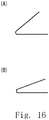
- Fig. 16A There are two ways for folding the sheet along the crease. As shown in Fig. 16A , one way is pressing a recess side of the crease by the folding knife and folding the sheet along the crease in the same direction as the fold direction of the crease. As shown in Fig. 16B , the other way is pressing a protrusion side of the crease by the folding knife and folding the sheet along the crease in a direction opposite to the fold direction of the crease.
- the sheet is a heavy paper sheet, as shown in Fig. 16A , if the sheet is folded in the same direction as the fold direction of the crease, the appearance of the folded sheet is poor because the sheet is not folded completely. Therefore, preferably as shown in Fig. 16B , the sheet is folded in the opposite direction to the fold direction of the crease so as to fold the sheet completely.
- the sheet is a thin paper sheet
- the sheet is folded in the opposite direction to the fold direction of the crease, the appearance of the folded sheet is poor because the folded port ion of the sheet is not sharp. Therefore, the sheet is preferably folded in the same direction as the fold direction of the crease in such a way that the folded portion of the sheet is sharp.
- the creasing section comprises: a convex block opposite to a first surface of the sheet; and a concave block opposite to a second surface of the sheet.
- the convex and concave blocks move toward each other so as to form the crease which provides a recess on the first surface of the sheet and a protrusion on the second surface of the sheet.
- the creasing section has only one set of the convex and concave blocks.
- the creasing section can form only one type of the crease which provides a recess on the first surface of the sheet and a protrusion on the second surface of the sheet.
- the folding mechanism is configured to press the second surface of the sheet by first folding knife and further press the first surface of the sheet by second folding knife so as to fold the sheet two times.
- the sheet is folded by the first folding knife in a direction opposite to the fold direction of the crease (see Fig. 16B ), and further the sheet is folded by the second folding knife in the same direction as the fold direction of the crease (see Fig. 16A ).
- the appearance of the folded sheet is poor because the foldedportion of the sheet is not folded completely (see Fig. 16A ) due to folding the sheet by the second folding knife in the same direction as the fold direction of the crease.
- the appearance of the folded sheet is poor because the folded portion of the sheet is not sharp due to folding the sheet by the first folding knife in a direction opposite to the fold direction of the crease.
- the present invention provides a creasing and folding machine, comprising:
- the controller controls the creasing and the folding mechanisms in such a way that the folding knives press a protrusion side of the first or second crease.
- the controller controls the creasing and the folding mechanisms in such a way that the folding knives press a recess side of the first or second crease.
- the folding mechanism comprises:
- the folding mechanism comprises:
- the creasing section comprises first and second creasing units which are aligned in a conveying direction of the sheet.
- the first creasing unit comprises: a first convex block opposite to the first surface of the sheet; and a first concave block opposite to the second surface of the sheet.
- the first convex and concave blocks move toward each other so as to form a first crease which provides a recess on the first surface of the sheet and a protrusion on the second surface of the sheet.
- the second creasing unit comprises : a second concave block opposite to the first surface of the sheet; and a second convex block opposite to the second surface of the sheet.
- the second concave and convex blocks move toward each other so as to form a second crease which provides a recess on the second surface of the sheet and a protrusion on the first surface of the sheet.
- a folding knife is configured to press the second surface of the sheet, when the first creasing unit forms the crease and provides the protrusion on the second surface of the sheet, the folding knife can press the protrusion side of the crease. Therefore, it is possible to fold a heavy paper sheet with good appearance.
- the folding knife can also press the recess side of the crease. Therefore, it is also possible to fold a thin paper sheet with good appearance.
- the first and second folding units comprise two pairs of the concave and convex blocks which are disposed in different direction from each other. It is possible to form two types of the creases whose protrusion and recess sides are inverted each other.
- the sheet can be folded in two ways: in one way the folding knife presses the protrusion side of the crease, in the other way the folding knife presses the recess side of the crease. In the same way, the sheet can be folded in the direction same as or opposite to the fold direction of the crease. Consequently, it is possible to fold the sheet with good appearance for both heavy and thin paper sheets.
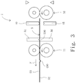
- the creasing and folding machine comprises a creasing mechanism 1 for forming a plurality of creases on a sheet S.
- the creasing and folding machine further comprises a folding mechanism 2 for folding the sheet S along the creases.
- the sheet S is conveyed from the creasing mechanism 1.
- the creasing and folding machine further comprises a controller 3 for controlling operations of the creasing mechanism 1 and the folding mechanism 2.
- the creasing mechanism 1 further comprises first and second conveying roller pairs 10, 11 for conveying the sheet S.
- the first and second conveying roller pairs 10, 11 are aligned in a first conveying direction F of the sheet S.
- the first conveying roller pair 10 is disposed at the upstream of the first conveying direction F, while the second conveying roller pair 11 is disposed at the downstream of the first conveying direction F.
- the first conveying roller pair 10 comprises a first drive roller 100 and a first idle roller 101.
- the first drive and idle rollers 100, 101 are disposed adjacent to each other in such a way that the rotation of the first drive roller 100 causes the rotation of the first idle roller 101.
- the second conveying roller pair 11 comprises a second drive roller 110 and a second idle roller 111.
- the second drive and idle rollers 110, 111 are disposed adjacent to each other in such a way that the rotation of the second drive roller 110 causes the rotation of the second idle roller 111.
- the first and second idle rollers 101, 111 are disposed opposite to the first surface (upper surface) S1 of the sheet S, while the first and second drive rollers 100, 110 support the second surface (lower surface) S2 of the sheet S thereon.
- the creasing mechanism 1 comprises a creasing section 45 for creasing the sheet S.
- the creasing section 45 is disposed between the first and second conveying roller pairs 10, 11.
- the creasing section 45 comprises first and second creasing units 4, 5.
- the first and second creasing units 4, 5 are aligned in a first conveying direction F of the sheet S.
- the first creasing unit 4 is disposed at the upstream of the first conveying direction F, while the second creasing unit 5 is disposed at the downstream of the first conveying direction F.
- the first creasing unit 4 comprises first convex and concave blocks 40, 41.
- the first convex block 40 is disposed opposite to the first surface (upper surface) S1 of the sheet S, while the first concave block 41 is disposed opposite to the second surface (lower surface) S2 of the sheet S.
- the first convex and concave blocks 40, 41 extend horizontally and perpendicular to the first conveying direction F respectively.
- the first convex and concave blocks 40, 41 can be engaged with each other.
- the first convex block 40 is fixed, while the first concave block 41 is reciprocated by a first creasing drive mechanism 42. During reciprocal movement, the first concave block 41 moves toward and away from the first convex block 40.
- the sheet S is nipped between the first convex and concave blocks 40, 41 so as to form a first crease 400.
- the first crease 400 is depressed in the first surface S1 of the sheet S and projected on the second surface S2 of the sheet S.
- the first crease 400 provides a recess on the first surface S1 of the sheet S and a protrusion on the second surface S2 of the sheet S.
- the second creasing unit 5 comprises second convex and concave blocks 50, 51.
- the second convex block 50 is disposed opposite to the second surface (lower surface) S2 of the sheet S, while the second concave block 51 is disposed opposite to the first surface (upper surface) S1 of the sheet S.
- the second convex and concave blocks 50, 51 extend horizontally and perpendicular to the first conveying direction F respectively.
- the second convex and concave blocks 50, 51 can be engaged with each other.
- the second concave block 51 is fixed, while the second convex block 50 is reciprocated by a second creasing drive mechanism 52. During the reciprocal movement, the second convex block 50 moves toward and away from the second concave block 51.
- the sheet S is nipped between the second convex and concave blocks 50, 51 so as to form a second crease 500.
- the second crease 500 is projected on the first surface S1 of the sheet S and depressed in the second surface S2 of the sheet S.
- the second crease 500 provides a protrusion on the first surface S1 of the sheet S and a recess on the second surface S2 of the sheet S.
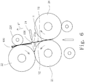
- the folding mechanism 2 comprises first, second and thirdfoldingrollers20, 21, 22.
- the foldingmechanism2 comprises first and second folding knives 23, 24.
- the first and second folding rollers 20, 21 are aligned in the first conveying direction F.
- the first and second folding rollers 20, 21 are disposed adjacent to each other with a small first gap 201 therebetween.
- An edge 23a of the first folding knife 23 is opposite to the first gap 201.
- the second and third rollers 21, 22 are aligned in a second conveying direction F'.
- the second conveying direction F' is arranged at approximately right angle to the first conveying direction F.
- the second and third folding rollers 21, 22 are disposed adjacent to each other with a small second gap 202 therebetween.
- An edge 24a of the second folding knife 24 is opposite to the second gap 202.
- the first folding knife 23 is reciprocated by a first knife drive mechanism 230. During the reciprocal movement, the first folding knife 23 moves toward and away from the first gap 201 in a direction perpendicular to the first conveying direction F. The first folding knife 23 presses the creases 400, 500 of the sheet S from the second surface S2 of the sheet S to the first surface S1 of the sheet S.
- the second folding knife 24 is reciprocated by a second knife drive mechanism 240. During the reciprocal movement, the second folding knife 24 moves toward and away from the second gap 202 in a direction perpendicular to the second conveying direction F'. The second folding knife 24 presses the creases 400, 500 of the sheet S from the first surface S1 of the sheet S to the second surface S2 of the sheet S.
- the folding mechanism 2 comprises first, second and third press rollers 200, 210, 220.
- a first folding unit 6 is composed of the first and second folding rollers 20, 21 and the first folding knife 23.
- a second folding unit 7 is composed of the second and third folding rollers 21, 22 and the second folding knife 24.
- the creasing mechanism 1 forms the creases 400, 500 on the sheet S, and the first folding unit 6 folds the sheet S along the creases 400, 500, and then the second folding unit 7 folds the sheet S along the creases 400, 500.
- the creasing and folding machine comprises a motor 12 composed of a servomotor, a stepping motor and so on.
- the motor 12 is connected to the first and second drive rollers 100, 110 and the second folding roller 21 through a first timing belt 121.
- the drive of the motor 12 causes the rotations of the first and second drive rollers 100, 110 and the second folding roller 21.
- the first and third folding rollers 20, 22 are connected to each other through a second timing belt 122.
- the rotation of the second folding roller 21 causes the rotations of the first and third folding rollers 20, 22.
- the rotation of the motor 12 in a counterclockwise direction causes the counterclockwise rotations of the first and second drive rollers 100, 110 and the second folding roller 21.
- the rotation of the second folding roller 21 in a counterclockwise direction causes the clockwise rotations of the first and third folding rollers 20, 22.
- the creasing and folding machine comprises position sensors 13, 13 which are disposed at the entrance of the creasing mechanism 1.
- the position sensors 13, 13 are composed of light emitting and receiving elements for detecting an edge Sa of the sheet S.
- the position sensors 13, the motor 12, the first and second creasing drive mechanisms 42, 52, and the first and second folding knife drive mechanisms 230, 240 are connected to the controller 3.
- the controller 3 controls the operations of the creasing and folding mechanisms 1, 2 based on a preinstalled program when the position sensors 13 detect the edge Sa of the sheet S.
- the first and second creasing drive mechanisms 42, 52 comprise, for example, a motor and a cam respectively.
- the drives of the cams of the first and second creasing drive mechanisms 42, 52 cause the reciprocal movements of the first concave block 41 and the second convex block 50.
- the first and second creasing drive mechanisms 42, 52 may be composed of a slide crank mechanism, a cylinder mechanism or a feed screw mechanism driven by a motor respectively.
- the controller 3 is provided with a program for handling the heavy paper sheet S. After distances from the edge Sa of the sheet S to the first and second creases 400, 500 are inputted to the controller 3, the operations of the creasing mechanism 1 and the folding mechanism 2 are controlled by the controller 3 as follows.
- the sheet S is conveyed in the first conveying direction F in such a way that a position to be provided with the first crease 400 arrives at the first convex and concave blocks 40, 41 by controlling the amount of the rotations of the conveying rollers 10, 11.
- the position to be provided with the first crease 400 arrives at the first convex and concave blocks 40, 41
- the sheet S is stopped by the stops of the conveying rollers 10, 11.
- the first concave block 41 moves upwardly toward the first convex block 40.
- the first crease 400 is formed on the sheet S.
- the first crease 400 provides a recess on the first surface (upper surface) S1 of the sheet S and a protrusion on the second surface (lower surface) S2 of the sheet S.
- the sheet S is conveyed in the first conveying direction F in such a way that a position to be provided with the second crease 500 arrives at the second convex and concave blocks 50, 51 by controlling the amount of the rotation of the conveying rollers 10, 11.
- the sheet S is stopped by the stops of the conveying rollers 10, 11.
- the second convex block 50 moves toward the second concave block 51.
- the second crease 500 is formed on the sheet S.
- the second crease 500 provides a protrusion on the first surface (upper surface) S1 of the sheet S and a recess on the second surface (lower surface) S2 of the sheet S.
- the sheet S is conveyed in the first conveying direction F in such a way that the first crease 400 arrives at the edge 23a of the first folding knife 23 by controlling the amount of the rotations of the conveying roller 11 and the first folding roller 20.
- the sheet S is discharged from the second conveying roller 11, and then the discharged sheet S is nipped and conveyed between the first folding and press rollers 20, 200.
- the second press roller 210 is separated from the second folding roller 21 in order not to convey the sheet S in a direction opposite to the first conveying direction F by an inverse rotation of the second folding roller 21.
- the second press roller 210 moves upwardly toward the second folding roller 21, and then the first folding knife 23 moves.
- the first folding roller 20 rotates in a clockwise direction, while the second folding roller 21 rotates in a counterclockwise direction.
- the edge 23a of the first folding knife 23 presses the first crease 400.
- the first crease 400 is inserted into the first gap 201 between the first and second folding rollers 20, 21.
- the edge 23a of the first folding knife 23 presses the protrusion side of the first crease 400.
- the sheet S is inserted into the first gap 201 and folded along the first crease 400 and discharged from the first and second folding rollers 20, 21.
- the sheet S is folded in a direction opposite to the fold direction of the first crease 400.
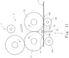
- the sheet S is conveyed in the second conveying direction F' in such a way that the second crease 500 arrives at the edge 24a of the second folding knife 24 by controlling the amount of the rotations of the first and second folding rollers 20, 21.
- the second conveying direction F' is arranged at approximately right angle to the first conveying direction F.
- the third press roller 220 is separated from the third folding roller 22 in order not to convey the sheet S in a direction opposite to the second conveying direction F' by an inverse rotation of the third folding roller 22.
- the third press roller 220 moves laterally toward the third folding roller 22, and then the second folding knife 24 moves.
- the first folding roller 20 rotates in a clockwise direction
- the second folding roller 21 rotates in a counterclockwise direction
- the third folding roller 22 rotates in a clockwise direction.
- the edge 24a of the second folding knife 24 presses the second crease 500.
- the second crease 500 is inserted into the second gap 202 between the second and third folding rollers 21, 22.
- the edge 24a of the second folding knife 24 presses the protrusion side of the second crease 500.
- the sheet S is inserted into the second gap 202 and folded along the second crease 500 and discharged from the second and third folding rollers 21, 22.
- the sheet S is folded in a direction opposite to the fold direction of the second crease 500.
- the sheet S is folded along the first and second creases 400, 500.
- the machine of the present invention can fold the heavy paper sheet S in a direction opposite to the fold directions of the first and second creases 400, 500 (see Fig. 16B ). As a result, the sheet S can be folded with good appearance because the sheet S can be folded completely.
- the sheet is a thin paper sheet
- the controller 3 is provided with a program for handling the thin paper sheet S. After distances from the edge Sa of the sheet S to the first and second creases 400, 500 are inputted to the controller 3, the operations of the creasing mechanism 1 and the folding mechanism 2 are controlled by the controller 3 as follows.
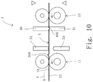
- the sheet S is conveyed in the first conveying direction F in such a way that a position to be provided with the second crease 500 arrives at the second convex and concave blocks 50, 51 by controlling the amount of the rotations of the conveying rollers 10, 11.
- the sheet S is stopped by stopping the conveying rollers 10, 11.
- the second convex block 50 moves upwardly toward the second concave block 51.
- the second crease 500 is formed on the sheet S.
- the second crease 500 provides a protrusion on the first surface (upper surface) S1 of the sheet S and a recess on the second surface (lower surface) S2 of the sheet S.
- the sheet S is conveyed in the first conveying direction F in such a way that a position to be provided with the first crease 400 arrives at the first convex and concave blocks 40, 41 by controlling the amount of the rotations of the conveying rollers 10, 11.
- the sheet S is stopped by stopping the conveying rollers 10, 11.
- the first concave block 41 moves upwardly toward the first convex block 40.
- the first crease 500 is formed on the sheet S.
- the first crease 400 provides a recess on the first surface (upper surface) S1 of the sheet S and a protrusion on the second surface (lower surface) S2 of the sheet S.
- the sheet S is conveyed in the first conveying direction F in such a way that the second crease 500 arrives at the edge 23a of the first folding knife 23 by controlling the amount of the rotations of the conveying roller 11 and the first folding roller 20.
- the sheet S is discharged from the second conveying roller 11, then the discharged sheet S is nipped and conveyed between the first folding and press rollers 20, 200.
- the second press roller 210 is separated from the second folding roller 21 in order not to convey the sheet S in a direction opposite to the first conveying direction F by an inverse rotation of the second folding roller 21.
- the second press roller 210 moves upwardly toward the second folding roller 21, and then the first folding knife 23 moves.
- the first folding roller 20 rotates in a clockwise direction, while the second folding roller 21 rotates in a counterclockwise direction.
- the edge 23a of the first folding knife 23 presses the second crease 500.
- the second crease 500 is inserted into the first gap 201 between the first and second folding rollers 20, 21.
- the edge 23a of the first folding knife 23 presses the recess side of the second crease 500.
- the sheet S is inserted into the first gap 201 and folded along the second crease 500 and discharged from the first and second folding rollers 20, 21.
- the sheet S is folded in the same direction as the fold direction of the second crease 500.
- the sheet S is conveyed in the second conveying direction F' in such a way that the first crease 400 arrives at the edge 24a of the second folding knife 24 by controlling the amount of the rotations of the first and second folding rollers 20, 21.
- the second conveying direction F' is arranged at approximately right angle to the first conveying direction F.
- the third press roller 220 is separated from the third folding roller 22 in order not to convey the sheet S in a direction opposite to the second conveying direction F' by an inverse rotation of the third folding roller 22.
- the third press roller 220 moves laterally toward the third folding roller 22, and then the second folding knife 24 moves.
- the first folding roller 20 rotates in a clockwise direction
- the second folding roller 21 rotates in a counterclockwise direction
- the third folding roller 22 rotates in a clockwise direction.
- the edge 24a of the second folding knife 24 presses the first crease 400.
- the first crease 400 is inserted into the second gap 202 between the second and third folding rollers 21, 22.
- the edge 24a of the second folding knife 24 presses the recess side of the first crease 400.
- the sheet S is inserted into the second gap 202 and folded along the first crease 400 and discharged from the second and third folding rollers 21, 22.
- the sheet S is folded in the same direction as the fold direction of the first crease 400.
- the sheet S is folded along the first and second creases 400, 500.
- the machine of the present invention can fold the thin paper sheet S in the same direction as the folddirections of the first and second creases 400, 500 (see Fig. 16A ).
- the sheet S can be folded with good appearance because the folded portion of the sheet S can be sharp.
Landscapes
- Engineering & Computer Science (AREA)
- Mechanical Engineering (AREA)
- Folding Of Thin Sheet-Like Materials, Special Discharging Devices, And Others (AREA)
- Machines For Manufacturing Corrugated Board In Mechanical Paper-Making Processes (AREA)
Claims (5)
- Machine de rainage-pliage, comprenant :un mécanisme de rainage (1) destiné à former une pluralité de rainures sur une feuille (S) ;un mécanisme de pliage (2) destiné à recevoir la feuille (S) provenant du mécanisme de rainage (1) et à plier la feuille (S) le long des rainures ; etune unité de commande (3) destinée à commander les opérations du mécanisme de rainage (1) et du mécanisme de pliage (2) ; dans laquellele mécanisme de rainage (1) comprend :un rouleau d'acheminement (10,11) destiné à acheminer la feuille (S) ; etune section de rainage (45) destinée à rainurer la feuille (S) qui est délivrée par le rouleau d'acheminement (10,11) ; dans laquellele mécanisme de pliage (2) comprend :une pluralité de lames de pliage destinées à presser la feuille (S) le long des rainures au niveau de bords des lames de pliage ; etune pluralité de paires de rouleaux de pliage, chacune étant composée de deux rouleaux de pliage disposés l'un en face de l'autre avec un espace entre eux, les espaces étant opposés aux bords des lames de pliage ; dans laquellela feuille (S) est pressée par les lames de pliage de manière à être insérée dans les espaces et pliée le long des rainures ;caractérisée en ce quela section de rainage (45) comprend :des première et seconde unités de rainage (4,5) alignées dans un sens d'acheminement (F, F') de la feuille (S) ; dans laquellela première unité de rainage (4) comprend :un premier bloc convexe (40) opposé à une première surface de la feuille (S1) ; etun premier bloc concave (41) opposé à une seconde surface de la feuille (S2), les premiers blocs convexe et concave étant déplacés l'un vers l'autre de manière à former une première rainure (400) des rainures qui produit un renfoncement sur la première surface de la feuille (S1) et une protubérance sur la seconde surface de la feuille (S2) ; et dans laquellela seconde unité de rainage (5) comprend :un second bloc concave (51) opposé à la première surface de la feuille (S1) ; etun second bloc convexe (50) opposé à la seconde surface de la feuille (S2), les seconds blocs concave et convexe étant déplacés l'un vers l'autre de manière à former une seconde rainure (500) des rainures qui produit une protubérance sur la première surface de la feuille (S1) et un renfoncement sur la seconde surface de la feuille (S2).
- Machine de rainage-pliage selon la revendication 1, dans laquelle
quand la feuille (S) est une feuille de papier épaisse, l'unité de commande (3) commande les mécanismes de rainage et de pliage (1,2) de telle sorte que les lames de pliage pressent un côté à protubérance de la première ou seconde rainure. - Machine de rainage-pliage selon la revendication 1, dans laquelle
quand la feuille (S) est une feuille de papier mince, l'unité de commande (3) commande les mécanismes de rainage et de pliage (1,2) de telle sorte que les lames de pliage pressent un côté à renfoncement de la première ou seconde rainure. - Machine de rainage-pliage selon la revendication 1, dans laquelle
le mécanisme de pliage (2) comprend :les paires des rouleaux de pliage comportant deux paires de rouleaux de pliage, une première paire de rouleaux de pliage (20,21) des deux paires de rouleaux de pliage étant composée d'un premier rouleau de pliage (20) et d'un deuxième rouleau de pliage (21), et une seconde paire de rouleaux de pliage (21,22) des deux paires de rouleaux de pliage étant composée du deuxième rouleau de pliage (21) et d'un troisième rouleau de pliage (22) ; etles lames de pliage comportant des première et seconde lames de pliage ; dans laquelleune première unité de pliage (6) est composée de la première paire de rouleaux de pliage (20,21) et de la première lame de pliage (23), dans laquelle
une seconde unité de pliage (7) est composée de la seconde paire de rouleaux de pliage (21,22) et de la seconde lame de pliage (24), dans laquelle
la première unité de pliage (6) plie la feuille (S) de telle façon que la première lame de pliage (23) presse la première ou seconde rainure de la seconde surface de la feuille (S2) contre la première surface de la feuille (S1) et insère la feuille (S) dans l'espace entre les premier et deuxième rouleaux de pliage, dans laquelle
la seconde unité de pliage (7) plie la feuille (S) de telle façon que la seconde lame de pliage (24) presse la première ou seconde rainure de la première surface de la feuille (S1) contre la seconde surface de la feuille (S2) et insère la feuille (S) dans l'espace entre les deuxième et troisième rouleaux de pliage, et dans laquelle
quand la feuille (S) est une feuille de papier épaisse, l'unité de commande (3) commande les mécanismes de rainage et de pliage (1,2) de telle façon que la seconde unité de rainage (5) forme la seconde rainure (500) après que la première unité de rainage (4) a formé la première rainure (400), et la première lame de pliage (23) presse le côté à protubérance de la première rainure (400), puis la seconde lame de pliage (24) presse le côté à protubérance de la seconde rainure (500). - Machine de rainage-pliage selon la revendication 1, dans laquelle
le mécanisme de pliage (2) comprend :les paires de rouleaux de pliage comportant deux paires de rouleaux de pliage, une première paire de rouleaux de pliage (20,21) des deux paires de rouleaux de pliage étant composée d'un premier rouleau de pliage (20) et d'un deuxième rouleau de pliage (21), et une seconde paire de rouleaux de pliage (21,22) des deux paires de rouleaux de pliage étant composée du deuxième rouleau de pliage (21) et d'un troisième rouleau de pliage (22) ; etles lames de pliage comportant des première et seconde lames de pliage ; dans laquelleune première unité de pliage (6) est composée de la première paire de rouleaux de pliage (20, 21) et de la première lame de pliage (23), dans laquelle
une seconde unité de pliage (7) est composée de la seconde paire de rouleaux de pliage (21,22) et de la seconde lame de pliage (24), dans laquelle
la première unité de pliage (6) plie la feuille (S) de telle façon que la première lame de pliage (23) presse la première ou seconde rainure de la seconde surface de la feuille (S2) contre la première surface de la feuille (S1) et insère la feuille (S) dans l'espace entre les premier et deuxième rouleaux de pliage, dans laquelle
la seconde unité de pliage (7) plie la feuille (S) de telle façon que la seconde lame de pliage (24) presse la première ou seconde rainure de la première surface de la feuille (S1) contre la seconde surface de la feuille (S2) et insère la feuille (S) dans l'espace entre les deuxième et troisième rouleaux de pliage, et dans laquelle
quand la feuille (S) est une feuille de papier mince, l'unité de commande (3) commande les mécanismes de rainage et de pliage (1,2) de telle façon que la première unité de rainage (4) forme la première rainure (400) après que la seconde unité de rainage (5) a formé la seconde rainure (500), et la première lame de pliage (23) presse le côté à renfoncement de la seconde rainure (500), puis la seconde lame de pliage (24) presse le côté à renfoncement de la première rainure (400).
Applications Claiming Priority (1)
| Application Number | Priority Date | Filing Date | Title |
|---|---|---|---|
| PCT/JP2012/061537 WO2013164877A1 (fr) | 2012-05-01 | 2012-05-01 | Dispositif de formation de ligne de pli et de pliage |
Publications (3)
| Publication Number | Publication Date |
|---|---|
| EP2845829A1 EP2845829A1 (fr) | 2015-03-11 |
| EP2845829A4 EP2845829A4 (fr) | 2016-04-20 |
| EP2845829B1 true EP2845829B1 (fr) | 2017-06-28 |
Family
ID=49514287
Family Applications (1)
| Application Number | Title | Priority Date | Filing Date |
|---|---|---|---|
| EP12875778.8A Not-in-force EP2845829B1 (fr) | 2012-05-01 | 2012-05-01 | Dispositif de rainurage et de pliage |
Country Status (6)
| Country | Link |
|---|---|
| US (1) | US20140357463A1 (fr) |
| EP (1) | EP2845829B1 (fr) |
| JP (1) | JP5872029B2 (fr) |
| CN (1) | CN103889871B (fr) |
| DK (1) | DK2845829T3 (fr) |
| WO (1) | WO2013164877A1 (fr) |
Families Citing this family (31)
| Publication number | Priority date | Publication date | Assignee | Title |
|---|---|---|---|---|
| JP6077556B2 (ja) | 2011-11-10 | 2017-02-08 | パックサイズ,エルエルシー | 変換機械 |
| JP6329389B2 (ja) | 2014-02-25 | 2018-05-23 | キヤノン株式会社 | 画像形成システム、及び画像形成装置 |
| DE102014206083A1 (de) * | 2014-03-31 | 2015-10-01 | Foldcore Gmbh | Verfahren zur Umformung eines Flachbahnmaterials und Vorrichtung |
| JP2016030671A (ja) * | 2014-07-29 | 2016-03-07 | キヤノン株式会社 | シート処理装置及びその制御方法、並びにプログラム |
| JP6412756B2 (ja) * | 2014-09-26 | 2018-10-24 | 富士ゼロックス株式会社 | 用紙および用紙搬送方法 |
| JP6378021B2 (ja) * | 2014-09-26 | 2018-08-22 | 富士ゼロックス株式会社 | 用紙 |
| US9914614B2 (en) * | 2014-09-26 | 2018-03-13 | Fuji Xerox Co., Ltd. | Sheet, sheet conveying apparatus and sheet conveying method |
| US10093438B2 (en) | 2014-12-29 | 2018-10-09 | Packsize Llc | Converting machine |
| ITUB20161084A1 (it) * | 2016-02-26 | 2017-08-26 | K G S S R L Unipersonale | Dispositivo di cordonatura per la realizzazione di cordoni di piegatura in articoli cartotecnici e di legatoria, nonche' macchina comprendente tale dispositivo |
| RU2737267C2 (ru) | 2016-06-16 | 2020-11-26 | Пэксайз Ллс | Система для производства заготовок для коробок и соответствующий способ |
| US10850469B2 (en) | 2016-06-16 | 2020-12-01 | Packsize Llc | Box forming machine |
| JP6848331B2 (ja) * | 2016-10-24 | 2021-03-24 | 富士ゼロックス株式会社 | 後処理装置及び画像形成システム |
| US11242214B2 (en) * | 2017-01-18 | 2022-02-08 | Packsize Llc | Converting machine with fold sensing mechanism |
| SE541921C2 (en) | 2017-03-06 | 2020-01-07 | Packsize Llc | A box erecting method and system |
| SE540672C2 (en) | 2017-06-08 | 2018-10-09 | Packsize Llc | Tool head positioning mechanism for a converting machine, and method for positioning a plurality of tool heads in a converting machine |
| EP3648908B1 (fr) | 2017-07-06 | 2025-08-20 | Bobst Mex Sa | Procédé de plissage de feuilles |
| EP3648964B1 (fr) | 2017-07-06 | 2024-10-23 | Bobst Mex Sa | Machine de rainage et procédé de rainage de feuilles |
| US11173685B2 (en) | 2017-12-18 | 2021-11-16 | Packsize Llc | Method for erecting boxes |
| US11247427B2 (en) | 2018-04-05 | 2022-02-15 | Avercon BVBA | Packaging machine infeed, separation, and creasing mechanisms |
| US11305903B2 (en) | 2018-04-05 | 2022-04-19 | Avercon BVBA | Box template folding process and mechanisms |
| DE112019003075T5 (de) | 2018-06-21 | 2021-03-25 | Packsize Llc | Verpackungsvorrichtung und systeme |
| SE543046C2 (en) | 2018-09-05 | 2020-09-29 | Packsize Llc | A box erecting method and system |
| US11524474B2 (en) | 2018-11-30 | 2022-12-13 | Packsize Llc | Adjustable cutting and creasing heads for creating angled cuts and creases |
| WO2020146334A1 (fr) | 2019-01-07 | 2020-07-16 | Packsize Llc | Machine permettant d'ériger une boîte |
| US11701854B2 (en) | 2019-03-14 | 2023-07-18 | Packsize Llc | Packaging machine and systems |
| CN110239801B (zh) * | 2019-07-17 | 2020-11-06 | 袁文强 | 一种棉花片状物的自动折叠包装机及自动折叠包装方法 |
| CN112323449B (zh) * | 2020-10-30 | 2023-08-01 | 浙江衣拿智能科技股份有限公司 | 一种裁剪机、裁剪系统和智能裁剪方法 |
| DE102020132876A1 (de) | 2020-12-09 | 2022-06-09 | Gerhard Markus Saitner | Doppelfalteinheit zum kreuzweise Falten von flächigen Materialien |
| CN117735321A (zh) * | 2022-09-15 | 2024-03-22 | 大庆油田有限责任公司 | 一种图纸折痕装置 |
| WO2025165397A1 (fr) | 2024-01-29 | 2025-08-07 | Kohlam, Llc | Dispositif d'alignement de composite multicouche |
| CN117842762A (zh) * | 2024-01-30 | 2024-04-09 | 成都赛欧方达智能设备有限公司 | 一种压痕式纸张折叠装置 |
Family Cites Families (11)
| Publication number | Priority date | Publication date | Assignee | Title |
|---|---|---|---|---|
| DE3603647C1 (en) * | 1986-02-06 | 1987-08-20 | Lemke Wolfgang | Folding unit for folding a sheet provided with a strip of glue |
| CN1240402A (zh) * | 1996-10-18 | 2000-01-05 | 曼·胡默尔滤清器有限公司 | 弯折料段的装置 |
| GB0107883D0 (en) * | 2001-03-29 | 2001-05-23 | Morgana Systems Ltd | Folding machine |
| DE10118133B4 (de) * | 2001-04-11 | 2008-10-02 | Weinmann, Karlheinz, Dr. | Verfahren zum Prägen und Falzen von Blattgut und Universalfalzvorrichtung |
| GB0122381D0 (en) * | 2001-09-15 | 2001-11-07 | Morgana Systems Ltd | Creasing and folding process |
| US20030092551A1 (en) * | 2001-11-14 | 2003-05-15 | Roland Boss | Methods and apparatus for scoring and trimming imaged sheet media |
| US6939283B2 (en) * | 2003-08-12 | 2005-09-06 | Xerox Corporation | Booklet maker with flexible gate upstream of crease rolls |
| JP4445899B2 (ja) * | 2004-08-26 | 2010-04-07 | 株式会社リコー | 用紙折り装置及び画像形成装置 |
| JP2009061696A (ja) * | 2007-09-06 | 2009-03-26 | Labonetwork Inc | アルバム製本方法及びアルバム製本装置 |
| JP5445059B2 (ja) * | 2009-11-20 | 2014-03-19 | 株式会社リコー | 折り目付け装置、用紙後処理装置、画像形成装置、画像形成システム |
| CN102741058B (zh) * | 2010-02-02 | 2014-10-29 | 好利用国际株式会社 | 对于向主体粘贴前的封面加入折弯加工用的纹线的装置 |
-
2012
- 2012-05-01 EP EP12875778.8A patent/EP2845829B1/fr not_active Not-in-force
- 2012-05-01 JP JP2014513316A patent/JP5872029B2/ja not_active Expired - Fee Related
- 2012-05-01 US US14/344,262 patent/US20140357463A1/en not_active Abandoned
- 2012-05-01 WO PCT/JP2012/061537 patent/WO2013164877A1/fr not_active Ceased
- 2012-05-01 CN CN201280050506.2A patent/CN103889871B/zh not_active Expired - Fee Related
- 2012-05-01 DK DK12875778.8T patent/DK2845829T3/en active
Non-Patent Citations (1)
| Title |
|---|
| None * |
Also Published As
| Publication number | Publication date |
|---|---|
| CN103889871B (zh) | 2016-09-21 |
| JPWO2013164877A1 (ja) | 2015-12-24 |
| WO2013164877A1 (fr) | 2013-11-07 |
| US20140357463A1 (en) | 2014-12-04 |
| DK2845829T3 (en) | 2017-09-11 |
| EP2845829A4 (fr) | 2016-04-20 |
| EP2845829A1 (fr) | 2015-03-11 |
| JP5872029B2 (ja) | 2016-03-01 |
| CN103889871A (zh) | 2014-06-25 |
Similar Documents
| Publication | Publication Date | Title |
|---|---|---|
| EP2845829B1 (fr) | Dispositif de rainurage et de pliage | |
| JP5664094B2 (ja) | 用紙処理装置及び画像形成システム | |
| DK2860001T3 (en) | Rotation stop | |
| JP5122922B2 (ja) | バックル折りユニットが前に配置されているナイフ折り機と、平坦な被印刷体からなる枚葉紙を折る方法 | |
| US8628457B2 (en) | Method for folding sheets | |
| JP5625870B2 (ja) | 筋付け装置及び画像形成システム | |
| EP2527279B1 (fr) | Dispositif de pliage à couteaux | |
| US8413974B2 (en) | Creasing device and image forming system | |
| US8465012B2 (en) | Creasing device and image forming system | |
| JP2016026975A (ja) | 折り目入れ折り装置 | |
| JP6589805B2 (ja) | シート後処理装置及びそれを備えた画像形成システム | |
| JP2003341929A (ja) | ウェブ輪転印刷機の折り装置 | |
| US8419603B2 (en) | Method for folding sheets | |
| CA3188933A1 (fr) | Plieuse comprenant un groupe de pliage a lame et procede de pliage de produits a plier au moyen d'un groupe de pliage a lame | |
| KR20170032199A (ko) | 시트 처리 장치 및 화상 형성 장치 | |
| CN100522778C (zh) | 具有用于对产品继续加工的交替的加工段的系统、纵向折页机和用于折页机同步工作的方法 | |
| JP6116887B2 (ja) | 用紙処理装置 | |
| EP3450368B1 (fr) | Appareil de post-traitement | |
| US20150057140A1 (en) | Folding machine as combined knife and buckle folders | |
| JP4143291B2 (ja) | シート穿孔装置及び該装置を備えた画像形成装置 | |
| US20180265324A1 (en) | Signature forming method and sheet folding machine | |
| JP2005231861A (ja) | 紙折り装置 | |
| JP5577914B2 (ja) | 筋付け装置、及び画像形成システム | |
| SU1736738A1 (ru) | Фальцевально-швейна поточна лини | |
| KR100838761B1 (ko) | 인쇄기기용 용지 폴딩 장치 |
Legal Events
| Date | Code | Title | Description |
|---|---|---|---|
| PUAI | Public reference made under article 153(3) epc to a published international application that has entered the european phase |
Free format text: ORIGINAL CODE: 0009012 |
|
| 17P | Request for examination filed |
Effective date: 20140520 |
|
| AK | Designated contracting states |
Kind code of ref document: A1 Designated state(s): AL AT BE BG CH CY CZ DE DK EE ES FI FR GB GR HR HU IE IS IT LI LT LU LV MC MK MT NL NO PL PT RO RS SE SI SK SM TR |
|
| AX | Request for extension of the european patent |
Extension state: BA ME |
|
| DAX | Request for extension of the european patent (deleted) | ||
| RA4 | Supplementary search report drawn up and despatched (corrected) |
Effective date: 20160318 |
|
| RIC1 | Information provided on ipc code assigned before grant |
Ipc: B65H 45/18 20060101ALI20160314BHEP Ipc: B65H 45/30 20060101AFI20160314BHEP |
|
| GRAP | Despatch of communication of intention to grant a patent |
Free format text: ORIGINAL CODE: EPIDOSNIGR1 |
|
| STAA | Information on the status of an ep patent application or granted ep patent |
Free format text: STATUS: GRANT OF PATENT IS INTENDED |
|
| RIC1 | Information provided on ipc code assigned before grant |
Ipc: B65H 45/18 20060101ALI20161108BHEP Ipc: B42D 15/00 20060101ALI20161108BHEP Ipc: B65H 45/30 20060101AFI20161108BHEP Ipc: B31F 1/00 20060101ALI20161108BHEP Ipc: B31F 1/08 20060101ALI20161108BHEP |
|
| INTG | Intention to grant announced |
Effective date: 20161130 |
|
| GRAS | Grant fee paid |
Free format text: ORIGINAL CODE: EPIDOSNIGR3 |
|
| GRAJ | Information related to disapproval of communication of intention to grant by the applicant or resumption of examination proceedings by the epo deleted |
Free format text: ORIGINAL CODE: EPIDOSDIGR1 |
|
| GRAL | Information related to payment of fee for publishing/printing deleted |
Free format text: ORIGINAL CODE: EPIDOSDIGR3 |
|
| STAA | Information on the status of an ep patent application or granted ep patent |
Free format text: STATUS: REQUEST FOR EXAMINATION WAS MADE |
|
| GRAR | Information related to intention to grant a patent recorded |
Free format text: ORIGINAL CODE: EPIDOSNIGR71 |
|
| STAA | Information on the status of an ep patent application or granted ep patent |
Free format text: STATUS: GRANT OF PATENT IS INTENDED |
|
| INTC | Intention to grant announced (deleted) | ||
| INTG | Intention to grant announced |
Effective date: 20170406 |
|
| GRAA | (expected) grant |
Free format text: ORIGINAL CODE: 0009210 |
|
| STAA | Information on the status of an ep patent application or granted ep patent |
Free format text: STATUS: THE PATENT HAS BEEN GRANTED |
|
| AK | Designated contracting states |
Kind code of ref document: B1 Designated state(s): AL AT BE BG CH CY CZ DE DK EE ES FI FR GB GR HR HU IE IS IT LI LT LU LV MC MK MT NL NO PL PT RO RS SE SI SK SM TR |
|
| REG | Reference to a national code |
Ref country code: GB Ref legal event code: FG4D |
|
| REG | Reference to a national code |
Ref country code: CH Ref legal event code: EP |
|
| REG | Reference to a national code |
Ref country code: AT Ref legal event code: REF Ref document number: 904652 Country of ref document: AT Kind code of ref document: T Effective date: 20170715 |
|
| REG | Reference to a national code |
Ref country code: IE Ref legal event code: FG4D |
|
| REG | Reference to a national code |
Ref country code: CH Ref legal event code: NV Representative=s name: SERVOPATENT GMBH, CH |
|
| REG | Reference to a national code |
Ref country code: DE Ref legal event code: R096 Ref document number: 602012034091 Country of ref document: DE |
|
| REG | Reference to a national code |
Ref country code: DK Ref legal event code: T3 Effective date: 20170906 |
|
| REG | Reference to a national code |
Ref country code: SE Ref legal event code: TRGR |
|
| PG25 | Lapsed in a contracting state [announced via postgrant information from national office to epo] |
Ref country code: HR Free format text: LAPSE BECAUSE OF FAILURE TO SUBMIT A TRANSLATION OF THE DESCRIPTION OR TO PAY THE FEE WITHIN THE PRESCRIBED TIME-LIMIT Effective date: 20170628 Ref country code: NO Free format text: LAPSE BECAUSE OF FAILURE TO SUBMIT A TRANSLATION OF THE DESCRIPTION OR TO PAY THE FEE WITHIN THE PRESCRIBED TIME-LIMIT Effective date: 20170928 Ref country code: LT Free format text: LAPSE BECAUSE OF FAILURE TO SUBMIT A TRANSLATION OF THE DESCRIPTION OR TO PAY THE FEE WITHIN THE PRESCRIBED TIME-LIMIT Effective date: 20170628 Ref country code: FI Free format text: LAPSE BECAUSE OF FAILURE TO SUBMIT A TRANSLATION OF THE DESCRIPTION OR TO PAY THE FEE WITHIN THE PRESCRIBED TIME-LIMIT Effective date: 20170628 Ref country code: GR Free format text: LAPSE BECAUSE OF FAILURE TO SUBMIT A TRANSLATION OF THE DESCRIPTION OR TO PAY THE FEE WITHIN THE PRESCRIBED TIME-LIMIT Effective date: 20170929 |
|
| REG | Reference to a national code |
Ref country code: NL Ref legal event code: MP Effective date: 20170628 |
|
| REG | Reference to a national code |
Ref country code: LT Ref legal event code: MG4D |
|
| REG | Reference to a national code |
Ref country code: AT Ref legal event code: MK05 Ref document number: 904652 Country of ref document: AT Kind code of ref document: T Effective date: 20170628 |
|
| PG25 | Lapsed in a contracting state [announced via postgrant information from national office to epo] |
Ref country code: NL Free format text: LAPSE BECAUSE OF FAILURE TO SUBMIT A TRANSLATION OF THE DESCRIPTION OR TO PAY THE FEE WITHIN THE PRESCRIBED TIME-LIMIT Effective date: 20170628 Ref country code: LV Free format text: LAPSE BECAUSE OF FAILURE TO SUBMIT A TRANSLATION OF THE DESCRIPTION OR TO PAY THE FEE WITHIN THE PRESCRIBED TIME-LIMIT Effective date: 20170628 Ref country code: RS Free format text: LAPSE BECAUSE OF FAILURE TO SUBMIT A TRANSLATION OF THE DESCRIPTION OR TO PAY THE FEE WITHIN THE PRESCRIBED TIME-LIMIT Effective date: 20170628 Ref country code: BG Free format text: LAPSE BECAUSE OF FAILURE TO SUBMIT A TRANSLATION OF THE DESCRIPTION OR TO PAY THE FEE WITHIN THE PRESCRIBED TIME-LIMIT Effective date: 20170928 |
|
| PG25 | Lapsed in a contracting state [announced via postgrant information from national office to epo] |
Ref country code: RO Free format text: LAPSE BECAUSE OF FAILURE TO SUBMIT A TRANSLATION OF THE DESCRIPTION OR TO PAY THE FEE WITHIN THE PRESCRIBED TIME-LIMIT Effective date: 20170628 Ref country code: CZ Free format text: LAPSE BECAUSE OF FAILURE TO SUBMIT A TRANSLATION OF THE DESCRIPTION OR TO PAY THE FEE WITHIN THE PRESCRIBED TIME-LIMIT Effective date: 20170628 Ref country code: SK Free format text: LAPSE BECAUSE OF FAILURE TO SUBMIT A TRANSLATION OF THE DESCRIPTION OR TO PAY THE FEE WITHIN THE PRESCRIBED TIME-LIMIT Effective date: 20170628 Ref country code: AT Free format text: LAPSE BECAUSE OF FAILURE TO SUBMIT A TRANSLATION OF THE DESCRIPTION OR TO PAY THE FEE WITHIN THE PRESCRIBED TIME-LIMIT Effective date: 20170628 Ref country code: EE Free format text: LAPSE BECAUSE OF FAILURE TO SUBMIT A TRANSLATION OF THE DESCRIPTION OR TO PAY THE FEE WITHIN THE PRESCRIBED TIME-LIMIT Effective date: 20170628 |
|
| PG25 | Lapsed in a contracting state [announced via postgrant information from national office to epo] |
Ref country code: ES Free format text: LAPSE BECAUSE OF FAILURE TO SUBMIT A TRANSLATION OF THE DESCRIPTION OR TO PAY THE FEE WITHIN THE PRESCRIBED TIME-LIMIT Effective date: 20170628 Ref country code: PL Free format text: LAPSE BECAUSE OF FAILURE TO SUBMIT A TRANSLATION OF THE DESCRIPTION OR TO PAY THE FEE WITHIN THE PRESCRIBED TIME-LIMIT Effective date: 20170628 Ref country code: SM Free format text: LAPSE BECAUSE OF FAILURE TO SUBMIT A TRANSLATION OF THE DESCRIPTION OR TO PAY THE FEE WITHIN THE PRESCRIBED TIME-LIMIT Effective date: 20170628 Ref country code: IS Free format text: LAPSE BECAUSE OF FAILURE TO SUBMIT A TRANSLATION OF THE DESCRIPTION OR TO PAY THE FEE WITHIN THE PRESCRIBED TIME-LIMIT Effective date: 20171028 |
|
| REG | Reference to a national code |
Ref country code: DE Ref legal event code: R097 Ref document number: 602012034091 Country of ref document: DE |
|
| PLBE | No opposition filed within time limit |
Free format text: ORIGINAL CODE: 0009261 |
|
| REG | Reference to a national code |
Ref country code: FR Ref legal event code: PLFP Year of fee payment: 7 |
|
| 26N | No opposition filed |
Effective date: 20180329 |
|
| PG25 | Lapsed in a contracting state [announced via postgrant information from national office to epo] |
Ref country code: SI Free format text: LAPSE BECAUSE OF FAILURE TO SUBMIT A TRANSLATION OF THE DESCRIPTION OR TO PAY THE FEE WITHIN THE PRESCRIBED TIME-LIMIT Effective date: 20170628 |
|
| REG | Reference to a national code |
Ref country code: DK Ref legal event code: EBP Effective date: 20180531 |
|
| PG25 | Lapsed in a contracting state [announced via postgrant information from national office to epo] |
Ref country code: MC Free format text: LAPSE BECAUSE OF FAILURE TO SUBMIT A TRANSLATION OF THE DESCRIPTION OR TO PAY THE FEE WITHIN THE PRESCRIBED TIME-LIMIT Effective date: 20170628 |
|
| REG | Reference to a national code |
Ref country code: IE Ref legal event code: MM4A |
|
| PG25 | Lapsed in a contracting state [announced via postgrant information from national office to epo] |
Ref country code: LU Free format text: LAPSE BECAUSE OF NON-PAYMENT OF DUE FEES Effective date: 20180501 |
|
| PG25 | Lapsed in a contracting state [announced via postgrant information from national office to epo] |
Ref country code: IE Free format text: LAPSE BECAUSE OF NON-PAYMENT OF DUE FEES Effective date: 20180501 |
|
| PG25 | Lapsed in a contracting state [announced via postgrant information from national office to epo] |
Ref country code: DK Free format text: LAPSE BECAUSE OF NON-PAYMENT OF DUE FEES Effective date: 20180531 |
|
| PG25 | Lapsed in a contracting state [announced via postgrant information from national office to epo] |
Ref country code: MT Free format text: LAPSE BECAUSE OF NON-PAYMENT OF DUE FEES Effective date: 20180501 |
|
| PG25 | Lapsed in a contracting state [announced via postgrant information from national office to epo] |
Ref country code: TR Free format text: LAPSE BECAUSE OF FAILURE TO SUBMIT A TRANSLATION OF THE DESCRIPTION OR TO PAY THE FEE WITHIN THE PRESCRIBED TIME-LIMIT Effective date: 20170628 |
|
| PG25 | Lapsed in a contracting state [announced via postgrant information from national office to epo] |
Ref country code: PT Free format text: LAPSE BECAUSE OF FAILURE TO SUBMIT A TRANSLATION OF THE DESCRIPTION OR TO PAY THE FEE WITHIN THE PRESCRIBED TIME-LIMIT Effective date: 20170628 Ref country code: HU Free format text: LAPSE BECAUSE OF FAILURE TO SUBMIT A TRANSLATION OF THE DESCRIPTION OR TO PAY THE FEE WITHIN THE PRESCRIBED TIME-LIMIT; INVALID AB INITIO Effective date: 20120501 |
|
| REG | Reference to a national code |
Ref country code: CH Ref legal event code: PCAR Free format text: NEW ADDRESS: WANNERSTRASSE 9/1, 8045 ZUERICH (CH) |
|
| PG25 | Lapsed in a contracting state [announced via postgrant information from national office to epo] |
Ref country code: CY Free format text: LAPSE BECAUSE OF FAILURE TO SUBMIT A TRANSLATION OF THE DESCRIPTION OR TO PAY THE FEE WITHIN THE PRESCRIBED TIME-LIMIT Effective date: 20170628 Ref country code: MK Free format text: LAPSE BECAUSE OF NON-PAYMENT OF DUE FEES Effective date: 20170628 |
|
| PG25 | Lapsed in a contracting state [announced via postgrant information from national office to epo] |
Ref country code: AL Free format text: LAPSE BECAUSE OF FAILURE TO SUBMIT A TRANSLATION OF THE DESCRIPTION OR TO PAY THE FEE WITHIN THE PRESCRIBED TIME-LIMIT Effective date: 20170628 |
|
| STAA | Information on the status of an ep patent application or granted ep patent |
Free format text: STATUS: NO OPPOSITION FILED WITHIN TIME LIMIT |
|
| PGFP | Annual fee paid to national office [announced via postgrant information from national office to epo] |
Ref country code: DE Payment date: 20210520 Year of fee payment: 10 Ref country code: IT Payment date: 20210527 Year of fee payment: 10 Ref country code: FR Payment date: 20210525 Year of fee payment: 10 |
|
| PGFP | Annual fee paid to national office [announced via postgrant information from national office to epo] |
Ref country code: SE Payment date: 20210519 Year of fee payment: 10 Ref country code: BE Payment date: 20210519 Year of fee payment: 10 Ref country code: GB Payment date: 20210525 Year of fee payment: 10 Ref country code: CH Payment date: 20210519 Year of fee payment: 10 |
|
| REG | Reference to a national code |
Ref country code: DE Ref legal event code: R119 Ref document number: 602012034091 Country of ref document: DE |
|
| REG | Reference to a national code |
Ref country code: CH Ref legal event code: PL |
|
| REG | Reference to a national code |
Ref country code: SE Ref legal event code: EUG |
|
| REG | Reference to a national code |
Ref country code: BE Ref legal event code: MM Effective date: 20220531 |
|
| GBPC | Gb: european patent ceased through non-payment of renewal fee |
Effective date: 20220501 |
|
| PG25 | Lapsed in a contracting state [announced via postgrant information from national office to epo] |
Ref country code: SE Free format text: LAPSE BECAUSE OF NON-PAYMENT OF DUE FEES Effective date: 20220502 Ref country code: LI Free format text: LAPSE BECAUSE OF NON-PAYMENT OF DUE FEES Effective date: 20220531 Ref country code: CH Free format text: LAPSE BECAUSE OF NON-PAYMENT OF DUE FEES Effective date: 20220531 |
|
| PG25 | Lapsed in a contracting state [announced via postgrant information from national office to epo] |
Ref country code: FR Free format text: LAPSE BECAUSE OF NON-PAYMENT OF DUE FEES Effective date: 20220531 |
|
| PG25 | Lapsed in a contracting state [announced via postgrant information from national office to epo] |
Ref country code: GB Free format text: LAPSE BECAUSE OF NON-PAYMENT OF DUE FEES Effective date: 20220501 Ref country code: DE Free format text: LAPSE BECAUSE OF NON-PAYMENT OF DUE FEES Effective date: 20221201 Ref country code: BE Free format text: LAPSE BECAUSE OF NON-PAYMENT OF DUE FEES Effective date: 20220531 |
|
| PG25 | Lapsed in a contracting state [announced via postgrant information from national office to epo] |
Ref country code: IT Free format text: LAPSE BECAUSE OF NON-PAYMENT OF DUE FEES Effective date: 20220501 |