EP2845954A1 - Hybridarbeitsmaschine - Google Patents
Hybridarbeitsmaschine Download PDFInfo
- Publication number
- EP2845954A1 EP2845954A1 EP13785272.9A EP13785272A EP2845954A1 EP 2845954 A1 EP2845954 A1 EP 2845954A1 EP 13785272 A EP13785272 A EP 13785272A EP 2845954 A1 EP2845954 A1 EP 2845954A1
- Authority
- EP
- European Patent Office
- Prior art keywords
- pressure
- hydraulic pump
- engine
- pump
- hydraulic
- Prior art date
- Legal status (The legal status is an assumption and is not a legal conclusion. Google has not performed a legal analysis and makes no representation as to the accuracy of the status listed.)
- Withdrawn
Links
Images





Classifications
-
- F—MECHANICAL ENGINEERING; LIGHTING; HEATING; WEAPONS; BLASTING
- F15—FLUID-PRESSURE ACTUATORS; HYDRAULICS OR PNEUMATICS IN GENERAL
- F15B—SYSTEMS ACTING BY MEANS OF FLUIDS IN GENERAL; FLUID-PRESSURE ACTUATORS, e.g. SERVOMOTORS; DETAILS OF FLUID-PRESSURE SYSTEMS, NOT OTHERWISE PROVIDED FOR
- F15B11/00—Servomotor systems without provision for follow-up action ; Circuits therefor
- F15B11/16—Servomotor systems without provision for follow-up action ; Circuits therefor with two or more servomotors
-
- E—FIXED CONSTRUCTIONS
- E02—HYDRAULIC ENGINEERING; FOUNDATIONS; SOIL SHIFTING
- E02F—DREDGING; SOIL-SHIFTING
- E02F9/00—Component parts of dredgers or soil-shifting machines, not restricted to one of the kinds covered by groups E02F3/00 - E02F7/00
- E02F9/20—Drives; Control devices
-
- B—PERFORMING OPERATIONS; TRANSPORTING
- B60—VEHICLES IN GENERAL
- B60K—ARRANGEMENT OR MOUNTING OF PROPULSION UNITS OR OF TRANSMISSIONS IN VEHICLES; ARRANGEMENT OR MOUNTING OF PLURAL DIVERSE PRIME-MOVERS IN VEHICLES; AUXILIARY DRIVES FOR VEHICLES; INSTRUMENTATION OR DASHBOARDS FOR VEHICLES; ARRANGEMENTS IN CONNECTION WITH COOLING, AIR INTAKE, GAS EXHAUST OR FUEL SUPPLY OF PROPULSION UNITS IN VEHICLES
- B60K6/00—Arrangement or mounting of plural diverse prime-movers for mutual or common propulsion, e.g. hybrid propulsion systems comprising electric motors and internal combustion engines
- B60K6/20—Arrangement or mounting of plural diverse prime-movers for mutual or common propulsion, e.g. hybrid propulsion systems comprising electric motors and internal combustion engines the prime-movers consisting of electric motors and internal combustion engines, e.g. HEVs
- B60K6/42—Arrangement or mounting of plural diverse prime-movers for mutual or common propulsion, e.g. hybrid propulsion systems comprising electric motors and internal combustion engines the prime-movers consisting of electric motors and internal combustion engines, e.g. HEVs characterised by the architecture of the hybrid electric vehicle
- B60K6/48—Parallel type
-
- B—PERFORMING OPERATIONS; TRANSPORTING
- B60—VEHICLES IN GENERAL
- B60K—ARRANGEMENT OR MOUNTING OF PROPULSION UNITS OR OF TRANSMISSIONS IN VEHICLES; ARRANGEMENT OR MOUNTING OF PLURAL DIVERSE PRIME-MOVERS IN VEHICLES; AUXILIARY DRIVES FOR VEHICLES; INSTRUMENTATION OR DASHBOARDS FOR VEHICLES; ARRANGEMENTS IN CONNECTION WITH COOLING, AIR INTAKE, GAS EXHAUST OR FUEL SUPPLY OF PROPULSION UNITS IN VEHICLES
- B60K6/00—Arrangement or mounting of plural diverse prime-movers for mutual or common propulsion, e.g. hybrid propulsion systems comprising electric motors and internal combustion engines
- B60K6/20—Arrangement or mounting of plural diverse prime-movers for mutual or common propulsion, e.g. hybrid propulsion systems comprising electric motors and internal combustion engines the prime-movers consisting of electric motors and internal combustion engines, e.g. HEVs
- B60K6/42—Arrangement or mounting of plural diverse prime-movers for mutual or common propulsion, e.g. hybrid propulsion systems comprising electric motors and internal combustion engines the prime-movers consisting of electric motors and internal combustion engines, e.g. HEVs characterised by the architecture of the hybrid electric vehicle
- B60K6/48—Parallel type
- B60K6/485—Motor-assist type
-
- E—FIXED CONSTRUCTIONS
- E02—HYDRAULIC ENGINEERING; FOUNDATIONS; SOIL SHIFTING
- E02F—DREDGING; SOIL-SHIFTING
- E02F3/00—Dredgers; Soil-shifting machines
- E02F3/04—Dredgers; Soil-shifting machines mechanically-driven
- E02F3/28—Dredgers; Soil-shifting machines mechanically-driven with digging tools mounted on a dipper- or bucket-arm, i.e. there is either one arm or a pair of arms, e.g. dippers, buckets
- E02F3/30—Dredgers; Soil-shifting machines mechanically-driven with digging tools mounted on a dipper- or bucket-arm, i.e. there is either one arm or a pair of arms, e.g. dippers, buckets with a dipper-arm pivoted on a cantilever beam, i.e. boom
- E02F3/32—Dredgers; Soil-shifting machines mechanically-driven with digging tools mounted on a dipper- or bucket-arm, i.e. there is either one arm or a pair of arms, e.g. dippers, buckets with a dipper-arm pivoted on a cantilever beam, i.e. boom working downwardly and towards the machine, e.g. with backhoes
- E02F3/325—Backhoes of the miniature type
-
- E—FIXED CONSTRUCTIONS
- E02—HYDRAULIC ENGINEERING; FOUNDATIONS; SOIL SHIFTING
- E02F—DREDGING; SOIL-SHIFTING
- E02F9/00—Component parts of dredgers or soil-shifting machines, not restricted to one of the kinds covered by groups E02F3/00 - E02F7/00
- E02F9/20—Drives; Control devices
- E02F9/2058—Electric or electro-mechanical or mechanical control devices of vehicle sub-units
- E02F9/2062—Control of propulsion units
- E02F9/2075—Control of propulsion units of the hybrid type
-
- E—FIXED CONSTRUCTIONS
- E02—HYDRAULIC ENGINEERING; FOUNDATIONS; SOIL SHIFTING
- E02F—DREDGING; SOIL-SHIFTING
- E02F9/00—Component parts of dredgers or soil-shifting machines, not restricted to one of the kinds covered by groups E02F3/00 - E02F7/00
- E02F9/20—Drives; Control devices
- E02F9/22—Hydraulic or pneumatic drives
-
- E—FIXED CONSTRUCTIONS
- E02—HYDRAULIC ENGINEERING; FOUNDATIONS; SOIL SHIFTING
- E02F—DREDGING; SOIL-SHIFTING
- E02F9/00—Component parts of dredgers or soil-shifting machines, not restricted to one of the kinds covered by groups E02F3/00 - E02F7/00
- E02F9/20—Drives; Control devices
- E02F9/22—Hydraulic or pneumatic drives
- E02F9/2221—Control of flow rate; Load sensing arrangements
- E02F9/2232—Control of flow rate; Load sensing arrangements using one or more variable displacement pumps
-
- E—FIXED CONSTRUCTIONS
- E02—HYDRAULIC ENGINEERING; FOUNDATIONS; SOIL SHIFTING
- E02F—DREDGING; SOIL-SHIFTING
- E02F9/00—Component parts of dredgers or soil-shifting machines, not restricted to one of the kinds covered by groups E02F3/00 - E02F7/00
- E02F9/20—Drives; Control devices
- E02F9/22—Hydraulic or pneumatic drives
- E02F9/2278—Hydraulic circuits
- E02F9/2285—Pilot-operated systems
-
- E—FIXED CONSTRUCTIONS
- E02—HYDRAULIC ENGINEERING; FOUNDATIONS; SOIL SHIFTING
- E02F—DREDGING; SOIL-SHIFTING
- E02F9/00—Component parts of dredgers or soil-shifting machines, not restricted to one of the kinds covered by groups E02F3/00 - E02F7/00
- E02F9/20—Drives; Control devices
- E02F9/22—Hydraulic or pneumatic drives
- E02F9/2278—Hydraulic circuits
- E02F9/2296—Systems with a variable displacement pump
-
- F—MECHANICAL ENGINEERING; LIGHTING; HEATING; WEAPONS; BLASTING
- F15—FLUID-PRESSURE ACTUATORS; HYDRAULICS OR PNEUMATICS IN GENERAL
- F15B—SYSTEMS ACTING BY MEANS OF FLUIDS IN GENERAL; FLUID-PRESSURE ACTUATORS, e.g. SERVOMOTORS; DETAILS OF FLUID-PRESSURE SYSTEMS, NOT OTHERWISE PROVIDED FOR
- F15B11/00—Servomotor systems without provision for follow-up action ; Circuits therefor
-
- F—MECHANICAL ENGINEERING; LIGHTING; HEATING; WEAPONS; BLASTING
- F15—FLUID-PRESSURE ACTUATORS; HYDRAULICS OR PNEUMATICS IN GENERAL
- F15B—SYSTEMS ACTING BY MEANS OF FLUIDS IN GENERAL; FLUID-PRESSURE ACTUATORS, e.g. SERVOMOTORS; DETAILS OF FLUID-PRESSURE SYSTEMS, NOT OTHERWISE PROVIDED FOR
- F15B11/00—Servomotor systems without provision for follow-up action ; Circuits therefor
- F15B11/16—Servomotor systems without provision for follow-up action ; Circuits therefor with two or more servomotors
- F15B11/161—Servomotor systems without provision for follow-up action ; Circuits therefor with two or more servomotors with sensing of servomotor demand or load
- F15B11/165—Servomotor systems without provision for follow-up action ; Circuits therefor with two or more servomotors with sensing of servomotor demand or load for adjusting the pump output or bypass in response to demand
-
- F—MECHANICAL ENGINEERING; LIGHTING; HEATING; WEAPONS; BLASTING
- F15—FLUID-PRESSURE ACTUATORS; HYDRAULICS OR PNEUMATICS IN GENERAL
- F15B—SYSTEMS ACTING BY MEANS OF FLUIDS IN GENERAL; FLUID-PRESSURE ACTUATORS, e.g. SERVOMOTORS; DETAILS OF FLUID-PRESSURE SYSTEMS, NOT OTHERWISE PROVIDED FOR
- F15B21/00—Common features of fluid actuator systems; Fluid-pressure actuator systems or details thereof, not covered by any other group of this subclass
- F15B21/001—Servomotor systems with fluidic control
-
- B—PERFORMING OPERATIONS; TRANSPORTING
- B60—VEHICLES IN GENERAL
- B60W—CONJOINT CONTROL OF VEHICLE SUB-UNITS OF DIFFERENT TYPE OR DIFFERENT FUNCTION; CONTROL SYSTEMS SPECIALLY ADAPTED FOR HYBRID VEHICLES; ROAD VEHICLE DRIVE CONTROL SYSTEMS FOR PURPOSES NOT RELATED TO THE CONTROL OF A PARTICULAR SUB-UNIT
- B60W2300/00—Indexing codes relating to the type of vehicle
- B60W2300/17—Construction vehicles, e.g. graders, excavators
-
- F—MECHANICAL ENGINEERING; LIGHTING; HEATING; WEAPONS; BLASTING
- F15—FLUID-PRESSURE ACTUATORS; HYDRAULICS OR PNEUMATICS IN GENERAL
- F15B—SYSTEMS ACTING BY MEANS OF FLUIDS IN GENERAL; FLUID-PRESSURE ACTUATORS, e.g. SERVOMOTORS; DETAILS OF FLUID-PRESSURE SYSTEMS, NOT OTHERWISE PROVIDED FOR
- F15B2211/00—Circuits for servomotor systems
- F15B2211/20—Fluid pressure source, e.g. accumulator or variable axial piston pump
- F15B2211/205—Systems with pumps
- F15B2211/20507—Type of prime mover
- F15B2211/20515—Electric motor
-
- F—MECHANICAL ENGINEERING; LIGHTING; HEATING; WEAPONS; BLASTING
- F15—FLUID-PRESSURE ACTUATORS; HYDRAULICS OR PNEUMATICS IN GENERAL
- F15B—SYSTEMS ACTING BY MEANS OF FLUIDS IN GENERAL; FLUID-PRESSURE ACTUATORS, e.g. SERVOMOTORS; DETAILS OF FLUID-PRESSURE SYSTEMS, NOT OTHERWISE PROVIDED FOR
- F15B2211/00—Circuits for servomotor systems
- F15B2211/20—Fluid pressure source, e.g. accumulator or variable axial piston pump
- F15B2211/205—Systems with pumps
- F15B2211/20507—Type of prime mover
- F15B2211/20523—Internal combustion engine
-
- F—MECHANICAL ENGINEERING; LIGHTING; HEATING; WEAPONS; BLASTING
- F15—FLUID-PRESSURE ACTUATORS; HYDRAULICS OR PNEUMATICS IN GENERAL
- F15B—SYSTEMS ACTING BY MEANS OF FLUIDS IN GENERAL; FLUID-PRESSURE ACTUATORS, e.g. SERVOMOTORS; DETAILS OF FLUID-PRESSURE SYSTEMS, NOT OTHERWISE PROVIDED FOR
- F15B2211/00—Circuits for servomotor systems
- F15B2211/20—Fluid pressure source, e.g. accumulator or variable axial piston pump
- F15B2211/205—Systems with pumps
- F15B2211/2053—Type of pump
- F15B2211/20546—Type of pump variable capacity
- F15B2211/20553—Type of pump variable capacity with pilot circuit, e.g. for controlling a swash plate
-
- F—MECHANICAL ENGINEERING; LIGHTING; HEATING; WEAPONS; BLASTING
- F15—FLUID-PRESSURE ACTUATORS; HYDRAULICS OR PNEUMATICS IN GENERAL
- F15B—SYSTEMS ACTING BY MEANS OF FLUIDS IN GENERAL; FLUID-PRESSURE ACTUATORS, e.g. SERVOMOTORS; DETAILS OF FLUID-PRESSURE SYSTEMS, NOT OTHERWISE PROVIDED FOR
- F15B2211/00—Circuits for servomotor systems
- F15B2211/20—Fluid pressure source, e.g. accumulator or variable axial piston pump
- F15B2211/25—Pressure control functions
-
- F—MECHANICAL ENGINEERING; LIGHTING; HEATING; WEAPONS; BLASTING
- F15—FLUID-PRESSURE ACTUATORS; HYDRAULICS OR PNEUMATICS IN GENERAL
- F15B—SYSTEMS ACTING BY MEANS OF FLUIDS IN GENERAL; FLUID-PRESSURE ACTUATORS, e.g. SERVOMOTORS; DETAILS OF FLUID-PRESSURE SYSTEMS, NOT OTHERWISE PROVIDED FOR
- F15B2211/00—Circuits for servomotor systems
- F15B2211/20—Fluid pressure source, e.g. accumulator or variable axial piston pump
- F15B2211/25—Pressure control functions
- F15B2211/253—Pressure margin control, e.g. pump pressure in relation to load pressure
-
- F—MECHANICAL ENGINEERING; LIGHTING; HEATING; WEAPONS; BLASTING
- F15—FLUID-PRESSURE ACTUATORS; HYDRAULICS OR PNEUMATICS IN GENERAL
- F15B—SYSTEMS ACTING BY MEANS OF FLUIDS IN GENERAL; FLUID-PRESSURE ACTUATORS, e.g. SERVOMOTORS; DETAILS OF FLUID-PRESSURE SYSTEMS, NOT OTHERWISE PROVIDED FOR
- F15B2211/00—Circuits for servomotor systems
- F15B2211/20—Fluid pressure source, e.g. accumulator or variable axial piston pump
- F15B2211/26—Power control functions
-
- F—MECHANICAL ENGINEERING; LIGHTING; HEATING; WEAPONS; BLASTING
- F15—FLUID-PRESSURE ACTUATORS; HYDRAULICS OR PNEUMATICS IN GENERAL
- F15B—SYSTEMS ACTING BY MEANS OF FLUIDS IN GENERAL; FLUID-PRESSURE ACTUATORS, e.g. SERVOMOTORS; DETAILS OF FLUID-PRESSURE SYSTEMS, NOT OTHERWISE PROVIDED FOR
- F15B2211/00—Circuits for servomotor systems
- F15B2211/20—Fluid pressure source, e.g. accumulator or variable axial piston pump
- F15B2211/275—Control of the prime mover, e.g. hydraulic control
-
- F—MECHANICAL ENGINEERING; LIGHTING; HEATING; WEAPONS; BLASTING
- F15—FLUID-PRESSURE ACTUATORS; HYDRAULICS OR PNEUMATICS IN GENERAL
- F15B—SYSTEMS ACTING BY MEANS OF FLUIDS IN GENERAL; FLUID-PRESSURE ACTUATORS, e.g. SERVOMOTORS; DETAILS OF FLUID-PRESSURE SYSTEMS, NOT OTHERWISE PROVIDED FOR
- F15B2211/00—Circuits for servomotor systems
- F15B2211/60—Circuit components or control therefor
- F15B2211/605—Load sensing circuits
- F15B2211/6058—Load sensing circuits with isolator valves
-
- F—MECHANICAL ENGINEERING; LIGHTING; HEATING; WEAPONS; BLASTING
- F15—FLUID-PRESSURE ACTUATORS; HYDRAULICS OR PNEUMATICS IN GENERAL
- F15B—SYSTEMS ACTING BY MEANS OF FLUIDS IN GENERAL; FLUID-PRESSURE ACTUATORS, e.g. SERVOMOTORS; DETAILS OF FLUID-PRESSURE SYSTEMS, NOT OTHERWISE PROVIDED FOR
- F15B2211/00—Circuits for servomotor systems
- F15B2211/60—Circuit components or control therefor
- F15B2211/63—Electronic controllers
- F15B2211/6303—Electronic controllers using input signals
- F15B2211/6306—Electronic controllers using input signals representing a pressure
- F15B2211/6309—Electronic controllers using input signals representing a pressure the pressure being a pressure source supply pressure
-
- F—MECHANICAL ENGINEERING; LIGHTING; HEATING; WEAPONS; BLASTING
- F15—FLUID-PRESSURE ACTUATORS; HYDRAULICS OR PNEUMATICS IN GENERAL
- F15B—SYSTEMS ACTING BY MEANS OF FLUIDS IN GENERAL; FLUID-PRESSURE ACTUATORS, e.g. SERVOMOTORS; DETAILS OF FLUID-PRESSURE SYSTEMS, NOT OTHERWISE PROVIDED FOR
- F15B2211/00—Circuits for servomotor systems
- F15B2211/60—Circuit components or control therefor
- F15B2211/63—Electronic controllers
- F15B2211/6303—Electronic controllers using input signals
- F15B2211/6306—Electronic controllers using input signals representing a pressure
- F15B2211/6313—Electronic controllers using input signals representing a pressure the pressure being a load pressure
-
- F—MECHANICAL ENGINEERING; LIGHTING; HEATING; WEAPONS; BLASTING
- F15—FLUID-PRESSURE ACTUATORS; HYDRAULICS OR PNEUMATICS IN GENERAL
- F15B—SYSTEMS ACTING BY MEANS OF FLUIDS IN GENERAL; FLUID-PRESSURE ACTUATORS, e.g. SERVOMOTORS; DETAILS OF FLUID-PRESSURE SYSTEMS, NOT OTHERWISE PROVIDED FOR
- F15B2211/00—Circuits for servomotor systems
- F15B2211/60—Circuit components or control therefor
- F15B2211/63—Electronic controllers
- F15B2211/6303—Electronic controllers using input signals
- F15B2211/6306—Electronic controllers using input signals representing a pressure
- F15B2211/6316—Electronic controllers using input signals representing a pressure the pressure being a pilot pressure
-
- F—MECHANICAL ENGINEERING; LIGHTING; HEATING; WEAPONS; BLASTING
- F15—FLUID-PRESSURE ACTUATORS; HYDRAULICS OR PNEUMATICS IN GENERAL
- F15B—SYSTEMS ACTING BY MEANS OF FLUIDS IN GENERAL; FLUID-PRESSURE ACTUATORS, e.g. SERVOMOTORS; DETAILS OF FLUID-PRESSURE SYSTEMS, NOT OTHERWISE PROVIDED FOR
- F15B2211/00—Circuits for servomotor systems
- F15B2211/60—Circuit components or control therefor
- F15B2211/635—Circuits providing pilot pressure to pilot pressure-controlled fluid circuit elements
- F15B2211/6355—Circuits providing pilot pressure to pilot pressure-controlled fluid circuit elements having valve means
-
- F—MECHANICAL ENGINEERING; LIGHTING; HEATING; WEAPONS; BLASTING
- F15—FLUID-PRESSURE ACTUATORS; HYDRAULICS OR PNEUMATICS IN GENERAL
- F15B—SYSTEMS ACTING BY MEANS OF FLUIDS IN GENERAL; FLUID-PRESSURE ACTUATORS, e.g. SERVOMOTORS; DETAILS OF FLUID-PRESSURE SYSTEMS, NOT OTHERWISE PROVIDED FOR
- F15B2211/00—Circuits for servomotor systems
- F15B2211/60—Circuit components or control therefor
- F15B2211/665—Methods of control using electronic components
- F15B2211/6651—Control of the prime mover, e.g. control of the output torque or rotational speed
-
- F—MECHANICAL ENGINEERING; LIGHTING; HEATING; WEAPONS; BLASTING
- F15—FLUID-PRESSURE ACTUATORS; HYDRAULICS OR PNEUMATICS IN GENERAL
- F15B—SYSTEMS ACTING BY MEANS OF FLUIDS IN GENERAL; FLUID-PRESSURE ACTUATORS, e.g. SERVOMOTORS; DETAILS OF FLUID-PRESSURE SYSTEMS, NOT OTHERWISE PROVIDED FOR
- F15B2211/00—Circuits for servomotor systems
- F15B2211/60—Circuit components or control therefor
- F15B2211/665—Methods of control using electronic components
- F15B2211/6655—Power control, e.g. combined pressure and flow rate control
-
- Y—GENERAL TAGGING OF NEW TECHNOLOGICAL DEVELOPMENTS; GENERAL TAGGING OF CROSS-SECTIONAL TECHNOLOGIES SPANNING OVER SEVERAL SECTIONS OF THE IPC; TECHNICAL SUBJECTS COVERED BY FORMER USPC CROSS-REFERENCE ART COLLECTIONS [XRACs] AND DIGESTS
- Y02—TECHNOLOGIES OR APPLICATIONS FOR MITIGATION OR ADAPTATION AGAINST CLIMATE CHANGE
- Y02T—CLIMATE CHANGE MITIGATION TECHNOLOGIES RELATED TO TRANSPORTATION
- Y02T10/00—Road transport of goods or passengers
- Y02T10/60—Other road transportation technologies with climate change mitigation effect
- Y02T10/62—Hybrid vehicles
-
- Y—GENERAL TAGGING OF NEW TECHNOLOGICAL DEVELOPMENTS; GENERAL TAGGING OF CROSS-SECTIONAL TECHNOLOGIES SPANNING OVER SEVERAL SECTIONS OF THE IPC; TECHNICAL SUBJECTS COVERED BY FORMER USPC CROSS-REFERENCE ART COLLECTIONS [XRACs] AND DIGESTS
- Y02—TECHNOLOGIES OR APPLICATIONS FOR MITIGATION OR ADAPTATION AGAINST CLIMATE CHANGE
- Y02T—CLIMATE CHANGE MITIGATION TECHNOLOGIES RELATED TO TRANSPORTATION
- Y02T10/00—Road transport of goods or passengers
- Y02T10/60—Other road transportation technologies with climate change mitigation effect
- Y02T10/64—Electric machine technologies in electromobility
Definitions
- the present invention relates to a hybrid working machine. More particularly, the invention relates to a hybrid working machine that can be adapted advantageously to a small-size hydraulic excavator.
- Patent Literature 1 Japanese Patent No. 3833573 describes related art of the hybrid working machine.
- Patent Literature 1 discloses "a hybrid construction machine capable of driving a hydraulic pump by use of an engine and a motor-generator, the hydraulic construction machine including: pump output calculation means which calculates the output of the hydraulic pump; revolution speed setting means which sets a revolution speed of the engine; threshold value setting means which sets a threshold value at which the motor-generator is switched between motor capability and generator capability, the threshold value being set as a function on the engine revolution speed set by the revolution speed setting means; comparison means which compares the threshold value set by the threshold value setting means, with the hydraulic pump output calculated by the pump output calculation means; and switching control means which controls switching of the capabilities of the motor-generator in accordance with a result of the comparison performed by the comparison means.”
- Patent Literature 1 Japanese Patent No. 3833573
- Patent Literature 1 has the following problems:
- Patent Literature 1 shows that the displacement of the hydraulic pump is made known by the use of a "swash plate angle detector" that detects the tilting angle of a swash plate of the hydraulic pump.
- An object of the present invention is to provide a hybrid working machine capable of estimating the displacement of a hydraulic pump without sensors that detect the tilting angle of the swash plate of the hydraulic pump so that the working machine may be furnished easily with a hybrid system even if the machine is configured to be small-sized, often with insufficient installation space.
- Another object of the present invention is to provide a hybrid working machine capable of calculating the power need of a hydraulic pump without sensors that detect the tilting angle of the swash plate of the hydraulic pump and the revolution speed of an engine so that the working machine may be furnished easily with a hybrid system even if configured to be a small-size hydraulic excavator such as a mini-excavator with its engine not furnished with sensors for detecting the revolution speed due to size restrictions.
- a hybrid working machine comprising: an engine; a hydraulic pump driven by the engine; a motor which drives the hydraulic pump in combination with the engine; a plurality of actuators driven by hydraulic fluid delivered by the hydraulic pump; a pump control system including a torque control unit which performs control to reduce a displacement of the hydraulic pump when a delivery pressure of the hydraulic pump is being raised, so that absorption torque of the hydraulic pump will not exceed predetermined maximum torque, and a load sensing control unit which controls the displacement of the hydraulic pump in such a manner that the delivery pressure of the hydraulic pump becomes higher than a maximum load pressure of the plurality of actuators just by a target differential pressure; a plurality of pressure sensors including a first pressure sensor which detects the delivery pressure of the hydraulic pump, and a second pressure sensor which detects a pressure related to the differential pressure between the delivery pressure of the hydraulic pump and the maximum load pressure; and a control system which calculates a power need of the hydraulic pump and an output of the engine on the basis of the
- control system calculates virtually the displacement of the hydraulic pump by use of the pressures detected with the first and the second sensors and through the use of the equation of motion about the displacement volume varying member of the hydraulic pump as above, it is possible to estimate the displacement of the hydraulic pump without sensors to detect the tilting angle of the swash plate of the hydraulic pump. Thus there is no need to install a tilting angle sensor. As a result, small-size hydraulic excavators such as mini-excavators often with insufficient installation space can still be equipped with a hybrid system.
- the above-mentioned hybrid working machine may further include: a pilot pump driven by the engine; a pilot hydraulic power source connected to the pilot pump to generate a pilot primary pressure based on delivery fluid from the pilot pump; and an engine revolution speed detection valve interposed between the pilot pump and the pilot hydraulic power source, the engine revolution speed detection valve further generating as an absolute pressure a hydraulic signal dependent on a revolution speed of the engine on the basis of the delivery fluid from the pilot pump, the engine revolution speed detection valve further outputting the hydraulic signal.
- the hydraulic signal from the engine revolution speed detection valve is led to the load sensing control unit of the pump control system as a target differential pressure for load sensing control.
- the plurality of pressure sensors further include a third pressure sensor which detects the hydraulic signal output from the engine revolution speed detection valve.
- the control system calculates the revolution speed of the engine by use of the pressure of the hydraulic signal detected with the third pressure sensor, calculates the output of the engine by use of the engine revolution speed, and calculates virtually the displacement of the hydraulic pump by use of the pressures detected individually by the first, the second, and the third pressure sensors and through the use of the equation of motion about the displacement volume varying member of the hydraulic pump.
- the above-mentioned hybrid working machine may further include a differential pressure reducing valve which generates as an absolute pressure a differential pressure between the delivery pressure of the hydraulic pump and the maximum load pressure, the differential pressure reducing valve further outputting the differential pressure.
- the second pressure sensor is a pressure sensor for detecting the differential pressure output from the differential pressure reducing valve.
- the plurality of pressure sensors make up three pressure sensors composed of the first, the second, and the third pressure sensors.
- small-size hydraulic excavators such as mini-excavators with their engines not equipped with sensors for detecting the revolution speed due to often-insufficient installation space and under size restrictions can still be provided easily with a hybrid system.
- the present invention it is possible to estimate the displacement of the hydraulic pump without sensors for detecting the tilting angle of the swash plate of the hydraulic pump so that a small-size working machine often with insufficient installation space can still be furnished easily with a hybrid system.
- Fig. 1 is a diagram showing a configuration of a hydraulic drive system (hybrid system) of a hybrid working machine as one embodiment of the present invention. This embodiment is implemented by applying the present invention to a front swing type hydraulic excavator.
- the hydraulic drive system as the first embodiment of the present invention includes: an engine 1; a variable displacement hydraulic pump 2 as the main pump driven by the engine 1; a fixed displacement pilot pump 30 also driven by the engine 1; a motor-generator (simply called the motor hereunder) 60 connected to the hydraulic pump 2 in parallel with the engine 1 via a power distributor 70, the motor 60 driving the hydraulic pump 2 and the pilot pump 30 in auxiliary fashion or functioning as a generator when driven by the engine 1; multiple actuators 3a, 3b, 3c, ...
- a control valve 4 interposed between the hydraulic pump 2 and the multiple actuators 3a, 3b, 3c, ...; a pump control system 12 that controls the tilting angle of the swash plate (capacity or displacement volume) of the hydraulic pump 2; an engine revolution speed detection valve 13 connected to a hydraulic fluid supply line 31a through which delivery fluid from the pilot pump 30 is supplied; a pilot relief valve 32 connected to a pilot hydraulic line 31b downstream of the engine revolution speed detection valve 13 and constituting a pilot hydraulic power source 33; a gate lock valve 100 connected as a safety valve to the pilot hydraulic line 31b and operated with a gate lock lever 24 to let a downstream pilot hydraulic line 31c connect selectively with either the pilot hydraulic line 31b or a tank T; and control lever devices 122 and 123 (see Fig. 4 ) which are connected to the pilot hydraulic line 31c and generate command pilot pressures (command signals) to operate the actuators 3a, 3b, 3c, etc.
- the control valve 4 has a second hydraulic fluid supply line 4a (internal passage) connected to a first hydraulic fluid supply line 5 (conduit) through which the delivery fluid of the hydraulic pump 2 is supplied; multiple closed center flow control valves 6a, 6b, 6c, ... connected respectively to hydraulic lines 8a, 8b, 8c, ... branched from the second hydraulic fluid supply line 4a to control the flow rate and the direction of the hydraulic fluid supplied from the hydraulic pump 2 to the actuators 3a, 3b, 3c, ...; pressure compensating valves 7a, 7b, 7c, ... connected to the hydraulic lines 8a, 8b, 8c, ... upstream of the flow control valves 6a, 6b, 6c, ...
- the actuators 3a, 3b and 3c are a swing motor, a boom cylinder, and an arm cylinder of the hydraulic excavator.
- the flow control valves 6a, 6b and 6c are for use in the swing operation, boom operation, and arm operation, respectively.
- nothing is shown of other actuators such as a bucket cylinder, a boom swing cylinder and a traveling motor and of the flow control valves associated with these actuators.
- the flow control valves 6a, 6b, 6c, ... are equipped with load ports 26a, 26b, 26c, ... respectively.
- the load ports 26, 26b, 26c, ... are connected to the tank T to output the tank pressure as a load pressure.
- the valves are connected to their respective actuators 3a, 3b, 3c, ... to output the load pressures of the actuators 3a, 3b, 3c, etc.
- the shuttle valves 9a, 9b, 9c, ... are connected in tournament fashion to constitute, together with the load ports 26a, 26b, 26c, ... and the signal hydraulic line 27, a maximum load pressure detection circuit.
- the shuttle valve 9c is a last-stage shuttle valve whose output pressure is output as the maximum load pressure to the signal hydraulic line 27.
- the maximum load pressure output through the signal hydraulic line 27 is led to the differential pressure reducing valve 11 and unloading valve 15 via signal hydraulic lines 27a and 27b.
- the pressure compensating valves 7a, 7b, 7c, ... has pressure receiving portions 21a, 21b, 21c, ... to which the output pressure of the differential pressure reducing valve 11 is led via a hydraulic line 28a and which open when operated, and pressure receiving portions 22a, 23a, 22b, 23b, 22c, 23c, ... which detect the differential pressures across the flow control valves 6a, 6b, 6c, ... at meter-in throttles.
- the pressure compensating valves 7a, 7b, 7c, ... perform control so that the differential pressures across the flow control valves 6a, 6b, 6c, ... at the meter-in throttles will become the same as the output pressure of the different pressure reducing valve 11 (i.e., differential pressure between the delivery pressure of the hydraulic pump 2 and the maximum load pressure of the actuators 3a, 3b, 3c, ).
- the differential pressure reducing valve 11 is a valve that generates as an absolute pressure the differential pressure between the delivery pressure of the hydraulic pump 2 and the maximum load pressure, with the pressure of the pilot hydraulic line 31b used as the source pressure.
- the differential pressure reducing valve 11 has a pressure receiving portion 11a to which the delivery pressure of the hydraulic pump 2 is led, a pressure receiving portion 11b to which the maximum load pressure is led, and a pressure receiving portion 11c to which the own output pressure is led.
- the unloading valve 15 has the spring 15a and pressure receiving portion 15b closed when operated to set the unloading pressure (cracking pressure) Pun of the unloading valve 15, a pressure receiving portion 15c to which the pressure of the second hydraulic fluid supply line 4a (delivery pressure of the hydraulic pump 2) is led and which opens when operated, and a pressure receiving portion 15d to which the maximum load pressure is led via the signal hydraulic line 27a and which closes when operated.
- the unloading valve 15 When the pressure of the second hydraulic fluid supply line 4a becomes higher than the maximum load pressure plus the unloading pressure Pun set by the spring 15a and pressure receiving portion 15b, the unloading valve 15 is opened to let the hydraulic fluid in the second hydraulic fluid supply line 4a return to the tank T, thereby limiting the rise in the pressure of the second hydraulic fluid supply line 4a (delivery pressure of the hydraulic pump 2).
- the unloading pressure Pun set by the spring 15a and pressure receiving portion 15b of the unloading valve 15 is set to be approximately equal to or a little higher than a target differential pressure (to be discussed later) for load sensing control established by the output pressure of the engine revolution speed detection valve 13 in effect when the engine 1 is at a rated maximum revolution speed.
- the output pressure of the engine revolution speed detection valve 13 is led to the pressure receiving portion 15b via a hydraulic line 29a.
- This arrangement sets the unloading pressure Pun to a pressure formed by the set pressure of the spring 15a plus the output pressure of the engine revolution speed detection valve 13.
- the unloading pressure Pun is set to be higher by the setting of the spring 15a than the target differential pressure for load sensing control.
- the output pressure of the engine revolution speed detection valve 13 is led to the pressure receiving portion 15b in setting the unloading pressure Pun, the cold startability of the engine is improved.
- the engine revolution speed detection valve 13 is made up of a variable throttle valve 13a whose throttle amount is varied in keeping with the delivery flow rate of the pilot pump 30, and a differential pressure reducing valve 13b that outputs the differential pressure across the variable throttle valve 13a as an absolute pressure Pgr. Because the delivery flow rate of the pilot pump 30 varies depending on the engine revolution speed, the differential pressure across the variable throttle valve 13a also varies with the engine revolution speed. As a result, the absolute pressure Pgr output by the differential pressure reducing valve 13b also varies depending on the engine revolution speed.
- the absolute pressure Pgr is led to the pump control system 12 via a hydraulic line 13c, so that the pump control system 12 controls the tilting angle of the swash plate of the hydraulic pump 2 (capacity or displacement volume) by use of the absolute pressure Pgr as the target differential pressure for load sensing control.
- a saturation phenomenon exhibited in keeping with the engine revolution speed is improved, and fine operability is made available when the engine revolution speed is set to be low. This point is detailed in JP-10-196604-A .
- the pump control system 12 has a torque control piston 12a (torque control unit), and an LS control valve 12b as well as an LS control piston 12c (load sensing control unit).
- the torque control piston 12a reduces the tilting angle of the swash plate of the hydraulic pump 2 as the delivery pressure of the hydraulic pump 2 is being raised, so that the absorption torque (input torque) of the hydraulic pump 2 will not exceed predetermined maximum torque. This provides control such that the absorption torque of the hydraulic pump 2 will not exceed the limit torque of the engine 1, thereby limiting the horsepower consumption of the hydraulic pump 2 to prevent the engine 1 from stopping (stalling) due to overload.
- the LS control valve 12b has opposed pressure receiving portions 12d and 12e.
- the absolute pressure Pgr output by the differential pressure reducing valve 13b of the engine revolution speed detection valve 13 (called the output pressure Pgr of the differential pressure reducing valve 13b hereunder) is led to the pressure receiving portion 12d via the hydraulic line 13c as the target differential pressure for load sensing control (target LS differential pressure).
- the output pressure of the differential pressure reducing valve 11 (absolute differential pressure between the delivery pressure of the hydraulic pump 2 and the maximum load pressure; called the output pressure Pls hereunder) is led to the pressure receiving portion 12e via a hydraulic line 28b.
- the LS control valve 12b When the output pressure Pls of the differential pressure reducing valve 11 becomes higher than the output pressure Pgr of the differential pressure reducing valve 13b, the LS control valve 12b leads the pressure of the pilot hydraulic line 31b to the LS control piston 12c so as to reduce the tilting angle of the swash plate of the hydraulic pump 2. When the output pressure Pls of the differential pressure reducing valve 11 becomes lower than the output pressure Pgr of the differential pressure reducing valve 13b, the LS control valve 12b connects the LS control piston 12c to the tank T to increase the tilting angle of the swash plate of the hydraulic pump 2.
- This provides control on the tilting angle of the swash plate of the hydraulic pump 2 in such a manner that the delivery pressure of the hydraulic pump 2 becomes higher than the maximum load pressure just by the output pressure (target differential pressure) of the differential pressure reducing valve 13b.
- the LS control valve 12b and LS control piston 12c carry out load sensing control so that the delivery pressure of the hydraulic pump 2 becomes higher just by the target differential pressure than the maximum load pressure of the multiple actuators 3a, 3b, 3c, etc.
- the hydraulic drive system of this embodiment includes: a converter 61 that switches the motor-generator 60 between motor and generator functions; a battery 62 that supplies power to the motor-generator 60 via the converter 61 or stores power generated by the motor-generator 60; a battery controller 63 that controls status of the battery 62; a pressure sensor 40 connected to the first hydraulic fluid supply line 5 to detect the delivery pressure of the hydraulic pump 2; a pressure sensor 41 connected to the hydraulic line 13c to detect the output pressure Pgr of the engine revolution speed detection valve 13; a pressure sensor 42 that detects the output pressure Pls of the differential pressure reducing valve 11; and a vehicle controller 64.
- the vehicle controller 64 inputs detected pressures from the pressure sensors 40, 41 and 42 to estimate the power necessary for the hydraulic pump 2 and, through comparison with the output of the engine 1, determines whether the motor-generator 60 is to be used as a motor or as a generator before outputting a relevant control signal to the converter 61.
- Fig. 4 is an external view of a mini-excavator (small-size hydraulic excavator) on which the hydraulic drive system of the present invention is mounted.
- the mini-excavator which is a well-known working machine, has an upper swing structure 300, a lower track structure 301, and a swing type front work implement 302.
- the front work implement 302 is made up of a boom 306, an arm 307, and a bucket 308.
- the upper swing structure 300 can swing relative to the lower track structure 301 by rotation of a swing motor 3c shown in Fig. 1 .
- a swing post 303 is attached to the front of the upper swing structure 300.
- the front work implement 302 is attached to the swing post 303 in a vertically movable manner.
- the swing post 303 may be rotated horizontally relative to the upper swing structure 300 by contraction and extension of a swing cylinder, not shown.
- the boom 306, arm 307, and bucket 308 of the front work implement 302 can be rotated vertically by contraction and extension of a boom cylinder 3a, an arm cylinder 3b, and a bucket cylinder 3c, respectively.
- a blade 305 movable vertically by contraction and extension of a blade cylinder 3e is attached to a central frame of the lower track structure 301.
- the lower track structure 301 travels with traveling motors 3f and 3g driving right and left crawler tracks 310 and 311.
- Fig. 1 only the boom cylinder 3a, arm cylinder 3b, and swing motor 3c are shown; nothing is shown of the bucket cylinder 3d, blade cylinder 34, right and left traveling motors 3f and 3g, and their circuit elements.
- a cabin (operating room) 313 is mounted on the upper swing structure 300. Inside the cabin 313 are a driver's seat 121, front/swing control lever devices 122 and 123 (only the right-side device is shown in Fig. 4 ), a traveling control lever device 124, and a gate lock lever 24.
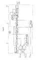
- Fig. 2 is a functional block diagram showing details of processing performed by the vehicle controller 64.
- the vehicle controller 64 has the functions of an estimator (observer) 64a, revolution speed table data 64b, multipliers 64c and 64d, a converter 64e, engine output table data 64f, a subtractor 64g, and a computing unit 64h.
- the estimator 64a stores an equation of motion about the swash plate 2a of the hydraulic pump 2 as a program, and calculates virtually the displacement of the hydraulic pump 2 (called the pump displacement hereunder where appropriate) by use of the delivery pressure of the hydraulic pump 2, which is detected with the pressure sensor 40, the output pressure Pgr of the engine revolution speed detection valve 13, which is detected with the pressure sensor 41, the output pressure Pls of the differential pressure reducing valve 11, which is detected with the pressure sensor 42, and the equation of motion.
- the equation of motion about the swash plate 2a covers the movements attributed to horsepower control of the hydraulic pump 2 and to flow rate control under load sensing control (to be discussed later).
- the revolution speed table data 64b inputs the output pressure Pgr of the engine revolution speed detection valve 13, which is detected with the pressure sensor 41, and calculates the revolution speed of the hydraulic pump 2 (called the pump revolution speed hereunder where appropriate) by referencing the output pressure Pgr of the engine revolution speed detection valve 13 against previously stored relations between the absolute pressure Pgr and the engine revolution speed. Because the engine revolution speed detection valve 13 outputs the absolute pressure Pgr in accordance with the delivery flow rate of the pilot pump 30, it is possible conversely to calculate the delivery flow rate of the pilot pump 30 (i.e., revolution speed of the pilot pump 30) from the absolute pressure Pgr, thereby obtaining the pump revolution speed.
- the multipliers 64c and 64d and the converter 64e make up a pump power calculation unit 64j that calculates the power need of the hydraulic pump 2 by use of the pump displacement calculated virtually with the estimator 64a and the delivery pressure of the hydraulic pump 2, which is detected with the pressure sensor 40.
- the multiplier 64c multiplies the obtained pump displacement by the pump revolution speed to calculate the flow rate delivered by the hydraulic pump 2 (called the pump flow rate hereunder where appropriate).
- the multiplier 64d multiplies the pump flow rate by the delivery pressure of the hydraulic pump 2 (called the pump pressure hereunder where appropriate), which is detected with the pressure sensor 40 to calculate the power need of the hydraulic pump 2 (called the pump power need hereunder).
- the engine output table data 64f inputs the pump revolution speed calculated by the revolution speed table data 64b, and calculates the output of the engine 1 (called the engine output hereunder where appropriate) by referencing the pump revolution speed against previously stored output horsepower characteristics of the engine 1. If the revolution speed of the hydraulic pump 2 is different here from the revolution speed of the engine 1 due to the speed reduction ratio of the power distributor 70, the difference between the revolution speeds is compensated with the converter 64e.
- the pump power need calculated with the multipliers 64c and 64d (pump power calculation unit 64j) and the engine output calculated with the engine output table data 64f are horsepower values. Alternatively, these values may be torque values. In this case, the multiplier 64c is not needed, and the engine output table data 64f need only store the output torque characteristics of the engine 1.
- the subtractor 64g subtracts the pump power need from the calculated engine output.
- the computing unit 64h determines how to switch the motor-generator functionally on the basis of the result of "engine output” minus "pump power need” as calculated with the subtractor 64g. Specifically, if “engine output” minus “pump power need” minus Pm is equal to or larger than ( ⁇ ) 0, that means the engine output has some margin to spare. In that case, the computing unit 64h outputs the control signal to the converter 61 so that the motor-generator 60 is to be used as a generator. Conversely, if "engine output” minus “pump power need” minus Pm is less than ( ⁇ ) 0, that means the engine output has no margin to spare. In this case, the computing unit 64h outputs the control signal to the converter 61 so that the motor-generator 60 is to be used as a motor.
- Pm stands for a margin of "pump power need” with regard to "engine output,” the margin being set to an appropriate value in advance.
- Fig. 3A is a block diagram showing some details of the estimator 64a.
- Figs. 3B and 3C are each a partially magnified view of a part of Fig. 3A .
- the estimator 64a is made up of a calculation unit 81 which inputs the output pressure Pgr of the engine revolution speed detection valve 13, which is detected with the pressure sensor 41 and the output pressure Pls of the differential pressure reducing valve 11, which is detected with the pressure sensor 42, and calculates the pressure inside the LS control piston 12c on the basis of a hydraulic model; and a calculation unit 82 which inputs the pump pressure detected with the pressure sensor 40 and, by use of the pressure inside the LS control piston 12c obtained with the calculation unit 81, calculates the pump displacement by establishing the equation of motion about the swash plate 2a on the basis of a typical dynamic model involving the sum of moments working on the rotating center of the swash plate 2a.
- Fig. 3B is a magnified view of the calculation unit 81
- Fig. 3C is a magnified view of the calculation unit 82.
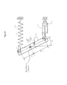
- Fig. 3D is a diagram for explaining the typical dynamic model used in the calculation by the estimator 64a and the parameters for use with that model.
- Fig. 3D shows schematically (using the typical dynamic mode) the structure of a swash plate tilting angle adjusting unit for the hydraulic pump 2.
- the swash plate of the hydraulic pump 2 is indicated by use of a rectangular bar-shaped member 2a.
- the calculation unit 81 is made up of sub-calculation units 81a through 81f.
- the calculation unit 81 calculates the pressure inside the LS control piston 12c from the output pressure Pgr of the engine revolution speed detection valve 13 (called the Pgr pressure hereunder), which is detected with the pressure sensor 41, and from the output pressure Pls of the differential pressure reducing valve 11 (called the Pls pressure hereunder), which is detected with the pressure sensor 42, as described below.
- the sub-calculation unit 81a calculates the pressure difference between the Pgr pressure and the Pls pressure and, by use of the differential pressure, calculates a meter-in opening area APA and a meter-out opening area AAT of the LS control valve 12b.
- the Pgr pressure and the Pls pressure are led to the opposed pressure receiving portions 12d and 12e of the LS control valve 12b, respectively.
- the LS control valve 12b performs its stroke in accordance with the pressure difference between the Pgr pressure and the Pls pressure in order to vary a meter-in throttle opening area (meter-in opening area APA) and a meter-out throttle opening area (meter-out opening area AAT).
- the meter-in throttle is a throttle on a passage that connects the pump port P with the actuator port A of the LS control valve 12b
- the meter-out throttle is a throttle on a passage that connects the actuator port A with the tank port T of the LS control valve 12b.
- the pump port P is connected to the pilot hydraulic line 31b
- the actuator port A is connected to the LS control piston 12c
- the tank port T is connected to the tank T.
- the vehicle controller 64 stores in advance the relations of the meter-in opening area APA and those of the meter-out opening area AAT with regard to the pressure difference between the Pgr pressure and the Pls pressure.
- the sub-calculation unit 81a obtains the meter-in opening area APA and the meter-out opening area AAT by referencing the calculated pressure difference value against these relations.
- the sub-calculation unit 81b calculates the rate of flow into the LS control piston 12c via the meter-in throttle of the LS control valve 12b by use of the meter-in opening area APA calculated with the sub-calculation unit 81a, a previously stored pressure (constant value) of the pilot hydraulic line 31b, and a pressure PCP inside the LS control piston 12c (internal calculated value, to be discussed later).
- the sub-calculation unit 81b obtains the differential pressure across the meter-in throttle of the LS control valve 12b by subtracting the pressure PCP inside the LS control piston 12c (internal calculated value) from the pressure (constant value) of the pilot hydraulic line 31b. The sub-calculation unit 81b then applies to the expression (1) above the differential pressure, the meter-in opening area APA calculated with the sub-calculation unit 81a, the density p of hydraulic fluid, and the coefficient of contraction C PA of the meter-in throttle, thereby obtaining the flow rate into the LS control valve 12b via the meter-in throttle.
- the sub-calculation unit 81c calculates the rate of flow out of the LS control piston 12c via the meter-out throttle of the LS control valve 12b by use of the meter-out opening area AAT calculated with the sub-calculation unit 81a and the pressure PCP inside the LS control piston 12c (internal calculated value, to be discussed later). If the pressure of the tank T is assumed to be zero, the differential pressure across the meter-out throttle becomes equal to the pressure PCP inside the LS control piston 12c.
- the sub-calculation unit 81d calculates the rate of flow generated by contraction and extension of the LS control piston 12c itself by multiplying an angular velocity of the swash plate (internal calculated value, to be discussed later) by the pressure-receiving area A CP of the LS control piston 12c.
- the sub-calculation unit 81e calculates a total flow rate by adding up the rates of the flow into and out of the LS control piston 12c calculated with the sub-calculation units 81b, 81c and 81d.
- the sub-calculation unit 81f multiples the total flow rate calculated with the sub-calculation unit 81e by the bulk modulus B divided by the internal volume V CP of the LS control piston 12c, before integrating the resulting value to calculate the pressure PCP inside the LS control piston 12c.
- the calculation unit 82 is made up of sub-calculation units 82a through 82h.
- the calculation unit 82 calculates the pump displacement from the pump pressure detected with the pressure sensor 40 and from the pressure inside the LS control piston 12c calculated with the calculation unit 81, as described below.
- the sub-calculation unit 82a calculates the force Fcp received by the swash plate 2a from the LS control piston 12c by multiplying the pressure PCP inside the LS control piston 12c calculated with the calculation unit 81 by the pressure-receiving area of the LS control piston 12c.
- the sub-calculation unit 82a further calculates the angular moment of the swash plate 2a under the pressure PCP inside the LS control piston 12c by multiplying the force F CP by the distance L CP between the point of action of the force F CP received by the swash plate 2a from the LS control piston 12c on the one hand, and the rotating center of the swash plate 2a on the other hand.
- the sub-calculation unit 82b calculates the resultant force (i.e., force received by the swash plate 2a from the torque control piston 12a) F P received by the swash plate 2a from each of the pistons of the piston cylinders on the basis of the pump pressure.
- the sub-calculation unit 82b further multiplies the resultant force F P by the distance L P between the point of action of the resultant force F P received by the swash plate 2a on the one hand and the rotating center of the swash plate 2a on the other hand, thereby calculating the angular moment of the swash plate 2a under the pump pressure Pd.
- the vehicle controller 64 stores in advance the relations between the pump pressure and the resultant force F P received by the swash plate 2a from each of the pistons of the piston cylinders.
- the sub-calculation unit 82b obtains the resultant force Fp by referencing the pump pressure against these relations.
- the sub-calculation unit 82c calculates the force F K received by the swash plate 2a from the torque control spring 12f by multiplying the tilting angle ⁇ of the swash plate 2a (internal calculated value, to be discussed later) by a spring constant k of the torque control spring 12f.
- the sub-calculation unit 82c further multiplies the force F K by the distance L K between the point of action of the force F K received by the swash plate 2a on the one hand and the rotating center of the swash plate 2a on the other hand, thereby calculating the angular moment of the swash plate 2a under biasing force of the torque control spring 12f.
- the sub-calculation unit 82d calculates a total moment by adding up the moments working around the rotating center of the swash plate 2a and calculated with the sub-calculation units 82a, 82b and 82c.
- the sub-calculation unit 82e calculates the moment of resistance working around the rotating center of the swash plate 2a by multiplying the angular velocity of the swash plate (internal calculated value, to be discussed later) by the coefficient c of viscosity of the swash plate. The sub-calculation unit 82e further subtracts the movement of resistance from the total moment calculated with the sub-calculation unit 82d, thereby calculating the moment working around the rotating center of the swash plate 2a.
- the sub-calculation unit 82f multiplies the moment working around the rotating center of the swash plate 2a and calculated with the sub-calculation unit 82e, by 1 divided by the moment of inertia I SW around the rotating center of the swash plate 2a, before integrating the resulting value to calculate the angular velocity of the swash plate 2a.
- the sub-calculation unit 82g calculates the tilting angle of the swash plate 2a by integrating the angular velocity of the swash plate 2a calculated with the sub-calculation unit 82f.
- the sub-calculation unit 82h calculates the pump displacement from the tilting angle of the swash plate 2a obtained with the sub-calculation unit 82g.
- the vehicle controller 64 stores in advance the relations between the tilting angle of the swash plate 2a and the pump displacement.
- the sub-calculation unit 82h obtains the pump displacement by referencing the tilting angle of the swash plate 2a against these relations.
- the flow control valves 6a, 6b, 6c, ... are in neutral position so that the delivery fluid from the hydraulic pump 2 are not supplied to the actuators 3a, 3b, 3c, etc. Also, when the flow control valves 6a, 6b, 6c, ... are in neutral position, the maximum load pressure detected with the shuttle valves 9a, 9b, 9c, ... is the tank pressure.
- the unloading valve 15 is opened to provide control so that the delivery pressure of the hydraulic pump 2 does not become higher than the unloading pressure Pun.
- the LS control valve 12b is switched to the right side position shown in the figure. This allows the pressure of the pilot hydraulic power source 33 to be led to the LS control piston 12c so that the hydraulic pump 2 is controlled to have its tilting angle reduced.
- the hydraulic pump 2 has a stopper (not shown) that prescribes the minimum tilting angle of the pump 2. The hydraulic pump 2 is held at the minimum tilting angle as prescribed by the stopper, thus delivering a minimum flow rate.
- the flow control valve 6b is switched to supply the hydraulic fluid to the boom cylinder 3b, which drives the boom cylinder 3b.
- the flow rate through the flow control valve 6b is determined by the opening area of the meter-in throttle and the differential pressure across the meter-in throttle of the valve 6b. Because the differential pressure across the meter-in throttle is controlled by the pressure compensating valve 7b to become equal to the output pressure of the differential pressure reducing valve 11, the flow rate through the flow control valve 6b (hence the driving speed of the boom cylinder 3b) is controlled in accordance with the operation amount of the control lever (demanded flow rate).
- the delivery pressure of the hydraulic pump 2 drops temporarily.
- the output pressure of the engine revolution detection valve 13 and that of the differential pressure reducing valve 11 are led to the LS control valve 12b of the hydraulic pump 2, so that if the delivery pressure of the hydraulic pump 2 drops to let the output pressure of the differential pressure reducing valve 11 become lower than the output pressure of the engine revolution speed detection valve 13, the LS control valve 12b is switched to the left side position shown in the figure. This provides control so that the LS control piston 12c is connected with the tank T to increase the tilting angle of the hydraulic pump 2, thereby raising the delivery flow rate of the hydraulic pump 2.
- the rise in the delivery flow rate of the hydraulic pump 2 continues until the output pressure of the differential pressure reducing valve 11 becomes equal to the output pressure of the engine revolution speed detection valve 13.
- the above series of operations provides control so that the delivery pressure of the hydraulic pump 2 becomes higher than the maximum load pressure just by the output pressure (target differential pressure) of the engine revolution speed detection valve 13.
- the boom cylinder 3b is supplied with the flow rate (demanded flow rate) corresponding to the operation amount of the control lever under so-called load sensing control.
- the load pressure of the boom cylinder 3b is led as the maximum load pressure to the unloading valve 15 so that the cracking pressure of the unloading valve 15 (i.e., pressure at which the unloading valve 15 starts to open) is raised in keeping with the load pressure of the boom cylinder 3b.
- This allows the delivery fluid of the hydraulic pump 2 to be supplied to the boom cylinder 3b without the unloading valve 15 getting opened.
- the unloading valve 15 is opened to let the delivery fluid of the hydraulic pump 2 partially return to the tank, whereby the transient rise in the delivery pressure of the hydraulic pump 2 is prevented.
- load sensing control is performed so that the delivery pressure of the hydraulic pump 2 becomes higher than the maximum load pressure just by the output pressure of the engine revolution speed detection valve 13 (target differential pressure) as in the case of a single control lever being operated.
- the boom cylinder 3b and the arm cylinder 3c are supplied with the flow rates reflecting the operation amounts of the control levers (demanded flow rates), whereby the boom cylinder 3b and the arm cylinder 3c are driven.
- the differential pressure across each of the meter-in throttles of the flow control valves 6b and 6c is controlled by the pressure compensating valves 7b and 7c to become equal to the output pressure of the differential pressure reducing valve 11 (i.e., differential pressure between the delivery pressure of the hydraulic pump 2 and the maximum load pressure). For this reason, regardless of the magnitude of their load pressures, the boom cylinder 3b and arm cylinder 11 are supplied with hydraulic fluid in proportion to the opening area of each of the meter-in throttles of the flow control valves 6b and 6c.
- the output pressure of the differential pressure reducing valve 11 (differential pressure between the delivery pressure of the hydraulic pump 2 and the maximum load pressure) drops in keeping with the degree of saturation, and the target compensation differential pressure of the pressure compensating valves 7b and 7c is reduced accordingly.
- the delivery flow rate of the hydraulic pump 2 can be redistributed in proportion to the opening area of each of the meter-in throttles of the flow control valves 6b and 6c.
- the vehicle controller 64 performs the processes described below to switch the motor-generator 60 either to motor function or to generator function.
- the delivery pressure of the hydraulic pump 2, which is detected with the pressure sensor 40, the output pressure Pgr of the engine revolution speed detection valve 13, which is detected with the pressure sensor 41, and the output pressure Pls of the differential pressure reducing valve 11, which is detected with the pressure sensor 42, are input to the estimator 64a.
- the estimator 64a calculates virtually the displacement of the hydraulic pump 2 in accordance with the principles explained above by use of Figs. 3A through 3D .
- the output pressure Pgr of the engine revolution speed detection valve 13, which is detected with the pressure sensor 41 is input to the revolution speed table data 64b.
- the revolution speed table data 64b calculates the pump revolution speed.
- the pump displacement and the pump revolution speed thus calculated are subjected to multiplication by the multiplier 64c whereby the delivery flow rate of the hydraulic pump 2 is calculated.
- the delivery pressure of the hydraulic pump 2, which is detected with the pressure sensor 40, and the pump flow rate calculated above are subjected to multiplication by the multiplier 64d whereby the power need of the hydraulic pump 2 (pump power need) is calculated.
- the pump revolution speed calculated with the revolution speed table data 64b is input to the output table data 64f whereby the output of the engine 1 (engine output) is calculated.
- the revolution speed of the hydraulic pump 2 is different from the revolution speed of the engine 1 due to the speed reduction ratio of the power distributor 70, the difference between the revolution speeds is compensated with the converter 64e.
- the subtractor 64g performs a comparison between the engine output and the pump power need calculated as described above. Later, if the comparison reveals that "engine output” minus “pump power need” minus Pm is equal to or larger than ( ⁇ ) zero, this means that there is engine output to spare. In this case, the computing unit 64h outputs the control signal to the converter 61 so that the motor-generator 60 is to be used as a generator. The motor-generator 60 thus caused to run as the generator generates power that is stored into the battery 62. Conversely, if the comparison reveals that "engine output” minus “pump power need” minus Pm is less than ( ⁇ ) zero, this means that there is no engine output to spare regarding the pump power need.
- the computing unit 64h outputs the control signal to the converter 61 so that the motor-generator 60 is to be used as a motor.
- the motor-generator 60 thus caused to run as the motor operates by use of power from the battery 62 to assist the engine 1.
- excess engine output is accumulated as electric energy so as to save energy.
- the stored electric energy is discharged to drive the motor-generator 60, whereby the necessary pump power is maintained.
- the displacement of the hydraulic pump 2 can be estimated without resorting to sensors to detect the titling angle of the swash plate of the hydraulic pump 2. There is no need to install tilting angle sensors.
- the hybrid system can be mounted easily on small-size hydraulic excavators such as mini-excavators having often-insufficient installation space.
- the pump revolution speed or the engine revolution speed is calculated from the output pressure Pgr of the engine revolution speed detection valve 13, which is detected with the pressure sensor 41.
- the power need of the hydraulic pump 2 can be calculated without the use of sensors to detect the tilting angle of the swash plate 2a of the hydraulic pump 2 and the revolution speed of the engine 1.
- the hybrid system can be mounted easily on small-size hydraulic excavators such as mini-excavators with their engines not equipped with sensors to detect the revolution speed because of size restrictions.
Landscapes
- Engineering & Computer Science (AREA)
- General Engineering & Computer Science (AREA)
- Mining & Mineral Resources (AREA)
- Civil Engineering (AREA)
- Structural Engineering (AREA)
- Mechanical Engineering (AREA)
- Fluid Mechanics (AREA)
- Physics & Mathematics (AREA)
- Chemical & Material Sciences (AREA)
- Combustion & Propulsion (AREA)
- Transportation (AREA)
- Analytical Chemistry (AREA)
- Operation Control Of Excavators (AREA)
- Fluid-Pressure Circuits (AREA)
Applications Claiming Priority (2)
| Application Number | Priority Date | Filing Date | Title |
|---|---|---|---|
| JP2012104987 | 2012-05-01 | ||
| PCT/JP2013/057781 WO2013164928A1 (ja) | 2012-05-01 | 2013-03-19 | ハイブリッド式作業機械 |
Publications (2)
| Publication Number | Publication Date |
|---|---|
| EP2845954A1 true EP2845954A1 (de) | 2015-03-11 |
| EP2845954A4 EP2845954A4 (de) | 2016-04-06 |
Family
ID=49514329
Family Applications (1)
| Application Number | Title | Priority Date | Filing Date |
|---|---|---|---|
| EP13785272.9A Withdrawn EP2845954A4 (de) | 2012-05-01 | 2013-03-19 | Hybridarbeitsmaschine |
Country Status (6)
| Country | Link |
|---|---|
| US (1) | US9702379B2 (de) |
| EP (1) | EP2845954A4 (de) |
| JP (1) | JP5952897B2 (de) |
| KR (1) | KR102033954B1 (de) |
| CN (1) | CN104285014B (de) |
| WO (1) | WO2013164928A1 (de) |
Families Citing this family (13)
| Publication number | Priority date | Publication date | Assignee | Title |
|---|---|---|---|---|
| JP5878811B2 (ja) * | 2012-04-10 | 2016-03-08 | 日立建機株式会社 | 建設機械の油圧駆動装置 |
| US10358797B2 (en) * | 2015-08-14 | 2019-07-23 | Parker-Hannifin Corporation | Boom potential energy recovery of hydraulic excavator |
| JP6453736B2 (ja) * | 2015-09-24 | 2019-01-16 | 株式会社日立建機ティエラ | 建設機械の油圧駆動装置 |
| JP6584365B2 (ja) * | 2016-05-13 | 2019-10-02 | 株式会社東芝 | アクチュエータおよび流路構成部 |
| US10989052B2 (en) * | 2017-02-14 | 2021-04-27 | Kolberg-Pioneer, Inc. | Apparatus and method for a dual power system |
| JP6789843B2 (ja) * | 2017-02-17 | 2020-11-25 | ヤンマーパワーテクノロジー株式会社 | 油圧機械の制御装置 |
| JP6858723B2 (ja) * | 2018-03-28 | 2021-04-14 | 日立建機株式会社 | ホイールローダ |
| JP6940447B2 (ja) * | 2018-03-28 | 2021-09-29 | 株式会社日立建機ティエラ | 建設機械の油圧駆動装置 |
| JP6934454B2 (ja) * | 2018-06-25 | 2021-09-15 | 日立建機株式会社 | 建設機械 |
| CN111306295B (zh) * | 2018-12-12 | 2021-06-29 | 上海汽车集团股份有限公司 | 混合动力变速箱液压控制系统以及车辆 |
| CN113994092B (zh) * | 2019-09-24 | 2024-06-04 | 株式会社日立建机Tierra | 电动式液压作业机械 |
| US20230035718A1 (en) * | 2020-02-19 | 2023-02-02 | Hanon Systems | Method for controlling swash plate compressor and swash plate compressor |
| CN114909280B (zh) * | 2022-04-07 | 2024-05-17 | 潍柴动力股份有限公司 | 基于多源信息反馈优化的液压泵控制方法及系统 |
Family Cites Families (20)
| Publication number | Priority date | Publication date | Assignee | Title |
|---|---|---|---|---|
| JP3910280B2 (ja) | 1996-11-15 | 2007-04-25 | 日立建機株式会社 | 油圧駆動装置 |
| US6105367A (en) | 1996-11-15 | 2000-08-22 | Hitachi Construction Machinery Co. Ltd. | Hydraulic drive system |
| DE19709475A1 (de) * | 1997-03-07 | 1998-09-10 | Rexroth Mannesmann Gmbh | Hydraulische Hubvorrichtung |
| JPH11218102A (ja) * | 1997-11-11 | 1999-08-10 | Komatsu Ltd | 圧油供給装置 |
| JP4475767B2 (ja) * | 2000-08-03 | 2010-06-09 | 株式会社小松製作所 | 作業用車両 |
| JP3833573B2 (ja) | 2002-06-06 | 2006-10-11 | 新キャタピラー三菱株式会社 | ハイブリッド式建設機械 |
| DE10304918A1 (de) * | 2003-02-07 | 2004-08-19 | Zf Friedrichshafen Ag | Antriebsstrang für ein Mobilfahrzeug |
| US20070227135A1 (en) * | 2006-03-30 | 2007-10-04 | Caterpillar Inc. | Integrated load-sensing hydraulic system |
| US9032725B2 (en) * | 2006-10-06 | 2015-05-19 | Volvo Construction Equipment Ab | Method for operating a working machine and a working machine |
| CN201071519Y (zh) * | 2007-05-18 | 2008-06-11 | 浙江工业大学 | 原动机输出扭矩均衡控制装置 |
| US7748279B2 (en) * | 2007-09-28 | 2010-07-06 | Caterpillar Inc | Hydraulics management for bounded implements |
| US8244438B2 (en) * | 2008-01-31 | 2012-08-14 | Caterpillar Inc. | Tool control system |
| JP5030864B2 (ja) | 2008-05-30 | 2012-09-19 | カヤバ工業株式会社 | ハイブリッド建設機械の制御装置 |
| JP5135169B2 (ja) * | 2008-10-31 | 2013-01-30 | 日立建機株式会社 | 建設機械の油圧駆動装置 |
| US8739906B2 (en) * | 2009-06-19 | 2014-06-03 | Sumitomo Heavy Industries, Ltd. | Hybrid-type construction machine and control method for hybrid-type construction machine |
| KR20110077061A (ko) * | 2009-12-30 | 2011-07-07 | 볼보 컨스트럭션 이큅먼트 에이비 | 오픈센터 방식의 굴삭기용 유압시스템의 선회모터 제어방법 |
| JP5718611B2 (ja) * | 2010-10-19 | 2015-05-13 | ニチユ三菱フォークリフト株式会社 | 車両、及びその制御方法 |
| EP2662576B1 (de) * | 2011-01-06 | 2021-06-02 | Hitachi Construction Machinery Tierra Co., Ltd. | Hydraulischer antrieb einer arbeitsmaschine mit einer raupenlaufvorrichtung |
| JP5585488B2 (ja) * | 2011-02-17 | 2014-09-10 | コベルコ建機株式会社 | ハイブリッド建設機械の動力源装置 |
| JP6019956B2 (ja) * | 2012-09-06 | 2016-11-02 | コベルコ建機株式会社 | ハイブリッド建設機械の動力制御装置 |
-
2013
- 2013-03-19 EP EP13785272.9A patent/EP2845954A4/de not_active Withdrawn
- 2013-03-19 CN CN201380022839.9A patent/CN104285014B/zh not_active Expired - Fee Related
- 2013-03-19 WO PCT/JP2013/057781 patent/WO2013164928A1/ja not_active Ceased
- 2013-03-19 US US14/387,278 patent/US9702379B2/en not_active Expired - Fee Related
- 2013-03-19 JP JP2014513345A patent/JP5952897B2/ja active Active
- 2013-03-19 KR KR1020147029723A patent/KR102033954B1/ko not_active Expired - Fee Related
Also Published As
| Publication number | Publication date |
|---|---|
| EP2845954A4 (de) | 2016-04-06 |
| CN104285014A (zh) | 2015-01-14 |
| KR20150013136A (ko) | 2015-02-04 |
| CN104285014B (zh) | 2016-11-16 |
| KR102033954B1 (ko) | 2019-11-08 |
| JP5952897B2 (ja) | 2016-07-13 |
| WO2013164928A1 (ja) | 2013-11-07 |
| US20150040553A1 (en) | 2015-02-12 |
| US9702379B2 (en) | 2017-07-11 |
| JPWO2013164928A1 (ja) | 2015-12-24 |
Similar Documents
| Publication | Publication Date | Title |
|---|---|---|
| US9702379B2 (en) | Hybrid working machine | |
| JP6867551B2 (ja) | 電動式油圧作業機械の油圧駆動装置 | |
| KR101992510B1 (ko) | 건설 기계 | |
| EP2738397B1 (de) | Baumaschine | |
| US11022153B2 (en) | Hydraulic apparatus comprising synthetically commutated machine, and operating method | |
| KR101953418B1 (ko) | 전동식 유압 작업 기계의 유압 구동 장치 | |
| JP6549543B2 (ja) | 作業機械の油圧駆動装置 | |
| KR101876895B1 (ko) | 건설 기계의 유압 구동 장치 | |
| KR101972426B1 (ko) | 제어 시스템, 작업 기계, 및 제어 방법 | |
| CN104619996B (zh) | 电动式液压作业机械的液压驱动装置 | |
| US10676898B2 (en) | Hydraulic drive system of work machine | |
| US9086081B2 (en) | Hydraulic control system having swing motor recovery | |
| CN113994092B (zh) | 电动式液压作业机械 | |
| EP2949948A1 (de) | Hydraulische antriebsvorrichtung für eine baumaschine | |
| CN107850094B (zh) | 控制系统、作业机械及控制方法 | |
| JPWO2019064555A1 (ja) | 作業機械の油圧駆動装置 | |
| JP2012241742A (ja) | 建設機械の油圧駆動装置 | |
| JP2016061387A5 (de) | ||
| JP6082690B2 (ja) | 建設機械の油圧駆動装置 |
Legal Events
| Date | Code | Title | Description |
|---|---|---|---|
| PUAI | Public reference made under article 153(3) epc to a published international application that has entered the european phase |
Free format text: ORIGINAL CODE: 0009012 |
|
| 17P | Request for examination filed |
Effective date: 20141201 |
|
| AK | Designated contracting states |
Kind code of ref document: A1 Designated state(s): AL AT BE BG CH CY CZ DE DK EE ES FI FR GB GR HR HU IE IS IT LI LT LU LV MC MK MT NL NO PL PT RO RS SE SI SK SM TR |
|
| AX | Request for extension of the european patent |
Extension state: BA ME |
|
| DAX | Request for extension of the european patent (deleted) | ||
| RA4 | Supplementary search report drawn up and despatched (corrected) |
Effective date: 20160308 |
|
| RIC1 | Information provided on ipc code assigned before grant |
Ipc: B60K 6/48 20071001ALI20160302BHEP Ipc: E02F 9/20 20060101AFI20160302BHEP Ipc: E02F 9/22 20060101ALI20160302BHEP Ipc: F15B 11/00 20060101ALI20160302BHEP |
|
| RAP1 | Party data changed (applicant data changed or rights of an application transferred) |
Owner name: HITACHI CONSTRUCTION MACHINERY TIERRA CO., LTD. |
|
| STAA | Information on the status of an ep patent application or granted ep patent |
Free format text: STATUS: THE APPLICATION HAS BEEN WITHDRAWN |
|
| 18W | Application withdrawn |
Effective date: 20180706 |
|
| RIC1 | Information provided on ipc code assigned before grant |
Ipc: E02F 9/20 20060101AFI20160302BHEP Ipc: F15B 11/00 20060101ALI20160302BHEP Ipc: B60K 6/48 20071001ALI20160302BHEP Ipc: E02F 9/22 20060101ALI20160302BHEP |