EP2846100B1 - Système de refroidissement et d'échappement destiné à un four de cuisson - Google Patents
Système de refroidissement et d'échappement destiné à un four de cuisson Download PDFInfo
- Publication number
- EP2846100B1 EP2846100B1 EP13183703.1A EP13183703A EP2846100B1 EP 2846100 B1 EP2846100 B1 EP 2846100B1 EP 13183703 A EP13183703 A EP 13183703A EP 2846100 B1 EP2846100 B1 EP 2846100B1
- Authority
- EP
- European Patent Office
- Prior art keywords
- inlet
- cooling
- exhaust system
- fan shroud
- discharging channel
- Prior art date
- Legal status (The legal status is an assumption and is not a legal conclusion. Google has not performed a legal analysis and makes no representation as to the accuracy of the status listed.)
- Not-in-force
Links
- 238000001816 cooling Methods 0.000 title claims description 85
- 238000010411 cooking Methods 0.000 title claims description 42
- 238000007599 discharging Methods 0.000 claims description 59
- 230000003068 static effect Effects 0.000 description 16
- 238000010586 diagram Methods 0.000 description 11
- 238000005265 energy consumption Methods 0.000 description 4
- 239000000284 extract Substances 0.000 description 2
- 238000000197 pyrolysis Methods 0.000 description 2
- 241000555745 Sciuridae Species 0.000 description 1
- 238000010438 heat treatment Methods 0.000 description 1
- 230000006698 induction Effects 0.000 description 1
- 238000005381 potential energy Methods 0.000 description 1
- 238000013022 venting Methods 0.000 description 1
Images



Classifications
-
- F—MECHANICAL ENGINEERING; LIGHTING; HEATING; WEAPONS; BLASTING
- F24—HEATING; RANGES; VENTILATING
- F24C—DOMESTIC STOVES OR RANGES ; DETAILS OF DOMESTIC STOVES OR RANGES, OF GENERAL APPLICATION
- F24C15/00—Details
- F24C15/20—Removing cooking fumes
- F24C15/2007—Removing cooking fumes from oven cavities
-
- F—MECHANICAL ENGINEERING; LIGHTING; HEATING; WEAPONS; BLASTING
- F24—HEATING; RANGES; VENTILATING
- F24C—DOMESTIC STOVES OR RANGES ; DETAILS OF DOMESTIC STOVES OR RANGES, OF GENERAL APPLICATION
- F24C15/00—Details
- F24C15/20—Removing cooking fumes
- F24C15/2042—Devices for removing cooking fumes structurally associated with a cooking range e.g. downdraft
-
- F—MECHANICAL ENGINEERING; LIGHTING; HEATING; WEAPONS; BLASTING
- F24—HEATING; RANGES; VENTILATING
- F24C—DOMESTIC STOVES OR RANGES ; DETAILS OF DOMESTIC STOVES OR RANGES, OF GENERAL APPLICATION
- F24C15/00—Details
- F24C15/006—Arrangements for circulation of cooling air
Definitions
- the present invention relates to a cooling and exhaust system, in particular for a cooking oven, according to the preamble of claim 1. Further, the present invention relates to a cooking oven with a cooling and exhaust system.
- Cooling and exhaust systems usually operate with either an axial fan or cross-flow fan.
- the cooling and exhaust systems with the axial fan provide good results in the high efficiency of a fan shroud.
- Said fan shroud is able to generate high pressure and an air flow throughout the cooling and exhaust system.
- the axial fan is expensive and results in high costs of the whole cooling and exhaust system.
- the cooling and exhaust systems with the cross-flow fan causes only low costs and a good efficiency.
- the cooling and exhaust system with the cross-flow fan is installed above an oven cavity of the cooking oven and directly on a driving plate.
- a discharging channel of the cooling and exhaust system extends from the rear portion to a front portion of the cooking oven. Vapour and/or hot air are eliminated through the lower part of a control panel of the cooking oven, but sometimes through the upper part of said control panel.
- FIG 6 illustrates a schematic sectional side view of the cooling and exhaust system 40 and a corresponding pressure-space-diagram according to the prior art.
- the upper picture represents the cooling and exhaust system 40, while the pressure-space-diagram is shown by the lower picture.
- the cooling and exhaust system 40 comprises a fan shroud 12 and a discharging channel 14.
- An impeller 16 with a plurality of fan blades 18 is arranged inside the fan shroud 12.
- the rotation axis of the impeller 16 extends perpendicular to the plane of the drawing, and the impeller 16 rotates counterclockwise.
- the fan shroud 12 and the impeller 16 form a cross-flow fan.
- An inlet 42 is arranged above the impeller 16.
- the impeller 16 is driven by an electric motor.
- the impeller 16 rotates in the direction of the action of the forwardly inclined fan blades 18 and generates a strong suction of an air stream from the inlet 42.
- the air stream follows via a path through the fan shroud 12 and the discharging channel 14 to an outlet 24.
- An exhaust pipe 32 is installed in the bottom of the discharging channel 14 and communicates with the ceiling of the oven cavity.
- an air suction and a low pressure zone occurs in the exhaust pipe 32, which extracts the vapours from the oven cavity due to the air stream in the discharging channel 14.
- the vapours follow the same path as the air stream from the inlet 42 to the outlet 24.
- the cooling and exhaust system is provided for cooling the components above the oven cavity on the one hand and eliminating the vapours released from the cavity.
- the pressure-space-diagram in the lower picture of FIG 6 shows the distribution of the static pressure along the cooling and exhaust system 40.
- the static pressure may have positive and negative values.
- the distribution of the static pressure depends on the geometry of the fan shroud 12 and on the inner shapes of the cooling and exhaust system 40.
- Experimental results have shown that the suction pressure remains low around the zone of the exhaust pipe 32 during the operation of the cross-flow fan, since the airflow incident angle relative to the horizontal base plate 30 has a low value.
- the low static pressure in the zone of the exhaust pipe 32 is disadvantageous, since a consistent mass of vapour remains inside the oven cavity. Further, the low static pressure in the zone of the exhaust pipe 32 is disadvantageous for the energy consumption.
- EP 1 566 594 A1 discloses an apparatus for venting a cooking oven.
- the apparatus includes a cross-flow fan arranged in rear portion of the cooking oven and above the oven cavity.
- the apparatus is provided for a cooking operation and for a pyrolysis operation.
- In the cooking operation an air flow is blown from the cross-flow fan through a substantially horizontal upper channel into the inner space of the oven door, wherein the air flow is blown downwards within said inner space of the oven door.
- the air flow In a lower portion of the oven door the air flow is guided to the environment.
- the pyrolysis operation the air flow is sucked from the environment and streams upwards within the inner space of the oven door and through a substantially horizontal lower channel to the cross-flow fan.
- the horizontal upper channel is arranged directly above the horizontal lower channel.
- the horizontal upper channel is connected to an outlet of the cross-flow fan, while the horizontal lower channel is connected to an inlet of said cross-flow fan.
- a further inlet of the cross-flow fan is directly connected to the environment.
- the object of the present invention is achieved by the cooling and exhaust system according to claim 1 and with a cooking oven according to claims 9 or 10.
- the first inlet is arranged in an upper portion of the fan shroud, i.e. above the rotation axis of the impeller, wherein said first inlet is arranged above the discharging channel, and wherein a bottom side of the fan shroud is at least partially open, and wherein a portion of said bottom side is closed or closable by a base plate that can be part of the cooling and exhaust system or of the cooking oven and wherein the position of said base plate is variable, so that an air stream through the cooling and exhaust system follows a path defined by the geometry of the cooling and exhaust system in a predetermined manner.
- the main idea of the present invention is the cooling and exhaust system with two inlets and one outlet, wherein the both inlets are arranged at opposite sides of the fan shroud.
- the inlets suck air from different directions.
- the air is exhausted by the common outlet.
- the structure of two inlets and one outlet allows an efficient operation of the cooling and exhaust system.
- the impeller may be driven by reduced power.
- the first inlet is arranged above the discharging channel. This contributes to a compact structure of the cooling and exhaust system.
- the direction of an air stream through the first inlet is opposite to the direction of the air stream inside the discharging channel.
- the direction of an air stream through the second inlet may be the same as the direction of the air stream inside the discharging channel.
- a bottom side of the fan shroud is at least partially open, wherein a portion of said bottom side is closed or closable by a base plate, and wherein the base plate is either a part of the cooling and exhaust system or of the cooking oven.
- an air stream through the cooling and exhaust system follows a path defined by the geometry of the cooling and exhaust system in a predetermined manner.
- the flow of the air stream through the first inlet is bigger than the flow of the air stream through the second inlet.
- a main air stream is sucked through the first inlet, while the second inlet sucks an additional air stream.
- an exhaust pipe may be arranged in the bottom of the discharging channel, so that the discharging channel is connectable to an oven cavity of the cooking oven.
- the structure of the two inlets, the one outlet and the exhaust pipe allows a high negative static pressure in the discharging channel, so that vapours can be removed from the oven cavity of the cooking oven and exhausted through the discharging channel.
- the impeller is driven by an electric motor energized by alternating or direct current.
- the sum of the air streams through the first inlet and the second inlet is equal to the air stream through the outlet. There are no further inlets and outlets.
- the present invention relates to a cooking oven with the cooling and exhaust system mentioned above.
- the first inlet is provided for sucking air from an upper front portion of the cooking oven.
- the first inlet is provided for sucking air from a space around a control panel of the cooking oven.
- the second inlet is provided for sucking air from the rear side of an oven cavity of the cooking oven.
- the base plate may be arranged above the oven cavity of the cooking oven.
- FIG 1 illustrates a schematic sectional side view of a cooling and exhaust system 10 and a corresponding pressure-space-diagram according to a preferred embodiment of the present invention.
- the cooling and exhaust system 10 is provided for a cooking oven.
- the upper picture in FIG 1 shows the physical cooling and exhaust system 10, while the pressure-space-diagram is shown by the lower picture in FIG 1 .
- the cooling and exhaust system 10 comprises a fan shroud 12 and a discharging channel 14.
- the discharging channel 14 is attached at the fan shroud 12.
- the discharging channel 14 includes an open end opposite to the fan shroud 12.
- the discharging channel 14 extends along a horizontal direction.
- An impeller 16 is arranged inside the fan shroud 12.
- the impeller 16 includes a plurality of fan blades 18.
- the rotation axis of the impeller 16 extends perpendicular to the plane of the drawing in FIG 1 .
- the impeller 16 rotates counterclockwise in FIG 1 .
- the fan blades 18 are inclined in forward direction.
- the fan shroud 12 and the impeller 16 form a cross-flow fan.
- the impeller 16 is driven by an electric motor 26, which is not shown in FIG 1 .
- the impeller 16 generates a tangential air stream inside the fan shroud 12. Said air stream is set forth inside the discharging channel 14 as a substantially straightforward air stream 36.
- the cooling and exhaust system 10 includes a base plate 30 at its bottom. A lower part of the fan shroud 12 is formed by a portion of said base plate 30.
- the cooling and exhaust system 10 includes a first inlet 20, a second inlet 22 and an outlet 24.
- the first inlet 20 is arranged above the junction of the fan shroud 12 and discharging channel 14.
- the second inlet 22 is arranged at the bottom of the fan shroud 12 and at the circumferential side of the impeller 16.
- the outlet 24 is arranged at the open end of the discharging channel 14.
- the first inlet 20 and the second inlet 22 are arranged at opposed circumferential sides of the impeller 16.
- the direction of the air flow at the first inlet 20 is substantially reversed relating to the direction of the air flow at the outlet 24.
- the direction of the air flow at the second inlet 22 is substantially the same as the direction of the air flow at the outlet 24.
- a bigger part of the sucked air stream passes the first inlet 20, while a smaller part of the sucked air stream passes the second inlet 22.
- a large mass of fresh air is sucked by the impeller 16 through the first inlet 12 and creates a main air stream inside the cooling and exhaust system 10.
- said fresh air is sucked from the space around the control panel of the cooking oven, wherein the air around the control panel is replaced by another fresh air pulled into the oven casing from the external environment of the cooking oven.
- the control panel and its components may be cooled down by the air from the external environment.
- the smaller part of the air stream sucked by the impeller 16 passes the second inlet 22.
- the air stream sucked through the second inlet 22 is captured from the rear side of an oven cavity of the cooking oven.
- the air at the rear side of the oven cavity is replaced by fresh air pulled in form the external environment above the cooking oven.
- the air at the rear side of the oven cavity is generated by heating elements of the cooking oven and accumulated at said rear side of the oven cavity.
- the second inlet 22 compensates the difference between the air flows of the outlet 24 and the first inlet 20.
- the mass of the air stream circulating in the cooling and exhaust system 10 has permanently a constant value.
- the sum of both air streams from the first inlet 20 and second inlet 22 form an air stream 36 inside the discharging channel 14.
- the air stream 36 exhausts through the outlet 24 at the open end of the discharging channel 14.
- the air stream from the second inlet 22 deflects the sum of both air streams from the first inlet 20 and second inlet 22, so that the direction of said sum of both air streams has an airflow incident angle 38 with a high value relating to the base plate 30.
- This is a result of Ber-noulli law, in which the sum of the potential energy, kinetic energy and pressure remains constant along a closed aerodynamic channel.
- the air stream from the second inlet 22 contributes to disturbances, a relative low kinetic energy and a relative high negative pressure at the entry of the discharging channel 14.
- An exhaust pipe 32 is arranged in the bottom of the discharging channel 14.
- the exhaust pipe 32 is connected or connectable with a ceiling of the oven cavity.
- the air stream from the second inlet 22 causes the relative high negative pressure above the exhaust pipe 32. This results in a relative high suction force of the air stream 34 through the exhaust pipe 32. Said high suction force causes of a relative big amount of extracted vapours from the oven cavity.
- the vapours follow the same path as the air stream 36 inside the discharging channel 14.
- the cooling and exhaust system 10 is provided for cooling components above the oven cavity on the one hand and eliminating vapours released from the oven cavity.
- the pressure-space-diagram in the lower picture of FIG 1 shows the distribution of the static pressure along the cooling and exhaust system 10.
- the static pressure may have positive and negative values characterized by the plus sign and minus sign, respectively.
- the distribution of the static pressure depends on the geometry of the fan shroud 12 and on the inner shapes of the cooling and exhaust system 10.
- the suction pressure around the zone of the exhaust pipe 32 is relative high during the operation of the cross-flow fan, since the airflow incident angle 38 relative to the horizontal base plate 30 has a high value.
- the high static pressure in the zone of the exhaust pipe 32 is an advantage of the present invention, since a lot of vapour is removed from the oven cavity. Further, the high static pressure in the zone of the exhaust pipe 32 is advantageous for the energy consumption.
- FIG 2 illustrates a schematic perspective view of the cooling and exhaust system 10 according to the preferred embodiment of the present invention.
- FIG 2 clarifies the geometric structure of the cooling and exhaust system 10.
- the discharging channel 14 is shown in front of the fan shroud 12.
- the cooling and exhaust system 10 comprises the fan shroud 12 and the discharging channel 14 attached at said fan shroud 12.
- the outlet 24 is arranged at the open end of the discharging channel 14.
- the impeller 16 is arranged inside the fan shroud 12.
- the fan blades 18 of the impeller 16 are partially visible through the first inlet 20.
- the electric motor 26 is arranged beside the fan shroud 12.
- the electric motor 26 is energized at different voltages.
- the electric motor 26 is energized by an alternating current at voltages from 110 V to 240 V.
- the electric motor 26 may be also energized by direct current.
- the electric power of these electric motors 26 may be vary between 10 W and 45 W.
- the electric power of the electric motor 26 depends on the current requests.
- the electric motor 26 is of a shaded pole type or a squirrel cage type.
- FIG 3 illustrates a schematic perspective view of the cooling and exhaust system 10 according to the preferred embodiment of the present invention.
- the perspective view of FIG 3 shows that side of the fan shroud 12, at which the electric motor 26 is attached.
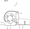
- FIG 4 illustrates a schematic side view of the cooling and exhaust system 10 according to the preferred embodiment of the present invention.
- the discharging channel 14 attached at said fan shroud 12.
- the outlet 24 is arranged at the open end of the discharging channel 14.
- the impeller 16 is arranged inside the fan shroud 12.
- the fan blades 18 of the impeller 16 are partially visible through the first inlet 20.
- the electric motor 26 is arranged beside the fan shroud 12, but not visible in FIG 4 .
- the first inlet 20 and the second inlet 22 are arranged at the opposed circumferential sides of the fan shroud 12.
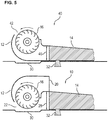
- FIG 5 illustrates a schematic sectional side view of the cooling and exhaust system 10 according to the preferred embodiment of the present invention and a further schematic sectional side view of a cooling and exhaust system 40 according to the prior art.
- An upper picture in FIG 5 shoes the cooling and exhaust system 40 according to the prior art, while a lower upper picture in FIG 5 shows the cooling and exhaust system 10 according to the present invention.
- the cooling and exhaust system 10 according to the preferred embodiment is compared with cooling and exhaust system 40 of the prior art.
- the discharging channels 14 of the present invention and the prior art have different heights 28 and 46.
- a height 28 of the discharging channel 14 of the inventive cooling and exhaust system 10 is bigger than a corresponding height 46 of the discharging channel 14 of the inventive cooling and exhaust system 40 according to the prior art.
- the electric motor 26 should be arranged at a minimum height.
- the distance between the electric motor 26 and the bottom of the base plate 30 should be at least 10 mm.
- the residual dimensions of the both cooling and exhaust systems 10 and 40 are substantially the same.
- FIG 6 illustrates a schematic sectional side view of the cooling and exhaust system 40 and the corresponding pressure-space-diagram according to the prior art.
- the upper picture represents the cooling and exhaust system 40, while the pressure-space-diagram is shown by the lower picture.
- the cooling and exhaust system 40 comprises the fan shroud 12 and the discharging channel 14.
- the impeller 16 with the plurality of fan blades 18 is arranged inside the fan shroud 12.
- the rotation axis of the impeller 16 extends perpendicular to the plane of the drawing.
- the impeller 16 rotates counterclockwise.
- the fan shroud 12 and the impeller 16 form the cross-flow fan.
- An inlet 42 is arranged above the impeller 16.
- the impeller 16 is driven by the electric motor.
- the impeller 16 rotates in the direction of the action of the forwardly inclined fan blades 18 and generates the strong suction of an air stream from the inlet 42.
- the air stream follows via the path through the fan shroud 12 and the discharging channel 14 to the outlet 24.
- the exhaust pipe 32 is installed in the bottom of the discharging channel 14 and communicates with the ceiling of the oven cavity.
- the cooling and exhaust system 40 is provided for cooling the components above the oven cavity on the one hand and eliminating the vapours released from the cavity.
- the pressure-space-diagram in the lower picture of FIG 6 shows the distribution of the static pressure along the cooling and exhaust system 40.
- the static pressure has positive and negative values.
- the distribution of the static pressure depends on the geometry of the fan shroud 12 and on the inner shapes of the cooling and exhaust system 40.
- the suction pressure remains low around the zone of the exhaust pipe 32 during the operation of the cross-flow fan, since the airflow incident angle 44 relative to the horizontal base plate 30 has a low value.
- the low static pressure in the zone of the exhaust pipe 32 is disadvantageous, since a consistent mass of vapour remains inside the oven cavity. Further, the low static pressure in the zone of the exhaust pipe 32 is disadvantageous for the energy consumption.
Landscapes
- Engineering & Computer Science (AREA)
- Chemical & Material Sciences (AREA)
- Combustion & Propulsion (AREA)
- Mechanical Engineering (AREA)
- General Engineering & Computer Science (AREA)
- Structures Of Non-Positive Displacement Pumps (AREA)
Claims (13)
- Système de refroidissement et d'évacuation (10), en particulier pour un four de cuisson, comprenant un capot de refoulement de ventilateur (12), une plaque de base (30) et un canal de décharge (14), dans lequel- une roue (16) est disposée à l'intérieur du capot de refoulement du ventilateur (12), de manière à ce que le capot de refoulement du ventilateur (12) et la roue (16) forment un ventilateur tangentiel,- le canal de décharge (14) est attaché au capot de refoulement du ventilateur (12) et disposé sur le côté circonférentiel de la roue (16),- le canal de décharge (14) comprend une extrémité ouverte disposée en face du capot de refoulement du ventilateur (12),- le canal de décharge (14) s'étend le long d'une direction horizontale,- un premier orifice d'entrée (20) est disposé dans le capot de refoulement du ventilateur (12),- un deuxième orifice d'entrée (22) est disposé dans une partie inférieure du capot de refoulement du ventilateur (12),- le premier orifice d'entrée (20) et le deuxième orifice d'entrée (22) sont disposés sur des côtés circonférentiels opposés de la roue (16) ou près de ceux-ci, et- un orifice de sortie (24) est disposé à l'extrémité ouverte du canal de décharge (14),caractérisé en ce que
le premier orifice d'entrée (20) est disposé dans une partie supérieure du capot de refoulement du ventilateur (12), ledit premier orifice d'entrée (20) étant disposé au-dessus du canal de décharge (14), et un côté inférieur du capot de refoulement du ventilateur (12) étant au moins partiellement ouvert, et une partie dudit côté inférieur étant fermée ou pouvant être fermée par ladite plaque de base (30), et la position de la plaque de base (30) étant variable, de manière à ce qu'un flux d'air à travers le système de refroidissement et d'évacuation (10) suive un chemin défini par la géométrie du système de refroidissement et d'évacuation (10) d'une manière prédéterminée. - Système de refroidissement et d'évacuation selon la revendication 1,
caractérisé en ce que
la direction d'un flux d'air à travers le premier orifice d'entrée (20) est opposée à la direction du flux d'air à l'intérieur du canal de décharge (14). - Système de refroidissement et d'évacuation selon l'une quelconque des revendications précédentes,
caractérisé en ce que
la direction d'un flux d'air à travers le deuxième orifice d'entrée (22) est la même que la direction du flux d'air à l'intérieur du canal de décharge (14) . - Système de refroidissement et d'évacuation selon l'une quelconque des revendications précédentes,
caractérisé en ce que
l'écoulement du flux d'air à travers le premier orifice d'entrée (20) est plus grand que l'écoulement du flux d'air à travers le deuxième orifice d'entrée (22). - Système de refroidissement et d'évacuation selon l'une quelconque des revendications précédentes,
caractérisé en ce que
un tuyau d'évacuation (32) est disposé dans le fond du canal de décharge (14), de manière à ce que le canal de décharge (14) puisse être raccordé à une cavité de four du four de cuisson. - Système de refroidissement et d'évacuation selon l'une quelconque des revendications précédentes,
caractérisé en ce que
la roue (16) est entraînée par un moteur électrique (26) alimenté en courant alternatif ou en courant continu. - Système de refroidissement et d'évacuation selon l'une quelconque des revendications précédentes,
caractérisé en ce que
la somme des flux d'air à travers le premier orifice d'entrée (20) et le deuxième orifice d'entrée (22) est égale au flux d'air à travers l'orifice de sortie (24) . - Four de cuisson avec un système de refroidissement et d'évacuation (10),
caractérisé en ce que
ce four de cuisson comprend le système de refroidissement et d'évacuation (10) selon l'une quelconque des revendications 1 à 8. - Four de cuisson, comprenant une plaque de base (30) qui fait partie de ce four de cuisson et un système de refroidissement et d'évacuation (10) qui comprend un capot de refoulement de ventilateur (12) et un canal de décharge (14), dans lequel- une roue (16) est disposée à l'intérieur du capot de refoulement du ventilateur (12), de manière à ce que le capot de refoulement du ventilateur (12) et la roue (16) forment un ventilateur tangentiel,- le canal de décharge (14) est attaché au capot de refoulement du ventilateur (12) et disposé sur le côté circonférentiel de la roue (16),- le canal de décharge (14) comprend une extrémité ouverte disposée en face du capot de refoulement du ventilateur (12),- le canal de décharge (14) s'étend le long d'une direction horizontale,- un premier orifice d'entrée (20) est disposé dans le capot de refoulement du ventilateur (12),- un deuxième orifice d'entrée (22) est disposé dans une partie inférieure du capot de refoulement du ventilateur (12),- le premier orifice d'entrée (20) et le deuxième orifice d'entrée (22) sont disposés sur des côtés circonférentiels opposés de la roue (16) ou près de ceux-ci, et- un orifice de sortie (24) est disposé à l'extrémité ouverte du canal de décharge (14),caractérisé en ce que
le premier orifice d'entrée (20) est disposé dans une partie supérieure du capot de refoulement du ventilateur (12), ledit premier orifice d'entrée (20) étant disposé au-dessus du canal de décharge (14), et un côté inférieur du capot de refoulement du ventilateur (12) étant au moins partiellement ouvert, et une partie dudit côté inférieur étant fermée ou pouvant être fermée par ladite plaque de base (30) qui fait partie du four de cuisson, et la position de la plaque de base (30) étant variable, de manière à ce qu'un flux d'air à travers le système de refroidissement et d'évacuation (10) suive un chemin défini par la géométrie du système de refroidissement et d'évacuation (10) d'une manière prédéterminée. - Four de cuisson selon la revendication 8 ou 9,
caractérisé en ce que
le premier orifice d'entrée (20) est prévu pour aspirer de l'air d'une partie avant supérieure du four de cuisson. - Four de cuisson selon la revendication 10,
caractérisé en ce que
le premier orifice d'entrée (20) est prévu pour aspirer de l'air d'un espace autour d'un panneau de commande du four de cuisson. - Four de cuisson selon l'une quelconque des revendications 8 à 11,
caractérisé en ce que
le deuxième orifice d'entrée (22) est prévu pour aspirer de l'air du côté arrière d'une cavité de four du four de cuisson. - Four de cuisson selon l'une quelconque des revendications 8 à 12,
caractérisé en ce que
la plaque de base (30) est disposée au-dessus de la cavité du four du four de cuisson.
Priority Applications (4)
| Application Number | Priority Date | Filing Date | Title |
|---|---|---|---|
| EP13183703.1A EP2846100B1 (fr) | 2013-09-10 | 2013-09-10 | Système de refroidissement et d'échappement destiné à un four de cuisson |
| PCT/EP2014/068544 WO2015036274A1 (fr) | 2013-09-10 | 2014-09-02 | Système de refroidissement et d'échappement pour four de cuisson |
| US14/905,684 US20160153666A1 (en) | 2013-09-10 | 2014-09-02 | Cooling and exhaust system for a cooking oven |
| AU2014320631A AU2014320631B2 (en) | 2013-09-10 | 2014-09-02 | Cooling and exhaust system for a cooking oven |
Applications Claiming Priority (1)
| Application Number | Priority Date | Filing Date | Title |
|---|---|---|---|
| EP13183703.1A EP2846100B1 (fr) | 2013-09-10 | 2013-09-10 | Système de refroidissement et d'échappement destiné à un four de cuisson |
Publications (2)
| Publication Number | Publication Date |
|---|---|
| EP2846100A1 EP2846100A1 (fr) | 2015-03-11 |
| EP2846100B1 true EP2846100B1 (fr) | 2018-05-30 |
Family
ID=49209222
Family Applications (1)
| Application Number | Title | Priority Date | Filing Date |
|---|---|---|---|
| EP13183703.1A Not-in-force EP2846100B1 (fr) | 2013-09-10 | 2013-09-10 | Système de refroidissement et d'échappement destiné à un four de cuisson |
Country Status (4)
| Country | Link |
|---|---|
| US (1) | US20160153666A1 (fr) |
| EP (1) | EP2846100B1 (fr) |
| AU (1) | AU2014320631B2 (fr) |
| WO (1) | WO2015036274A1 (fr) |
Families Citing this family (16)
| Publication number | Priority date | Publication date | Assignee | Title |
|---|---|---|---|---|
| USD787041S1 (en) | 2015-09-17 | 2017-05-16 | Whirlpool Corporation | Gas burner |
| US10837651B2 (en) | 2015-09-24 | 2020-11-17 | Whirlpool Corporation | Oven cavity connector for operating power accessory trays for cooking appliance |
| US11777190B2 (en) | 2015-12-29 | 2023-10-03 | Whirlpool Corporation | Appliance including an antenna using a portion of appliance as a ground plane |
| US10145568B2 (en) | 2016-06-27 | 2018-12-04 | Whirlpool Corporation | High efficiency high power inner flame burner |
| US10551056B2 (en) | 2017-02-23 | 2020-02-04 | Whirlpool Corporation | Burner base |
| US10451290B2 (en) | 2017-03-07 | 2019-10-22 | Whirlpool Corporation | Forced convection steam assembly |
| US10660162B2 (en) | 2017-03-16 | 2020-05-19 | Whirlpool Corporation | Power delivery system for an induction cooktop with multi-output inverters |
| CN106958842B (zh) * | 2017-03-16 | 2023-07-21 | 佛山市科思博科技有限公司 | 涡轮动力-静电复合式油烟净化装置 |
| CN107062337B (zh) * | 2017-04-28 | 2023-07-21 | 佛山市科思博科技有限公司 | 静电与涡轮动力结合的油烟净化器 |
| CN108477984B (zh) * | 2018-06-11 | 2024-04-09 | 广东美的厨房电器制造有限公司 | 蒸汽烹饪装置 |
| US10627116B2 (en) | 2018-06-26 | 2020-04-21 | Whirlpool Corporation | Ventilation system for cooking appliance |
| US10619862B2 (en) | 2018-06-28 | 2020-04-14 | Whirlpool Corporation | Frontal cooling towers for a ventilation system of a cooking appliance |
| US10837652B2 (en) | 2018-07-18 | 2020-11-17 | Whirlpool Corporation | Appliance secondary door |
| CN110974049B (zh) * | 2019-12-30 | 2022-05-17 | 宁波方太厨具有限公司 | 一种内胆结构及具有该内胆结构的蒸烤一体机 |
| CN113432162B (zh) * | 2020-03-23 | 2025-10-21 | 深圳市康家佳品智能电器科技有限公司 | 一种智能抽油烟机 |
| US20250052428A1 (en) * | 2023-08-07 | 2025-02-13 | Haier Us Appliance Solutions, Inc. | Cooling system assembly for a cooking appliance |
Family Cites Families (19)
| Publication number | Priority date | Publication date | Assignee | Title |
|---|---|---|---|---|
| US3796511A (en) * | 1972-06-15 | 1974-03-12 | Frigidraulic Inc | Blower |
| US4331124A (en) * | 1979-07-02 | 1982-05-25 | Raytheon Company | Flue aspirated oven |
| US4418261A (en) * | 1982-01-15 | 1983-11-29 | Amana Refrigeration, Inc. | Microwave oven and ventilator system |
| FR2559241B1 (fr) * | 1984-02-06 | 1986-12-12 | Dietrich Sa | Perfectionnement permettant la mise et le maintien en depression du moufle d'un four electrodomestique a reacteur catalytique |
| GB2256921B (en) * | 1991-06-22 | 1994-12-14 | Cannon Ind Ltd | Oven |
| FR2748796B1 (fr) * | 1996-05-20 | 1998-08-07 | Merloni Electromenager | Dispositif de refroidissement d'un ensemble de cuisson domestique |
| DE10328069A1 (de) * | 2003-06-23 | 2005-05-19 | BSH Bosch und Siemens Hausgeräte GmbH | Backofen |
| DE102004008463B3 (de) * | 2004-02-20 | 2005-03-10 | Electrolux Home Prod Corp | Verfahren und eine Vorrichtung zum Be- und/oder Entlüften eines Garofens |
| KR100613510B1 (ko) * | 2004-04-12 | 2006-08-17 | 엘지전자 주식회사 | 조리기구의 냉각구조 |
| KR100600742B1 (ko) * | 2004-04-12 | 2006-07-14 | 엘지전자 주식회사 | 조리기구의 냉각구조 |
| TWI262991B (en) * | 2004-08-02 | 2006-10-01 | Sunonwealth Electr Mach Ind Co | Centrifugal blower having auxiliary radial inlets |
| KR20070059394A (ko) * | 2005-12-06 | 2007-06-12 | 엘지전자 주식회사 | 전기 오븐 |
| KR100650266B1 (ko) * | 2005-12-19 | 2006-11-27 | 엘지전자 주식회사 | 복합 조리기 시스템 |
| US20070160458A1 (en) * | 2006-01-06 | 2007-07-12 | Jun-Chien Yen | Centrifugal fan with low noise |
| EP1855058B1 (fr) * | 2006-08-24 | 2017-04-19 | V-Zug AG | Procédé et appareil de cuisson de plats à la vapeur |
| US7468496B2 (en) * | 2006-11-15 | 2008-12-23 | Electrolux Home Products, Inc. | Dynamic flow oven cavity vent |
| DE102008004746A1 (de) * | 2008-01-16 | 2009-07-23 | Behr Gmbh & Co. Kg | Gebläse, insbesondere für die Frisch- und/oder Umluftansaugung einer Fahrzeugklimaanlage |
| KR20130142281A (ko) * | 2012-06-19 | 2013-12-30 | 삼성전자주식회사 | 조리 기기 |
| TWI537481B (zh) * | 2012-10-08 | 2016-06-11 | 鴻準精密工業股份有限公司 | 離心風扇 |
-
2013
- 2013-09-10 EP EP13183703.1A patent/EP2846100B1/fr not_active Not-in-force
-
2014
- 2014-09-02 WO PCT/EP2014/068544 patent/WO2015036274A1/fr not_active Ceased
- 2014-09-02 AU AU2014320631A patent/AU2014320631B2/en not_active Ceased
- 2014-09-02 US US14/905,684 patent/US20160153666A1/en not_active Abandoned
Non-Patent Citations (1)
| Title |
|---|
| None * |
Also Published As
| Publication number | Publication date |
|---|---|
| US20160153666A1 (en) | 2016-06-02 |
| AU2014320631A1 (en) | 2016-02-11 |
| WO2015036274A1 (fr) | 2015-03-19 |
| AU2014320631B2 (en) | 2018-05-10 |
| EP2846100A1 (fr) | 2015-03-11 |
Similar Documents
| Publication | Publication Date | Title |
|---|---|---|
| EP2846100B1 (fr) | Système de refroidissement et d'échappement destiné à un four de cuisson | |
| US11536284B2 (en) | Ceiling fan | |
| EP3006743B1 (fr) | Ventilateur et procédé de refroidissement d'un moteur | |
| EP2806542A1 (fr) | Agencement de commande d'écoulement d'air | |
| CN106065937A (zh) | 具有导风罩的传动装置 | |
| EP2857759B1 (fr) | Four à hotte intégrée | |
| US9494145B2 (en) | Electric motor | |
| EP2609844A2 (fr) | Ensemble moteur pour aspirateur | |
| KR102557926B1 (ko) | 후드 겸용 조리기기 | |
| US9335059B2 (en) | Ceiling type air conditioner | |
| EP3012537A1 (fr) | Four de cuisine comprenant une roue de ventilateur propulsé par un écoulement d'air | |
| EP2937570A1 (fr) | Ventilateur centrifuge | |
| US9557066B2 (en) | Flow directing device for a cooking appliance | |
| CN105186787A (zh) | 无刷电机的散热结构 | |
| EP3059049B1 (fr) | Outil de ponçage portable électrique assurant une meilleure efficacité de refroidissement | |
| US20180252219A1 (en) | Electric motor comprising pressing cooling air conveyance and method for cooling components of the electric motor | |
| CN205509770U (zh) | 无刷吸尘器电机的冷却装置 | |
| CN104859426B (zh) | 一种通风设备总成 | |
| JP6304388B2 (ja) | 除湿機 | |
| CN104358712A (zh) | 一种安全高效的轴流风扇扇叶 | |
| KR100970719B1 (ko) | 터보 블로워의 외함 | |
| KR101667407B1 (ko) | 선풍기 | |
| CN104389815B (zh) | 高效、低噪、特高比转速电机用离心风扇 | |
| CN105317743A (zh) | 离心风机和空调器 | |
| CN215959453U (zh) | 热风组件及烹饪装置 |
Legal Events
| Date | Code | Title | Description |
|---|---|---|---|
| 17P | Request for examination filed |
Effective date: 20130910 |
|
| AK | Designated contracting states |
Kind code of ref document: A1 Designated state(s): AL AT BE BG CH CY CZ DE DK EE ES FI FR GB GR HR HU IE IS IT LI LT LU LV MC MK MT NL NO PL PT RO RS SE SI SK SM TR |
|
| AX | Request for extension of the european patent |
Extension state: BA ME |
|
| PUAI | Public reference made under article 153(3) epc to a published international application that has entered the european phase |
Free format text: ORIGINAL CODE: 0009012 |
|
| R17P | Request for examination filed (corrected) |
Effective date: 20150908 |
|
| RBV | Designated contracting states (corrected) |
Designated state(s): AL AT BE BG CH CY CZ DE DK EE ES FI FR GB GR HR HU IE IS IT LI LT LU LV MC MK MT NL NO PL PT RO RS SE SI SK SM TR |
|
| RIC1 | Information provided on ipc code assigned before grant |
Ipc: F24C 15/20 20060101AFI20151001BHEP |
|
| 17Q | First examination report despatched |
Effective date: 20151106 |
|
| REG | Reference to a national code |
Ref country code: DE Ref legal event code: R079 Ref document number: 602013038057 Country of ref document: DE Free format text: PREVIOUS MAIN CLASS: F24C0015200000 Ipc: F24C0015000000 |
|
| RIC1 | Information provided on ipc code assigned before grant |
Ipc: F24C 15/20 20060101ALI20161027BHEP Ipc: F24C 15/00 20060101AFI20161027BHEP |
|
| GRAP | Despatch of communication of intention to grant a patent |
Free format text: ORIGINAL CODE: EPIDOSNIGR1 |
|
| INTG | Intention to grant announced |
Effective date: 20170127 |
|
| GRAS | Grant fee paid |
Free format text: ORIGINAL CODE: EPIDOSNIGR3 |
|
| GRAJ | Information related to disapproval of communication of intention to grant by the applicant or resumption of examination proceedings by the epo deleted |
Free format text: ORIGINAL CODE: EPIDOSDIGR1 |
|
| GRAP | Despatch of communication of intention to grant a patent |
Free format text: ORIGINAL CODE: EPIDOSNIGR1 |
|
| INTC | Intention to grant announced (deleted) | ||
| INTG | Intention to grant announced |
Effective date: 20170628 |
|
| GRAJ | Information related to disapproval of communication of intention to grant by the applicant or resumption of examination proceedings by the epo deleted |
Free format text: ORIGINAL CODE: EPIDOSDIGR1 |
|
| GRAS | Grant fee paid |
Free format text: ORIGINAL CODE: EPIDOSNIGR3 |
|
| GRAP | Despatch of communication of intention to grant a patent |
Free format text: ORIGINAL CODE: EPIDOSNIGR1 |
|
| INTC | Intention to grant announced (deleted) | ||
| INTG | Intention to grant announced |
Effective date: 20171214 |
|
| GRAA | (expected) grant |
Free format text: ORIGINAL CODE: 0009210 |
|
| AK | Designated contracting states |
Kind code of ref document: B1 Designated state(s): AL AT BE BG CH CY CZ DE DK EE ES FI FR GB GR HR HU IE IS IT LI LT LU LV MC MK MT NL NO PL PT RO RS SE SI SK SM TR |
|
| REG | Reference to a national code |
Ref country code: GB Ref legal event code: FG4D |
|
| REG | Reference to a national code |
Ref country code: CH Ref legal event code: EP |
|
| REG | Reference to a national code |
Ref country code: AT Ref legal event code: REF Ref document number: 1003985 Country of ref document: AT Kind code of ref document: T Effective date: 20180615 |
|
| REG | Reference to a national code |
Ref country code: IE Ref legal event code: FG4D |
|
| REG | Reference to a national code |
Ref country code: DE Ref legal event code: R096 Ref document number: 602013038057 Country of ref document: DE |
|
| REG | Reference to a national code |
Ref country code: FR Ref legal event code: PLFP Year of fee payment: 6 |
|
| REG | Reference to a national code |
Ref country code: NL Ref legal event code: MP Effective date: 20180530 |
|
| REG | Reference to a national code |
Ref country code: LT Ref legal event code: MG4D |
|
| PG25 | Lapsed in a contracting state [announced via postgrant information from national office to epo] |
Ref country code: NO Free format text: LAPSE BECAUSE OF FAILURE TO SUBMIT A TRANSLATION OF THE DESCRIPTION OR TO PAY THE FEE WITHIN THE PRESCRIBED TIME-LIMIT Effective date: 20180830 Ref country code: BG Free format text: LAPSE BECAUSE OF FAILURE TO SUBMIT A TRANSLATION OF THE DESCRIPTION OR TO PAY THE FEE WITHIN THE PRESCRIBED TIME-LIMIT Effective date: 20180830 Ref country code: CY Free format text: LAPSE BECAUSE OF FAILURE TO SUBMIT A TRANSLATION OF THE DESCRIPTION OR TO PAY THE FEE WITHIN THE PRESCRIBED TIME-LIMIT Effective date: 20180530 Ref country code: LT Free format text: LAPSE BECAUSE OF FAILURE TO SUBMIT A TRANSLATION OF THE DESCRIPTION OR TO PAY THE FEE WITHIN THE PRESCRIBED TIME-LIMIT Effective date: 20180530 Ref country code: ES Free format text: LAPSE BECAUSE OF FAILURE TO SUBMIT A TRANSLATION OF THE DESCRIPTION OR TO PAY THE FEE WITHIN THE PRESCRIBED TIME-LIMIT Effective date: 20180530 Ref country code: SE Free format text: LAPSE BECAUSE OF FAILURE TO SUBMIT A TRANSLATION OF THE DESCRIPTION OR TO PAY THE FEE WITHIN THE PRESCRIBED TIME-LIMIT Effective date: 20180530 Ref country code: FI Free format text: LAPSE BECAUSE OF FAILURE TO SUBMIT A TRANSLATION OF THE DESCRIPTION OR TO PAY THE FEE WITHIN THE PRESCRIBED TIME-LIMIT Effective date: 20180530 |
|
| PG25 | Lapsed in a contracting state [announced via postgrant information from national office to epo] |
Ref country code: LV Free format text: LAPSE BECAUSE OF FAILURE TO SUBMIT A TRANSLATION OF THE DESCRIPTION OR TO PAY THE FEE WITHIN THE PRESCRIBED TIME-LIMIT Effective date: 20180530 Ref country code: HR Free format text: LAPSE BECAUSE OF FAILURE TO SUBMIT A TRANSLATION OF THE DESCRIPTION OR TO PAY THE FEE WITHIN THE PRESCRIBED TIME-LIMIT Effective date: 20180530 Ref country code: RS Free format text: LAPSE BECAUSE OF FAILURE TO SUBMIT A TRANSLATION OF THE DESCRIPTION OR TO PAY THE FEE WITHIN THE PRESCRIBED TIME-LIMIT Effective date: 20180530 Ref country code: GR Free format text: LAPSE BECAUSE OF FAILURE TO SUBMIT A TRANSLATION OF THE DESCRIPTION OR TO PAY THE FEE WITHIN THE PRESCRIBED TIME-LIMIT Effective date: 20180831 |
|
| REG | Reference to a national code |
Ref country code: AT Ref legal event code: MK05 Ref document number: 1003985 Country of ref document: AT Kind code of ref document: T Effective date: 20180530 |
|
| PG25 | Lapsed in a contracting state [announced via postgrant information from national office to epo] |
Ref country code: NL Free format text: LAPSE BECAUSE OF FAILURE TO SUBMIT A TRANSLATION OF THE DESCRIPTION OR TO PAY THE FEE WITHIN THE PRESCRIBED TIME-LIMIT Effective date: 20180530 |
|
| PG25 | Lapsed in a contracting state [announced via postgrant information from national office to epo] |
Ref country code: EE Free format text: LAPSE BECAUSE OF FAILURE TO SUBMIT A TRANSLATION OF THE DESCRIPTION OR TO PAY THE FEE WITHIN THE PRESCRIBED TIME-LIMIT Effective date: 20180530 Ref country code: PL Free format text: LAPSE BECAUSE OF FAILURE TO SUBMIT A TRANSLATION OF THE DESCRIPTION OR TO PAY THE FEE WITHIN THE PRESCRIBED TIME-LIMIT Effective date: 20180530 Ref country code: DK Free format text: LAPSE BECAUSE OF FAILURE TO SUBMIT A TRANSLATION OF THE DESCRIPTION OR TO PAY THE FEE WITHIN THE PRESCRIBED TIME-LIMIT Effective date: 20180530 Ref country code: SK Free format text: LAPSE BECAUSE OF FAILURE TO SUBMIT A TRANSLATION OF THE DESCRIPTION OR TO PAY THE FEE WITHIN THE PRESCRIBED TIME-LIMIT Effective date: 20180530 Ref country code: CZ Free format text: LAPSE BECAUSE OF FAILURE TO SUBMIT A TRANSLATION OF THE DESCRIPTION OR TO PAY THE FEE WITHIN THE PRESCRIBED TIME-LIMIT Effective date: 20180530 Ref country code: RO Free format text: LAPSE BECAUSE OF FAILURE TO SUBMIT A TRANSLATION OF THE DESCRIPTION OR TO PAY THE FEE WITHIN THE PRESCRIBED TIME-LIMIT Effective date: 20180530 Ref country code: AT Free format text: LAPSE BECAUSE OF FAILURE TO SUBMIT A TRANSLATION OF THE DESCRIPTION OR TO PAY THE FEE WITHIN THE PRESCRIBED TIME-LIMIT Effective date: 20180530 |
|
| PG25 | Lapsed in a contracting state [announced via postgrant information from national office to epo] |
Ref country code: SM Free format text: LAPSE BECAUSE OF FAILURE TO SUBMIT A TRANSLATION OF THE DESCRIPTION OR TO PAY THE FEE WITHIN THE PRESCRIBED TIME-LIMIT Effective date: 20180530 |
|
| REG | Reference to a national code |
Ref country code: DE Ref legal event code: R097 Ref document number: 602013038057 Country of ref document: DE |
|
| PLBE | No opposition filed within time limit |
Free format text: ORIGINAL CODE: 0009261 |
|
| STAA | Information on the status of an ep patent application or granted ep patent |
Free format text: STATUS: NO OPPOSITION FILED WITHIN TIME LIMIT |
|
| PG25 | Lapsed in a contracting state [announced via postgrant information from national office to epo] |
Ref country code: MC Free format text: LAPSE BECAUSE OF FAILURE TO SUBMIT A TRANSLATION OF THE DESCRIPTION OR TO PAY THE FEE WITHIN THE PRESCRIBED TIME-LIMIT Effective date: 20180530 |
|
| REG | Reference to a national code |
Ref country code: CH Ref legal event code: PL |
|
| 26N | No opposition filed |
Effective date: 20190301 |
|
| PG25 | Lapsed in a contracting state [announced via postgrant information from national office to epo] |
Ref country code: SI Free format text: LAPSE BECAUSE OF FAILURE TO SUBMIT A TRANSLATION OF THE DESCRIPTION OR TO PAY THE FEE WITHIN THE PRESCRIBED TIME-LIMIT Effective date: 20180530 |
|
| REG | Reference to a national code |
Ref country code: BE Ref legal event code: MM Effective date: 20180930 |
|
| REG | Reference to a national code |
Ref country code: IE Ref legal event code: MM4A |
|
| PG25 | Lapsed in a contracting state [announced via postgrant information from national office to epo] |
Ref country code: LU Free format text: LAPSE BECAUSE OF NON-PAYMENT OF DUE FEES Effective date: 20180910 |
|
| PG25 | Lapsed in a contracting state [announced via postgrant information from national office to epo] |
Ref country code: IE Free format text: LAPSE BECAUSE OF NON-PAYMENT OF DUE FEES Effective date: 20180910 |
|
| PG25 | Lapsed in a contracting state [announced via postgrant information from national office to epo] |
Ref country code: LI Free format text: LAPSE BECAUSE OF NON-PAYMENT OF DUE FEES Effective date: 20180930 Ref country code: CH Free format text: LAPSE BECAUSE OF NON-PAYMENT OF DUE FEES Effective date: 20180930 Ref country code: BE Free format text: LAPSE BECAUSE OF NON-PAYMENT OF DUE FEES Effective date: 20180930 |
|
| PGFP | Annual fee paid to national office [announced via postgrant information from national office to epo] |
Ref country code: IT Payment date: 20190925 Year of fee payment: 7 Ref country code: FR Payment date: 20190927 Year of fee payment: 7 Ref country code: DE Payment date: 20190918 Year of fee payment: 7 |
|
| PG25 | Lapsed in a contracting state [announced via postgrant information from national office to epo] |
Ref country code: AL Free format text: LAPSE BECAUSE OF FAILURE TO SUBMIT A TRANSLATION OF THE DESCRIPTION OR TO PAY THE FEE WITHIN THE PRESCRIBED TIME-LIMIT Effective date: 20180530 |
|
| PGFP | Annual fee paid to national office [announced via postgrant information from national office to epo] |
Ref country code: GB Payment date: 20190920 Year of fee payment: 7 |
|
| PG25 | Lapsed in a contracting state [announced via postgrant information from national office to epo] |
Ref country code: MT Free format text: LAPSE BECAUSE OF NON-PAYMENT OF DUE FEES Effective date: 20180910 |
|
| PG25 | Lapsed in a contracting state [announced via postgrant information from national office to epo] |
Ref country code: TR Free format text: LAPSE BECAUSE OF FAILURE TO SUBMIT A TRANSLATION OF THE DESCRIPTION OR TO PAY THE FEE WITHIN THE PRESCRIBED TIME-LIMIT Effective date: 20180530 |
|
| PG25 | Lapsed in a contracting state [announced via postgrant information from national office to epo] |
Ref country code: PT Free format text: LAPSE BECAUSE OF FAILURE TO SUBMIT A TRANSLATION OF THE DESCRIPTION OR TO PAY THE FEE WITHIN THE PRESCRIBED TIME-LIMIT Effective date: 20180530 Ref country code: HU Free format text: LAPSE BECAUSE OF FAILURE TO SUBMIT A TRANSLATION OF THE DESCRIPTION OR TO PAY THE FEE WITHIN THE PRESCRIBED TIME-LIMIT; INVALID AB INITIO Effective date: 20130910 |
|
| PG25 | Lapsed in a contracting state [announced via postgrant information from national office to epo] |
Ref country code: MK Free format text: LAPSE BECAUSE OF NON-PAYMENT OF DUE FEES Effective date: 20180530 |
|
| PG25 | Lapsed in a contracting state [announced via postgrant information from national office to epo] |
Ref country code: IS Free format text: LAPSE BECAUSE OF FAILURE TO SUBMIT A TRANSLATION OF THE DESCRIPTION OR TO PAY THE FEE WITHIN THE PRESCRIBED TIME-LIMIT Effective date: 20180930 |
|
| REG | Reference to a national code |
Ref country code: DE Ref legal event code: R119 Ref document number: 602013038057 Country of ref document: DE |
|
| GBPC | Gb: european patent ceased through non-payment of renewal fee |
Effective date: 20200910 |
|
| PG25 | Lapsed in a contracting state [announced via postgrant information from national office to epo] |
Ref country code: FR Free format text: LAPSE BECAUSE OF NON-PAYMENT OF DUE FEES Effective date: 20200930 Ref country code: DE Free format text: LAPSE BECAUSE OF NON-PAYMENT OF DUE FEES Effective date: 20210401 |
|
| PG25 | Lapsed in a contracting state [announced via postgrant information from national office to epo] |
Ref country code: GB Free format text: LAPSE BECAUSE OF NON-PAYMENT OF DUE FEES Effective date: 20200910 |
|
| PG25 | Lapsed in a contracting state [announced via postgrant information from national office to epo] |
Ref country code: IT Free format text: LAPSE BECAUSE OF NON-PAYMENT OF DUE FEES Effective date: 20200910 |