EP2846105B1 - Appareil domestique, systeme d'appareil domestique, méthode de commande de celui-ci - Google Patents
Appareil domestique, systeme d'appareil domestique, méthode de commande de celui-ci Download PDFInfo
- Publication number
- EP2846105B1 EP2846105B1 EP14181799.9A EP14181799A EP2846105B1 EP 2846105 B1 EP2846105 B1 EP 2846105B1 EP 14181799 A EP14181799 A EP 14181799A EP 2846105 B1 EP2846105 B1 EP 2846105B1
- Authority
- EP
- European Patent Office
- Prior art keywords
- home appliance
- unit
- terminal
- tag
- data
- Prior art date
- Legal status (The legal status is an assumption and is not a legal conclusion. Google has not performed a legal analysis and makes no representation as to the accuracy of the status listed.)
- Active
Links
Images





Classifications
-
- G—PHYSICS
- G06—COMPUTING OR CALCULATING; COUNTING
- G06F—ELECTRIC DIGITAL DATA PROCESSING
- G06F13/00—Interconnection of, or transfer of information or other signals between, memories, input/output devices or central processing units
- G06F13/10—Program control for peripheral devices
-
- G—PHYSICS
- G05—CONTROLLING; REGULATING
- G05B—CONTROL OR REGULATING SYSTEMS IN GENERAL; FUNCTIONAL ELEMENTS OF SUCH SYSTEMS; MONITORING OR TESTING ARRANGEMENTS FOR SUCH SYSTEMS OR ELEMENTS
- G05B11/00—Automatic controllers
- G05B11/01—Automatic controllers electric
-
- F—MECHANICAL ENGINEERING; LIGHTING; HEATING; WEAPONS; BLASTING
- F24—HEATING; RANGES; VENTILATING
- F24F—AIR-CONDITIONING; AIR-HUMIDIFICATION; VENTILATION; USE OF AIR CURRENTS FOR SCREENING
- F24F11/00—Control or safety arrangements
- F24F11/30—Control or safety arrangements for purposes related to the operation of the system, e.g. for safety or monitoring
-
- F—MECHANICAL ENGINEERING; LIGHTING; HEATING; WEAPONS; BLASTING
- F24—HEATING; RANGES; VENTILATING
- F24F—AIR-CONDITIONING; AIR-HUMIDIFICATION; VENTILATION; USE OF AIR CURRENTS FOR SCREENING
- F24F11/00—Control or safety arrangements
- F24F11/30—Control or safety arrangements for purposes related to the operation of the system, e.g. for safety or monitoring
- F24F11/32—Responding to malfunctions or emergencies
- F24F11/38—Failure diagnosis
-
- F—MECHANICAL ENGINEERING; LIGHTING; HEATING; WEAPONS; BLASTING
- F24—HEATING; RANGES; VENTILATING
- F24F—AIR-CONDITIONING; AIR-HUMIDIFICATION; VENTILATION; USE OF AIR CURRENTS FOR SCREENING
- F24F11/00—Control or safety arrangements
- F24F11/50—Control or safety arrangements characterised by user interfaces or communication
- F24F11/52—Indication arrangements, e.g. displays
- F24F11/526—Indication arrangements, e.g. displays giving audible indications
-
- F—MECHANICAL ENGINEERING; LIGHTING; HEATING; WEAPONS; BLASTING
- F24—HEATING; RANGES; VENTILATING
- F24F—AIR-CONDITIONING; AIR-HUMIDIFICATION; VENTILATION; USE OF AIR CURRENTS FOR SCREENING
- F24F11/00—Control or safety arrangements
- F24F11/50—Control or safety arrangements characterised by user interfaces or communication
- F24F11/56—Remote control
- F24F11/58—Remote control using Internet communication
-
- F—MECHANICAL ENGINEERING; LIGHTING; HEATING; WEAPONS; BLASTING
- F24—HEATING; RANGES; VENTILATING
- F24F—AIR-CONDITIONING; AIR-HUMIDIFICATION; VENTILATION; USE OF AIR CURRENTS FOR SCREENING
- F24F11/00—Control or safety arrangements
- F24F11/62—Control or safety arrangements characterised by the type of control or by internal processing, e.g. using fuzzy logic, adaptive control or estimation of values
-
- F—MECHANICAL ENGINEERING; LIGHTING; HEATING; WEAPONS; BLASTING
- F24—HEATING; RANGES; VENTILATING
- F24F—AIR-CONDITIONING; AIR-HUMIDIFICATION; VENTILATION; USE OF AIR CURRENTS FOR SCREENING
- F24F11/00—Control or safety arrangements
- F24F11/62—Control or safety arrangements characterised by the type of control or by internal processing, e.g. using fuzzy logic, adaptive control or estimation of values
- F24F11/63—Electronic processing
- F24F11/64—Electronic processing using pre-stored data
-
- F—MECHANICAL ENGINEERING; LIGHTING; HEATING; WEAPONS; BLASTING
- F24—HEATING; RANGES; VENTILATING
- F24F—AIR-CONDITIONING; AIR-HUMIDIFICATION; VENTILATION; USE OF AIR CURRENTS FOR SCREENING
- F24F11/00—Control or safety arrangements
- F24F11/70—Control systems characterised by their outputs; Constructional details thereof
- F24F11/72—Control systems characterised by their outputs; Constructional details thereof for controlling the supply of treated air, e.g. its pressure
- F24F11/74—Control systems characterised by their outputs; Constructional details thereof for controlling the supply of treated air, e.g. its pressure for controlling air flow rate or air velocity
- F24F11/77—Control systems characterised by their outputs; Constructional details thereof for controlling the supply of treated air, e.g. its pressure for controlling air flow rate or air velocity by controlling the speed of ventilators
-
- G—PHYSICS
- G05—CONTROLLING; REGULATING
- G05B—CONTROL OR REGULATING SYSTEMS IN GENERAL; FUNCTIONAL ELEMENTS OF SUCH SYSTEMS; MONITORING OR TESTING ARRANGEMENTS FOR SUCH SYSTEMS OR ELEMENTS
- G05B15/00—Systems controlled by a computer
- G05B15/02—Systems controlled by a computer electric
-
- G—PHYSICS
- G05—CONTROLLING; REGULATING
- G05B—CONTROL OR REGULATING SYSTEMS IN GENERAL; FUNCTIONAL ELEMENTS OF SUCH SYSTEMS; MONITORING OR TESTING ARRANGEMENTS FOR SUCH SYSTEMS OR ELEMENTS
- G05B19/00—Program-control systems
- G05B19/02—Program-control systems electric
- G05B19/418—Total factory control, i.e. centrally controlling a plurality of machines, e.g. direct or distributed numerical control [DNC], flexible manufacturing systems [FMS], integrated manufacturing systems [IMS] or computer integrated manufacturing [CIM]
-
- G—PHYSICS
- G06—COMPUTING OR CALCULATING; COUNTING
- G06F—ELECTRIC DIGITAL DATA PROCESSING
- G06F13/00—Interconnection of, or transfer of information or other signals between, memories, input/output devices or central processing units
- G06F13/38—Information transfer, e.g. on bus
-
- G—PHYSICS
- G06—COMPUTING OR CALCULATING; COUNTING
- G06K—GRAPHICAL DATA READING; PRESENTATION OF DATA; RECORD CARRIERS; HANDLING RECORD CARRIERS
- G06K17/00—Methods or arrangements for effecting co-operative working between equipments covered by two or more of main groups G06K1/00 - G06K15/00, e.g. automatic card files incorporating conveying and reading operations
-
- H—ELECTRICITY
- H04—ELECTRIC COMMUNICATION TECHNIQUE
- H04Q—SELECTING
- H04Q9/00—Arrangements in telecontrol or telemetry systems for selectively calling a substation from a main station, in which substation desired apparatus is selected for applying a control signal thereto or for obtaining measured values therefrom
-
- H—ELECTRICITY
- H04—ELECTRIC COMMUNICATION TECHNIQUE
- H04W—WIRELESS COMMUNICATION NETWORKS
- H04W4/00—Services specially adapted for wireless communication networks; Facilities therefor
- H04W4/80—Services using short range communication, e.g. near-field communication [NFC], radio-frequency identification [RFID] or low energy communication
-
- F—MECHANICAL ENGINEERING; LIGHTING; HEATING; WEAPONS; BLASTING
- F24—HEATING; RANGES; VENTILATING
- F24F—AIR-CONDITIONING; AIR-HUMIDIFICATION; VENTILATION; USE OF AIR CURRENTS FOR SCREENING
- F24F11/00—Control or safety arrangements
- F24F11/50—Control or safety arrangements characterised by user interfaces or communication
- F24F11/52—Indication arrangements, e.g. displays
-
- F—MECHANICAL ENGINEERING; LIGHTING; HEATING; WEAPONS; BLASTING
- F24—HEATING; RANGES; VENTILATING
- F24F—AIR-CONDITIONING; AIR-HUMIDIFICATION; VENTILATION; USE OF AIR CURRENTS FOR SCREENING
- F24F11/00—Control or safety arrangements
- F24F11/50—Control or safety arrangements characterised by user interfaces or communication
- F24F11/56—Remote control
-
- F—MECHANICAL ENGINEERING; LIGHTING; HEATING; WEAPONS; BLASTING
- F24—HEATING; RANGES; VENTILATING
- F24F—AIR-CONDITIONING; AIR-HUMIDIFICATION; VENTILATION; USE OF AIR CURRENTS FOR SCREENING
- F24F11/00—Control or safety arrangements
- F24F11/62—Control or safety arrangements characterised by the type of control or by internal processing, e.g. using fuzzy logic, adaptive control or estimation of values
- F24F11/63—Electronic processing
- F24F11/65—Electronic processing for selecting an operating mode
-
- G—PHYSICS
- G05—CONTROLLING; REGULATING
- G05B—CONTROL OR REGULATING SYSTEMS IN GENERAL; FUNCTIONAL ELEMENTS OF SUCH SYSTEMS; MONITORING OR TESTING ARRANGEMENTS FOR SUCH SYSTEMS OR ELEMENTS
- G05B2219/00—Program-control systems
- G05B2219/20—Pc systems
- G05B2219/26—Pc applications
- G05B2219/2642—Domotique, domestic, home control, automation, smart house
Definitions
- the present invention relates to a home appliance, a home appliance system, and a control method thereof and, more particularly, to the home appliance that changes and controls communication settings of the home appliance through transmission and reception of data to and from a terminal, a home appliance system including the home appliance, and a control method thereof.
- home appliances include an air conditioner, a washing machine, a refrigerator, a television, an electric rice cooker, a dryer, and a dehumidifier.
- the air conditioner is an apparatus that discharges cool air or hot air into a room to adjust room temperature and to purify air in the room, thereby providing a more comfortable room environment for people.
- the air conditioner includes an indoor unit, which includes a heat exchange, and an outdoor unit, which includes a compressor and a heat exchanger.
- the air conditioner is operated by controlling power supplied to the compressor or the heat exchanger.
- the air conditioner may include one outdoor unit and at least one indoor unit connected to the outdoor unit.
- the air conditioner performs a cooling operation or a heating operation according to the flow of a refrigerant.
- the cooling operation of the air conditioner is performed as follows.
- a high-temperature, high-pressure liquid refrigerant is supplied to the indoor unit from the compressor of the outdoor unit via the heat exchanger of the outdoor unit.
- the refrigerant is expanded by the heat exchanger of the outdoor unit with the result that the refrigerant is evaporated and, therefore, the temperature of surrounding air is lowered.
- the heating operation of the air conditioner is performed as follows.
- a high-temperature, high-pressure gaseous refrigerant is supplied to the indoor unit from the compressor of the outdoor unit.
- the high-temperature, high-pressure gaseous refrigerant is liquefied by the heat exchanger of the indoor unit with the result that air is heated.
- the indoor unit fan is rotated, the heated air is discharged into the room.
- a plurality of indoor units is connected to one outdoor unit
- a plurality of outdoor units is connected to each other
- a plurality of units such as a ventilation unit and a heat pump
- the above-described units are integrally managed through an additional central control device.
- a user sets an operation mode, temperature, and air volume of the air conditioner using a remote controller to control operation of the air conditioner.
- the user can perform simple operation control but cannot check information regarding the operation or state of the air conditioner.
- the air conditioner operates abnormally, it is difficult to determine abnormality of the air conditioner.
- EP 2 477 378 A1 relates to a method of controlling a network apparatus, according to which: environment-related information is acquired; a command for operating the air conditioner according to the acquired information is input; and the air conditioner is operated according to the environment-related information.
- a home appliance system including a terminal having a near field communication function and a home appliance including a tag unit to perform the near field communication, the home appliance being configured to store data of the home appliance in the tag unit, to transmit the stored data of the home appliance to the terminal, and to control operation of the home appliance in response to data received through the tag unit, wherein the terminal executes an application to control the home appliance to transmit and receive data to and from the tag unit through the near field communication, and the terminal configures a control menu of the application based on a model or a type of the home appliance to control and monitor the home appliance.
- a method of a terminal controlling a home appliance including executing an application to control the home appliance, differently configuring a control menu based on a model or a type of the home appliance and displaying the control menu on a screen of a display unit, requesting data from the home appliance through near field communication based on an item selected from the control menu, and analyzing data received in response to the request and displaying information regarding the home appliance.
- the method may further include displaying a setting menu to control the home appliance based on the item selected from the control menu and communicating with the home appliance through the near field communication to transmit the setting menu to the home appliance.
- an air conditioner will be described as an example of a home appliance.
- the present invention is not limited thereto.
- a washing machine, a television, a refrigerator, or an electric rice cooker may be applied or exclusively used as a home appliance within the scope of the invention.
- FIG. 1 is a view showing the construction of a home appliance system including a home appliance and a terminal according to an embodiment of the present invention.
- a home appliance system includes a home appliance 10 and a terminal 20 to communicate with the home appliance 10 using near field communication (NFC).
- NFC near field communication
- the home appliance 10 includes a tag unit (not shown) to store product information, operation state, and failure information of the home appliance 10 and, in addition, to transmit and receive data to and from the terminal 20 through near field communication.
- a tag unit (not shown) to store product information, operation state, and failure information of the home appliance 10 and, in addition, to transmit and receive data to and from the terminal 20 through near field communication.
- the tag unit transmits and receives data to and from the terminal 20.
- the tag unit may be detachably attached to the home appliance 10.
- the home appliance 10 includes a case forming the external appearance thereof, a discharge port to discharge air, and an air direction adjustment means to adjust the direction of the discharged air, thereby controlling air discharged into a room.
- An indoor unit includes an expansion valve (not shown) to expand a refrigerant supplied from an outdoor unit (not shown) connected to the indoor unit, an indoor unit heat exchanger to perform heat exchange between the refrigerant and air, an indoor unit fan (not shown) to introduce indoor air into the indoor unit heat exchanger and to discharge the heat-exchanged air into the room, a plurality of sensors (not shown), and a controller (not shown) to control operation of the indoor unit.
- the indoor unit controls rotational speed of the indoor unit fan to control suctioned air and discharged air, thereby adjusting air volume or air flow.
- the indoor unit may further include a human sensing unit to sense a human body present in an indoor space according to circumstances.
- the indoor unit may further include an output unit to display an operation state and setting information of the indoor unit and an input unit to input setting data.
- the outdoor unit is operated in a cooling mode or in a heating mode to supply a refrigerant to at least one indoor unit in response to a request of the indoor unit connected to the outdoor unit or an external control command.
- the outdoor unit includes at least one compressor (not shown) to compress a refrigerant introduced into the compressor and to discharge a high-pressure gas refrigerant, an accumulator (not shown) to separate the refrigerant into a gas refrigerant and a liquid refrigerant to prevent the liquid refrigerant, i.e.
- the outdoor unit may further include a plurality of sensors, a valve, and an overcooling device, detailed descriptions of which will be omitted.
- the terminal 20 includes a communication module to transmit and receive data to and from the tag unit of the home appliance 10 through near field communication (NFC).
- the terminal 20 may further include an input unit to transmit specific data to the home appliance and a display unit to display data of the home appliance.
- the terminal 20 contacts the tag unit of the home appliance through the communication module to receive data of the home appliance and, in addition, writes data stored in the terminal 20 into the tag unit.
- the terminal 20 may transmit and receive data to and from the tag unit of the home appliance 10 through one contact between the terminal 20 and the tag unit of the home appliance 10.
- the contact includes approach of the terminal 20 to the tag unit of the home appliance 10 within a predetermined distance without physical contact between the terminal 20 and the tag unit of the home appliance 10 such that the terminal 20 recognizes the tag unit of the home appliance 10 and transmits and receives data to and from the tag unit of the home appliance 10 in addition to physical contact between the terminal 20 and the tag unit of the home appliance 10.
- the terminal 20 includes an application to transmit and receive data to and from the home appliance 10 and to control the home appliance 10.
- the terminal 20 executes the application to display information of the home appliance 10 received through contact with the tag unit of the home appliance 10, to control the home appliance 10, and diagnose a failure of the home appliance 10.
- the home appliance system may further includes a server (not shown) to communicate with the home appliance 10 and the terminal 20.
- the terminal 20 accesses the server, matches information of the home appliance 10 with identification (ID) for server access, and registers the home appliance 10 with the server to monitor and control the home appliance 10 over a network.
- the server may store data regarding failure diagnosis of the home appliance 10.
- the air conditioner may further include a ventilation unit, an air purification unit, a humidification unit, a dehumidification unit, and a heater in addition to the outdoor unit and the indoor unit.
- FIG. 2 is a block diagram showing the construction of a home appliance according to an embodiment of the present invention.
- An indoor unit of an air conditioner includes a communication unit 130, a data unit 120, a drive control unit 180, a sensing unit 170, an input unit 150, a display unit 160, a tag unit 140, and a controller 110 to control overall operation of the indoor unit.
- the communication unit 130 connects the indoor unit to an outdoor unit such that the indoor unit transmits and receives data to and from the outdoor unit.
- the communication unit 130 may be connected to an additional indoor unit or a remote controller to transmit and receive data to and from the additional indoor unit or the remote controller.
- the communication unit 130 may be connected to an external Internet.
- the communication unit 130 may perform communication in a wireless communication mode as well as in a wired communication mode.
- the communication unit 130 may include a plurality of communication modules based on the communication mode thereof.
- the drive control unit 180 controls operation of the indoor unit according to a control command of the controller 110.
- the drive control unit 180 controls opening and closing of a valve 182 provided in the indoor unit and rotation of an indoor unit fan 181.
- the drive control unit 180 may include a fan control unit and a valve control unit.
- the sensing unit 170 includes a plurality of sensors to measure data, such as temperature, pressure, rotational speed, voltage, and current.
- the sensing unit 170 measures information of the interior and the exterior of the indoor unit through the sensors and inputs the measured information to the controller 110.
- the sensing unit 170 may further include a sensing means to sense people present in a room based on the position at which the sensing unit 170 is installed.
- the input unit 150 includes at least one predetermined input means.
- the input unit 150 inputs a predetermined signal to the controller 110 according to manipulation of the input means.
- the input unit 150 may be constituted by a button, a dome switch, a touch pad (static pressure or electrostatic), a jog wheel, a jog switch, a finger mouse, a rotary switch, or a jog dial.
- the input unit 150 is not particularly restricted so long as the input unit 150 creates predetermined input data according to manipulation, such as push, rotation, pressure, or contact.
- the display unit 160 displays various kinds of information regarding an operation state and operation settings of the air conditioner.
- the display unit 160 may display a connection state of the indoor unit when a terminal 20 contacts a tag unit of the indoor unit in response to a control command of the controller 110.
- the display unit 160 may display an access state of the air conditioner based thereon.
- the display unit 160 may be constituted by a display device, such as a liquid crystal display (LCD) or a light emitting diode (LED) display. According to circumstances, the display unit 160 may be constituted by a touch screen. However, the present invention is not limited thereto. In addition, in a case in which the display unit 160 is constituted by a touch screen, the touch screen may function as an input unit as well as a display unit.
- a display device such as a liquid crystal display (LCD) or a light emitting diode (LED) display.
- LCD liquid crystal display
- LED light emitting diode
- the touch screen may function as an input unit as well as a display unit.
- the home appliance may include a speaker to output a predetermined sound and a lamp lit or blinking to output an operation state of the home appliance, a connection state between the home appliance and another home appliance, or warning in addition to the display unit 160.
- the data unit 120 stores basic data regarding the indoor unit and the outdoor unit, control data necessary to control operation of the home appliance, input and output data, and data received through the communication unit 130.
- the data unit 120 may include a nonvolatile memory, such as one or more magnetic disc storage devices, a flash memory device, or other nonvolatile solid memory devices. However, the present invention is not limited thereto.
- the data unit 120 may include a readable storage medium.
- the data unit 120 may include an electronically erasable and programmable read only memory (EEP-ROM).
- EEP-ROM electronically erasable and programmable read only memory
- Information may be written into the EEP-ROM or removed from the EEP-ROM under control of the controller 110.
- the EEP-ROM may be a storage device that retains information without removal of the information even when the home appliance is powered off and, therefore, power is not supplied to the EEP-ROM.
- the tag unit 140 includes a tag storage unit 141 to store data and a transmission and reception unit 142 to perform transmission of data to the terminal or the controller.
- the tag unit 140 may be operated according to simple contact (tag) with the terminal 20 in a near field communication (NFC) mode.
- the tag unit 140 may freely process data and may transmit and receive the processed data.
- the near field communication is compatible with various appliances. In a case in which data standard requirements are met among all terminals each including a near field communication module, it is possible to achieve data synchronization.
- the near field communication may perform communication within a communication distance of less than 10 cm.
- the near field communication has a short communication distance and, therefore, there may be a low risk that personal information is exposed.
- the tag unit 140 may read or write data from or into the tagged appliance.
- the tag unit 140 When the terminal 20 contacts the tag unit 140, the tag unit 140 indicates that the tag unit 140 is in contact with the terminal 20. Even in a case in which new data are present, the tag unit 140 sets a plug based thereon and displays a state of data.
- the tag storage unit 141 stores separately stores data received from the terminal 20 and data of the air conditioner written by the controller 110.
- the tag storage unit 141 may store setting data necessary for the terminal 20 to change setting of the air conditioner and operation control data to control operation of the air conditioner.
- the tag storage unit 141 may store state data of the air conditioner and data necessary to diagnose the home appliance.
- the transmission and reception unit 142 transmits data stored in the tag storage unit 141 to the terminal 20 or stores data received from the terminal 20 in the tag storage unit 141. At this time, the transmission and reception unit 142 communicates with the terminal 20 in a near field communication (NFC) mode.
- NFC near field communication
- the tag unit 140 may be independently operated irrespective of whether the air conditioner is operated. Data transmitted and received in a state in which the air conditioner is not operated are transmitted to the controller 110 immediately when the air conditioner is operated.
- the controller 110 processes data input and output through the input unit 150 and the display unit 160, controls the air conditioner and the terminal to communicate with each other through the communication unit 130, and controls the air conditioner to perform a predetermined operation according to settings.
- the controller 110 controls the indoor unit and the outdoor unit based on data measured or sensed by the sensing unit 150 and determine whether the indoor unit and the outdoor unit are normally operated.
- the controller 110 senses a state of the tag unit 140. In a case in which new data are present in the tag unit 140, the controller 110 receives the data to change operating settings of the air conditioner or control operation of the air conditioner, transmits data requested through the tag unit 140, and transmits data collected during operation of the air conditioner to the tag unit 140 such that the data are stored in the tag unit 140.
- the controller 110 controls the air conditioner according to input operation settings. According to circumstances, the controller 110 may control operation of the indoor unit and the outdoor unit based on data received from a remote controller connected to the air conditioner.
- FIG. 3 is a block diagram showing the construction of a terminal according to an embodiment of the present invention.
- a terminal 20 includes a communication unit 240, a speaker 230, a display unit 260, an input unit 250, a memory 220, and a terminal controller 210 to control overall operation of the terminal 20.
- the terminal 20 includes a sensor, such as a position information sensor or an acceleration sensor, based on the type of the terminal 20. The other elements of the terminal 20 will be omitted.
- the input unit 250 includes at least one button or a touch input means. According to circumstances, the input unit 250 may include both a button and a touch input means. The input unit 250 applies a user command input according to manipulation of the input means to the terminal controller 210.
- the display unit 260 is a predetermined display means that outputs numerals, letters, special characters, or images.
- the display unit 260 may be constituted by an LCD or an LED display. According to circumstances, the display unit 260 may be constituted by a touch screen having a layered touch pad.
- the display unit 260 outputs a user command input through the input unit 250 to a screen or outputs a predetermined screen corresponding to the input user command to display information regarding operation settings, an operation state, and abnormality of the air conditioner based on data received from the air conditioner.
- the display unit 260 displays a control menu of the air conditioner and operation information of the air conditioner and provides a predetermined input and output interface.
- the speaker 230 outputs a predetermined effect sound or a predetermined warning sound.
- a predetermined effect sound or a predetermined warning sound In a specific situation, for example, when operation of the terminal starts or ends, when the terminal is abnormally operated, or when the terminal receives a user input, the speaker 230 outputs a predetermined effect sound or a predetermined warning sound.
- the memory 220 stores setting data input through the input unit 250, control data to control operation of the terminal, and data of the air conditioner received through the communication unit 240.
- the memory 230 stores a program to control the air conditioner as an application (API).
- the program to control the air conditioner may be downloaded from a server.
- the program to control the air conditioner may be downloaded from another application server.
- the communication unit 240 includes a plurality of communication modules to transmit and receive data in a wired or wireless communication mode.
- the communication unit 240 may include a tag communication module 241, an Internet module 242, a mobile communication module 243, and a near field communication module 244.
- the terminal 20 communicates with a server, a remote controller, or another air conditioner using the Internet module 242.
- the terminal 20 may access a mobile communication network through the mobile communication module 243 based on the type of the terminal 20 to use a voice service as well as transmission and reception of data.
- the near field communication module 244 transmits and receives data within a predetermined distance in a communication mode, such as Bluetooth, ZigBee, or infrared communication.
- the tag communication module 241 is a kind of near field communication (NFC) module. When the terminal 20 contacts the tag unit of the air conditioner, the tag communication module 241 transmits and receives data to and from the tag unit of the air conditioner.
- NFC near field communication
- the terminal controller 210 stores data transmitted and received through the communication unit 240 in the memory 220 and controls input and output of data.
- the terminal controller 210 controls operation of the terminal based on data input through the communication unit 240 and the input unit 250.
- the terminal controller 210 may control operation settings of the air conditioner to be changed through an application.
- the terminal controller 210 displays a menu screen to input a user command on the display unit 260, transmits data to the server or the air conditioner through the communication unit 240 according to an input setting of the input unit 250, and receives data from the server or the air conditioner.
- the terminal controller 210 executes an application stored in the memory 220, communicates with the home appliance based on contact with the home appliance through the tag communication module 241 of the communication unit 240, and requests specific data from the air conditioner or receives data from the air conditioner through the application.
- the terminal controller 210 differently displays a control menu displayed through the display unit 260 in response to data input through the input unit 250 and analyzes data received through the tag communication module 241 to diagnose a state of the home appliance and to output the result of diagnosis.
- the terminal controller 210 may request data for diagnosis through additional access to the server and transmit the result of diagnosis.
- the terminal controller 210 may perform a predetermined authentication process.
- authentication may be performed by inputting identification (ID) or a password according to a self setting of the application.
- the terminal controller 210 may display a different screen per ID on the display unit 26 according to a given authority.
- FIG. 4 is a view showing an example of communication through contact between a terminal and a home appliance according to an embodiment of the present invention.
- the air conditioner 10 specifically the indoor unit of the air conditioner 10, is configured such that the controller 110 and the tag unit 140 transmit data to each other. According to circumstances, the tag unit 140 may be detachably attached to the air conditioner 10.
- the tag unit 140 may receive a specific request or data from the terminal 20 and store the received specific request or data through contact with the terminal 20.
- the controller 110 may check a state of the tag unit 140 to determine whether new data are present in the tag unit 140. Upon determining that new data are present in the tag unit 140, the controller 110 may receive data stored in the tag unit 140. During communication with the terminal 20, the tag unit 140 may set a flag indicating that the tag unit 140 is in communication with the terminal 20 and determine whether the controller 110 can transmit and receive data to and from the tag unit 140 according to the set flag.
- the tag unit 140 is configured such that the tag unit is on standby for a predetermined time during communication between the tag unit 140 and the terminal 20 and receives data stored in the tag unit 140 after the communication between the terminal 20 and the tag unit 140 is completed.
- the terminal 20 When the terminal 20 contacts the tag unit 140, the terminal 20 executes an application to control the air conditioner to request data from the tag unit 140 or to receive data stored in the tag unit 140 according to a selected menu. At this time, the tag unit 140 and the terminal 20 transmit and receive data through one contact between the tag unit 140 and the terminal 20.
- the terminal 20 may display the received data on an application screen. As needed, the terminal may analyze the data and display the result of analysis on the screen. For example, in a case in which a state of the air conditioner is diagnosed, the terminal 20 determines a failure of the air conditioner based on stored diagnosis data and displays the result of diagnosis on the screen. In a case in which additional data are needed, the terminal 20 may receive data from the server through the communication unit 240.
- FIGS. 5 and 6 are reference views illustrating a method of setting a terminal based on the type of a home appliance according to an embodiment of the present invention.
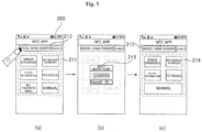
- FIG. 5 is a view showing the construction of a control menu changed according to a model name
- FIG. 6 is a view showing the construction of a control menu according to the type of an air conditioner.
- At least one control menu 211 and an object to be controlled i.e. a model information window 212, are displayed.
- Error diagnosis, refrigerant diagnosis, filter information, schedule, my favorite wind, and manual items are displayed as the control menu 211.
- a popup window 213 to input a model name is displayed on a screen as shown in FIG. 5(b) .
- the input model name is displayed on the screen and a changed control menu 214 based on the model name is displayed on the screen as shown in FIG. 5(c) .
- Error diagnosis, refrigerant diagnosis, filter information, schedule, and manual items may be displayed as the changed control menu 214.
- the control menu is changed and displayed based on the input model name.
- the terminal controller 210 determines the model type of the air conditioner based on the input model name and classifies functions that can be supported per model type to change the construction of the control menu.
- An indoor unit type selection menu is configured to select any one from between a stand type 215 and a wall mount type 216.
- the air conditioner is configured based on various indoor unit types, such as a ceiling type, an indoor and outdoor unit combination type, a stand type, and a wall mount type. At home, the stand type and the wall mount type are generally used. For this reason, any one is selected from between the stand type and the wall mount type.
- the model name may be input to classify the type of the air conditioner as previously described with reference to FIG. 5 .
- a control menu 217 corresponding to the stand type is displayed on the screen as shown in FIG. 6(b) .
- a control menu 218 corresponding to the wall mount type is displayed on the screen as shown in FIG. 6(c) .
- error diagnosis, refrigerant diagnosis, filter information, schedule, my favorite wind, and manual functions are provided.
- error diagnosis, refrigerant diagnosis, filter information, schedule, and manual functions are provided.
- the terminal 20 Since settable or changeable functions are changed based on the type of the air conditioner and the indoor unit type as described above, the terminal 20 differently displays the control menu based on the input model name or indoor unit type.
- FIGS. 7 to 12 are reference views illustrating a method of a terminal setting a home appliance according to an embodiment of the present invention.
- FIG. 7 is a reference view illustrating a method of a terminal diagnosing an error of an air conditioner.
- a control menu 221 including settable functions is displayed on the display unit 260 of the terminal as shown in FIG. 7(a) . Error diagnosis, refrigerant diagnosis, filter information, schedule, and my favorite wind items are displayed as the control menu.
- An error diagnosis item 222 is selected and then the terminal 20 is brought into contact with the tag unit 140 of the indoor unit of the air conditioner 10. At this time, communication between the terminal 20 and the tag unit 140 is performed when the terminal approaches tag unit 140 within a predetermined distance as well as contact between the terminal 20 and the tag unit 140. At this time, a tagging method of the terminal or a guide message indicating how the terminal tags the indoor unit may be displayed on the screen of the display unit. The guide message may be displayed as text or an image. At the same time, a voice may be output.
- the tag communication module 241 of the terminal communicates with the tag unit 140 of the indoor unit such that the tag communication module 241 of the terminal and the tag unit 140 of the indoor unit transmit and receive data to and from each other.
- the terminal controller of the terminal 20 requests data necessary for error diagnosis through the tag communication module 241.
- the transmission and reception unit 142 of the tag unit 140 reads data of the air conditioner stored in the tag storage unit 141 and transmits the read data to the terminal according to the request of the terminal. At this time, in a case in which the requested data are not present in the tag storage unit 141, the transmission and reception unit 142 may request data from the controller 110 and transmit received data to the terminal 20.
- Data necessary for error diagnosis include error codes generated during recent operation of the air conditioner.
- the data necessary for error diagnosis may include operation settings when an error of the air conditioner has occurred and data, such as temperature values including intake temperature, discharge temperature, and refrigerant temperature, refrigerant pressure values including high pressure and low pressure, and valve opening and closing control, sensed or measured during operation of the air conditioner.
- the data necessary for error diagnosis may include data regarding when the error of the air conditioner has occurred and data regarding the number of times of error occurrence.
- a predetermined guide message indicating that it is necessary to maintain contact between the terminal 20 and the tag unit 140 may be displayed.
- a guide message indicating that the communication between the terminal 20 and the tag unit 140 has been completed may be displayed.
- a predetermined effect sound indicating that the communication between the terminal 20 and the tag unit 140 has been completed may be output through the speaker 230.
- the terminal controller 210 analyzes the data received through the tag communication module 241 to diagnose an error of the air conditioner.
- the terminal controller 210 analyzes a failure type of the air conditioner based on an error code and derives the result of diagnosis.
- the terminal controller 210 may analyze other data including error codes and receive external data to perform error diagnosis.
- a progress state of analysis and diagnosis of data or a guide message indicating that analysis and diagnosis of data are being performed is output to the screen of the display unit 260 as shown in FIG. 7(c) .
- the terminal controller 210 stops the error diagnosis and displays the control menu.
- the terminal controller 210 When analysis and diagnosis is completed, the terminal controller 210 outputs the result of diagnosis to the screen of the display unit 260 as shown in FIG. 7 (d) . At this time, the result of diagnosis is output to the screen as brief information.
- a selection key 223 to select any one from between the indoor unit and the outdoor unit is displayed on the screen.
- the terminal controller 210 displays detailed information of one selected from between the indoor unit and the outdoor unit, e.g. the indoor unit or the outdoor unit.
- the control menu 221 shown in FIG. 7(a) is displayed.
- FIG. 8 is a reference view illustrating a method of the terminal diagnosing a refrigerant of the air conditioner.
- a control menu 221 based on the model name or the indoor unit type is displayed on the screen.
- a refrigerant diagnosis item 224 is selected and then the terminal 20 is brought into contact with the tag unit 140 of the indoor unit of the air conditioner 10 as shown in FIG. 8(b) .
- a tagging method of the terminal or a guide message indicating how the terminal tags the indoor unit may be displayed on the screen of the display unit.
- communication between the terminal 20 and the tag unit 140 may be performed when the terminal approaches tag unit 140 within a predetermined distance as well as contact between the terminal 20 and the tag unit 140.
- a predetermined guide message indicating that it is necessary to maintain contact between the terminal 20 and the tag unit 140 may be displayed.
- a guide message indicating that the communication between the terminal 20 and the tag unit 140 has been completed may be displayed.
- a predetermined effect sound indicating that the communication between the terminal 20 and the tag unit 140 has been completed may be output through the speaker 230.
- the guide message may be displayed as text or an image. At the same time, a voice may be output.
- the terminal controller 210 communicates with the tag unit 140 of the indoor unit of the air conditioner 10 through the tag communication module 241 to receive data necessary for refrigerant diagnosis.
- the transmission and reception unit 142 of the tag unit 140 transmits data stored in the tag storage unit 141 to the terminal according to the request of the terminal.
- Data necessary for refrigerant diagnosis may include flow rate of the refrigerant, pressure of the refrigerant, and temperature change data during operation.
- the terminal controller 210 analyzes the data received through the tag communication module 241 to diagnose the amount of the refrigerant. At this time, a guide message indicating that analysis is being performed is output as shown in FIG. 8(c) .
- the terminal controller 210 When refrigerant diagnosis is completed, the terminal controller 210 outputs the result of refrigerant diagnosis to the screen as shown in FIG. 8(d) .
- a guide message indicating that it is necessary to replenish the refrigerant is output. According to circumstances, a guide message indicating a refrigerant replenishment method and a service center contact method may be further output.
- FIG. 9 is a reference view illustrating a method of the terminal checking filter information of the air conditioner. As shown in FIG. 9(a) , a control menu 221 based on the model name or the indoor unit type is displayed on the screen.
- a model name input window is displayed as shown in FIG. 9(b) .
- the model name is input and then the terminal 20 is brought into contact with the tag unit 140 of the indoor unit of the air conditioner 10 as shown in FIG. 9(c) .
- Communication between the terminal 20 and the tag unit 140of the indoor unit based on contact between the terminal 20 and the tag unit 140of the indoor unit is performed as previously described.
- the terminal controller 210 communicates with the tag unit 140 of the indoor unit of the air conditioner 10 through the tag communication module 241 to request product information and filter information based on the model name.
- the transmission and reception unit 142 of the tag unit 140 transmits product information and filter information stored in the tag storage unit 141 to the terminal according to the request of the terminal.
- the terminal controller 210 compares the product information and the filter information received through the tag communication module 241 to display filter type corresponding to the produce and information regarding properties of each filter on the screen as shown in FIG. 9(d) . At this time, information regarding filter types that can be applied to the indoor unit, features of the filters, a filter replacement cycle, and whether the filters can be washed or not is provided.
- the terminal controller 210 may receive information regarding the type of the filter mounted in the indoor unit and when the filter has been finally replaced, compare the received information with the above-described filter information to determine when the filter will be replaced based on the filter type and to display whether or not it is necessary to replace the filter.
- FIG. 10 is a reference view illustrating a method of the terminal setting an operation schedule of the air conditioner. As shown in FIG. 10(a) , a control menu 221 based on the model name or the indoor unit type is displayed on the screen.
- a schedule setting menu 229 is displayed on the screen as shown in FIG. 10(b) .
- a tropical night sleeping schedule, a power on schedule, and a power off schedule may be set through the schedule setting menu 229. Hours and minutes may be set to set operation time, such as power off after two hours or power off after one hour. In addition, settings may be configured such that the air conditioner is powered on or powered off at a predetermined time. Time when the air conditioner is powered on may be set such that the air conditioner is operated at a predetermined time.
- a guide message indicating that the communication between the terminal 20 and the tag unit 140 is being performed may be displayed as previously described.
- a guide message indicating that it is necessary to maintain contact between the terminal 20 and the tag unit 140 for a predetermined time may be displayed.
- the terminal controller 210 transmits the schedule information set through the schedule setting menu 229 to the tag unit 140of the indoor unit through the tag communication module 241.
- the transmission and reception unit 142 of the tag unit 140 receives the schedule information from the terminal and stores the received schedule information in the tag storage unit 141.
- a setting indicating that new data have been stored in the tag storage unit 141 is performed.
- the controller 110 When communication with the terminal 20 is completed during operation of the indoor unit, the controller 110 receives the schedule information stored in the tag storage unit 141, sets an operation schedule, and stores the set operation schedule in the data unit.
- the schedule information When the schedule information is received from the terminal 20 in a state in which the operation of the indoor unit is stopped, on the other hand, the schedule information remains stored in the tag storage unit 141.
- the terminal controller 110 checks that new data have been stored in the tag storage unit 141 and receives the schedule information stored in the tag storage unit 141 to set an operation schedule.
- the air conditioner may be powered off at a designated time or may be powered on at a designated time and then operated according to the set operation schedule.
- FIG. 11 is a reference view illustrating a method of the terminal setting operation of the air conditioner per user. As shown in FIG. 11(a) , a control menu 221 based on the model name or the indoor unit type is displayed on the screen.
- a user setting menu 232 is displayed on the screen as shown in FIG. 11(b) .
- a name of the user setting menu may be input through the user setting menu 232.
- One operation mode selected from among cooling, dehumidification, heating, and purification may be set through the user setting menu 232.
- desired temperature related to the cooling or the heating may be set through the user setting menu 232.
- Wind intensity may be set to one selected from low, intermediate, high, and power.
- wind directions such as super cool power, long power, and forest wind, may be set.
- the user setting menu may be changed based on the type of the air conditioner and the selected mode of the air conditioner. For example, in the dehumidification or purification mode, the setting of the desired temperature is disabled and thus cannot be selected.
- the input user setting is further registered with a 'my favorite wind' menu 233 as shown in FIG. 11(c) .
- a plurality of user setting values are registered as unique names with the 'my favorite wind' menu 233 and displayed.
- Predetermined user settings such as mountain wind, kitchen wind, baby wind, and front door wind, are displayed as designated icons.
- brief information which has been recently added is displayed on the upper end of the screen.
- the user setting menu 232 is displayed as previously described with reference to FIG. 11(b) .
- An operation mode, temperature, air volume, and wind direction may be set and further registered as a new 'may wish' menu.
- the terminal 20 When an enter key is selected or a tag sending key is selected, the terminal 20 is brought into contact with the tag unit 140 of the indoor unit of the air conditioner 10 as shown in FIG. 11(d) .
- a cancel key is selected, the control menu 221 or the 'my favorite wind' menu 233 is displayed.
- a guide message indicating that the communication between the terminal 20 and the tag unit 140 is being performed may be displayed as previously described.
- a guide message indicating that it is necessary to maintain contact between the terminal 20 and the tag unit 140 for a predetermined time may be displayed.
- the terminal controller 210 transmits the 'my favorite wind' setting selected from among the newly registered or pre-stored settings to the tag unit 140of the indoor unit of the air conditioner 10 through the tag communication module 241.
- the transmission and reception unit 142 of the tag unit 140 receives the setting information regarding my favorite wind from the terminal 20 and stores the received setting information in the tag storage unit 141. A setting indicating that new data have been stored in the tag storage unit 141 is performed.
- the controller 110 receives the setting information regarding my favorite wind stored in the tag storage unit 141 and stores the received setting information regarding my favorite wind in the data unit. In addition, as shown in FIG. 11(3) , the controller 110 changes the operation settings and controls the drive control unit such that the air conditioner is operated according to the setting information regarding my favorite wind.
- the terminal controller 110 checks that new data have been stored in the tag storage unit 141 and receives the setting information regarding my favorite wind stored in the tag storage unit 141 to set an operation schedule.
- the indoor unit is powered off at a designated time or is powered on at a designated time and then operated according to the set operation schedule.
- FIG. 12 is a reference view illustrating a method of the terminal checking operation information of the air conditioner. As shown in FIG. 12(a) , a control menu 235 based on the model name or the indoor unit type is displayed on the screen.
- An operation information item 236 is selected and then the terminal 20 is brought into contact with the tag unit 140 of the indoor unit of the air conditioner 10 as shown in FIG. 12(b) . Communication between the terminal 20 and the tag unit 140of the indoor unit based on contact between the terminal 20 and the tag unit 140of the indoor unit is performed as previously described.
- the terminal controller 210 communicates with the tag unit 140 of the indoor unit of the air conditioner 10 through the tag communication module 241 to request operation information of the air conditioner which is currently being operated.
- the transmission and reception unit 142 of the tag unit 140 transmits operation information stored in the tag storage unit 141 to the terminal according to the request of the terminal.
- the terminal controller 210 Upon receiving the operation information through the tag communication module 241, the terminal controller 210 analyzes the operation information and outputs a guide message indicating that the information is being checked as shown in FIG. 12(c) .
- the terminal controller 210 displays the operation information received through the tag unit 140 on the screen as shown in FIG. 12(d) .
- the terminal controller 210 displays the currently set operation mode on the upper end of the screen and displays temperature information 237 including desired temperature and room temperature. In addition, the terminal controller 210 displays a 'my favorite wind' icon 238 and an air stream icon 239 on a portion of the screen.
- the home appliance may be controlled using the remote controller, receive data through the terminal, and simply perform operation settings and schedule settings.
- the user may receive an operation state of the home appliance though one contact between the home appliance and the terminal to check the operation state of the home appliance through the terminal and control operation of the home appliance based on settings input through the terminal.
- the home appliance system, and the control method thereof according to the present invention it is possible to perform transmission and reception of data between the terminal and the home appliance using the near field communication (NFC), thereby easily checking various kinds of information of the home appliance.
- NFC near field communication
Landscapes
- Engineering & Computer Science (AREA)
- General Engineering & Computer Science (AREA)
- Chemical & Material Sciences (AREA)
- Combustion & Propulsion (AREA)
- Mechanical Engineering (AREA)
- Physics & Mathematics (AREA)
- Signal Processing (AREA)
- Human Computer Interaction (AREA)
- General Physics & Mathematics (AREA)
- Mathematical Physics (AREA)
- Fuzzy Systems (AREA)
- Theoretical Computer Science (AREA)
- Automation & Control Theory (AREA)
- Health & Medical Sciences (AREA)
- Biomedical Technology (AREA)
- Fluid Mechanics (AREA)
- Computer Networks & Wireless Communication (AREA)
- Manufacturing & Machinery (AREA)
- Quality & Reliability (AREA)
- Selective Calling Equipment (AREA)
- Air Conditioning Control Device (AREA)
Claims (14)
- Système d'appareil ménager, comprenant :un terminal (20) présentant une fonction de communication en champ proche ; etun appareil ménager (10) comprenant une unité d'étiquette (140) pour effectuer la communication en champ proche, l'appareil ménager étant prévu : pour stocker des données de l'appareil ménager dans l'unité d'étiquette (140) ; pour transmettre les données stockées de l'appareil ménager au terminal (20) ; et pour commander le fonctionnement de l'appareil ménager en réponse aux données reçues par l'unité d'étiquette (140),où l'unité d'étiquette (140) comprend :une unité de stockage d'étiquette (141) prévue pour stocker des données ; etune unité de transmission et de réception (142) prévue pour reconnaître le terminal (20) se rapprochant de l'appareil ménager (10) dans un rayon défini ou contactant l'appareil ménager par communication en champ proche, et pour transmettre des données au terminal et en recevoir de celui-ci,où l'appareil ménager comprend : un contrôleur (110) prévu : pour recevoir les données stockées dans l'unité de stockage d'étiquette (141) afin de changer les paramètres fonctionnels de l'appareil ménager (10) et commander le fonctionnement de l'appareil ménager ; et pour stocker des données correspondant à une demande du terminal (20) reçue par l'unité de transmission et de réception (142) dans l'unité de stockage d'étiquette (141), de telle manière que les données sont transmises au terminal (20) par l'unité de transmission et de réception (142),où le terminal (20) est prévu pour exécuter une application destinée à commander l'appareil ménager pour qu'il transmette à l'unité d'étiquette (140) des données et en reçoive de celle-ci par communication en champ proche,ledit système d'appareil ménager étant caractérisé en ce quele terminal (20) est prévu pour configurer différemment un menu de commande (211) de l'application sur la base d'un modèle ou d'un type de l'appareil ménager (10), de manière à commander et à surveiller l'appareil ménager.
- Système d'appareil ménager selon la revendication 1, où le contrôleur (110) est prévu pour stocker au moins un des éléments suivants : des informations de fonctionnement, l'état de fonctionnement, des données d'erreur, des données de réfrigérant, et des informations de produit sur l'appareil ménager dans l'unité de stockage d'étiquette (141) en réponse à la demande du terminal (20) reçue par l'unité d'étiquette (140).
- Système d'appareil ménager selon la revendication 1 ou la revendication 2, où le contrôleur (110) est prévu pour commuter le fonctionnement de l'appareil ménager en réponse à des informations de programmation ou des informations de paramétrage fonctionnel stockées dans l'unité de stockage d'étiquette (141), et pour stocker les informations de fonctionnement et l'état de fonctionnement de l'appareil ménager dans l'unité de stockage d'étiquette (141) en réponse à la commutation de fonctionnement de l'appareil ménager.
- Système d'appareil ménager selon l'une des revendications précédentes, où le terminal (20) comprend :une unité d'affichage (260) prévue pour sortir des informations de fonctionnement de l'appareil ménager ;une unité de communication d'étiquette (241) prévue pour transmettre des données à l'appareil ménager et en recevoir de celui-ci par communication en champ proche ; etun contrôleur (210) de terminal prévu : pour transmettre une entrée de données de paramétrage par l'unité de communication d'étiquette (241) à l'appareil ménager (10) pourvu de l'unité d'étiquette (140) pour communication en champ proche ; pour analyser des données reçues de l'appareil ménager ; pour sortir les données analysées par l'unité d'affichage (260) ; et pour transmettre des données à l'appareil ménager (10) et en recevoir de celui-ci par l'unité de communication d'étiquette (241) afin de commander l'appareil ménager.
- Système d'appareil ménager selon la revendication 4, où le contrôleur (210) de terminal est prévu pour configurer le menu de commande (211) de telle manière que le menu de commande comprend au moins une des fonctions suivantes : diagnostic d'erreur, diagnostic de réfrigérant, informations de filtre, programmation, débit d'air favori, manuel et informations de fonctionnement.
- Système d'appareil ménager selon la revendication 5, où le contrôleur (210) de terminal est prévu pour demander des données de l'appareil ménager (10) par l'unité de communication d'étiquette (241) si une fonction est sélectionnée entre : diagnostic d'erreur, diagnostic de réfrigérant, informations de filtre et informations de fonctionnement via le menu de commande (211), et
pour analyser les données reçues de l'appareil ménager (10) par l'unité de communication d'étiquette (241) afin d'exécuter le diagnostic d'erreur ou le diagnostic de réfrigérant pour l'appareil ménager et pour afficher le résultat de diagnostic sur l'écran de l'unité d'affichage (260). - Système d'appareil ménager selon la revendication 6, où
le contrôleur (210) de terminal est prévu : pour analyser les données reçues de l'appareil ménager (10) par l'unité de communication d'étiquette (241) ; et pour afficher les informations d'un filtre monté dans l'appareil ménager (10) sur l'écran de l'unité d'affichage (260), et/ou afficher des informations relatives à l'intervalle de remplacement du filtre monté dans l'appareil ménager (10) sur l'écran de l'unité d'affichage (260), sur la base d'un type ou d'un temps de montage du filtre. - Système d'appareil ménager selon l'une des revendications 5 à 7, où,
si une fonction est sélectionnée entre : programmation, débit d'air favori et manuel par le menu de commande (211), le contrôleur (210) de terminal est prévu pour afficher sur l'écran de l'unité d'affichage (260) un menu de paramétrage correspondant à la fonction sélectionnée, et
pour transmettre une entrée de données de paramétrage par le menu de paramétrage à l'appareil ménager (10) via l'unité de communication d'étiquette (241). - Système d'appareil ménager selon la revendication 8, où,
si la fonction débit d'air favori (231) est sélectionnée, le contrôleur (210) de terminal est prévu pour afficher un menu de paramétrage d'utilisateur (232) en tant que menu de paramétrage pour enregistrer additionnellement un nouveau paramétrage de la fonction débit d'air favori, et
pour transmettre à l'appareil ménager (10) des données de paramétrage sélectionnées parmi des paramétrages enregistrés de la fonction débit d'air favori. - Système d'appareil ménager selon la revendication 1, où l'appareil ménager (10) comprend en outre une unité d'affichage (160) prévue pour afficher des informations de fonctionnement et un état de fonctionnement de l'appareil ménager.
- Procédé de fonctionnement d'un système d'appareil ménager pour la commande d'un appareil ménager (10), comprenant :l'exécution via un terminal (20) d'une application pour commander l'appareil ménager (10) ;la configuration différenciée via le terminal (20) d'un menu de commande (211) sur la base d'un modèle ou d'un type de l'appareil ménager, et l'affichage du menu de commande sur l'écran d'une unité d'affichage (260) ;l'affichage via le terminal (20) d'un menu de paramétrage pour commander l'appareil ménager (10) sur la base de l'item sélectionné dans le menu de commande (221) ;la transmission à l'appareil ménager (10) par communication en champ proche (NFC), via le terminal (20), d'une entrée de données de paramétrage par le menu de paramétrage ;la demande via le terminal (20) de données de l'appareil ménager (10) par communication en champ proche (NFC) sur la base d'un item sélectionné dans le menu de commande (211) ;le stockage via un appareil ménager (10) de données dans une unité d'étiquette (140) en réponse à la demande ; etl'analyse, via le terminal (20), de données reçues de l'unité d'étiquette (140) de l'appareil ménager (10) et l'affichage d'informations relatives à l'appareil ménager (10),où l'unité d'étiquette (140) et le terminal (20) transmettent et reçoivent des données par un contact entre l'unité d'étiquette (140) et le terminal (20).
- Procédé selon la revendication 11, comprenant en outre la demande de données de l'appareil ménager (10) par communication en champ proche si une fonction est sélectionnée entre : diagnostic d'erreur, diagnostic de réfrigérant, informations de filtre et informations de fonctionnement via le menu de commande (221).
- Procédé selon la revendication 11 ou la revendication 12, comprenant en outre :l'analyse des données reçues de l'appareil ménager (10) pour exécuter le diagnostic d'erreur ou le diagnostic de réfrigérant pour l'appareil ménager, et l'affichage du résultat du diagnostic sur l'écran de l'unité d'affichage (260) ; et/oul'analyse des données reçues de l'appareil ménager (10) et, sur cette base, l'affichage d'informations d'un filtre monté dans l'appareil ménager sur l'écran de l'unité d'affichage (260) et/ou l'affichage d'informations relatives à l'intervalle de remplacement du filtre monté dans l'appareil ménager sur la base d'un type ou d'un temps de montage du filtre sur l'écran de l'unité d'affichage (260).
- Procédé selon la revendication 11 à 13, comprenant en outre, si une fonction est sélectionnée entre : programmation, débit d'air favori et manuel par le menu de commande (211), l'affichage du menu de paramétrage correspondant à la fonction sélectionnée sur l'écran de l'unité d'affichage (260), et
préférentiellement, si la fonction débit d'air favori (231) est sélectionnée, l'affichage d'un menu de paramétrage d'utilisateur (232) en tant que menu de paramétrage pour enregistrer additionnellement un nouveau paramétrage de la fonction débit d'air favori et transmettre à l'appareil ménager (10) des données de paramétrage sélectionnées parmi des paramétrages enregistrés de la fonction débit d'air favori.
Applications Claiming Priority (1)
| Application Number | Priority Date | Filing Date | Title |
|---|---|---|---|
| KR1020130099860A KR102122266B1 (ko) | 2013-08-22 | 2013-08-22 | 가전기기, 가전기기 시스템 및 그 제어방법 |
Publications (2)
| Publication Number | Publication Date |
|---|---|
| EP2846105A1 EP2846105A1 (fr) | 2015-03-11 |
| EP2846105B1 true EP2846105B1 (fr) | 2019-08-07 |
Family
ID=51390011
Family Applications (1)
| Application Number | Title | Priority Date | Filing Date |
|---|---|---|---|
| EP14181799.9A Active EP2846105B1 (fr) | 2013-08-22 | 2014-08-21 | Appareil domestique, systeme d'appareil domestique, méthode de commande de celui-ci |
Country Status (4)
| Country | Link |
|---|---|
| US (1) | US9760065B2 (fr) |
| EP (1) | EP2846105B1 (fr) |
| KR (1) | KR102122266B1 (fr) |
| CN (1) | CN104423301B (fr) |
Families Citing this family (27)
| Publication number | Priority date | Publication date | Assignee | Title |
|---|---|---|---|---|
| US9273878B2 (en) * | 2013-05-22 | 2016-03-01 | Honeywell International Inc. | Device interface for a building appliance |
| JP5804018B2 (ja) * | 2013-10-10 | 2015-11-04 | ダイキン工業株式会社 | 空気調和機 |
| US9494333B2 (en) * | 2013-11-08 | 2016-11-15 | Emerson Electric Co. | Driving controls and diagnostic methods for communicating motors |
| US10291292B2 (en) | 2014-09-02 | 2019-05-14 | Johnson Controls Technology Company | Wireless sensor with near field communication circuit |
| US9732977B2 (en) | 2014-09-02 | 2017-08-15 | Johnson Controls Technology Company | Systems and methods for configuring and communicating with HVAC devices |
| JP6459728B2 (ja) | 2015-04-01 | 2019-01-30 | ダイキン工業株式会社 | 空気調和機用のリモコン装置及びこれを備えた空気調和機 |
| CN105101083A (zh) * | 2015-07-15 | 2015-11-25 | 魅族科技(中国)有限公司 | 室内电子设备的控制方法及装置 |
| CN105157175B (zh) * | 2015-09-07 | 2018-10-23 | 珠海格力电器股份有限公司 | 空调显示器数据交互方法 |
| KR101754684B1 (ko) * | 2015-09-11 | 2017-07-19 | 엘지전자 주식회사 | 이동 단말기, 및 전자 기기 |
| JP6256445B2 (ja) * | 2015-09-30 | 2018-01-10 | ダイキン工業株式会社 | Icカートリッジ及環境調整装置 |
| CN105319973B (zh) * | 2015-10-14 | 2018-05-04 | 深圳市二八智能家居有限公司 | 一种通过扫描二维码更换智能家居设备的方法及装置 |
| CN107797890A (zh) * | 2016-09-05 | 2018-03-13 | 英业达科技有限公司 | 除错系统与除错电子装置 |
| US10887125B2 (en) * | 2017-09-15 | 2021-01-05 | Kohler Co. | Bathroom speaker |
| CN108800454B (zh) * | 2018-04-13 | 2020-11-10 | 珠海格力电器股份有限公司 | 数据同步方法及装置、多联机空调系统 |
| JP7284636B2 (ja) * | 2019-05-24 | 2023-05-31 | シャープ株式会社 | 家電機器及び家電機器システム |
| CN112449329A (zh) * | 2019-08-30 | 2021-03-05 | 广东美的制冷设备有限公司 | 信息传输方法、发送终端、接收终端及电子设备 |
| CN111076315A (zh) * | 2019-11-28 | 2020-04-28 | 杭州格米环境科技有限公司 | 一种无线操作除湿机 |
| CN111399392B (zh) * | 2020-04-02 | 2022-02-01 | 深圳创维-Rgb电子有限公司 | 基于智慧屏的智能家居交互控制方法、装置和智慧屏 |
| CN112019633B (zh) * | 2020-09-03 | 2021-03-23 | 景亮 | 一种城市轨道交通信息化控制系统及其运行方法 |
| KR102505288B1 (ko) * | 2020-10-28 | 2023-03-02 | 주식회사 에이펄스테크롤리지 | 스위치 기능을 갖는 rfid 태그 모듈 |
| CN112378042B (zh) * | 2020-11-12 | 2022-04-08 | 海信(山东)空调有限公司 | 空调器运行参数设定方法及空调器 |
| CN112628961B (zh) * | 2020-12-04 | 2022-02-22 | 珠海格力电器股份有限公司 | 一种调温器控制变频空调的调频方式 |
| JP7472804B2 (ja) * | 2021-01-22 | 2024-04-23 | トヨタ自動車株式会社 | 情報処理方法、情報処理システム、情報処理装置、およびプログラム |
| CN116068905A (zh) * | 2021-11-01 | 2023-05-05 | 芜湖美的厨卫电器制造有限公司 | 智能家电的控制方法及系统、电子设备及计算机存储介质 |
| CN115685835A (zh) * | 2022-10-31 | 2023-02-03 | 青岛海信日立空调系统有限公司 | 一种家电设备的控制方法及家电设备 |
| CN118694903A (zh) * | 2023-03-21 | 2024-09-24 | 中强光电股份有限公司 | 投影系统及投影系统的操作方法 |
| CN116465066A (zh) * | 2023-04-12 | 2023-07-21 | 安庆三维电器有限公司 | 一种冷暖风机控制系统 |
Family Cites Families (46)
| Publication number | Priority date | Publication date | Assignee | Title |
|---|---|---|---|---|
| US20040261626A1 (en) * | 2002-03-26 | 2004-12-30 | Tmio, Llc | Home appliances provided with control systems which may be actuated from a remote location |
| JP4149178B2 (ja) * | 2001-03-09 | 2008-09-10 | 松下電器産業株式会社 | リモートメンテナンスシステム |
| US8060010B2 (en) * | 2003-10-29 | 2011-11-15 | Nxp B.V. | Communication partner appliance with automatic send mode activation |
| JP4455170B2 (ja) * | 2004-05-31 | 2010-04-21 | 株式会社東芝 | ネットワーク家電制御システム |
| JP4777725B2 (ja) | 2005-08-31 | 2011-09-21 | フェリカネットワークス株式会社 | 携帯端末装置,サーバ装置,アプリケーション提供方法およびコンピュータプログラム |
| US8548334B2 (en) * | 2006-12-06 | 2013-10-01 | Mohammad Mazed | Dynamic intelligent bidirectional optical access communication system with object/intelligent appliance-to-object/intelligent appliance interaction |
| US8010321B2 (en) * | 2007-05-04 | 2011-08-30 | Applied Materials, Inc. | Metrics independent and recipe independent fault classes |
| US20090106160A1 (en) * | 2007-10-19 | 2009-04-23 | First Data Corporation | Authorizations for mobile contactless payment transactions |
| US8051381B2 (en) * | 2008-12-22 | 2011-11-01 | Whirlpool Corporation | Appliance with a graphical user interface for configuring an accessory |
| JP4910035B2 (ja) | 2009-11-13 | 2012-04-04 | 株式会社東芝 | 電子機器および通信制御方法 |
| US9020432B2 (en) * | 2009-11-30 | 2015-04-28 | Panasonic Intellectual Property Corporation Of America | Mobile communication device, communication method, integrated circuit, and program |
| WO2012011289A1 (fr) * | 2010-07-23 | 2012-01-26 | パナソニック株式会社 | Appareil de communication nfc et procédé de commande associé |
| JP5886205B2 (ja) * | 2010-11-25 | 2016-03-16 | パナソニック インテレクチュアル プロパティ コーポレーション オブアメリカPanasonic Intellectual Property Corporation of America | 通信機器 |
| US9071955B2 (en) * | 2010-11-30 | 2015-06-30 | Panasonic Intellectual Property Corporation Of America | Communication device and communication method |
| KR20120065659A (ko) * | 2010-12-13 | 2012-06-21 | 엘지전자 주식회사 | 공기조화장치 및 공기조화장치의 제어방법 |
| KR101191593B1 (ko) | 2010-12-13 | 2012-10-15 | 성열규 | 집진기능을 가지는 방충망 |
| KR101737123B1 (ko) * | 2011-01-12 | 2017-05-17 | 엘지전자 주식회사 | 네트워트 장치의 제어방법 |
| US8831981B2 (en) * | 2011-01-18 | 2014-09-09 | Proximiant, Inc. | Electronic transaction record distribution system |
| US20120185306A1 (en) * | 2011-01-18 | 2012-07-19 | Fang Cheng | Electronic Transaction Record Distribution System |
| US20130285837A1 (en) * | 2011-01-19 | 2013-10-31 | Nec Casio Mobile Communications, Ltd. | Mobile communication device and communication method |
| KR101764251B1 (ko) * | 2011-04-19 | 2017-08-04 | 삼성전자주식회사 | 전력 사용 상태 표시 방법 및 이를 적용한 휴대기기 |
| US8879985B2 (en) * | 2011-06-28 | 2014-11-04 | Broadcom Corporation | Memory arbitrator for electronics communications devices |
| US9326114B2 (en) * | 2011-07-14 | 2016-04-26 | Blackberry Limited | Transferring a voice call |
| US8461725B1 (en) * | 2011-08-09 | 2013-06-11 | Google Inc. | Identification of powered devices for energy saving |
| US20130052946A1 (en) * | 2011-08-23 | 2013-02-28 | Manjirnath Chatterjee | Home automation using a mobile device |
| WO2013035242A1 (fr) * | 2011-09-09 | 2013-03-14 | パナソニック株式会社 | Système de buanderie, dispositif de communication, procédé de communication, programme de communication et machine à laver |
| JP5185471B1 (ja) * | 2011-09-09 | 2013-04-17 | パナソニック株式会社 | 通信システム、通信装置、通信方法、通信プログラム及び電気機器 |
| KR101940073B1 (ko) * | 2011-09-20 | 2019-01-18 | 엘지전자 주식회사 | 네트워크 시스템 및 그 제어방법 |
| US9992645B2 (en) * | 2011-09-23 | 2018-06-05 | Genesys Telecommunications Laboratories, Inc. | Universal connection station |
| DE102011055738B4 (de) * | 2011-11-25 | 2021-10-21 | Infineon Technologies Ag | Kommunikationsverfahren zwischen elektronischen Geräten und entsprechende Geräte |
| KR101844211B1 (ko) * | 2011-12-28 | 2018-05-15 | 삼성전자주식회사 | 가전기기의 네트워크 시스템 및 그 네트워크 설정 방법 |
| US10373161B2 (en) * | 2011-12-30 | 2019-08-06 | Paypal, Inc. | Offline mobile phone payments |
| US20130173076A1 (en) * | 2012-01-02 | 2013-07-04 | Yang Pan | Power Management System and Method Using Power Limiter |
| US20130198056A1 (en) * | 2012-01-27 | 2013-08-01 | Verizon Patent And Licensing Inc. | Near field communication transaction management and application systems and methods |
| US8880028B2 (en) * | 2012-02-08 | 2014-11-04 | Blackberry Limited | Near field communication (NFC) accessory providing enhanced data transfer features and related methods |
| US10455017B2 (en) * | 2012-02-28 | 2019-10-22 | Panasonic Intellectual Property Management Co., Ltd. | Communication system, electric appliance, and portable terminal device |
| DE102012102382B4 (de) * | 2012-03-21 | 2019-05-02 | Infineon Technologies Ag | Steuerungsverfahren für eine Kommunikation zwischen elektronischen Geräten und entsprechende Geräte |
| DE102012102381A1 (de) * | 2012-03-21 | 2013-09-26 | Infineon Technologies Ag | Steuerungsverfahren mit gezielter Stummschaltung für eine Kommunikation zwischen elektronischen Geräten, und entsprechende Geräte |
| DE102012102383A1 (de) * | 2012-03-21 | 2013-09-26 | Infineon Technologies Ag | Steuerungsverfahren mittels Weiterleitung für eine Kommunikation zwischen elektronischen Geräten, und entsprechende Geräte |
| EP2648057B1 (fr) * | 2012-04-07 | 2021-10-13 | Samsung Electronics Co., Ltd. | Utilisation d'un terminal mobile pour fournir des informations de contrôle à un appareil électronique grand public concernant un produit |
| CN102768514A (zh) | 2012-07-06 | 2012-11-07 | 南京物联传感技术有限公司 | 一种家居控制系统及其控制方法 |
| US9084114B2 (en) * | 2012-08-07 | 2015-07-14 | Genesys Telecommunications Laboratories, Inc. | Technique to authenticate in a mobile application using near-field communication |
| US10083548B2 (en) * | 2012-09-07 | 2018-09-25 | Cellco Partnership | Appliance diagnostic information via a wireless communication link |
| US9165233B2 (en) * | 2012-11-09 | 2015-10-20 | Cellotape, Inc. | Method, system and apparatus for automatically linking digital content to a device |
| US9128931B2 (en) * | 2012-12-17 | 2015-09-08 | General Electric Company | Communication of digital information presented on an appliance display |
| US9942515B2 (en) * | 2013-03-14 | 2018-04-10 | Microsoft Technology Licensing, Llc | Smart device pairing and configuration for meeting spaces |
-
2013
- 2013-08-22 KR KR1020130099860A patent/KR102122266B1/ko active Active
-
2014
- 2014-08-21 EP EP14181799.9A patent/EP2846105B1/fr active Active
- 2014-08-22 CN CN201410419593.5A patent/CN104423301B/zh active Active
- 2014-08-22 US US14/466,017 patent/US9760065B2/en active Active
Non-Patent Citations (1)
| Title |
|---|
| None * |
Also Published As
| Publication number | Publication date |
|---|---|
| CN104423301A (zh) | 2015-03-18 |
| CN104423301B (zh) | 2018-03-09 |
| KR20150022255A (ko) | 2015-03-04 |
| EP2846105A1 (fr) | 2015-03-11 |
| KR102122266B1 (ko) | 2020-06-26 |
| US20150081103A1 (en) | 2015-03-19 |
| US9760065B2 (en) | 2017-09-12 |
Similar Documents
| Publication | Publication Date | Title |
|---|---|---|
| EP2846105B1 (fr) | Appareil domestique, systeme d'appareil domestique, méthode de commande de celui-ci | |
| US10769735B2 (en) | Thermostat with user interface features | |
| KR101517084B1 (ko) | 공기조화기용 제어장치 | |
| US20180231995A1 (en) | Method and system for configuring wireles sensors in an hvac system | |
| US10401882B2 (en) | Artificial intelligence air conditioner system and method of controlling an air conditioner system | |
| US20150148963A1 (en) | Setup routine to facilitate user setup of an hvac controller | |
| US10951750B2 (en) | Networked thermostat control for ductless HVAC | |
| KR102206459B1 (ko) | 공기조화기 및 그 제어방법 | |
| KR101972039B1 (ko) | 공기조화기 시스템 | |
| JP2016196978A (ja) | 空気調和機の監視システム、モバイル端末及び空気調和機の情報収集アプリケーション | |
| KR102206461B1 (ko) | 공기조화기 시스템 및 그 동작방법 | |
| KR102206462B1 (ko) | 공기조화기 및 그 제어방법 | |
| JP5787842B2 (ja) | 空調用リモートコントローラー、室内機、及び空気調和システム | |
| KR102206458B1 (ko) | 공기조화기 및 그 제어방법 | |
| KR20150022254A (ko) | 공기조화기 및 그 제어방법 | |
| EP3916497B1 (fr) | Procédé et systèmes de configuration d'un système de commande domotique | |
| KR102140067B1 (ko) | 공기조화기 및 그 동작방법 | |
| KR101963615B1 (ko) | 제어장치 및 그를 포함하는 공기조화기 시스템 | |
| KR101852633B1 (ko) | 네트워크 시스템 및 그 제어방법 | |
| KR102199374B1 (ko) | 공기조화기 및 그 동작방법 | |
| KR101972040B1 (ko) | 공기조화기용 제어장치 및 그 동작방법 | |
| KR102143347B1 (ko) | 원격제어기 및 그를 포함하는 공기조화기 시스템 | |
| KR102196181B1 (ko) | 공기조화기 및 그 동작방법 | |
| KR20120072569A (ko) | 공기 조화기와, 그 제어방법 및 네트워크 시스템 | |
| KR20210052371A (ko) | 스마트 스토어 관리 시스템 |
Legal Events
| Date | Code | Title | Description |
|---|---|---|---|
| 17P | Request for examination filed |
Effective date: 20140916 |
|
| AK | Designated contracting states |
Kind code of ref document: A1 Designated state(s): AL AT BE BG CH CY CZ DE DK EE ES FI FR GB GR HR HU IE IS IT LI LT LU LV MC MK MT NL NO PL PT RO RS SE SI SK SM TR |
|
| AX | Request for extension of the european patent |
Extension state: BA ME |
|
| PUAI | Public reference made under article 153(3) epc to a published international application that has entered the european phase |
Free format text: ORIGINAL CODE: 0009012 |
|
| RBV | Designated contracting states (corrected) |
Designated state(s): AL AT BE BG CH CY CZ DE DK EE ES FI FR GB GR HR HU IE IS IT LI LT LU LV MC MK MT NL NO PL PT RO RS SE SI SK SM TR |
|
| REG | Reference to a national code |
Ref country code: DE Ref legal event code: R079 Ref document number: 602014051178 Country of ref document: DE Free format text: PREVIOUS MAIN CLASS: F24F0011000000 Ipc: F24F0011300000 |
|
| GRAP | Despatch of communication of intention to grant a patent |
Free format text: ORIGINAL CODE: EPIDOSNIGR1 |
|
| STAA | Information on the status of an ep patent application or granted ep patent |
Free format text: STATUS: GRANT OF PATENT IS INTENDED |
|
| RIC1 | Information provided on ipc code assigned before grant |
Ipc: H04L 29/08 20060101ALI20190111BHEP Ipc: F24F 11/30 20180101AFI20190111BHEP Ipc: G05B 15/02 20060101ALI20190111BHEP Ipc: F24F 11/62 20180101ALI20190111BHEP Ipc: H04W 4/80 20180101ALI20190111BHEP Ipc: G05B 11/01 20060101ALI20190111BHEP |
|
| INTG | Intention to grant announced |
Effective date: 20190131 |
|
| GRAJ | Information related to disapproval of communication of intention to grant by the applicant or resumption of examination proceedings by the epo deleted |
Free format text: ORIGINAL CODE: EPIDOSDIGR1 |
|
| STAA | Information on the status of an ep patent application or granted ep patent |
Free format text: STATUS: REQUEST FOR EXAMINATION WAS MADE |
|
| GRAR | Information related to intention to grant a patent recorded |
Free format text: ORIGINAL CODE: EPIDOSNIGR71 |
|
| GRAS | Grant fee paid |
Free format text: ORIGINAL CODE: EPIDOSNIGR3 |
|
| STAA | Information on the status of an ep patent application or granted ep patent |
Free format text: STATUS: GRANT OF PATENT IS INTENDED |
|
| GRAA | (expected) grant |
Free format text: ORIGINAL CODE: 0009210 |
|
| STAA | Information on the status of an ep patent application or granted ep patent |
Free format text: STATUS: THE PATENT HAS BEEN GRANTED |
|
| INTC | Intention to grant announced (deleted) | ||
| RAP1 | Party data changed (applicant data changed or rights of an application transferred) |
Owner name: LG ELECTRONICS INC. |
|
| RIN1 | Information on inventor provided before grant (corrected) |
Inventor name: KIM, KYOUNGDONG Inventor name: HAN, DONGWOO Inventor name: SONG, YUJIN |
|
| INTG | Intention to grant announced |
Effective date: 20190627 |
|
| AK | Designated contracting states |
Kind code of ref document: B1 Designated state(s): AL AT BE BG CH CY CZ DE DK EE ES FI FR GB GR HR HU IE IS IT LI LT LU LV MC MK MT NL NO PL PT RO RS SE SI SK SM TR |
|
| REG | Reference to a national code |
Ref country code: GB Ref legal event code: FG4D |
|
| REG | Reference to a national code |
Ref country code: CH Ref legal event code: EP Ref country code: AT Ref legal event code: REF Ref document number: 1164472 Country of ref document: AT Kind code of ref document: T Effective date: 20190815 |
|
| REG | Reference to a national code |
Ref country code: DE Ref legal event code: R096 Ref document number: 602014051178 Country of ref document: DE |
|
| REG | Reference to a national code |
Ref country code: IE Ref legal event code: FG4D |
|
| REG | Reference to a national code |
Ref country code: NL Ref legal event code: MP Effective date: 20190807 |
|
| REG | Reference to a national code |
Ref country code: LT Ref legal event code: MG4D |
|
| PG25 | Lapsed in a contracting state [announced via postgrant information from national office to epo] |
Ref country code: SE Free format text: LAPSE BECAUSE OF FAILURE TO SUBMIT A TRANSLATION OF THE DESCRIPTION OR TO PAY THE FEE WITHIN THE PRESCRIBED TIME-LIMIT Effective date: 20190807 Ref country code: HR Free format text: LAPSE BECAUSE OF FAILURE TO SUBMIT A TRANSLATION OF THE DESCRIPTION OR TO PAY THE FEE WITHIN THE PRESCRIBED TIME-LIMIT Effective date: 20190807 Ref country code: PT Free format text: LAPSE BECAUSE OF FAILURE TO SUBMIT A TRANSLATION OF THE DESCRIPTION OR TO PAY THE FEE WITHIN THE PRESCRIBED TIME-LIMIT Effective date: 20191209 Ref country code: LT Free format text: LAPSE BECAUSE OF FAILURE TO SUBMIT A TRANSLATION OF THE DESCRIPTION OR TO PAY THE FEE WITHIN THE PRESCRIBED TIME-LIMIT Effective date: 20190807 Ref country code: FI Free format text: LAPSE BECAUSE OF FAILURE TO SUBMIT A TRANSLATION OF THE DESCRIPTION OR TO PAY THE FEE WITHIN THE PRESCRIBED TIME-LIMIT Effective date: 20190807 Ref country code: NL Free format text: LAPSE BECAUSE OF FAILURE TO SUBMIT A TRANSLATION OF THE DESCRIPTION OR TO PAY THE FEE WITHIN THE PRESCRIBED TIME-LIMIT Effective date: 20190807 Ref country code: BG Free format text: LAPSE BECAUSE OF FAILURE TO SUBMIT A TRANSLATION OF THE DESCRIPTION OR TO PAY THE FEE WITHIN THE PRESCRIBED TIME-LIMIT Effective date: 20191107 Ref country code: NO Free format text: LAPSE BECAUSE OF FAILURE TO SUBMIT A TRANSLATION OF THE DESCRIPTION OR TO PAY THE FEE WITHIN THE PRESCRIBED TIME-LIMIT Effective date: 20191107 |
|
| REG | Reference to a national code |
Ref country code: AT Ref legal event code: MK05 Ref document number: 1164472 Country of ref document: AT Kind code of ref document: T Effective date: 20190807 |
|
| PG25 | Lapsed in a contracting state [announced via postgrant information from national office to epo] |
Ref country code: ES Free format text: LAPSE BECAUSE OF FAILURE TO SUBMIT A TRANSLATION OF THE DESCRIPTION OR TO PAY THE FEE WITHIN THE PRESCRIBED TIME-LIMIT Effective date: 20190807 Ref country code: IS Free format text: LAPSE BECAUSE OF FAILURE TO SUBMIT A TRANSLATION OF THE DESCRIPTION OR TO PAY THE FEE WITHIN THE PRESCRIBED TIME-LIMIT Effective date: 20191207 Ref country code: GR Free format text: LAPSE BECAUSE OF FAILURE TO SUBMIT A TRANSLATION OF THE DESCRIPTION OR TO PAY THE FEE WITHIN THE PRESCRIBED TIME-LIMIT Effective date: 20191108 Ref country code: LV Free format text: LAPSE BECAUSE OF FAILURE TO SUBMIT A TRANSLATION OF THE DESCRIPTION OR TO PAY THE FEE WITHIN THE PRESCRIBED TIME-LIMIT Effective date: 20190807 Ref country code: AL Free format text: LAPSE BECAUSE OF FAILURE TO SUBMIT A TRANSLATION OF THE DESCRIPTION OR TO PAY THE FEE WITHIN THE PRESCRIBED TIME-LIMIT Effective date: 20190807 Ref country code: RS Free format text: LAPSE BECAUSE OF FAILURE TO SUBMIT A TRANSLATION OF THE DESCRIPTION OR TO PAY THE FEE WITHIN THE PRESCRIBED TIME-LIMIT Effective date: 20190807 |
|
| PG25 | Lapsed in a contracting state [announced via postgrant information from national office to epo] |
Ref country code: TR Free format text: LAPSE BECAUSE OF FAILURE TO SUBMIT A TRANSLATION OF THE DESCRIPTION OR TO PAY THE FEE WITHIN THE PRESCRIBED TIME-LIMIT Effective date: 20190807 |
|
| PG25 | Lapsed in a contracting state [announced via postgrant information from national office to epo] |
Ref country code: IT Free format text: LAPSE BECAUSE OF FAILURE TO SUBMIT A TRANSLATION OF THE DESCRIPTION OR TO PAY THE FEE WITHIN THE PRESCRIBED TIME-LIMIT Effective date: 20190807 Ref country code: RO Free format text: LAPSE BECAUSE OF FAILURE TO SUBMIT A TRANSLATION OF THE DESCRIPTION OR TO PAY THE FEE WITHIN THE PRESCRIBED TIME-LIMIT Effective date: 20190807 Ref country code: DK Free format text: LAPSE BECAUSE OF FAILURE TO SUBMIT A TRANSLATION OF THE DESCRIPTION OR TO PAY THE FEE WITHIN THE PRESCRIBED TIME-LIMIT Effective date: 20190807 Ref country code: AT Free format text: LAPSE BECAUSE OF FAILURE TO SUBMIT A TRANSLATION OF THE DESCRIPTION OR TO PAY THE FEE WITHIN THE PRESCRIBED TIME-LIMIT Effective date: 20190807 Ref country code: EE Free format text: LAPSE BECAUSE OF FAILURE TO SUBMIT A TRANSLATION OF THE DESCRIPTION OR TO PAY THE FEE WITHIN THE PRESCRIBED TIME-LIMIT Effective date: 20190807 Ref country code: PL Free format text: LAPSE BECAUSE OF FAILURE TO SUBMIT A TRANSLATION OF THE DESCRIPTION OR TO PAY THE FEE WITHIN THE PRESCRIBED TIME-LIMIT Effective date: 20190807 |
|
| PG25 | Lapsed in a contracting state [announced via postgrant information from national office to epo] |
Ref country code: LU Free format text: LAPSE BECAUSE OF NON-PAYMENT OF DUE FEES Effective date: 20190821 Ref country code: MC Free format text: LAPSE BECAUSE OF FAILURE TO SUBMIT A TRANSLATION OF THE DESCRIPTION OR TO PAY THE FEE WITHIN THE PRESCRIBED TIME-LIMIT Effective date: 20190807 Ref country code: LI Free format text: LAPSE BECAUSE OF NON-PAYMENT OF DUE FEES Effective date: 20190831 Ref country code: SK Free format text: LAPSE BECAUSE OF FAILURE TO SUBMIT A TRANSLATION OF THE DESCRIPTION OR TO PAY THE FEE WITHIN THE PRESCRIBED TIME-LIMIT Effective date: 20190807 Ref country code: IS Free format text: LAPSE BECAUSE OF FAILURE TO SUBMIT A TRANSLATION OF THE DESCRIPTION OR TO PAY THE FEE WITHIN THE PRESCRIBED TIME-LIMIT Effective date: 20200224 Ref country code: CH Free format text: LAPSE BECAUSE OF NON-PAYMENT OF DUE FEES Effective date: 20190831 Ref country code: SM Free format text: LAPSE BECAUSE OF FAILURE TO SUBMIT A TRANSLATION OF THE DESCRIPTION OR TO PAY THE FEE WITHIN THE PRESCRIBED TIME-LIMIT Effective date: 20190807 Ref country code: CZ Free format text: LAPSE BECAUSE OF FAILURE TO SUBMIT A TRANSLATION OF THE DESCRIPTION OR TO PAY THE FEE WITHIN THE PRESCRIBED TIME-LIMIT Effective date: 20190807 |
|
| REG | Reference to a national code |
Ref country code: BE Ref legal event code: MM Effective date: 20190831 |
|
| REG | Reference to a national code |
Ref country code: DE Ref legal event code: R097 Ref document number: 602014051178 Country of ref document: DE |
|
| PLBE | No opposition filed within time limit |
Free format text: ORIGINAL CODE: 0009261 |
|
| STAA | Information on the status of an ep patent application or granted ep patent |
Free format text: STATUS: NO OPPOSITION FILED WITHIN TIME LIMIT |
|
| PG2D | Information on lapse in contracting state deleted |
Ref country code: IS |
|
| PG25 | Lapsed in a contracting state [announced via postgrant information from national office to epo] |
Ref country code: IE Free format text: LAPSE BECAUSE OF NON-PAYMENT OF DUE FEES Effective date: 20190821 |
|
| 26N | No opposition filed |
Effective date: 20200603 |
|
| PG25 | Lapsed in a contracting state [announced via postgrant information from national office to epo] |
Ref country code: BE Free format text: LAPSE BECAUSE OF NON-PAYMENT OF DUE FEES Effective date: 20190831 Ref country code: SI Free format text: LAPSE BECAUSE OF FAILURE TO SUBMIT A TRANSLATION OF THE DESCRIPTION OR TO PAY THE FEE WITHIN THE PRESCRIBED TIME-LIMIT Effective date: 20190807 |
|
| GBPC | Gb: european patent ceased through non-payment of renewal fee |
Effective date: 20191107 |
|
| PG25 | Lapsed in a contracting state [announced via postgrant information from national office to epo] |
Ref country code: FR Free format text: LAPSE BECAUSE OF NON-PAYMENT OF DUE FEES Effective date: 20191007 Ref country code: GB Free format text: LAPSE BECAUSE OF NON-PAYMENT OF DUE FEES Effective date: 20191107 |
|
| PG25 | Lapsed in a contracting state [announced via postgrant information from national office to epo] |
Ref country code: CY Free format text: LAPSE BECAUSE OF FAILURE TO SUBMIT A TRANSLATION OF THE DESCRIPTION OR TO PAY THE FEE WITHIN THE PRESCRIBED TIME-LIMIT Effective date: 20190807 |
|
| PG25 | Lapsed in a contracting state [announced via postgrant information from national office to epo] |
Ref country code: HU Free format text: LAPSE BECAUSE OF FAILURE TO SUBMIT A TRANSLATION OF THE DESCRIPTION OR TO PAY THE FEE WITHIN THE PRESCRIBED TIME-LIMIT; INVALID AB INITIO Effective date: 20140821 Ref country code: MT Free format text: LAPSE BECAUSE OF FAILURE TO SUBMIT A TRANSLATION OF THE DESCRIPTION OR TO PAY THE FEE WITHIN THE PRESCRIBED TIME-LIMIT Effective date: 20190807 |
|
| PG25 | Lapsed in a contracting state [announced via postgrant information from national office to epo] |
Ref country code: MK Free format text: LAPSE BECAUSE OF FAILURE TO SUBMIT A TRANSLATION OF THE DESCRIPTION OR TO PAY THE FEE WITHIN THE PRESCRIBED TIME-LIMIT Effective date: 20190807 |
|
| PGFP | Annual fee paid to national office [announced via postgrant information from national office to epo] |
Ref country code: DE Payment date: 20250707 Year of fee payment: 12 |