EP2846403A2 - Anschlussklemme und Verfahren zur Herstellung davon - Google Patents
Anschlussklemme und Verfahren zur Herstellung davon Download PDFInfo
- Publication number
- EP2846403A2 EP2846403A2 EP20140180821 EP14180821A EP2846403A2 EP 2846403 A2 EP2846403 A2 EP 2846403A2 EP 20140180821 EP20140180821 EP 20140180821 EP 14180821 A EP14180821 A EP 14180821A EP 2846403 A2 EP2846403 A2 EP 2846403A2
- Authority
- EP
- European Patent Office
- Prior art keywords
- area
- width
- base line
- connector
- terminal
- Prior art date
- Legal status (The legal status is an assumption and is not a legal conclusion. Google has not performed a legal analysis and makes no representation as to the accuracy of the status listed.)
- Granted
Links
Images




Classifications
-
- H—ELECTRICITY
- H01—ELECTRIC ELEMENTS
- H01R—ELECTRICALLY-CONDUCTIVE CONNECTIONS; STRUCTURAL ASSOCIATIONS OF A PLURALITY OF MUTUALLY-INSULATED ELECTRICAL CONNECTING ELEMENTS; COUPLING DEVICES; CURRENT COLLECTORS
- H01R13/00—Details of coupling devices of the kinds covered by groups H01R12/70 or H01R24/00 - H01R33/00
- H01R13/02—Contact members
- H01R13/04—Pins or blades for co-operation with sockets
-
- H—ELECTRICITY
- H01—ELECTRIC ELEMENTS
- H01R—ELECTRICALLY-CONDUCTIVE CONNECTIONS; STRUCTURAL ASSOCIATIONS OF A PLURALITY OF MUTUALLY-INSULATED ELECTRICAL CONNECTING ELEMENTS; COUPLING DEVICES; CURRENT COLLECTORS
- H01R13/00—Details of coupling devices of the kinds covered by groups H01R12/70 or H01R24/00 - H01R33/00
- H01R13/02—Contact members
- H01R13/20—Pins, blades, or sockets shaped, or provided with separate member, to retain co-operating parts together
- H01R13/213—Pins, blades, or sockets shaped, or provided with separate member, to retain co-operating parts together by bayonet connection
-
- H—ELECTRICITY
- H01—ELECTRIC ELEMENTS
- H01R—ELECTRICALLY-CONDUCTIVE CONNECTIONS; STRUCTURAL ASSOCIATIONS OF A PLURALITY OF MUTUALLY-INSULATED ELECTRICAL CONNECTING ELEMENTS; COUPLING DEVICES; CURRENT COLLECTORS
- H01R24/00—Two-part coupling devices, or either of their cooperating parts, characterised by their overall structure
- H01R24/66—Two-part coupling devices, or either of their cooperating parts, characterised by their overall structure with pins, blades or analogous contacts and secured to apparatus or structure, e.g. to a wall
-
- H—ELECTRICITY
- H01—ELECTRIC ELEMENTS
- H01R—ELECTRICALLY-CONDUCTIVE CONNECTIONS; STRUCTURAL ASSOCIATIONS OF A PLURALITY OF MUTUALLY-INSULATED ELECTRICAL CONNECTING ELEMENTS; COUPLING DEVICES; CURRENT COLLECTORS
- H01R4/00—Electrically-conductive connections between two or more conductive members in direct contact, i.e. touching one another; Means for effecting or maintaining such contact; Electrically-conductive connections having two or more spaced connecting locations for conductors and using contact members penetrating insulation
- H01R4/10—Electrically-conductive connections between two or more conductive members in direct contact, i.e. touching one another; Means for effecting or maintaining such contact; Electrically-conductive connections having two or more spaced connecting locations for conductors and using contact members penetrating insulation effected solely by twisting, wrapping, bending, crimping, or other permanent deformation
- H01R4/18—Electrically-conductive connections between two or more conductive members in direct contact, i.e. touching one another; Means for effecting or maintaining such contact; Electrically-conductive connections having two or more spaced connecting locations for conductors and using contact members penetrating insulation effected solely by twisting, wrapping, bending, crimping, or other permanent deformation by crimping
- H01R4/183—Electrically-conductive connections between two or more conductive members in direct contact, i.e. touching one another; Means for effecting or maintaining such contact; Electrically-conductive connections having two or more spaced connecting locations for conductors and using contact members penetrating insulation effected solely by twisting, wrapping, bending, crimping, or other permanent deformation by crimping for cylindrical elongated bodies, e.g. cables having circular cross-section
- H01R4/184—Electrically-conductive connections between two or more conductive members in direct contact, i.e. touching one another; Means for effecting or maintaining such contact; Electrically-conductive connections having two or more spaced connecting locations for conductors and using contact members penetrating insulation effected solely by twisting, wrapping, bending, crimping, or other permanent deformation by crimping for cylindrical elongated bodies, e.g. cables having circular cross-section comprising a U-shaped wire-receiving portion
- H01R4/185—Electrically-conductive connections between two or more conductive members in direct contact, i.e. touching one another; Means for effecting or maintaining such contact; Electrically-conductive connections having two or more spaced connecting locations for conductors and using contact members penetrating insulation effected solely by twisting, wrapping, bending, crimping, or other permanent deformation by crimping for cylindrical elongated bodies, e.g. cables having circular cross-section comprising a U-shaped wire-receiving portion combined with a U-shaped insulation-receiving portion
-
- H—ELECTRICITY
- H01—ELECTRIC ELEMENTS
- H01R—ELECTRICALLY-CONDUCTIVE CONNECTIONS; STRUCTURAL ASSOCIATIONS OF A PLURALITY OF MUTUALLY-INSULATED ELECTRICAL CONNECTING ELEMENTS; COUPLING DEVICES; CURRENT COLLECTORS
- H01R43/00—Apparatus or processes specially adapted for manufacturing, assembling, maintaining, or repairing of line connectors or current collectors or for joining electric conductors
- H01R43/16—Apparatus or processes specially adapted for manufacturing, assembling, maintaining, or repairing of line connectors or current collectors or for joining electric conductors for manufacturing contact members, e.g. by punching and by bending
-
- H—ELECTRICITY
- H01—ELECTRIC ELEMENTS
- H01R—ELECTRICALLY-CONDUCTIVE CONNECTIONS; STRUCTURAL ASSOCIATIONS OF A PLURALITY OF MUTUALLY-INSULATED ELECTRICAL CONNECTING ELEMENTS; COUPLING DEVICES; CURRENT COLLECTORS
- H01R13/00—Details of coupling devices of the kinds covered by groups H01R12/70 or H01R24/00 - H01R33/00
- H01R13/40—Securing contact members in or to a base or case; Insulating of contact members
- H01R13/42—Securing in a demountable manner
- H01R13/422—Securing in resilient one-piece base or case, e.g. by friction; One-piece base or case formed with resilient locking means
- H01R13/4223—Securing in resilient one-piece base or case, e.g. by friction; One-piece base or case formed with resilient locking means comprising integral flexible contact retaining fingers
-
- Y—GENERAL TAGGING OF NEW TECHNOLOGICAL DEVELOPMENTS; GENERAL TAGGING OF CROSS-SECTIONAL TECHNOLOGIES SPANNING OVER SEVERAL SECTIONS OF THE IPC; TECHNICAL SUBJECTS COVERED BY FORMER USPC CROSS-REFERENCE ART COLLECTIONS [XRACs] AND DIGESTS
- Y10—TECHNICAL SUBJECTS COVERED BY FORMER USPC
- Y10T—TECHNICAL SUBJECTS COVERED BY FORMER US CLASSIFICATION
- Y10T29/00—Metal working
- Y10T29/49—Method of mechanical manufacture
- Y10T29/49002—Electrical device making
- Y10T29/49117—Conductor or circuit manufacturing
- Y10T29/49204—Contact or terminal manufacturing
-
- Y—GENERAL TAGGING OF NEW TECHNOLOGICAL DEVELOPMENTS; GENERAL TAGGING OF CROSS-SECTIONAL TECHNOLOGIES SPANNING OVER SEVERAL SECTIONS OF THE IPC; TECHNICAL SUBJECTS COVERED BY FORMER USPC CROSS-REFERENCE ART COLLECTIONS [XRACs] AND DIGESTS
- Y10—TECHNICAL SUBJECTS COVERED BY FORMER USPC
- Y10T—TECHNICAL SUBJECTS COVERED BY FORMER US CLASSIFICATION
- Y10T428/00—Stock material or miscellaneous articles
- Y10T428/12—All metal or with adjacent metals
- Y10T428/12229—Intermediate article [e.g., blank, etc.]
- Y10T428/12236—Panel having nonrectangular perimeter
Definitions
- the invention relates to a connector terminal, a single metal sheet of which the connector terminal is fabricated, and a method of fabricating the connector terminal through the use of the metal sheet.
- Japanese Patent No. 3478010 has suggested a male connector terminal including a contact portion formed by bending a metal sheet.
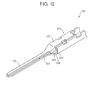
- FIG. 12 is a partial perspective view of the male connector terminal 100 suggested in the above-identified Japanese Patent.
- the male connector terminal 100 can be fabricated by a sheet made of copper alloy, for instance.
- the male connector terminal 100 integrally includes a barrel portion (not illustrated), a projecting contact portion 110 to be inserted into a female connector terminal, and a body portion 120 connecting the barrel portion and the projecting contact portion 110 to each other.
- the body portion 120 includes a top wall portion 121, and a sheet portion 122 lying immediately below the top wall portion 121.
- a reinforcement portion 123 extending from a distal end of the sheet portion 122 enters a proximal portion of the projecting contact portion 110.
- the male connector terminal 100 further includes a sidewall 124 between the top wall portion 121 and the projecting contact portion 110 to compress a side of the reinforcement portion 123.
- the sidewall 124 prevents the reinforcement portion 123 from slipping out of the projecting contact portion 110 and reinforces a proximal portion of the projecting contact portion 110.
- a connector terminal comprised of a single bent metal sheet, including a contact portion including a first sheet portion and a second sheet portion, the first and second sheet portions being folded to overlap one on another, a terminal body, and a connector portion connecting the terminal body and the contact portion to each other, the connector portion including a reinforcement portion covering therewith an end surface of the first sheet portion, an end surface of the second sheet portion, and at least a part of a surface of the second sheet portion in a proximal part of the contact portion.
- the reinforcement portion covers therewith an end surface of the first sheet portion, an end surface of the second sheet portion, and at least a part of a surface of the second sheet portion. That is, there is formed a three-layered structure at a proximal portion of the contact portion, and accordingly, at the connector portion.
- a strength of the connector portion against buckling can be further enhanced.
- the reinforcement portion covers therewith an entire surface of the second sheet portion.
- the reinforcement portion is formed with a recess at a surface thereof located above the second sheet portion.
- a lance formed at a housing can be engaged with the recess. Hence, it is possible to prevent the connector terminal from slipping out of the housing by engaging the lance to the recess.
- the reinforcement portion has a substantially L-shaped cross-section.
- the connector portion has a substantially quadrangular-pyramid cross-section inclining towards the contact portion from the terminal body.
- a single metal sheet for fabricating a connector terminal including at least a first area extending in parallel with a base line, a second area situated adjacent to the first area, a third area situated adjacent to the second area, and a fourth area situated adjacent to the third area, wherein a width at one of sides of the base line is equal to a width at the other side of the base line in the first area, a width at the one of sides of the base line is greater than the width of the first area, and a width at the other side of the base line is equal to the width of the first area in the second area, a width in the one of sides of the base line linearly increases from the width of the second area, and a width in the other side of the base line linearly increases from the width of the second area in the third area, and a width in the one of sides of the base line is equal to a final width of the third area, and a width in the other side of the base line linearly decreases from a final width of the third area
- a method of fabricating the above-mentioned connector terminal through the use of the above-mentioned single metal sheet including folding the first area at the other side of the base line around the base line onto the first area at the one of sides of the base line, and bending the second to fourth areas at the other side of the base line into a quadrangular pyramid, and folding the second to fourth areas at the one of sides of the base line onto the second to fourth areas at the other side of the base line.
- the reinforcement portion covers therewith an end surface of the first sheet portion, an end surface of the second sheet portion, and at least a part of a surface of the second sheet portion. That is, there is formed a three-layered structure at a proximal portion of the contact portion, and accordingly, at the connector portion.
- a strength of the connector portion against buckling can be further enhanced. Consequently, when the contact portion is inserted into a female connector terminal or when the connector terminal is inserted into a housing, the contact portion can be prevented from being bent or deformed at a proximal portion.
- the electric connector 10 illustrated in FIGs. 1 to 3 is used for an electric circuit equipped in an automobile, for instance.
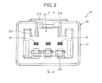
- the electric connector 10 includes a housing 20 to be fit into a female electric connector (not illustrated), and a connector terminal 30 (see FIG. 3 ) including a later-mentioned contact portion 33 extending into a space of the housing 20.
- the housing 20 can be fabricated by molding.
- the housing 20 includes a first portion 21 formed therein with a fitting space S1 into which a male housing is fit, and a second portion 22 formed therein with a terminal space S2 into which the connector terminal 30 is housed.
- the connector terminal 30 housed in the terminal space S2 extends a contact portion 33 thereof into the fitting space S1, as illustrated in FIG. 3 .
- the first portion 21 is in the form of a box, and has a rectangular opening.
- the first portion 211 is formed at inner surfaces thereof with projections 211 each having a rectangular cross-section, and a cut-out 212 having a rectangular cross-section in order to prevent a wrong male connector from being inserted into the fitting space S1 of the first portion 21, and further, to cause a male connector to be inserted into the fitting space S1 in a correct position when the male connector is attempted to be inserted into the fitting space S1 in an inclined position.
- edges of the cut-out 212 extend into the fitting space S1 to thereby define upright walls 213.
- a cover 214 covers therewith an opening formed by the cut-out 212.
- the second portion 22 is in the form of a rectangular parallelepiped having a thickness smaller than the same of the first portion 21 and a length longer than the same of the first portion 21.
- the second portion 22 is formed therein with the three terminal spaces S2 horizontally arranged.
- Each of the terminal spaces S2 is formed at a rear with an opening 221 through which the connector terminal 30 is inserted into the terminal space S2, as illustrated in FIG. 3 .
- Each of the terminal spaces S2 is tapered at a front thereof in line with a shape of a later-mentioned connector portion of the connector terminal 30.
- Each of the terminal spaces S2 is formed at an inner ceiling with a stepped portion 222 (see FIG. 3 ) for restricting the movement of the connector terminal 30 when the connector terminal 30 is inserted into the terminal space S2.
- Each of the terminal spaces S2 is formed at an inner floor with a lance 223 (see FIG. 3 ) for preventing the connector terminal 30 from slipping out of the housing 20.
- the connector terminal 30 comprises a male terminal to be inserted into a female terminal.
- the connector terminal 30 includes a wire connection portion 31, a main body 32, and a contact portion 33.
- the wire connection portion 31 includes a wire barrel portion 311 and a core barrel portion 312.
- a wire (not illustrated) put on a wire receiver 311a (see FIG. 6 ) is compressed and fixed by bending a pair of upwardly extending walls 311a and 311b onto the wire.
- a core of a wire (not illustrated) put on a core receiver 312a (see FIG. 6 ) is compressed and fixed by bending a pair of upwardly extending walls 312b and 312c onto the core such that the core and the walls 312b and 312c and hence the connector terminal 30 are electrically connected to each other.
- the main body 32 includes a terminal body 321 in the form of a square pipe, and a connector portion 322 connecting the terminal body 321 and the contact portion 333 to each other.
- the terminal body 321 includes a pair of sidewalls 321b perpendicularly extending from a ceiling 321a, and a pair of floors 321c extending horizontally and inwardly from the sidewalls 321b.
- the floors 321c overlap one on another.
- a closed space is formed in the terminal body 321 by the ceiling 321a, the sidewalls 321b and the floors 321c.
- a stabilizer 321b vertically stands from one of the sidewalls 321b in a part of the terminal body 321 for the purpose of avoiding the connector terminal 30 from being inserted into the housing 20 upside down.
- the single floor 321c is formed where the stabilizer 321d stands.
- the terminal body 321 is formed at the ceiling 321a with a projection 321e with which the stepped portion 222 (see FIG. 3 ) formed in the terminal space S2 is engaged.
- the projection 321e is in the form of a semicircular cone.
- the terminal body 321 is formed at the floors 321c with a recess 321f with which the lance 223 (see FIG. 3 ) formed in the terminal space S2 is engaged.
- the connector portion 322 has a substantially quadrangular-pyramid cross-section inclining towards the contact portion 33 from the terminal body 321.
- the connector portion 322 is designed tapered and extends from the terminal body 321 to the contact portion 33.
- the connector portion 322 includes a ceiling 322a (see FIG. 8 ) formed of a wall downwardly inclining from the ceiling 321a of the terminal body 321, a pair of sidewalls 322b and 322c (see FIG. 8 ) each having a gradually decreasing width, and thus, being in the form of a triangle, and a floor 322d (see FIG. 8 ) formed of a wall upwardly inclining from the floors 321c of the terminal body 321.
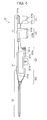
- the connector portion 322 includes an extending portion 3221 formed as an extension of the contact portion 33, and a reinforcement portion 3222.
- the extending portion 3221 comprises a first sheet portion 3221a and a second sheet portion 3221b.
- the first and second sheet portions 3221a and 3221b are folded to overlap one on another.
- the extending portion 3221 can be fabricated by folding a metal sheet into a U-shape.
- the reinforcement portion 3222 covers therewith an end surface 3221aa of the first sheet portion 3221a, an end surface 3221ba of the second sheet portion 3221b, and an entire surface 3221bb of the second sheet portion 3221b.
- the reinforcement portion 3222 has a substantially L-shaped cross-section, as illustrated in FIG. 8 .
- the reinforcement portion 3222 is formed within a proximal part of the contact portion 33, as illustrated in FIG. 7 .
- the extending portion 3221 gradually increases a width thereof to thereby extend to and define a part of the ceiling 322a, one of the sidewalls 322b, and the floor 322d.
- the reinforcement portion 3222 lies on the surface 3221bb of the second sheet portion 3221b to thereby define a part of the other of the sidewalls 322c and the floor 322d.
- the contact portion 33 defines a tab extending from the connector portion 322 to thereby be inserted into a female connector terminal.
- the connector terminal 30 can be fabricated from a single bent metal sheet. Specifically, the connector terminal 30 can be fabricated by punching an elastic metal sheet into a metal sheet 300 having such a predetermined shape as illustrated in FIG. 9 , and bending the metal sheet 300 into the three-dimensional shape.
- An order for fabricating the wire connection portion 31, the terminal body 32 and the contact portion 33 by bending the metal sheet 300 may be arbitrarily determined.
- the terminal body 32, the contact portion 33 and the wire connection portion 31 may be fabricated in this order.
- the wire connection portion 31, the terminal body 32 and the contact portion 33 may be fabricated in this order.
- the contact portion 33 may be first fabricated, and then, the terminal body 32 and the wire connection portion 31 may be concurrently fabricated.
- the wire connection portion 31, the terminal body 32 and the contact portion 33 may be concurrently fabricated.
- the wire connection portion 31 is fabricated by putting a round-bar die on the wire receiver 311a and the core receiver 312a, and bending both the walls 311b and 311c of the wire barrel portion 311 and the walls 312b and 312c of the core barrel portion 312 around the round-bar die.
- the walls 311b and 311c obliquely stand with the wire receiver 311a being a summit to thereby define the substantially V-shaped wire barrel portion 311.
- the walls 312b and 312c obliquely stand with the core receiver 312a being a summit to thereby define the substantially V-shaped core barrel portion 312.
- the terminal body 321 is fabricated by putting a square-bar die on the ceiling 321a of the terminal body 321, and bending the metal sheet 300 around the square-bar die. Specifically, the sidewalls 321b are bent onto the square-bar die. Then, the sidewalls 321b are further bent at distal portions thereof around the square-bar die to thereby define the floors 321c.
- the stabilizer 321d is fabricated by causing one of the sidewalls 321b to stand without being further bent.
- the metal sheet 300 is designed to have first to fourth areas to fabricate the connector portion 322 and the contact portion 33.
- the metal sheet includes a first area 300A extending in parallel with a base line L, a second area 300B situated adjacent to the first area 300A, a third area 300C situated adjacent to the second area 300B, and a fourth area 300D situated adjacent to the third area 300C.
- a width W1A at a side LR of the base line L is equal to a width W2A at the other side LS of the base line L.
- a width W2A at the side LR of the base line L is greater than the width W1A of the first area 300A, and a width W2B at the other side LS of the base line L is equal to the width W1A of the first area 300A.
- a width W3A in the side LR of the base line L linearly increases from the width W2A of the second area 300B, and a width W3B in the other side LS of the base line L linearly increases from the width W2B of the second area 300B.
- a width W4A in the side LR of the base line L is equal to a final and maximum width of the third area 300C, and a width W4B in the other side LS of the base line L linearly decreases from a final and maximum width of the third area 300C.
- the connector portion 322 and the contact portion 33 are fabricated by putting a tapered square-pole die on the metal sheet 300 such that a top of the die aligns with a top of the connector portion 322, and bending the metal sheet 300 around the die.
- the first area 300A is in the form of an elongate rectangle, and is formed at a distal end thereof with a Y-shaped cut-out.
- the first area 300A is folded one on another around the base line L. As illustrated in FIGs. 10 and 11 , the folded first area 300A defines the contact portion 33, and further defines the extending portion 3221 comprising the first sheet portion 3221a and the second sheet portion 3221b overlapping one on another.
- the extending portion 3221 is just an extension of the contact portion 33.
- the reinforcement portion 3222 upwardly extending and making touch with the end surfaces 3221aa and 3221ba is folded and compressed onto the second sheet portion 3221b (see FIG. 8 ).
- the extending portion 3221 and the reinforcement portion 3222 make close contact with each other at a distal end of the connector portion 322. That is, there is formed a three-layered structure including three metal sheets in a thickness-wise direction (see FIGs. 7 and 8 ).
- a triangular portion 3223 (the third area 300C and the fourth area 300D at the other side LS) is bent around the extending portion 3221 to thereby define the sidewall 322b and the floor 322d.
- a trapezoidal portion 3224 (the third area 300C and the fourth area 300D at the side LR) is bent around the extending portion 3221 to thereby define the sidewall 322c and the floor 322d.
- the reinforcement portion 3222 and the extending portion 3221 overlap one on another at a distal end of the connector portion 322 to thereby define a three-layered structure surrounded by the ceiling 322a, the sidewalls 322b and 322c, and the floor 322d.
- there is not formed an opening such as the opening 125 at a side of a portion through which the projecting contact portion 110 and the body portion 120 are connected to each other.
- the opening 125 causes the body portion 120 to be collapsed to thereby narrow the opening 125.
- the reinforcement portion 3222 since the reinforcement portion 3222 is bent around the extending portion 3221 so as not to form an opening such as the opening 125, the reinforcement portion 3222 reinforces the connector portion 322.
- the connector terminal 30 can have an enhanced strength against buckling.
- the reinforcement portion 3222 lies on the second sheet portion 3221b, the first and second sheet portions 3221a and 3221b make close contact with each other, ensuring enhancement in the strength of connector portion 322. Since the reinforcement portion 3222 lies on the second sheet portion 3221b, even if a gap between the first and second sheet portions 3221a and 3221b gradually grows bigger, a bending portion of the extending portion 3221 defines the sidewall 322b of the connector portion 322, and the reinforcement portion 3222 defines the sidewall 322c, ensuring a strength against a stress acting on the contact portion 33 in a thickness-wise direction.
- the terminal body 321 is formed with the recess 321f which is to be engaged with the lance 223 projecting into the terminal space S2 (see FIG. 3 ).
- the lance 223 is engaged with the recess 321f when the connector terminal 30 is inserted into the terminal space S2, and hence, the connector terminal 30 can be prevented from being slipped out of the housing 20.
- the recess 321f can be formed at a desired position by forming a recess at the metal sheet 300 (see FIG. 9 ), and winding the reinforcement portion 3222 around the extending portion 3221.
- the reinforcement portion 3222 is designed to cover therewith the entire surface 3221bb of the second sheet portion 3221b.
- the reinforcement portion 3222 may be designed to cover therewith a part of the surface 3221bb of the second sheet portion 3221b.
- the connector terminal in accordance with the present invention can be broadly employed in an electric connector used in an electric/electronic device industry and an automobile industry, as a part to be inserted into and electrically connected with a female connector terminal.
Landscapes
- Engineering & Computer Science (AREA)
- Manufacturing & Machinery (AREA)
- Connector Housings Or Holding Contact Members (AREA)
- Manufacturing Of Electrical Connectors (AREA)
- Coupling Device And Connection With Printed Circuit (AREA)
- Connections Effected By Soldering, Adhesion, Or Permanent Deformation (AREA)
Applications Claiming Priority (1)
| Application Number | Priority Date | Filing Date | Title |
|---|---|---|---|
| JP2013174572A JP5644919B1 (ja) | 2013-08-26 | 2013-08-26 | コネクタ端子およびその製造方法 |
Publications (3)
| Publication Number | Publication Date |
|---|---|
| EP2846403A2 true EP2846403A2 (de) | 2015-03-11 |
| EP2846403A3 EP2846403A3 (de) | 2015-05-20 |
| EP2846403B1 EP2846403B1 (de) | 2018-02-14 |
Family
ID=51301205
Family Applications (1)
| Application Number | Title | Priority Date | Filing Date |
|---|---|---|---|
| EP14180821.2A Active EP2846403B1 (de) | 2013-08-26 | 2014-08-13 | Anschlussklemme und Verfahren zur Herstellung davon |
Country Status (5)
| Country | Link |
|---|---|
| US (1) | US9281596B2 (de) |
| EP (1) | EP2846403B1 (de) |
| JP (1) | JP5644919B1 (de) |
| KR (1) | KR101613863B1 (de) |
| CN (1) | CN104425941B (de) |
Cited By (1)
| Publication number | Priority date | Publication date | Assignee | Title |
|---|---|---|---|---|
| EP3579347A1 (de) * | 2018-06-07 | 2019-12-11 | Yazaki Corporation | Anschluss und steckverbinder |
Families Citing this family (13)
| Publication number | Priority date | Publication date | Assignee | Title |
|---|---|---|---|---|
| JP5644919B1 (ja) * | 2013-08-26 | 2014-12-24 | 第一精工株式会社 | コネクタ端子およびその製造方法 |
| US9318836B2 (en) * | 2014-02-06 | 2016-04-19 | Dai-Ichi Seiko Co., Ltd. | Electric connector |
| JP5895973B2 (ja) * | 2014-06-12 | 2016-03-30 | 第一精工株式会社 | 導電端子 |
| USD742321S1 (en) * | 2014-07-09 | 2015-11-03 | Dai-Ichi Seiko Co., Ltd. | Electric connector |
| JP1521178S (de) * | 2014-07-11 | 2015-04-13 | ||
| JP2016062807A (ja) * | 2014-09-19 | 2016-04-25 | 住友電装株式会社 | 端子金具 |
| CN108155502B (zh) * | 2016-12-06 | 2024-04-30 | 泰科电子(上海)有限公司 | 连接端子及连接器 |
| JP7054432B2 (ja) * | 2017-07-12 | 2022-04-14 | 株式会社オートネットワーク技術研究所 | 雄端子金具及び雌端子金具 |
| JP7172938B2 (ja) * | 2019-09-30 | 2022-11-16 | 住友電装株式会社 | 雄端子、および雄コネクタ |
| JP1669104S (de) * | 2020-05-15 | 2020-09-28 | ||
| CN111916927B (zh) * | 2020-06-02 | 2021-11-16 | 番禺得意精密电子工业有限公司 | 电连接器及其端子 |
| CN112864668A (zh) * | 2021-01-12 | 2021-05-28 | 上海昆文连接器系统有限公司 | 一种汽车连接器的端子结构 |
| JP7685147B2 (ja) * | 2022-01-24 | 2025-05-29 | 住友電装株式会社 | 端子及びコネクタ |
Citations (1)
| Publication number | Priority date | Publication date | Assignee | Title |
|---|---|---|---|---|
| JP3478010B2 (ja) | 1996-07-26 | 2003-12-10 | 住友電装株式会社 | 雄側端子金具 |
Family Cites Families (30)
| Publication number | Priority date | Publication date | Assignee | Title |
|---|---|---|---|---|
| NL6911542A (de) * | 1969-07-28 | 1971-02-01 | ||
| JPS5749908A (en) | 1980-09-11 | 1982-03-24 | Olympus Optical Co Ltd | Method and device for detecting focus |
| DE4200109A1 (de) | 1992-01-04 | 1993-07-08 | Daut & Rietz Trw | Messerkontakt fuer elektrische steckverbinder |
| JPH0734563U (ja) * | 1993-12-08 | 1995-06-23 | 住友電装株式会社 | 雄型端子金具 |
| JP3046731B2 (ja) * | 1994-11-30 | 2000-05-29 | 矢崎総業株式会社 | 雄端子及び雄端子の製造方法 |
| JP3062928B2 (ja) * | 1996-04-26 | 2000-07-12 | 日本航空電子工業株式会社 | コンタクト |
| JP3272263B2 (ja) | 1997-04-18 | 2002-04-08 | タイコエレクトロニクスアンプ株式会社 | 端子振れ防止機構を備えたコネクタ |
| JP4132618B2 (ja) * | 2000-09-08 | 2008-08-13 | 矢崎総業株式会社 | 端子金具のタブ |
| DE10161514B4 (de) * | 2000-12-18 | 2007-04-12 | Sumitomo Wiring Systems, Ltd., Yokkaichi | Anschlussbuchse |
| JP3757801B2 (ja) * | 2001-02-07 | 2006-03-22 | 住友電装株式会社 | 雄コネクタ |
| JP2003036911A (ja) * | 2001-02-13 | 2003-02-07 | Yazaki Corp | 雄型端子金具 |
| JP2003036909A (ja) * | 2001-07-19 | 2003-02-07 | Yazaki Corp | コネクタ端子 |
| JP2003036910A (ja) | 2001-07-19 | 2003-02-07 | Yazaki Corp | コネクタ端子 |
| JP2003109718A (ja) * | 2001-09-27 | 2003-04-11 | Sumitomo Wiring Syst Ltd | 雄側端子金具の製造方法及び雄側端子金具 |
| JP3823811B2 (ja) * | 2001-11-22 | 2006-09-20 | 住友電装株式会社 | 雄側タブ |
| JP2003272744A (ja) * | 2002-03-19 | 2003-09-26 | Sumitomo Wiring Syst Ltd | 端子金具およびコネクタ |
| JP3814221B2 (ja) * | 2002-04-18 | 2006-08-23 | 住友電装株式会社 | 雄側端子金具 |
| JP3866631B2 (ja) * | 2002-07-30 | 2007-01-10 | 三菱電線工業株式会社 | 雄型棒状接続端子及びその製造方法 |
| JP4003577B2 (ja) * | 2002-08-07 | 2007-11-07 | 住友電装株式会社 | 雄端子金具 |
| US6755696B1 (en) * | 2003-04-14 | 2004-06-29 | Hon Hai Precision Ind. Co., Ltd | Electrical connector with improved terminal retention means |
| TW200501521A (en) * | 2003-04-16 | 2005-01-01 | J S T Mfg Co Ltd | Electric coupler and housing of plug-type connector |
| DE10349539B3 (de) * | 2003-10-22 | 2005-06-16 | Yazaki Europe Ltd., Hemel Hempstead | Elektrisches Kontaktelement |
| JP4743109B2 (ja) | 2006-12-18 | 2011-08-10 | 住友電装株式会社 | 端子金具及びコネクタ |
| US7780485B2 (en) * | 2008-08-12 | 2010-08-24 | Delphi Technologies, Inc. | Electrical connector |
| JP5396310B2 (ja) * | 2010-03-01 | 2014-01-22 | 住友電装株式会社 | コネクタ |
| JP5429100B2 (ja) * | 2010-08-06 | 2014-02-26 | 住友電装株式会社 | 端子金具 |
| JP6193122B2 (ja) * | 2010-08-20 | 2017-09-06 | デルフィ・インターナショナル・オペレーションズ・ルクセンブルク・エス・アー・エール・エル | 雄電気端子 |
| JP5745300B2 (ja) | 2011-03-17 | 2015-07-08 | 日本圧着端子製造株式会社 | 雄型端子及び雄型端子の接触部の形成方法 |
| JP5682519B2 (ja) * | 2011-09-14 | 2015-03-11 | 住友電装株式会社 | 端子金具 |
| JP5644919B1 (ja) * | 2013-08-26 | 2014-12-24 | 第一精工株式会社 | コネクタ端子およびその製造方法 |
-
2013
- 2013-08-26 JP JP2013174572A patent/JP5644919B1/ja active Active
-
2014
- 2014-08-13 EP EP14180821.2A patent/EP2846403B1/de active Active
- 2014-08-13 US US14/458,604 patent/US9281596B2/en active Active
- 2014-08-20 CN CN201410411891.XA patent/CN104425941B/zh active Active
- 2014-08-25 KR KR1020140110665A patent/KR101613863B1/ko not_active Expired - Fee Related
Patent Citations (1)
| Publication number | Priority date | Publication date | Assignee | Title |
|---|---|---|---|---|
| JP3478010B2 (ja) | 1996-07-26 | 2003-12-10 | 住友電装株式会社 | 雄側端子金具 |
Cited By (3)
| Publication number | Priority date | Publication date | Assignee | Title |
|---|---|---|---|---|
| EP3579347A1 (de) * | 2018-06-07 | 2019-12-11 | Yazaki Corporation | Anschluss und steckverbinder |
| CN110581370A (zh) * | 2018-06-07 | 2019-12-17 | 矢崎总业株式会社 | 端子和连接器 |
| US10622748B2 (en) | 2018-06-07 | 2020-04-14 | Yazaki Corporation | Terminal and connector |
Also Published As
| Publication number | Publication date |
|---|---|
| CN104425941B (zh) | 2016-08-24 |
| CN104425941A (zh) | 2015-03-18 |
| KR101613863B1 (ko) | 2016-04-20 |
| JP5644919B1 (ja) | 2014-12-24 |
| US9281596B2 (en) | 2016-03-08 |
| KR20150024280A (ko) | 2015-03-06 |
| EP2846403B1 (de) | 2018-02-14 |
| US20150056872A1 (en) | 2015-02-26 |
| EP2846403A3 (de) | 2015-05-20 |
| JP2015043286A (ja) | 2015-03-05 |
Similar Documents
| Publication | Publication Date | Title |
|---|---|---|
| EP2846403B1 (de) | Anschlussklemme und Verfahren zur Herstellung davon | |
| US20100035486A1 (en) | Terminal fitting | |
| JP3478010B2 (ja) | 雄側端子金具 | |
| US6679738B2 (en) | Female terminal | |
| JP5362296B2 (ja) | 端子金具 | |
| US6068527A (en) | Terminal and a mold for forming the terminal | |
| CN101645542B (zh) | 端子接头及其连接方法 | |
| JP2012054107A (ja) | 電線付き端子金具 | |
| JP5739744B2 (ja) | 端子金具 | |
| JP2011154944A (ja) | 雌型端子金具 | |
| JPH0982391A (ja) | 端子金具及び端子金具の製造方法 | |
| EP0649186A2 (de) | Elektrische Anschlussklemme zum Aufpressen an einen Leiter | |
| CN111799574A (zh) | 带端子的电线以及端子压接装置 | |
| JP2009152111A (ja) | 圧着端子およびそれを備えた端子付電線 | |
| US9356375B2 (en) | Male terminal fitting | |
| KR20160119689A (ko) | 코일단말의 접속구조 | |
| JP2014160606A (ja) | 圧着端子、圧着端子付き電線及びワイヤハーネス | |
| JP2012028149A (ja) | メス端子 | |
| WO2014112507A1 (ja) | 端子 | |
| WO2023204212A1 (ja) | 圧着前端子 | |
| JP2005038761A (ja) | 雌型端子 | |
| JP2002170619A (ja) | 端子金具 | |
| JP2007287615A (ja) | 端子金具 | |
| JPH0134283Y2 (de) | ||
| JP2025011868A (ja) | 端子金具 |
Legal Events
| Date | Code | Title | Description |
|---|---|---|---|
| 17P | Request for examination filed |
Effective date: 20140813 |
|
| AK | Designated contracting states |
Kind code of ref document: A2 Designated state(s): AL AT BE BG CH CY CZ DE DK EE ES FI FR GB GR HR HU IE IS IT LI LT LU LV MC MK MT NL NO PL PT RO RS SE SI SK SM TR |
|
| AX | Request for extension of the european patent |
Extension state: BA ME |
|
| PUAI | Public reference made under article 153(3) epc to a published international application that has entered the european phase |
Free format text: ORIGINAL CODE: 0009012 |
|
| PUAL | Search report despatched |
Free format text: ORIGINAL CODE: 0009013 |
|
| AK | Designated contracting states |
Kind code of ref document: A3 Designated state(s): AL AT BE BG CH CY CZ DE DK EE ES FI FR GB GR HR HU IE IS IT LI LT LU LV MC MK MT NL NO PL PT RO RS SE SI SK SM TR |
|
| AX | Request for extension of the european patent |
Extension state: BA ME |
|
| RIC1 | Information provided on ipc code assigned before grant |
Ipc: H01R 4/18 20060101AFI20150410BHEP Ipc: H01R 43/16 20060101ALI20150410BHEP Ipc: H01R 13/422 20060101ALN20150410BHEP Ipc: H01R 13/04 20060101ALI20150410BHEP |
|
| R17P | Request for examination filed (corrected) |
Effective date: 20151030 |
|
| RBV | Designated contracting states (corrected) |
Designated state(s): AL AT BE BG CH CY CZ DE DK EE ES FI FR GB GR HR HU IE IS IT LI LT LU LV MC MK MT NL NO PL PT RO RS SE SI SK SM TR |
|
| 17Q | First examination report despatched |
Effective date: 20160412 |
|
| RIC1 | Information provided on ipc code assigned before grant |
Ipc: H01R 13/04 20060101ALI20170717BHEP Ipc: H01R 43/16 20060101ALI20170717BHEP Ipc: H01R 13/422 20060101ALN20170717BHEP Ipc: H01R 4/18 20060101AFI20170717BHEP |
|
| GRAP | Despatch of communication of intention to grant a patent |
Free format text: ORIGINAL CODE: EPIDOSNIGR1 |
|
| INTG | Intention to grant announced |
Effective date: 20170830 |
|
| GRAS | Grant fee paid |
Free format text: ORIGINAL CODE: EPIDOSNIGR3 |
|
| GRAA | (expected) grant |
Free format text: ORIGINAL CODE: 0009210 |
|
| AK | Designated contracting states |
Kind code of ref document: B1 Designated state(s): AL AT BE BG CH CY CZ DE DK EE ES FI FR GB GR HR HU IE IS IT LI LT LU LV MC MK MT NL NO PL PT RO RS SE SI SK SM TR |
|
| REG | Reference to a national code |
Ref country code: GB Ref legal event code: FG4D |
|
| REG | Reference to a national code |
Ref country code: CH Ref legal event code: EP |
|
| REG | Reference to a national code |
Ref country code: IE Ref legal event code: FG4D |
|
| REG | Reference to a national code |
Ref country code: DE Ref legal event code: R096 Ref document number: 602014020877 Country of ref document: DE Ref country code: AT Ref legal event code: REF Ref document number: 970434 Country of ref document: AT Kind code of ref document: T Effective date: 20180315 |
|
| REG | Reference to a national code |
Ref country code: NL Ref legal event code: MP Effective date: 20180214 |
|
| REG | Reference to a national code |
Ref country code: AT Ref legal event code: MK05 Ref document number: 970434 Country of ref document: AT Kind code of ref document: T Effective date: 20180214 |
|
| PG25 | Lapsed in a contracting state [announced via postgrant information from national office to epo] |
Ref country code: FI Free format text: LAPSE BECAUSE OF FAILURE TO SUBMIT A TRANSLATION OF THE DESCRIPTION OR TO PAY THE FEE WITHIN THE PRESCRIBED TIME-LIMIT Effective date: 20180214 Ref country code: CY Free format text: LAPSE BECAUSE OF FAILURE TO SUBMIT A TRANSLATION OF THE DESCRIPTION OR TO PAY THE FEE WITHIN THE PRESCRIBED TIME-LIMIT Effective date: 20180214 Ref country code: NL Free format text: LAPSE BECAUSE OF FAILURE TO SUBMIT A TRANSLATION OF THE DESCRIPTION OR TO PAY THE FEE WITHIN THE PRESCRIBED TIME-LIMIT Effective date: 20180214 Ref country code: ES Free format text: LAPSE BECAUSE OF FAILURE TO SUBMIT A TRANSLATION OF THE DESCRIPTION OR TO PAY THE FEE WITHIN THE PRESCRIBED TIME-LIMIT Effective date: 20180214 Ref country code: LT Free format text: LAPSE BECAUSE OF FAILURE TO SUBMIT A TRANSLATION OF THE DESCRIPTION OR TO PAY THE FEE WITHIN THE PRESCRIBED TIME-LIMIT Effective date: 20180214 Ref country code: NO Free format text: LAPSE BECAUSE OF FAILURE TO SUBMIT A TRANSLATION OF THE DESCRIPTION OR TO PAY THE FEE WITHIN THE PRESCRIBED TIME-LIMIT Effective date: 20180514 Ref country code: HR Free format text: LAPSE BECAUSE OF FAILURE TO SUBMIT A TRANSLATION OF THE DESCRIPTION OR TO PAY THE FEE WITHIN THE PRESCRIBED TIME-LIMIT Effective date: 20180214 |
|
| REG | Reference to a national code |
Ref country code: FR Ref legal event code: PLFP Year of fee payment: 5 |
|
| PG25 | Lapsed in a contracting state [announced via postgrant information from national office to epo] |
Ref country code: GR Free format text: LAPSE BECAUSE OF FAILURE TO SUBMIT A TRANSLATION OF THE DESCRIPTION OR TO PAY THE FEE WITHIN THE PRESCRIBED TIME-LIMIT Effective date: 20180515 Ref country code: BG Free format text: LAPSE BECAUSE OF FAILURE TO SUBMIT A TRANSLATION OF THE DESCRIPTION OR TO PAY THE FEE WITHIN THE PRESCRIBED TIME-LIMIT Effective date: 20180514 Ref country code: RS Free format text: LAPSE BECAUSE OF FAILURE TO SUBMIT A TRANSLATION OF THE DESCRIPTION OR TO PAY THE FEE WITHIN THE PRESCRIBED TIME-LIMIT Effective date: 20180214 Ref country code: AT Free format text: LAPSE BECAUSE OF FAILURE TO SUBMIT A TRANSLATION OF THE DESCRIPTION OR TO PAY THE FEE WITHIN THE PRESCRIBED TIME-LIMIT Effective date: 20180214 Ref country code: SE Free format text: LAPSE BECAUSE OF FAILURE TO SUBMIT A TRANSLATION OF THE DESCRIPTION OR TO PAY THE FEE WITHIN THE PRESCRIBED TIME-LIMIT Effective date: 20180214 Ref country code: LV Free format text: LAPSE BECAUSE OF FAILURE TO SUBMIT A TRANSLATION OF THE DESCRIPTION OR TO PAY THE FEE WITHIN THE PRESCRIBED TIME-LIMIT Effective date: 20180214 |
|
| PG25 | Lapsed in a contracting state [announced via postgrant information from national office to epo] |
Ref country code: PL Free format text: LAPSE BECAUSE OF FAILURE TO SUBMIT A TRANSLATION OF THE DESCRIPTION OR TO PAY THE FEE WITHIN THE PRESCRIBED TIME-LIMIT Effective date: 20180214 Ref country code: EE Free format text: LAPSE BECAUSE OF FAILURE TO SUBMIT A TRANSLATION OF THE DESCRIPTION OR TO PAY THE FEE WITHIN THE PRESCRIBED TIME-LIMIT Effective date: 20180214 Ref country code: RO Free format text: LAPSE BECAUSE OF FAILURE TO SUBMIT A TRANSLATION OF THE DESCRIPTION OR TO PAY THE FEE WITHIN THE PRESCRIBED TIME-LIMIT Effective date: 20180214 Ref country code: AL Free format text: LAPSE BECAUSE OF FAILURE TO SUBMIT A TRANSLATION OF THE DESCRIPTION OR TO PAY THE FEE WITHIN THE PRESCRIBED TIME-LIMIT Effective date: 20180214 |
|
| REG | Reference to a national code |
Ref country code: DE Ref legal event code: R097 Ref document number: 602014020877 Country of ref document: DE |
|
| PG25 | Lapsed in a contracting state [announced via postgrant information from national office to epo] |
Ref country code: CZ Free format text: LAPSE BECAUSE OF FAILURE TO SUBMIT A TRANSLATION OF THE DESCRIPTION OR TO PAY THE FEE WITHIN THE PRESCRIBED TIME-LIMIT Effective date: 20180214 Ref country code: SK Free format text: LAPSE BECAUSE OF FAILURE TO SUBMIT A TRANSLATION OF THE DESCRIPTION OR TO PAY THE FEE WITHIN THE PRESCRIBED TIME-LIMIT Effective date: 20180214 Ref country code: DK Free format text: LAPSE BECAUSE OF FAILURE TO SUBMIT A TRANSLATION OF THE DESCRIPTION OR TO PAY THE FEE WITHIN THE PRESCRIBED TIME-LIMIT Effective date: 20180214 Ref country code: SM Free format text: LAPSE BECAUSE OF FAILURE TO SUBMIT A TRANSLATION OF THE DESCRIPTION OR TO PAY THE FEE WITHIN THE PRESCRIBED TIME-LIMIT Effective date: 20180214 |
|
| PLBE | No opposition filed within time limit |
Free format text: ORIGINAL CODE: 0009261 |
|
| STAA | Information on the status of an ep patent application or granted ep patent |
Free format text: STATUS: NO OPPOSITION FILED WITHIN TIME LIMIT |
|
| 26N | No opposition filed |
Effective date: 20181115 |
|
| PG25 | Lapsed in a contracting state [announced via postgrant information from national office to epo] |
Ref country code: SI Free format text: LAPSE BECAUSE OF FAILURE TO SUBMIT A TRANSLATION OF THE DESCRIPTION OR TO PAY THE FEE WITHIN THE PRESCRIBED TIME-LIMIT Effective date: 20180214 |
|
| PG25 | Lapsed in a contracting state [announced via postgrant information from national office to epo] |
Ref country code: MC Free format text: LAPSE BECAUSE OF FAILURE TO SUBMIT A TRANSLATION OF THE DESCRIPTION OR TO PAY THE FEE WITHIN THE PRESCRIBED TIME-LIMIT Effective date: 20180214 |
|
| REG | Reference to a national code |
Ref country code: CH Ref legal event code: PL |
|
| GBPC | Gb: european patent ceased through non-payment of renewal fee |
Effective date: 20180813 |
|
| PG25 | Lapsed in a contracting state [announced via postgrant information from national office to epo] |
Ref country code: LU Free format text: LAPSE BECAUSE OF NON-PAYMENT OF DUE FEES Effective date: 20180813 Ref country code: LI Free format text: LAPSE BECAUSE OF NON-PAYMENT OF DUE FEES Effective date: 20180831 Ref country code: CH Free format text: LAPSE BECAUSE OF NON-PAYMENT OF DUE FEES Effective date: 20180831 |
|
| REG | Reference to a national code |
Ref country code: BE Ref legal event code: MM Effective date: 20180831 |
|
| REG | Reference to a national code |
Ref country code: IE Ref legal event code: MM4A |
|
| PG25 | Lapsed in a contracting state [announced via postgrant information from national office to epo] |
Ref country code: IE Free format text: LAPSE BECAUSE OF NON-PAYMENT OF DUE FEES Effective date: 20180813 |
|
| PG25 | Lapsed in a contracting state [announced via postgrant information from national office to epo] |
Ref country code: BE Free format text: LAPSE BECAUSE OF NON-PAYMENT OF DUE FEES Effective date: 20180831 |
|
| PG25 | Lapsed in a contracting state [announced via postgrant information from national office to epo] |
Ref country code: GB Free format text: LAPSE BECAUSE OF NON-PAYMENT OF DUE FEES Effective date: 20180813 |
|
| PGFP | Annual fee paid to national office [announced via postgrant information from national office to epo] |
Ref country code: IT Payment date: 20190821 Year of fee payment: 6 Ref country code: FR Payment date: 20190822 Year of fee payment: 6 |
|
| PG25 | Lapsed in a contracting state [announced via postgrant information from national office to epo] |
Ref country code: MT Free format text: LAPSE BECAUSE OF NON-PAYMENT OF DUE FEES Effective date: 20180813 |
|
| PG25 | Lapsed in a contracting state [announced via postgrant information from national office to epo] |
Ref country code: TR Free format text: LAPSE BECAUSE OF FAILURE TO SUBMIT A TRANSLATION OF THE DESCRIPTION OR TO PAY THE FEE WITHIN THE PRESCRIBED TIME-LIMIT Effective date: 20180214 |
|
| PG25 | Lapsed in a contracting state [announced via postgrant information from national office to epo] |
Ref country code: HU Free format text: LAPSE BECAUSE OF FAILURE TO SUBMIT A TRANSLATION OF THE DESCRIPTION OR TO PAY THE FEE WITHIN THE PRESCRIBED TIME-LIMIT; INVALID AB INITIO Effective date: 20140813 Ref country code: PT Free format text: LAPSE BECAUSE OF FAILURE TO SUBMIT A TRANSLATION OF THE DESCRIPTION OR TO PAY THE FEE WITHIN THE PRESCRIBED TIME-LIMIT Effective date: 20180214 |
|
| PG25 | Lapsed in a contracting state [announced via postgrant information from national office to epo] |
Ref country code: MK Free format text: LAPSE BECAUSE OF NON-PAYMENT OF DUE FEES Effective date: 20180214 |
|
| PG25 | Lapsed in a contracting state [announced via postgrant information from national office to epo] |
Ref country code: IS Free format text: LAPSE BECAUSE OF FAILURE TO SUBMIT A TRANSLATION OF THE DESCRIPTION OR TO PAY THE FEE WITHIN THE PRESCRIBED TIME-LIMIT Effective date: 20180614 |
|
| PG25 | Lapsed in a contracting state [announced via postgrant information from national office to epo] |
Ref country code: IT Free format text: LAPSE BECAUSE OF NON-PAYMENT OF DUE FEES Effective date: 20200813 Ref country code: FR Free format text: LAPSE BECAUSE OF NON-PAYMENT OF DUE FEES Effective date: 20200831 |
|
| PGFP | Annual fee paid to national office [announced via postgrant information from national office to epo] |
Ref country code: DE Payment date: 20250820 Year of fee payment: 12 |