EP2846404A1 - Quetschverbinder für ein Erdungsgitter - Google Patents
Quetschverbinder für ein Erdungsgitter Download PDFInfo
- Publication number
- EP2846404A1 EP2846404A1 EP14182331.0A EP14182331A EP2846404A1 EP 2846404 A1 EP2846404 A1 EP 2846404A1 EP 14182331 A EP14182331 A EP 14182331A EP 2846404 A1 EP2846404 A1 EP 2846404A1
- Authority
- EP
- European Patent Office
- Prior art keywords
- connector
- trough
- electrical conductor
- body member
- swage
- Prior art date
- Legal status (The legal status is an assumption and is not a legal conclusion. Google has not performed a legal analysis and makes no representation as to the accuracy of the status listed.)
- Granted
Links
Images




Classifications
-
- H—ELECTRICITY
- H01—ELECTRIC ELEMENTS
- H01R—ELECTRICALLY-CONDUCTIVE CONNECTIONS; STRUCTURAL ASSOCIATIONS OF A PLURALITY OF MUTUALLY-INSULATED ELECTRICAL CONNECTING ELEMENTS; COUPLING DEVICES; CURRENT COLLECTORS
- H01R4/00—Electrically-conductive connections between two or more conductive members in direct contact, i.e. touching one another; Means for effecting or maintaining such contact; Electrically-conductive connections having two or more spaced connecting locations for conductors and using contact members penetrating insulation
- H01R4/10—Electrically-conductive connections between two or more conductive members in direct contact, i.e. touching one another; Means for effecting or maintaining such contact; Electrically-conductive connections having two or more spaced connecting locations for conductors and using contact members penetrating insulation effected solely by twisting, wrapping, bending, crimping, or other permanent deformation
-
- H—ELECTRICITY
- H01—ELECTRIC ELEMENTS
- H01R—ELECTRICALLY-CONDUCTIVE CONNECTIONS; STRUCTURAL ASSOCIATIONS OF A PLURALITY OF MUTUALLY-INSULATED ELECTRICAL CONNECTING ELEMENTS; COUPLING DEVICES; CURRENT COLLECTORS
- H01R11/00—Individual connecting elements providing two or more spaced connecting locations for conductive members which are, or may be, thereby interconnected, e.g. end pieces for wires or cables supported by the wire or cable and having means for facilitating electrical connection to some other wire, terminal, or conductive member, blocks of binding posts
- H01R11/11—End pieces or tapping pieces for wires, supported by the wire and for facilitating electrical connection to some other wire, terminal or conductive member
-
- H—ELECTRICITY
- H01—ELECTRIC ELEMENTS
- H01R—ELECTRICALLY-CONDUCTIVE CONNECTIONS; STRUCTURAL ASSOCIATIONS OF A PLURALITY OF MUTUALLY-INSULATED ELECTRICAL CONNECTING ELEMENTS; COUPLING DEVICES; CURRENT COLLECTORS
- H01R11/00—Individual connecting elements providing two or more spaced connecting locations for conductive members which are, or may be, thereby interconnected, e.g. end pieces for wires or cables supported by the wire or cable and having means for facilitating electrical connection to some other wire, terminal, or conductive member, blocks of binding posts
- H01R11/01—Individual connecting elements providing two or more spaced connecting locations for conductive members which are, or may be, thereby interconnected, e.g. end pieces for wires or cables supported by the wire or cable and having means for facilitating electrical connection to some other wire, terminal, or conductive member, blocks of binding posts characterised by the form or arrangement of the conductive interconnection between the connecting locations
-
- H—ELECTRICITY
- H01—ELECTRIC ELEMENTS
- H01R—ELECTRICALLY-CONDUCTIVE CONNECTIONS; STRUCTURAL ASSOCIATIONS OF A PLURALITY OF MUTUALLY-INSULATED ELECTRICAL CONNECTING ELEMENTS; COUPLING DEVICES; CURRENT COLLECTORS
- H01R11/00—Individual connecting elements providing two or more spaced connecting locations for conductive members which are, or may be, thereby interconnected, e.g. end pieces for wires or cables supported by the wire or cable and having means for facilitating electrical connection to some other wire, terminal, or conductive member, blocks of binding posts
- H01R11/03—Individual connecting elements providing two or more spaced connecting locations for conductive members which are, or may be, thereby interconnected, e.g. end pieces for wires or cables supported by the wire or cable and having means for facilitating electrical connection to some other wire, terminal, or conductive member, blocks of binding posts characterised by the relationship between the connecting locations
- H01R11/09—Individual connecting elements providing two or more spaced connecting locations for conductive members which are, or may be, thereby interconnected, e.g. end pieces for wires or cables supported by the wire or cable and having means for facilitating electrical connection to some other wire, terminal, or conductive member, blocks of binding posts characterised by the relationship between the connecting locations the connecting locations being identical
-
- H—ELECTRICITY
- H01—ELECTRIC ELEMENTS
- H01R—ELECTRICALLY-CONDUCTIVE CONNECTIONS; STRUCTURAL ASSOCIATIONS OF A PLURALITY OF MUTUALLY-INSULATED ELECTRICAL CONNECTING ELEMENTS; COUPLING DEVICES; CURRENT COLLECTORS
- H01R4/00—Electrically-conductive connections between two or more conductive members in direct contact, i.e. touching one another; Means for effecting or maintaining such contact; Electrically-conductive connections having two or more spaced connecting locations for conductors and using contact members penetrating insulation
- H01R4/10—Electrically-conductive connections between two or more conductive members in direct contact, i.e. touching one another; Means for effecting or maintaining such contact; Electrically-conductive connections having two or more spaced connecting locations for conductors and using contact members penetrating insulation effected solely by twisting, wrapping, bending, crimping, or other permanent deformation
- H01R4/18—Electrically-conductive connections between two or more conductive members in direct contact, i.e. touching one another; Means for effecting or maintaining such contact; Electrically-conductive connections having two or more spaced connecting locations for conductors and using contact members penetrating insulation effected solely by twisting, wrapping, bending, crimping, or other permanent deformation by crimping
- H01R4/183—Electrically-conductive connections between two or more conductive members in direct contact, i.e. touching one another; Means for effecting or maintaining such contact; Electrically-conductive connections having two or more spaced connecting locations for conductors and using contact members penetrating insulation effected solely by twisting, wrapping, bending, crimping, or other permanent deformation by crimping for cylindrical elongated bodies, e.g. cables having circular cross-section
-
- H—ELECTRICITY
- H01—ELECTRIC ELEMENTS
- H01R—ELECTRICALLY-CONDUCTIVE CONNECTIONS; STRUCTURAL ASSOCIATIONS OF A PLURALITY OF MUTUALLY-INSULATED ELECTRICAL CONNECTING ELEMENTS; COUPLING DEVICES; CURRENT COLLECTORS
- H01R4/00—Electrically-conductive connections between two or more conductive members in direct contact, i.e. touching one another; Means for effecting or maintaining such contact; Electrically-conductive connections having two or more spaced connecting locations for conductors and using contact members penetrating insulation
- H01R4/58—Electrically-conductive connections between two or more conductive members in direct contact, i.e. touching one another; Means for effecting or maintaining such contact; Electrically-conductive connections having two or more spaced connecting locations for conductors and using contact members penetrating insulation characterised by the form or material of the contacting members
- H01R4/64—Connections between or with conductive parts having primarily a non-electric function, e.g. frame, casing, rail
- H01R4/646—Connections between or with conductive parts having primarily a non-electric function, e.g. frame, casing, rail for cables or flexible cylindrical bodies
-
- H—ELECTRICITY
- H01—ELECTRIC ELEMENTS
- H01R—ELECTRICALLY-CONDUCTIVE CONNECTIONS; STRUCTURAL ASSOCIATIONS OF A PLURALITY OF MUTUALLY-INSULATED ELECTRICAL CONNECTING ELEMENTS; COUPLING DEVICES; CURRENT COLLECTORS
- H01R11/00—Individual connecting elements providing two or more spaced connecting locations for conductive members which are, or may be, thereby interconnected, e.g. end pieces for wires or cables supported by the wire or cable and having means for facilitating electrical connection to some other wire, terminal, or conductive member, blocks of binding posts
- H01R11/11—End pieces or tapping pieces for wires, supported by the wire and for facilitating electrical connection to some other wire, terminal or conductive member
- H01R11/32—End pieces with two or more terminations
-
- H—ELECTRICITY
- H01—ELECTRIC ELEMENTS
- H01R—ELECTRICALLY-CONDUCTIVE CONNECTIONS; STRUCTURAL ASSOCIATIONS OF A PLURALITY OF MUTUALLY-INSULATED ELECTRICAL CONNECTING ELEMENTS; COUPLING DEVICES; CURRENT COLLECTORS
- H01R2101/00—One pole
Definitions
- This invention relates to the field of connectors for electrical conductors, and, more particularly to swaged connectors for use in a grounding grid.
- Substations in electrical power distribution systems require a properly designed and installed grounding system to insure reliable performance.
- Grounding is typically accomplished with a grid of electrical conductors buried in the soil.
- the substation equipment is connected to the grounding grid by means of cables, rods or bars that are securely connected to the grid.
- Connections within and to the grid are typically made using special purpose connectors that are crimped to a grid conductor.
- the crimping process used to secure a connector concentrates the compressive force at one or a few locations around the circumference of the conductor. This localized concentration of force can result in a poor electrical connection.
- Swaging is a process that distributes compressive force evenly around the circumference of a cylindrical body. Therefore, a properly swaged connector will generally provide a superior connection in comparison to a crimped connector.
- the present invention provides a family of swaged connectors with particular application for joining segments of copper cable that make up a subterranean grounding grid in an electrical utility substation. Removable inserts or “lids" allow the connectors to join onto existing continuous cables prior to installation.
- the connectors comprise a body member with at least one swage region having a trough for receiving an electrical conductor, the swage region having an opening extending the length of the trough to allow insertion, in a radial direction, of the electrical conductor into the trough.
- An insert is configured for mating engagement with the opening in the swage region, such that, when the insert is mated with the body member, an electrical conductor disposed within the trough is radially entrapped in the connector.
- the connector body and insert have a cylindrical outer surface in the swage region to facilitate swaging the connector to secure it to the electrical conductor.
- the connector may be configured as a lap splice, tee or elbow.
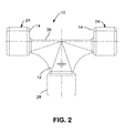
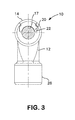
- FIGS 1-3 illustrate a split tee grounding connector 10.
- the purpose of this connector is to join cable (copper-clad, copper stranded or solid copper) and/or ground rod (solid copper or copper clad/bonded) or rebar in a 90° configuration.
- Connector 10 comprises a body member 12 and a pair of inserts or "lids" 14.
- the body member and inserts are preferably made of high-purity copper, such as electrolytic tough pitch copper.
- connector body 12 With the inserts removed, connector body 12 has a nearly semi-cylindrical trough 16 for receiving a conductor cable 17. In one specific example, the diameter of the cylindrical trough is 0.594".
- Inserts 14 are configured with a complementary cylindrical inner surface 18 such that the assembled connector has a complete cylindrical inner surface surrounding the cable in swage regions 24. Inserts 14 have flanges 20 that are received in corresponding slots 22 in body member 12. These flanges and slots define keying surfaces that assist axial insertion of the inserts into the body member and prevent the inserts from being removed radially. The flanges and slots may also be configured with an axial taper toward the center of the body member to prevent the inserts from sliding all the way through the slots and to temporarily wedge the inserts in the slots during installation prior to swaging.
- Connector 10 is attached to a cable by first removing the inserts 14 and then placing the cable into trough 16. Inserts 14 are then inserted axially into slots 22. Swage regions 24 of the connector are then inserted into a suitable swage tool and uniformly radially compressed to retain the cable. In one specific example, the swage regions of the connector are 1.00" wide and have an outside diameter of 1.25". The swaging operation is preferably performed using the 360° Radial Swage Tool manufactured by DMC Power, Inc. of Gardena, Calif.
- the center section 26 of the body member between the two swage regions 24 does not fully encircle the cable for the purpose of reducing the volume of material in the connector.
- the resulting shorter lengths of the inserts 14 increase the strength of the connector by minimizing the overturning moment created under a tensile load between the 90° portions of the connector.
- Bottom tap 28 does not require an insert since the cable, rod or rebar can be inserted axially.
- the outside diameter of the bottom tap is sized for the swaging tool and will generally have the same outside diameter as swaging regions 24.
- a hole 30 is drilled to the center of the connector. This hole serves to verify proper insertion depth during installation and allows moisture to escape after installation.
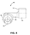
- Figure 4 and 5 illustrate an offset split elbow/tee/cross connector 40.
- This connector is designed to join cable and/or ground rod or rebar in a 90° offset configuration.
- the construction and assembly of connector 40 is essentially the same as for connector 10 described above.
- the area behind the two swage regions 44 of body member 42 has been removed for material reduction and to minimize the overturning moment between the 90° portions.
- Figure 6 and 7 illustrate a split parallel grounding connector 50.
- Two parallel holes 54 and 56 allow the connector to be used in various geometries with flexible cable, such as tee, offset cross, splice, or parallel continuous cable.
- connector 50 can be used with cable, ground rod and/or rebar.
- Two cutaway sections 58 and 60 on either side of connector body 52 serve dual purposes. First, they reduce the amount of material in the connector, allowing a smaller required force to plastically deform during swaging. Second, they provide an area where the fitting can further compress, even after the cable and connector interface have been fully compressed. This allows for range taking, i.e., the ability to accommodate various cable sizes with a single hole diameter.
- connector 50 does not have separate swage regions for the connected conductors. Instead, the entire connector body, with inserts 14, is inserted into a suitable swage tool and uniformly radially compressed to retain both of the conductors. In one specific example, the outside diameter of connector 50 is 2.00".
Landscapes
- Connections Effected By Soldering, Adhesion, Or Permanent Deformation (AREA)
- Details Of Connecting Devices For Male And Female Coupling (AREA)
- Cable Accessories (AREA)
- Multi-Conductor Connections (AREA)
- Connector Housings Or Holding Contact Members (AREA)
- Coupling Device And Connection With Printed Circuit (AREA)
Priority Applications (5)
| Application Number | Priority Date | Filing Date | Title |
|---|---|---|---|
| SM20170044T SMT201700044T1 (it) | 2013-09-10 | 2014-08-26 | Connettori a pressare per griglia di messa a massa |
| SI201430128A SI2846404T1 (sl) | 2013-09-10 | 2014-08-26 | Krčeni konektorji za ozemljitveno mrežo |
| PL14182331T PL2846404T3 (pl) | 2013-09-10 | 2014-08-26 | Zakotwione złącza do sieci uziemiającej |
| RS20161195A RS55536B1 (sr) | 2013-09-10 | 2014-08-26 | Stegnuti konektori mreže za uzemljenje |
| HRP20161798TT HRP20161798T1 (hr) | 2013-09-10 | 2016-12-27 | Uprešani priključci za uzemljenje mreže |
Applications Claiming Priority (1)
| Application Number | Priority Date | Filing Date | Title |
|---|---|---|---|
| US14/023,369 US9343819B2 (en) | 2013-09-10 | 2013-09-10 | Swaged connectors for a grounding grid |
Publications (2)
| Publication Number | Publication Date |
|---|---|
| EP2846404A1 true EP2846404A1 (de) | 2015-03-11 |
| EP2846404B1 EP2846404B1 (de) | 2016-10-12 |
Family
ID=51421851
Family Applications (1)
| Application Number | Title | Priority Date | Filing Date |
|---|---|---|---|
| EP14182331.0A Active EP2846404B1 (de) | 2013-09-10 | 2014-08-26 | Quetschverbinder für ein Erdungsgitter |
Country Status (15)
| Country | Link |
|---|---|
| US (1) | US9343819B2 (de) |
| EP (1) | EP2846404B1 (de) |
| CN (1) | CN104425912B (de) |
| BR (1) | BR102014022372B1 (de) |
| CY (1) | CY1118397T1 (de) |
| DK (1) | DK2846404T3 (de) |
| ES (1) | ES2610728T3 (de) |
| HR (1) | HRP20161798T1 (de) |
| HU (1) | HUE030262T2 (de) |
| LT (1) | LT2846404T (de) |
| PL (1) | PL2846404T3 (de) |
| PT (1) | PT2846404T (de) |
| RS (1) | RS55536B1 (de) |
| SI (1) | SI2846404T1 (de) |
| SM (2) | SMT201700044T1 (de) |
Cited By (1)
| Publication number | Priority date | Publication date | Assignee | Title |
|---|---|---|---|---|
| EP4354663A1 (de) * | 2022-10-13 | 2024-04-17 | Wolf Neumann-Henneberg | Quetschverbinder zu einem mechanischen und elektrisch leitenden verbinden eines elektrischen anschlusskontakts mit einem elektrischen leiter und quetschverbindung eines elektrischen anschlusskontakts mit einem elektrischen leiter |
Families Citing this family (7)
| Publication number | Priority date | Publication date | Assignee | Title |
|---|---|---|---|---|
| US9343819B2 (en) * | 2013-09-10 | 2016-05-17 | Dmc Power, Inc. | Swaged connectors for a grounding grid |
| USD886060S1 (en) * | 2018-01-19 | 2020-06-02 | Cps Technology Holdings, Llc | Battery vent adapter |
| US10297942B1 (en) | 2018-01-30 | 2019-05-21 | Afl Telecommunications Llc | Grounding connectors |
| US10985474B2 (en) * | 2018-08-06 | 2021-04-20 | Panduit Corp. | Grounding connector with lock joint |
| CN112510430A (zh) * | 2020-12-15 | 2021-03-16 | 中车建设工程有限公司 | 市域铁路信号贯通地线连接器 |
| US12586966B1 (en) | 2023-08-02 | 2026-03-24 | David NEWELL | Electrical cable splicing device |
| US20250112408A1 (en) * | 2023-09-28 | 2025-04-03 | Abb Schweiz Ag | Grounding Ring |
Citations (5)
| Publication number | Priority date | Publication date | Assignee | Title |
|---|---|---|---|---|
| DE667027C (de) * | 1934-12-28 | 1938-11-03 | Bayernwerk A G | Verbindungsklemme fuer gleichachsig liegende elektrische Freileitungsseile |
| US2995615A (en) * | 1955-09-06 | 1961-08-08 | British Insulated Callenders | Electric connectors |
| US3088761A (en) * | 1962-04-25 | 1963-05-07 | Aluminum Co Of America | Compressibly deformable connectors |
| US3185762A (en) * | 1962-12-21 | 1965-05-25 | Anderson Electric Corp | Cable connectors |
| FR2057638A5 (de) * | 1969-08-04 | 1971-05-21 | Pfisterer Elektrotech Karl |
Family Cites Families (13)
| Publication number | Priority date | Publication date | Assignee | Title |
|---|---|---|---|---|
| US1407477A (en) * | 1922-02-21 | Bentley a | ||
| US2106724A (en) * | 1935-03-16 | 1938-02-01 | Burton H Cope | Connecter |
| US3297817A (en) * | 1964-12-03 | 1967-01-10 | Irvin E Stier | Electrical conductors angularly joined with sheet metal connector having struck out tabs |
| CN2413402Y (zh) * | 1999-11-19 | 2001-01-03 | 冯检保 | 机械锁紧式t形连接头 |
| US6909049B2 (en) * | 2002-05-03 | 2005-06-21 | Fci Americas Technologies, Inc. | Electrical connector for angled conductors |
| CN201018013Y (zh) * | 2007-03-29 | 2008-02-06 | 王芹 | 一种t型接线夹 |
| US7906046B2 (en) | 2008-04-04 | 2011-03-15 | Panduit Corp. | Antioxidant joint compound and method for forming an electrical connection |
| CN201466245U (zh) * | 2009-08-19 | 2010-05-12 | 保定合力达应用化学有限公司 | 一种操作便捷的电缆插拔头 |
| CN101894659A (zh) * | 2009-09-03 | 2010-11-24 | 刘传云 | 可带电分离式接插件t型后头 |
| CN201533025U (zh) * | 2009-10-16 | 2010-07-21 | 周明 | 电力接地网 |
| CN201549617U (zh) * | 2009-11-03 | 2010-08-11 | 刘衍生 | 多连接头电力节能连接器 |
| CN201812951U (zh) * | 2010-07-12 | 2011-04-27 | 河南省电力公司郑州供电公司 | 压接式t型线夹 |
| US9343819B2 (en) * | 2013-09-10 | 2016-05-17 | Dmc Power, Inc. | Swaged connectors for a grounding grid |
-
2013
- 2013-09-10 US US14/023,369 patent/US9343819B2/en active Active
-
2014
- 2014-08-26 PL PL14182331T patent/PL2846404T3/pl unknown
- 2014-08-26 ES ES14182331.0T patent/ES2610728T3/es active Active
- 2014-08-26 SI SI201430128A patent/SI2846404T1/sl unknown
- 2014-08-26 DK DK14182331.0T patent/DK2846404T3/en active
- 2014-08-26 HU HUE14182331A patent/HUE030262T2/en unknown
- 2014-08-26 LT LTEP14182331.0T patent/LT2846404T/lt unknown
- 2014-08-26 SM SM20170044T patent/SMT201700044T1/it unknown
- 2014-08-26 RS RS20161195A patent/RS55536B1/sr unknown
- 2014-08-26 PT PT141823310T patent/PT2846404T/pt unknown
- 2014-08-26 EP EP14182331.0A patent/EP2846404B1/de active Active
- 2014-09-10 BR BR102014022372-0A patent/BR102014022372B1/pt active IP Right Grant
- 2014-09-10 CN CN201410459043.6A patent/CN104425912B/zh active Active
-
2016
- 2016-12-27 HR HRP20161798TT patent/HRP20161798T1/hr unknown
- 2016-12-30 CY CY20161101362T patent/CY1118397T1/el unknown
-
2017
- 2017-01-20 SM SM201700044T patent/SMT201700044B/it unknown
Patent Citations (5)
| Publication number | Priority date | Publication date | Assignee | Title |
|---|---|---|---|---|
| DE667027C (de) * | 1934-12-28 | 1938-11-03 | Bayernwerk A G | Verbindungsklemme fuer gleichachsig liegende elektrische Freileitungsseile |
| US2995615A (en) * | 1955-09-06 | 1961-08-08 | British Insulated Callenders | Electric connectors |
| US3088761A (en) * | 1962-04-25 | 1963-05-07 | Aluminum Co Of America | Compressibly deformable connectors |
| US3185762A (en) * | 1962-12-21 | 1965-05-25 | Anderson Electric Corp | Cable connectors |
| FR2057638A5 (de) * | 1969-08-04 | 1971-05-21 | Pfisterer Elektrotech Karl |
Cited By (2)
| Publication number | Priority date | Publication date | Assignee | Title |
|---|---|---|---|---|
| EP4354663A1 (de) * | 2022-10-13 | 2024-04-17 | Wolf Neumann-Henneberg | Quetschverbinder zu einem mechanischen und elektrisch leitenden verbinden eines elektrischen anschlusskontakts mit einem elektrischen leiter und quetschverbindung eines elektrischen anschlusskontakts mit einem elektrischen leiter |
| US12658607B2 (en) | 2022-10-13 | 2026-06-16 | Aknh Kontaktsysteme Gmbh | Crimp connector for mechanically and electrically conductively connecting an electrical connecting contact to an electrical conductor, and crimp connection of an electrical connecting contact to an electrical conductor |
Also Published As
| Publication number | Publication date |
|---|---|
| HRP20161798T1 (hr) | 2017-02-24 |
| EP2846404B1 (de) | 2016-10-12 |
| DK2846404T3 (en) | 2017-01-30 |
| CN104425912A (zh) | 2015-03-18 |
| PT2846404T (pt) | 2017-01-09 |
| BR102014022372B1 (pt) | 2021-09-21 |
| US9343819B2 (en) | 2016-05-17 |
| CN104425912B (zh) | 2017-12-19 |
| SMT201700044T1 (it) | 2017-03-08 |
| BR102014022372A2 (pt) | 2015-09-15 |
| SMT201700044B (it) | 2017-03-08 |
| SI2846404T1 (sl) | 2017-02-28 |
| PL2846404T3 (pl) | 2017-06-30 |
| ES2610728T3 (es) | 2017-05-03 |
| RS55536B1 (sr) | 2017-05-31 |
| LT2846404T (lt) | 2017-03-27 |
| CY1118397T1 (el) | 2017-06-28 |
| US20150072574A1 (en) | 2015-03-12 |
| HUE030262T2 (en) | 2017-04-28 |
Similar Documents
| Publication | Publication Date | Title |
|---|---|---|
| EP2846404B1 (de) | Quetschverbinder für ein Erdungsgitter | |
| US3184535A (en) | Compression connector for joining wires | |
| EP2115828B1 (de) | Geriffelte innenhülle für einen kabelstecker | |
| US10218131B2 (en) | Right angle coaxial cable and connector assembly | |
| US6168455B1 (en) | Coaxial cable connector | |
| US7342175B2 (en) | Electrical connector | |
| US7874881B1 (en) | Full tension swaged connector | |
| CN105144485B (zh) | 受控压缩管 | |
| EP2745353B1 (de) | Adaptierter elektrischer steckverbinder zur aufnahme von kabeln mit verschiedenen durchmessern | |
| EP1935071B1 (de) | Elektrischer steckverbinder | |
| EP3430686B1 (de) | Mehrschichtiger kabelspleiss | |
| EP2560239B1 (de) | Verfahren zum Anbringen eines Verbinders an ein elektrisches Kabel | |
| RU2531370C2 (ru) | Выдерживающий полную нагрузку на растяжение обжатый соединитель для армированного кабеля | |
| CA2920762C (en) | Swaged connectors for a grounding grid | |
| US7699645B1 (en) | Connector for multistranded insulated conductor cable | |
| US20150068786A1 (en) | Repair sleeve | |
| US7531747B2 (en) | Energy directing unitized core grip for electrical connector | |
| CA3018080C (en) | Multi-layer cable splice | |
| US20030148670A1 (en) | Electrical wedge connector | |
| CN108565597A (zh) | 一种高效的射频同轴连接器的安装结构 |
Legal Events
| Date | Code | Title | Description |
|---|---|---|---|
| 17P | Request for examination filed |
Effective date: 20141001 |
|
| AK | Designated contracting states |
Kind code of ref document: A1 Designated state(s): AL AT BE BG CH CY CZ DE DK EE ES FI FR GB GR HR HU IE IS IT LI LT LU LV MC MK MT NL NO PL PT RO RS SE SI SK SM TR |
|
| AX | Request for extension of the european patent |
Extension state: BA ME |
|
| PUAI | Public reference made under article 153(3) epc to a published international application that has entered the european phase |
Free format text: ORIGINAL CODE: 0009012 |
|
| GRAP | Despatch of communication of intention to grant a patent |
Free format text: ORIGINAL CODE: EPIDOSNIGR1 |
|
| RIC1 | Information provided on ipc code assigned before grant |
Ipc: H01R 4/18 20060101AFI20160106BHEP Ipc: H01R 101/00 20060101ALN20160106BHEP Ipc: H01R 11/09 20060101ALI20160106BHEP Ipc: H01R 4/64 20060101ALI20160106BHEP Ipc: H01R 11/32 20060101ALN20160106BHEP Ipc: H01R 11/01 20060101ALI20160106BHEP |
|
| RIC1 | Information provided on ipc code assigned before grant |
Ipc: H01R 4/64 20060101ALI20160112BHEP Ipc: H01R 11/09 20060101ALI20160112BHEP Ipc: H01R 101/00 20060101ALN20160112BHEP Ipc: H01R 4/18 20060101AFI20160112BHEP Ipc: H01R 11/32 20060101ALN20160112BHEP Ipc: H01R 11/01 20060101ALI20160112BHEP |
|
| RIC1 | Information provided on ipc code assigned before grant |
Ipc: H01R 4/18 20060101AFI20160118BHEP Ipc: H01R 11/09 20060101ALI20160118BHEP Ipc: H01R 11/32 20060101ALN20160118BHEP Ipc: H01R 4/64 20060101ALI20160118BHEP Ipc: H01R 11/01 20060101ALI20160118BHEP Ipc: H01R 101/00 20060101ALN20160118BHEP |
|
| INTG | Intention to grant announced |
Effective date: 20160201 |
|
| GRAS | Grant fee paid |
Free format text: ORIGINAL CODE: EPIDOSNIGR3 |
|
| GRAA | (expected) grant |
Free format text: ORIGINAL CODE: 0009210 |
|
| AK | Designated contracting states |
Kind code of ref document: B1 Designated state(s): AL AT BE BG CH CY CZ DE DK EE ES FI FR GB GR HR HU IE IS IT LI LT LU LV MC MK MT NL NO PL PT RO RS SE SI SK SM TR |
|
| REG | Reference to a national code |
Ref country code: GB Ref legal event code: FG4D |
|
| REG | Reference to a national code |
Ref country code: CH Ref legal event code: EP |
|
| REG | Reference to a national code |
Ref country code: AT Ref legal event code: REF Ref document number: 837244 Country of ref document: AT Kind code of ref document: T Effective date: 20161015 |
|
| REG | Reference to a national code |
Ref country code: IE Ref legal event code: FG4D |
|
| REG | Reference to a national code |
Ref country code: DE Ref legal event code: R096 Ref document number: 602014004181 Country of ref document: DE |
|
| REG | Reference to a national code |
Ref country code: HR Ref legal event code: TUEP Ref document number: P20161798 Country of ref document: HR |
|
| REG | Reference to a national code |
Ref country code: NL Ref legal event code: FP |
|
| REG | Reference to a national code |
Ref country code: PT Ref legal event code: SC4A Ref document number: 2846404 Country of ref document: PT Date of ref document: 20170109 Kind code of ref document: T Free format text: AVAILABILITY OF NATIONAL TRANSLATION Effective date: 20161230 Ref country code: RO Ref legal event code: EPE |
|
| REG | Reference to a national code |
Ref country code: DK Ref legal event code: T3 Effective date: 20170126 |
|
| REG | Reference to a national code |
Ref country code: SE Ref legal event code: TRGR |
|
| REG | Reference to a national code |
Ref country code: EE Ref legal event code: FG4A Ref document number: E013054 Country of ref document: EE Effective date: 20161222 |
|
| REG | Reference to a national code |
Ref country code: NO Ref legal event code: T2 Effective date: 20161012 |
|
| REG | Reference to a national code |
Ref country code: HR Ref legal event code: T1PR Ref document number: P20161798 Country of ref document: HR |
|
| REG | Reference to a national code |
Ref country code: HU Ref legal event code: AG4A Ref document number: E030262 Country of ref document: HU |
|
| REG | Reference to a national code |
Ref country code: ES Ref legal event code: FG2A Ref document number: 2610728 Country of ref document: ES Kind code of ref document: T3 Effective date: 20170503 |
|
| REG | Reference to a national code |
Ref country code: SK Ref legal event code: T3 Ref document number: E 23005 Country of ref document: SK |
|
| REG | Reference to a national code |
Ref country code: DE Ref legal event code: R097 Ref document number: 602014004181 Country of ref document: DE |
|
| PLBE | No opposition filed within time limit |
Free format text: ORIGINAL CODE: 0009261 |
|
| STAA | Information on the status of an ep patent application or granted ep patent |
Free format text: STATUS: NO OPPOSITION FILED WITHIN TIME LIMIT |
|
| REG | Reference to a national code |
Ref country code: FR Ref legal event code: PLFP Year of fee payment: 4 |
|
| 26N | No opposition filed |
Effective date: 20170713 |
|
| PG25 | Lapsed in a contracting state [announced via postgrant information from national office to epo] |
Ref country code: RS Free format text: LAPSE BECAUSE OF NON-PAYMENT OF DUE FEES Effective date: 20180305 |
|
| REG | Reference to a national code |
Ref country code: FR Ref legal event code: PLFP Year of fee payment: 5 |
|
| REG | Reference to a national code |
Ref country code: AT Ref legal event code: UEP Ref document number: 837244 Country of ref document: AT Kind code of ref document: T Effective date: 20161012 |
|
| REG | Reference to a national code |
Ref country code: HR Ref legal event code: ODRP Ref document number: P20161798 Country of ref document: HR Payment date: 20190807 Year of fee payment: 6 |
|
| REG | Reference to a national code |
Ref country code: HR Ref legal event code: ODRP Ref document number: P20161798 Country of ref document: HR Payment date: 20200806 Year of fee payment: 7 |
|
| REG | Reference to a national code |
Ref country code: HR Ref legal event code: ODRP Ref document number: P20161798 Country of ref document: HR Payment date: 20210804 Year of fee payment: 8 |
|
| REG | Reference to a national code |
Ref country code: HR Ref legal event code: ODRP Ref document number: P20161798 Country of ref document: HR Payment date: 20220802 Year of fee payment: 9 |
|
| P01 | Opt-out of the competence of the unified patent court (upc) registered |
Effective date: 20230526 |
|
| REG | Reference to a national code |
Ref country code: HR Ref legal event code: ODRP Ref document number: P20161798 Country of ref document: HR Payment date: 20230802 Year of fee payment: 10 |
|
| REG | Reference to a national code |
Ref country code: HR Ref legal event code: ODRP Ref document number: P20161798 Country of ref document: HR Payment date: 20240801 Year of fee payment: 11 |
|
| PGFP | Annual fee paid to national office [announced via postgrant information from national office to epo] |
Ref country code: NL Payment date: 20250826 Year of fee payment: 12 Ref country code: LU Payment date: 20250827 Year of fee payment: 12 |
|
| PGFP | Annual fee paid to national office [announced via postgrant information from national office to epo] |
Ref country code: HU Payment date: 20250807 Year of fee payment: 12 |
|
| REG | Reference to a national code |
Ref country code: HR Ref legal event code: ODRP Ref document number: P20161798 Country of ref document: HR Payment date: 20250820 Year of fee payment: 12 |
|
| PGFP | Annual fee paid to national office [announced via postgrant information from national office to epo] |
Ref country code: SM Payment date: 20250825 Year of fee payment: 12 |
|
| PGFP | Annual fee paid to national office [announced via postgrant information from national office to epo] |
Ref country code: ES Payment date: 20250901 Year of fee payment: 12 Ref country code: PT Payment date: 20250805 Year of fee payment: 12 Ref country code: FI Payment date: 20250825 Year of fee payment: 12 |
|
| PGFP | Annual fee paid to national office [announced via postgrant information from national office to epo] |
Ref country code: LT Payment date: 20250731 Year of fee payment: 12 Ref country code: DK Payment date: 20250825 Year of fee payment: 12 Ref country code: DE Payment date: 20250827 Year of fee payment: 12 |
|
| PGFP | Annual fee paid to national office [announced via postgrant information from national office to epo] |
Ref country code: MC Payment date: 20250804 Year of fee payment: 12 Ref country code: NO Payment date: 20250827 Year of fee payment: 12 Ref country code: GR Payment date: 20250826 Year of fee payment: 12 |
|
| PGFP | Annual fee paid to national office [announced via postgrant information from national office to epo] |
Ref country code: PL Payment date: 20250807 Year of fee payment: 12 Ref country code: IT Payment date: 20250820 Year of fee payment: 12 Ref country code: TR Payment date: 20250814 Year of fee payment: 12 |
|
| PGFP | Annual fee paid to national office [announced via postgrant information from national office to epo] |
Ref country code: BG Payment date: 20250820 Year of fee payment: 12 Ref country code: GB Payment date: 20250827 Year of fee payment: 12 Ref country code: BE Payment date: 20250827 Year of fee payment: 12 |
|
| PGFP | Annual fee paid to national office [announced via postgrant information from national office to epo] |
Ref country code: HR Payment date: 20250820 Year of fee payment: 12 |
|
| PGFP | Annual fee paid to national office [announced via postgrant information from national office to epo] |
Ref country code: AL Payment date: 20250814 Year of fee payment: 12 Ref country code: FR Payment date: 20250825 Year of fee payment: 12 Ref country code: AT Payment date: 20250827 Year of fee payment: 12 |
|
| PGFP | Annual fee paid to national office [announced via postgrant information from national office to epo] |
Ref country code: MT Payment date: 20250805 Year of fee payment: 12 Ref country code: CH Payment date: 20250901 Year of fee payment: 12 Ref country code: SE Payment date: 20250827 Year of fee payment: 12 |
|
| PGFP | Annual fee paid to national office [announced via postgrant information from national office to epo] |
Ref country code: IE Payment date: 20250827 Year of fee payment: 12 Ref country code: CZ Payment date: 20250807 Year of fee payment: 12 Ref country code: EE Payment date: 20250808 Year of fee payment: 12 |
|
| PGFP | Annual fee paid to national office [announced via postgrant information from national office to epo] |
Ref country code: RO Payment date: 20250806 Year of fee payment: 12 |
|
| PGFP | Annual fee paid to national office [announced via postgrant information from national office to epo] |
Ref country code: SK Payment date: 20250731 Year of fee payment: 12 |
|
| PGFP | Annual fee paid to national office [announced via postgrant information from national office to epo] |
Ref country code: IS Payment date: 20250813 Year of fee payment: 12 |
|
| PGFP | Annual fee paid to national office [announced via postgrant information from national office to epo] |
Ref country code: LV Payment date: 20250731 Year of fee payment: 12 |
|
| PGFP | Annual fee paid to national office [announced via postgrant information from national office to epo] |
Ref country code: SI Payment date: 20250730 Year of fee payment: 12 |
|
| PGFP | Annual fee paid to national office [announced via postgrant information from national office to epo] |
Ref country code: MK Payment date: 20250731 Year of fee payment: 12 |
|
| PGFP | Annual fee paid to national office [announced via postgrant information from national office to epo] |
Ref country code: CY Payment date: 20250804 Year of fee payment: 12 |