EP2846436B1 - Circuit d'alimentation électrique sans coupure - Google Patents
Circuit d'alimentation électrique sans coupure Download PDFInfo
- Publication number
- EP2846436B1 EP2846436B1 EP14790477.5A EP14790477A EP2846436B1 EP 2846436 B1 EP2846436 B1 EP 2846436B1 EP 14790477 A EP14790477 A EP 14790477A EP 2846436 B1 EP2846436 B1 EP 2846436B1
- Authority
- EP
- European Patent Office
- Prior art keywords
- switching tube
- bidirectional
- bidirectional converter
- alternating
- current
- Prior art date
- Legal status (The legal status is an assumption and is not a legal conclusion. Google has not performed a legal analysis and makes no representation as to the accuracy of the status listed.)
- Active
Links
Images



Classifications
-
- H—ELECTRICITY
- H02—GENERATION; CONVERSION OR DISTRIBUTION OF ELECTRIC POWER
- H02J—ELECTRIC POWER NETWORKS; CIRCUIT ARRANGEMENTS OR SYSTEMS FOR SUPPLYING OR DISTRIBUTING ELECTRIC POWER; SYSTEMS FOR STORING ELECTRIC ENERGY
- H02J7/00—Circuit arrangements for charging or discharging batteries or for supplying loads from batteries
- H02J7/02—Circuit arrangements for charging or discharging batteries or for supplying loads from batteries for charging batteries from AC mains by converters
-
- H—ELECTRICITY
- H02—GENERATION; CONVERSION OR DISTRIBUTION OF ELECTRIC POWER
- H02J—ELECTRIC POWER NETWORKS; CIRCUIT ARRANGEMENTS OR SYSTEMS FOR SUPPLYING OR DISTRIBUTING ELECTRIC POWER; SYSTEMS FOR STORING ELECTRIC ENERGY
- H02J3/00—Circuit arrangements for AC mains or AC distribution networks
- H02J3/10—Current-controlled supply systems, e.g. constant-current supply systems
-
- H—ELECTRICITY
- H02—GENERATION; CONVERSION OR DISTRIBUTION OF ELECTRIC POWER
- H02J—ELECTRIC POWER NETWORKS; CIRCUIT ARRANGEMENTS OR SYSTEMS FOR SUPPLYING OR DISTRIBUTING ELECTRIC POWER; SYSTEMS FOR STORING ELECTRIC ENERGY
- H02J4/00—Circuit arrangements for mains or distribution networks not specified as AC or DC; Circuit arrangements for mains or distribution networks combining AC and DC sections or sub-networks
- H02J4/20—Networks integrating separated AC and DC power sections
- H02J4/25—Networks integrating separated AC and DC power sections for transfer of electric power between AC and DC networks, e.g. for supplying the DC section within a load from an AC mains system
-
- H—ELECTRICITY
- H02—GENERATION; CONVERSION OR DISTRIBUTION OF ELECTRIC POWER
- H02J—ELECTRIC POWER NETWORKS; CIRCUIT ARRANGEMENTS OR SYSTEMS FOR SUPPLYING OR DISTRIBUTING ELECTRIC POWER; SYSTEMS FOR STORING ELECTRIC ENERGY
- H02J9/00—Circuit arrangements for emergency or stand-by power supply, e.g. for emergency lighting
- H02J9/04—Circuit arrangements for emergency or stand-by power supply, e.g. for emergency lighting in which the distribution system is disconnected from the normal source and connected to a standby source
- H02J9/06—Circuit arrangements for emergency or stand-by power supply, e.g. for emergency lighting in which the distribution system is disconnected from the normal source and connected to a standby source with automatic change-over, e.g. UPS systems
- H02J9/062—Circuit arrangements for emergency or stand-by power supply, e.g. for emergency lighting in which the distribution system is disconnected from the normal source and connected to a standby source with automatic change-over, e.g. UPS systems for AC powered loads
-
- H—ELECTRICITY
- H02—GENERATION; CONVERSION OR DISTRIBUTION OF ELECTRIC POWER
- H02M—APPARATUS FOR CONVERSION BETWEEN AC AND AC, BETWEEN AC AND DC, OR BETWEEN DC AND DC, AND FOR USE WITH MAINS OR SIMILAR POWER SUPPLY SYSTEMS; CONVERSION OF DC OR AC INPUT POWER INTO SURGE OUTPUT POWER; CONTROL OR REGULATION THEREOF
- H02M7/00—Conversion of AC power input into DC power output; Conversion of DC power input into AC power output
- H02M7/66—Conversion of AC power input into DC power output; Conversion of DC power input into AC power output with possibility of reversal
- H02M7/68—Conversion of AC power input into DC power output; Conversion of DC power input into AC power output with possibility of reversal by static converters
- H02M7/72—Conversion of AC power input into DC power output; Conversion of DC power input into AC power output with possibility of reversal by static converters using discharge tubes with control electrode or semiconductor devices with control electrode
- H02M7/79—Conversion of AC power input into DC power output; Conversion of DC power input into AC power output with possibility of reversal by static converters using discharge tubes with control electrode or semiconductor devices with control electrode using devices of a triode or transistor type requiring continuous application of a control signal
- H02M7/797—Conversion of AC power input into DC power output; Conversion of DC power input into AC power output with possibility of reversal by static converters using discharge tubes with control electrode or semiconductor devices with control electrode using devices of a triode or transistor type requiring continuous application of a control signal using semiconductor devices only
-
- H—ELECTRICITY
- H02—GENERATION; CONVERSION OR DISTRIBUTION OF ELECTRIC POWER
- H02M—APPARATUS FOR CONVERSION BETWEEN AC AND AC, BETWEEN AC AND DC, OR BETWEEN DC AND DC, AND FOR USE WITH MAINS OR SIMILAR POWER SUPPLY SYSTEMS; CONVERSION OF DC OR AC INPUT POWER INTO SURGE OUTPUT POWER; CONTROL OR REGULATION THEREOF
- H02M1/00—Details of apparatus for conversion
- H02M1/0067—Converter structures employing plural converter units, other than for parallel operation of the units on a single load
- H02M1/008—Plural converter units for generating at two or more independent and non-parallel outputs, e.g. systems with plural point of load switching regulators
-
- H—ELECTRICITY
- H02—GENERATION; CONVERSION OR DISTRIBUTION OF ELECTRIC POWER
- H02M—APPARATUS FOR CONVERSION BETWEEN AC AND AC, BETWEEN AC AND DC, OR BETWEEN DC AND DC, AND FOR USE WITH MAINS OR SIMILAR POWER SUPPLY SYSTEMS; CONVERSION OF DC OR AC INPUT POWER INTO SURGE OUTPUT POWER; CONTROL OR REGULATION THEREOF
- H02M1/00—Details of apparatus for conversion
- H02M1/10—Arrangements incorporating converting means for enabling loads to be operated at will from different kinds of power supplies, e.g. from AC or DC
-
- H—ELECTRICITY
- H02—GENERATION; CONVERSION OR DISTRIBUTION OF ELECTRIC POWER
- H02M—APPARATUS FOR CONVERSION BETWEEN AC AND AC, BETWEEN AC AND DC, OR BETWEEN DC AND DC, AND FOR USE WITH MAINS OR SIMILAR POWER SUPPLY SYSTEMS; CONVERSION OF DC OR AC INPUT POWER INTO SURGE OUTPUT POWER; CONTROL OR REGULATION THEREOF
- H02M7/00—Conversion of AC power input into DC power output; Conversion of DC power input into AC power output
- H02M7/42—Conversion of DC power input into AC power output without possibility of reversal
- H02M7/44—Conversion of DC power input into AC power output without possibility of reversal by static converters
- H02M7/48—Conversion of DC power input into AC power output without possibility of reversal by static converters using discharge tubes with control electrode or semiconductor devices with control electrode
- H02M7/483—Converters with outputs that each can have more than two voltages levels
-
- H—ELECTRICITY
- H02—GENERATION; CONVERSION OR DISTRIBUTION OF ELECTRIC POWER
- H02M—APPARATUS FOR CONVERSION BETWEEN AC AND AC, BETWEEN AC AND DC, OR BETWEEN DC AND DC, AND FOR USE WITH MAINS OR SIMILAR POWER SUPPLY SYSTEMS; CONVERSION OF DC OR AC INPUT POWER INTO SURGE OUTPUT POWER; CONTROL OR REGULATION THEREOF
- H02M7/00—Conversion of AC power input into DC power output; Conversion of DC power input into AC power output
- H02M7/42—Conversion of DC power input into AC power output without possibility of reversal
- H02M7/44—Conversion of DC power input into AC power output without possibility of reversal by static converters
- H02M7/48—Conversion of DC power input into AC power output without possibility of reversal by static converters using discharge tubes with control electrode or semiconductor devices with control electrode
- H02M7/483—Converters with outputs that each can have more than two voltages levels
- H02M7/487—Neutral point clamped inverters
Definitions
- the present invention relates to the field of uninterruptible power supply technologies, and in particular, to an uninterruptible power supply circuit.
- a UPS Uninterruptible Power System, uninterruptible power system
- UPS Uninterruptible Power System, uninterruptible power system
- the UPS is internally disposed with an energy storage apparatus, and when the commercial power is abnormal or interrupted, the UPS maintains power supply to the load with electric energy in the energy storage apparatus in an inverting conversion method, so that the load maintains normal operations.
- the UPS includes the following several parts: a rectifier, an inverter, a charging circuit, a discharging circuit, and an energy storage apparatus; in an existing UPS circuit, the rectifier is also used as a discharging circuit of the energy storage apparatus, but a charging circuit is still required, which makes a circuit structure complicated; in another existing UPS circuit, the commercial power and the energy storage apparatus separately use two independent conversion circuits (a rectifier or an inverter), where a charging circuit and a discharging circuit of the energy storage apparatus share a high-power battery conversion circuit; such type of UPS circuit needs the high-power battery conversion circuit, making a UPS circuit structure complicated, and the high-power battery conversion circuit is high in cost; in conclusion, a structure of the existing UPS circuit is complicated.
- WO 2008/076095 A2 describes an elevator drive system.
- a system continuously drives an elevator hoist motor during normal and power failure conditions.
- a regenerative drive delivers power from a main power supply to the hoist motor during normal operation.
- a rescue operation circuit includes a backup power supply and is operable in the event of a failure of the main power supply to disconnect the regenerative drive from the main power supply and connect the backup power supply to the regenerative drive to provide substantially uninterrupted power to the hoist motor.
- FIG.1 It shows an uninterruptible power supply circuit (10 in Fig.1 ), comprising: a bidirectional selector switch (52a, 52b, 52c, 54a, 54b, 54c in Fig.2 ), a first-type bidirectional converter (24&26), a second-type bidirectional converter (32), an energy storage apparatus (56, Fig.2 ), a filtering apparatus (30), and a controller (44), wherein: a first end of the bidirectional selector switch (52a, 52b, 52c, 54a, 54b, 54c) is connected to an alternating-current end of the first-type bidirectional converter (24&26), a second end is alternatively connected to an alternating-current power supply (20) or the energy storage apparatus (56), and a control end (CTRL) is connected to a first output end of the controller (44); a direct-current end of the first-type bidirectional converter (24&26) is connected to the filtering apparatus (30), a control end is connected to a second output end set of the
- EP 1 478 076 A1 describes a power factor correction, PFC, circuit for uninterrupted power supply.
- the PFC contains a first and a second converter, an energy storing branch composed of two capacitors in series and a controller.
- the first and second converters are connected to a power supply while output terminals of these converters are connected with the energy storing branch.
- the controller controls the converters such that they output the positive and negative DC voltages respectively, and brings the phase and the waveform of the input voltage of the power supply and the current to be consistent with each other.
- JP 2000 358378 describes an uninterruptible power supply equipment.
- a series circuit of a battery and a switching element for a battery is connected to a common line, to which one end of an AC power supply and of the AC output and a mutual connection point between a positive-side capacitor and a negative-side capacitor are connected; when the power outage of the AC power supply is detected, the connection to a reactor is switched from the AC power supply to the series circuit, to charge the positive-side capacitor and the negative-side capacitor, independently by the on/off operation of the switching element for a battery and a switching element in a bidirectional switch.
- a novel topology for single phase UPS systems describes a converter topology for on-line single-phase uninterruptible power supply, UPS, systems.
- the converter based on an ac-dc/dc-dc boost converter combined with a half bridge inverter, uses five active switches. These include sinusoidal input currents, a common neutral connection - eliminating the requirement of an isolation transformer, capability of voltage balancing control for dc bus capacitors, low voltage storage battery as well as its charge or discharge regulation.
- EP 1 076 403 A2 describes a power converter including first and second voltage busses and a neutral bus.
- a first switching circuit e.g., a rectifier circuit, is operative to selectively couple an input node thereof to the first and second voltage busses.
- a balancer circuit is operative to selectively couple the neutral bus to the first and second voltage busses such that relative magnitudes of respective first and second voltages on the first and second voltage busses are controlled responsive to respective first and second rates at which the balancer circuit couples the first and second voltage busses to the neutral bus.
- a second switching circuit e.g., an inverter circuit, is operative to selectively couple the first and second voltage busses to a load connected at an output node thereof.
- the balancer circuit includes first and second switches operative to selectively couple respective ones of the first and second voltage busses to the neutral bus through an inductance such that the relative magnitudes of the first and second voltages are controlled responsive to respective first and second duty cycles of the first and second switches.
- the power converter is capable of multiple operating modes and suitable for use in uninterruptible power supplies (UPSs).
- embodiments of the present invention provide an uninterruptible power supply circuit and a control method of the uninterruptible power supply circuit, so as to lower complexity of a circuit structure of a UPS circuit, and technical solutions are as follows:
- the bidirectional selector switch is a relay or a bidirectional thyristor.
- the bidirectional selector switch is a single-pole double-throw relay, a first movable end of the single-pole double-throw relay is connected to the alternating-current power supply, a second movable end is connected to the energy storage apparatus, a fixed end is connected to the alternating-current end of the first-type bidirectional converter, and two ends of a coil are connected to the controller.
- the bidirectional selector switch includes a first-type bidirectional selector switch and a second-type bidirectional selector switch, where:
- both the first-type bidirectional selector switch and the second-type bidirectional selector switch are single-throw relays, a first normally opened contact of the single-throw relay is the first end of the bidirectional selector switch, a second normally opened contact of the single-throw relay is the second end of the bidirectional selector switch, and as control ends of the bidirectional selector switch, two ends of a coil of the single-throw relay are connected to the controller.
- a first end of the bidirectional thyristor is the first end of the bidirectional selector switch
- a second end of the bidirectional thyristor is the second end of the bidirectional selector switch
- a gate of the bidirectional thyristor is the control end of the bidirectional selector switch and is connected to the controller.
- the first-type bidirectional selector switch when the alternating-current power supply is a three-phase alternating-current power supply, the first-type bidirectional selector switch includes a first bidirectional selector switch, a second bidirectional selector switch, and a third bidirectional selector switch; the second-type bidirectional selector switch includes a fourth bidirectional selector switch, a fifth bidirectional selector switch, and a sixth bidirectional selector switch; the first-type bidirectional converter includes a first bidirectional converter, a second bidirectional converter, and a third bidirectional converter; and the second-type bidirectional converter includes a fourth bidirectional converter, a fifth bidirectional converter, and a sixth bidirectional converter, where:
- the first-type bidirectional converter is a half-bridge fully-controlled bidirectional converter
- the half-bridge fully-controlled bidirectional converter includes a first switching tube and a second switching tube, where:
- the first-type bidirectional converter is an I-type bidirectional converter
- the I-type three-level bidirectional converter includes a first switching tube, a second switching tube, a third switching tube, a fourth switching tube, a first diode, and a second diode, where:
- the first-type bidirectional converter is a T-type bidirectional converter
- the T-type bidirectional converter includes a first switching tube, a second switching tube, a third switching tube, and a fourth switching tube, where:
- the first switching tube, the second switching tube, the third switching tube or the fourth switching tube is an insulated gate bipolar transistor or a metal-oxide-semiconductor field-effect transistor, where:
- the filtering apparatus includes a first capacitor and a second capacitor, where a cathode of the first capacitor is connected to an anode of the second capacitor and connected to an alternating-current neutral wire end, and as two ends of the filtering apparatus, an anode of the first capacitor and a cathode of the second capacitor are connected to the first-type bidirectional converter and the second-type bidirectional converter.
- the uninterruptible power supply circuit provided in the present invention includes the bidirectional selector switch, the first-type bidirectional converter, the second-type bidirectional converter, the energy storage apparatus, and the filtering apparatus, the first end of the bidirectional selector switch is connected to the alternating-current end of the first-type bidirectional converter, and the second end is alternatively connected to the alternating-current power supply or the energy storage apparatus, where the first-type bidirectional converter supports functions of rectifying, inverting, boosting, and bucking.
- the first-type bidirectional converter acts as a charger of the energy storage apparatus; therefore, no extra charger or high-power battery conversion circuit needs to be disposed for the uninterruptible power supply circuit provided in this application, thereby simplifying a circuit structure of the uninterruptible power supply circuit.
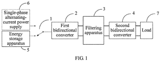
- FIG. 1 shows a block diagram of a principle of a single-phase UPS circuit according to this application.
- the UPS circuit includes a bidirectional selector switch 1, a first bidirectional converter 2, a filtering apparatus 3, a second bidirectional converter 4, and an energy storage apparatus 5, where the bidirectional selector switch 1 may be implemented by using a single-pole double-throw relay, two relays, or two bidirectional thyristors.
- a bidirectional selector switch shown in FIG. 1 is implemented by using a single-throw double-pole switch; a movable end is connected to the alternating-current end of the first bidirectional converter 2, a first fixed end is connected to the alternating-current power supply 6, a second fixed end is connected to the energy storage apparatus, and a control end is connected to a first output end of a controller; an action of the movable end is controlled by using a control signal output by the controller (not shown in the figure), thereby implementing that the alternating-current power supply 6 or the energy storage apparatus 5 is connected to the UPS circuit.
- the alternating-current power supply may be a single-phase alternating-current power supply, a two-phase alternating-current power supply, or a three-phase alternating-current power supply, where the two-phase alternating-current power supply may be an independent two-phase alternating-current power supply, or may also be in a state that an alternating current in two phases in the three-phase alternating-current power supply supplies power and the other phase is abnormal.
- a direct-current end of the first bidirectional converter 2 is connected to two ends of the filtering apparatus 3, a control end is connected to a second output end set of the controller, and an operating status of the first bidirectional converter is controlled by using a control signal output by the controller.
- the first bidirectional converter has four operating statuses, which are rectifying, inverting, boosting, and bucking.
- a direct-current end of the second bidirectional converter 4 is connected to two ends of the filtering apparatus 3, an alternating-current end is connected to a load 7, and a control end is connected to a third output end set of the controller; an operating status of the second bidirectional converter is controlled by using a control signal output by the controller; and the second bidirectional converter 4 has two operating statuses, which are rectifying and inverting.
- the filtering apparatus 3 is implemented by using a capacitor, which is mainly used to filter out an interference signal, and further used for short-time energy storage; when the alternating-current power supply and the energy storage apparatus are switched, there is a transient interruption time during the switching; in this case, power is supplied to the load by using the filtering apparatus for a short time.
- a backflow process of an alternating current when a load connected to the UPS circuit has an energy backfeed characteristic, the load is used as an energy source, an alternating current network side is the load, after energy at a load side is rectified by using the second bidirectional converter, the direct-current voltages, that is, the +bus voltage and the -bus voltage, are generated at the two ends of the filtering apparatus 3; after the +bus voltage and the -bus voltage are inverted by using the first bidirectional converter, the alternating current is obtained and provided for an alternating current network, thereby implementing that energy flows from the load side to the alternating current network side, and improving an energy utilization rate.
- the energy storage apparatus supplies power; after a direct current output by the energy storage apparatus is boosted by using the first bidirectional converter, the direct-current voltages, that is, the +bus voltage and the -bus voltage, are obtained at the two ends of the filtering apparatus 3; after the +bus voltage and the -bus voltage are inverted by using the second bidirectional converter, the alternating current is obtained and provided for the load 7.
- buses +BUS and -BUS at two ends of the energy storage apparatus are used as energy sources, that is, the direct-current voltages, that is, the +bus voltage and the -bus voltage, are obtained at the two ends of the filtering apparatus 3; after the +bus voltage and the -bus voltage are bucked by using the first bidirectional converter 2, a battery is charged, and comparing charging power with that of an existing UPS circuit added with an extra charger circuit, the charging power is higher, and a charging capability matches with main power of the alternating-current power supply.
- Energy on the buses +BUS and -BUS may be provided by the alternating-current power supply by using the first bidirectional converter, or may further be obtained from the load by the second bidirectional converter; in this case, the load needs to have an energy backfeed characteristic, that is, the load can reversely supply the energy to the second bidirectional converter.
- a process of switching between different operating statuses of the first bidirectional converter and the second bidirectional converter is controlled by the control signal output by the controller; and an operating status of the bidirectional converter is finally changed by changing an operating status of switching tubes in the first bidirectional converter and the second bidirectional converter.
- both the first bidirectional converter and the second bidirectional converter adopted have a function of allowing energy to flow in a bidirectional manner, and the alternating-current power supply and the energy storage apparatus are alternatively connected to a same bidirectional converter by using a bidirectional selector switch, so that the alternating-current power supply or the energy storage apparatus is connected to the bidirectional converter, implementing that the alternating-current power supply and the energy storage apparatus share one bidirectional converter, and no extra charger needs to be added, thereby simplifying a circuit structure of the UPS circuit.
- FIG. 2 shows a schematic structural diagram of a three-phase UPS circuit according to an embodiment of this application.
- the three-phase UPS circuit includes three single-phase UPS circuits shown in FIG. 1 , and specifically includes: a first bidirectional selector switch 21, a second bidirectional selector switch 22, a third bidirectional selector switch 23, a first bidirectional converter 24, a second bidirectional converter 25, a third bidirectional converter 26, a fourth bidirectional converter 27, a fifth bidirectional converter 28, a sixth bidirectional converter 29, an energy storage apparatus 30, and a filtering apparatus 210.
- the first bidirectional selector switch 21, the second bidirectional selector switch 22, and the third bidirectional selector switch 23 may be specifically implemented by using a single-pole double-throw relay, two independent relays, or two independent bidirectional thyristors; a single-pole double-throw is used as a bidirectional selector switch in FIG. 2 , and an on-off state of the bidirectional selector switch may be controlled by using a control signal output by a controller under the principle of a structure of a single pole double throw relay.
- a first fixed end of the first bidirectional selector switch 21 is connected to a phase A of an alternating-current power supply (a power grid), a second fixed end is connected to the energy storage apparatus 30, and a movable end is connected to an alternating-current end of the first bidirectional converter 24, where:
- Direct-current ends of the first bidirectional converter 24, the second bidirectional converter 25, the third bidirectional converter 26, the fourth bidirectional converter 27, the fifth bidirectional converter 28, and the sixth bidirectional converter 29 are all connected to two ends of the filtering apparatus 210 in parallel.
- Alternating-current ends of the fourth bidirectional converter 27, the fifth bidirectional converter 28, and the sixth bidirectional converter 29 are all connected to a load 211.
- the first bidirectional converter 24, the second bidirectional converter 25, and the third bidirectional converter 26 in this embodiment are first-type bidirectional converters, and such type of bidirectional converters have four operating statuses, which are rectifying, inverting, boosting, and bucking.
- the fourth bidirectional converter 27, the fifth bidirectional converter 28, and the sixth bidirectional converter 29 are second-type bidirectional converters, which have two operating statuses, which are inverting and rectifying.
- the first-type bidirectional converter and the second-type bidirectional converter may both be implemented by using a half-bridge fully-controlled converter, a T-type three-level converter, and an I-type three-level converter; moreover, a control manner of inverting and rectifying functions of the first-type bidirectional converter is the same as a control manner of inverting and rectifying functions of the second-type bidirectional converter.
- the controller outputs a pulse control signal with different duty cycles to control a turn-on time of a switching tube in the bidirectional converter, and the boosting and bucking functions of the bidirectional converter are finally implemented.
- the three-phase circuit uses a bidirectional selector switch to alternatively connect the alternating-current power supply and the energy storage apparatus to the UPS circuit, and can independently control close and turn-off states of three bidirectional selector switches on the three-phase circuit, that is, the three-phase circuit can independently control operation modes of three circuits, which are a phase-A circuit, a phase-B circuit, and a phase-C circuit, that is, the operation modes of the three circuits, which are the phase-A circuit, the phase-B circuit, and the phase-C circuit, can be combined arbitrarily.
- the operation modes include: a mode in which an alternating-current power supply supplies power, a mode in which an energy storage apparatus supplies power, and a mode in which a part of phases of an alternating-current power supply supply power and a remaining phase charges an energy storage apparatus.
- This embodiment mainly introduces a part before a BUS bus in detail, and an operating process of a down-level second-type bidirectional converter is exactly the same as the operating principle of the second bidirectional converter in the embodiment corresponding to FIG. 1 , which is not introduced herein in detail again.
- Any bidirectional selector switch in any one of the foregoing embodiments may be implemented by using a single-pole double-throw relay, two independent single-throw relays, or two independent bidirectional thyristors.
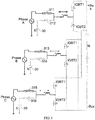
- FIG. 3 For a specific schematic diagram in which a bidirectional selector switch is implemented by using two independent single-throw relays, refer to FIG. 3 to FIG. 5 .
- FIG. 3 descriptions are made by using a first relay and a second relay that are connected to the phase-A circuit as an example, a connection relationship between relays in other phases is the same as a connection relationship between relays of the phase-A circuit, which is not described herein again.
- a first normally opened contact of a first relay 311 is connected to the phase-A alternating-current power supply, a second normally opened contact is connected to an alternating-current end of the first bidirectional converter, a coil is connected to the controller, the controller controls closing and opening of a normally opened contact of the first relay by controlling whether the coil obtains power or not, thereby controlling a type of a power supply connected to the phase-A circuit, the alternating-current power supply, or the energy storage apparatus.
- a first normally opened contact of a second relay 312 is connected to the energy storage apparatus, a second normally opened contact is connected to an alternating-current end of a first bidirectional converter, and a coil is connected to the controller.
- FIG. 6 shows a partial schematic structural diagram of another three-phase UPS circuit according to an embodiment of this application.
- a bidirectional selector switch is implemented by a bidirectional thyristor, and a phase-A circuit, a phase-B circuit, and a phase-C circuit all include two bidirectional thyristors, where one bidirectional thyristor is connected to an alternating-current power supply, and the other bidirectional thyristor is connected to an energy storage apparatus, so as to implement that the alternating-current power supply and the energy storage apparatus are alternatively connected to the UPS circuit.
- Descriptions are made by using the phase-A circuit as an example in the following, and the phase-B circuit and the phase-C circuits are the same as the phase-A circuit, which are not described herein again.
- a first end of a first bidirectional thyristor SCR1 is connected to a phase-A alternating-current power supply, a second end is connected to an alternating-current end of a first bidirectional converter, a control end is connected to a controller, and turn-on or turn-off of the first bidirectional thyristor is controlled by a control signal output by the controller.
- a first end of a second bidirectional thyristor SCR2 is connected to a phase-B alternating-current power supply, a second end is connected to an alternating-current end of a second bidirectional converter, and a control end is connected to the controller.
- the bidirectional converter in this embodiment is specifically implemented by using a half-bridge fully-controlled converter.
- the half-bridge fully-controlled converter includes a first switching tube Q1 and a second switching tube Q2.
- the Q1 and the Q2 are specifically N-channel MOSFETs (Metal-Oxide-Semiconductor Field-Effect Transistor, Metal-Oxide-Semiconductor Field-Effect Transistor); the Q1 and the Q2 are connected in series and then are connected to two ends of a filtering apparatus in parallel.
- a source of the Q1 is connected to a drain of the Q2; as a direct-current end of the bidirectional converter, a drain of the Q1 is connected to an anode of the filtering apparatus; as a direct-current end of the bidirectional converter, a source of the Q2 is connected to a cathode of the filtering apparatus; as an alternating-current end of the bidirectional converter, a common end of the Q1 and the Q2 is connected to the bidirectional selector switch.
- Gates of the Q1 and the Q2 are connected to different signal output ends of the controller, and the controller outputs two control signals to separately control turn-on and turn-off states of the Q1 and the Q2.
- the Q1 and the Q2 are controlled to turn on alternately, so as to implement rectifying and inverting functions, and boosting or bucking is implemented by controlling a turn-on time of a switching tube in the bidirectional converter by using a pulse control signal which is output by the controller and has different duty cycles.
- the bidirectional converter provided in this embodiment implemented by using a half-bridge fully-controlled converter, which is formed by few components, cost effective, and simple in control manner.
- FIG. 7 shows a schematic structural diagram of another three-phase UPS circuit according to an embodiment of this application.
- a bidirectional converter of the three-phase UPS circuit is implemented by using an I-type three-level converter, where the I-type three-level converter includes: a first switching tube Q1, a second switching tube Q2, a third switching tube Q3, a fourth switching tube Q4, a first diode D1, and a second diode D2.
- a Q1 to a Q4 shown in FIG. 8 are all N-channel MOSFET transistors and a diode is connected between a drain and a source of a MOSFET transistor; specifically, a cathode of the diode is connected to the drain, and an anode is connected to the source.
- the Q1, the Q2, the Q3, and the Q4 are connected in series successively. Specifically, a source of the Q1 is connected to a drain of the Q2, a source of the Q2 is connected to a drain of the Q3, and a source of the Q3 is connected to a drain of the Q4.
- a drain of the Q1 is connected to an anode of a filtering apparatus; as a direct-current end of the bidirectional converter, a source of the Q4 is connected to a cathode of the filtering apparatus; as an alternating-current end of the bidirectional converter, a common end of the Q2 and the Q3 is connected to a bidirectional selector switch.
- Gates of the Q1 to the Q4 are all connected to a controller, and control signals output by the controller separately control turn-on and turn-off states of the four tubes.
- the Q1 and the Q3 are controlled to complementarily turn on (that is, when the Q1 turns on, the Q3 turns off; when the Q1 turns off, the Q3 turns on); at the same time, the Q2 is controlled to be always in a turn-on state, and the Q4 is controlled to be always in a cut-off state;
- a cathode of the D1 is connected to a common end of the Q1 and the Q2, and an anode is connected to a neutral wire; a cathode of the D2 is connected to the neutral wire, and an anode is connected to a common end of the Q3 and the Q4.
- the three-phase UPS circuit provided in this embodiment is implemented by using the I-type three-level converter, and the I-type three-level converter has an advantage of a small switching loss of the switching tube, and is applicable to a UPS circuit with high switching frequency.
- FIG. 8 shows a schematic structural diagram of another three-phase UPS circuit according to an embodiment of this application.
- a bidirectional converter of the three-phase UPS circuit is implemented by using a T-type three-level converter, where the T-type three-level converter includes: a first switching tube Q1, a second switching tube Q2, a third switching tube Q3, and a fourth switching tube Q4.
- the Q1 to the Q4 are all N-channel MOSFET transistors and a diode is connected between a drain and a source of a MOSFET transistor; specifically, a cathode of the diode is connected to the drain, and an anode is connected to the source.
- the Q1 and the Q2 are connected in series and then are connected to two ends of a filtering apparatus in parallel. Specifically, a source of the Q1 is connected to a drain of the Q2; as a direct-current end of the bidirectional converter, a drain of the Q1 is connected to an anode of the filtering apparatus; as a direct-current end of the bidirectional converter, a source of the Q2 is connected to a cathode of the filtering apparatus; as an alternating-current end of the bidirectional converter, a common end of the Q1 and the Q2 is connected to a bidirectional selector switch; and
- Gates of the Q1 to the Q4 are all connected to a controller, and control signals output by the controller separately control turn-on and turn-off states of the four tubes. Specifically, when a voltage of an alternating-current end of the bidirectional converter is in a positive semi-cycle, the Q1 and the Q4 are controlled to complementarily turn on; at the same time, the Q3 is controlled to be always in a turn-on state, and the Q2 is controlled to be always in a cut-off state;
- the three-phase UPS circuit provided in this embodiment is implemented by using the T-type three-level converter, and a switching tube in the T-type three-level converter has a high voltage withstanding level and a low turn-on loss, so the T-type three-level converter is applicable to a UPS circuit of which switching frequency is not high.
- the switching tubes in the foregoing embodiments may all be implemented by using a bidirectional semiconductor device in other forms, such as a P-channel MOSFET transistor, an IGBT (Insulated Gate Bipolar Transistor, insulated gate bipolar transistor), and the like.
- a bidirectional semiconductor device such as a P-channel MOSFET transistor, an IGBT (Insulated Gate Bipolar Transistor, insulated gate bipolar transistor), and the like.
- this application further provides a method for controlling the uninterruptible power supply circuit
- the uninterruptible power supply circuit includes a bidirectional selector switch, a first-type bidirectional converter, a second-type bidirectional converter, an energy storage apparatus, a filtering apparatus, and a controller, where a first end of the bidirectional selector switch is connected to an alternating-current end of the first-type bidirectional converter, a second end is alternatively connected to an alternating-current power supply or the energy storage apparatus, and a control end is connected to a first end of the controller; a direct-current end of the first-type bidirectional converter is connected to the filtering apparatus, a control end is connected to a second output end set of the controller, and the first-type bidirectional converter has a function of rectifying, inverting, boosting or bucking; a direct-current end of the second-type bidirectional converter is connected to the filtering apparatus, an alternating-current end is connected to
Landscapes
- Engineering & Computer Science (AREA)
- Power Engineering (AREA)
- Business, Economics & Management (AREA)
- Emergency Management (AREA)
- Charge And Discharge Circuits For Batteries Or The Like (AREA)
- Inverter Devices (AREA)
Claims (12)
- Circuit d'alimentation sans coupure, comprenant : un commutateur bidirectionnel (1), un convertisseur bidirectionnel d'un premier type (2), un convertisseur bidirectionnel d'un second type (4), un appareil de stockage d'énergie (5), un appareil de filtrage (3) et un contrôleur, dans lequel :une première extrémité du commutateur bidirectionnel (1) est reliée à une extrémité de courant alternatif du convertisseur bidirectionnel du premier type (2), une seconde extrémité peut être reliée alternativement à une alimentation en courant alternatif (6) ou à l'appareil de stockage d'énergie (5) et une extrémité de commande est reliée à une première extrémité de sortie du contrôleur ;une extrémité de courant continu du convertisseur bidirectionnel du premier type (2) est reliée à l'appareil de filtrage (3), une extrémité de commande est reliée à un ensemble de secondes extrémités de sortie du contrôleur, et un état de fonctionnement du convertisseur bidirectionnel du premier type (2) comprend le redressement, l'inversion, l'amplification et la compensation ;une extrémité de courant continu du convertisseur bidirectionnel du second type (4) est reliée à l'appareil de filtrage (3), une extrémité de courant alternatif peut être reliée à une charge (7), une extrémité de commande est reliée à un troisième ensemble d'extrémités de sortie du contrôleur, et un état de fonctionnement du convertisseur bidirectionnel du second type (4) comprend l'inversion et le redressement ; etle contrôleur est configuré pour : lorsque l'appareil de stockage d'énergie doit être chargé, générer un signal de commande pour commander le commutateur bidirectionnel (1) pour se connecter à l'appareil de stockage d'énergie (5), générer un signal de commande pour commander le convertisseur bidirectionnel du premier type (2) pour être dans un état de compensation, et générer un signal de commande pour commander le convertisseur bidirectionnel du second type (4) pour être dans un état de redressement ; et lorsque l'appareil de stockage d'énergie (5) se décharge, délivrer le signal de commande pour commander le commutateur bidirectionnel (1) pour se connecter à l'appareil de stockage d'énergie (5), générer un signal de commande pour commander le convertisseur bidirectionnel du premier type (2) pour être dans un état d'amplification, et générer un signal de commande pour commander le convertisseur bidirectionnel du second type (4) pour être dans un état d'inversion.
- Circuit d'alimentation sans coupure selon la revendication 1, dans lequel le commutateur bidirectionnel (1) est un relais ou un thyristor bidirectionnel.
- Circuit d'alimentation sans coupure selon la revendication 2, dans lequel le commutateur bidirectionnel (1) est un relais unipolaire bidirectionnel, une première extrémité mobile du relais unipolaire bidirectionnel est reliée à l'alimentation en courant alternatif (6), une seconde extrémité mobile est reliée à l'appareil de stockage d'énergie (5), une extrémité fixe est reliée à l'extrémité de courant alternatif du convertisseur bidirectionnel du premier type (2), deux extrémités d'une bobine sont reliées au contrôleur.
- Circuit d'alimentation sans coupure selon la revendication 2, dans lequel le commutateur bidirectionnel (1) comprend un commutateur bidirectionnel du premier type (21) et un commutateur bidirectionnel du second type (22) ;
une première extrémité du commutateur bidirectionnel du premier type (21) est reliée à l'alimentation en courant alternatif (6), une seconde extrémité est reliée à l'extrémité de courant alternatif du convertisseur bidirectionnel du premier type (2, 24) et une extrémité de commande est reliée au contrôleur ; et
une première extrémité du commutateur bidirectionnel du second type (22) est reliée à l'appareil de stockage d'énergie (5, 30), une seconde extrémité est reliée à l'extrémité de courant alternatif du convertisseur bidirectionnel du premier type et une extrémité de commande est reliée au contrôleur. - Circuit d'alimentation sans coupure selon la revendication 4, dans lequel à la fois le commutateur bidirectionnel du premier type (21) et le commutateur bidirectionnel du second type (22) sont des relais unidirectionnels, un premier contact normalement ouvert du relais unidirectionnel est la première extrémité du commutateur bidirectionnel, un second contact normalement ouvert du relais unidirectionnel est la seconde extrémité du commutateur bidirectionnel, et comme extrémités de commande du commutateur bidirectionnel, deux extrémités d'une bobine du relais unidirectionnel sont reliées au contrôleur.
- Circuit d'alimentation sans coupure selon la revendication 4, dans lequel, lorsqu'à la fois le commutateur bidirectionnel du premier type (21) et le commutateur bidirectionnel du second type (22) sont des thyristors bidirectionnels, une première extrémité du thyristor bidirectionnel est la première extrémité du commutateur bidirectionnel, une seconde extrémité du thyristor bidirectionnel est la seconde extrémité du commutateur bidirectionnel, et une grille du thyristor bidirectionnel est l'extrémité de commande du commutateur bidirectionnel et est reliée au contrôleur.
- Circuit d'alimentation sans coupure selon l'une quelconque des revendications 4 à 6, dans lequel, lorsque l'alimentation en courant alternatif (6) est une alimentation en courant alternatif triphasé, le commutateur bidirectionnel du premier type (21) comprend un premier commutateur bidirectionnel, un second commutateur bidirectionnel, et un troisième commutateur bidirectionnel ; le commutateur bidirectionnel du second type (22) comprend un quatrième commutateur bidirectionnel, un cinquième commutateur bidirectionnel, et un sixième commutateur bidirectionnel ; le convertisseur bidirectionnel du premier type (24) comprend un premier convertisseur bidirectionnel, un second convertisseur bidirectionnel, et un troisième convertisseur bidirectionnel ; et le convertisseur bidirectionnel du second type (25) comprend un quatrième convertisseur bidirectionnel, un cinquième convertisseur bidirectionnel, et un sixième convertisseur bidirectionnel ;
une première extrémité du premier commutateur bidirectionnel est reliée à une extrémité de courant alternatif du premier convertisseur bidirectionnel, une seconde extrémité est reliée à une phase A de l'alimentation en courant alternatif triphasé, et une extrémité de commande est reliée au contrôleur ;
une première extrémité du second commutateur bidirectionnel est reliée à une extrémité de courant alternatif du second convertisseur bidirectionnel, une seconde extrémité est reliée à une phase B de l'alimentation en courant alternatif triphasé, et une extrémité de commande est reliée au contrôleur ;
une première extrémité du troisième commutateur bidirectionnel est reliée à une extrémité de courant alternatif du troisième convertisseur bidirectionnel, une seconde extrémité est reliée à une phase C de l'alimentation en courant alternatif triphasé, et une extrémité de commande est reliée au contrôleur ;
une première extrémité du quatrième commutateur bidirectionnel est reliée à l'extrémité de courant alternatif du premier convertisseur bidirectionnel, une seconde extrémité est reliée à l'appareil de stockage d'énergie, et une extrémité de commande est reliée au contrôleur ;
une première extrémité du cinquième commutateur bidirectionnel est reliée à l'extrémité de courant alternatif du second convertisseur bidirectionnel, une seconde extrémité est reliée à l'appareil de stockage d'énergie, et une extrémité de commande est reliée au contrôleur ;
une première extrémité du sixième commutateur bidirectionnel est reliée à l'extrémité de courant alternatif du troisième convertisseur bidirectionnel, une seconde extrémité est reliée à l'appareil de stockage d'énergie, et une extrémité de commande est reliée au contrôleur ;
des extrémités de courant continu du premier convertisseur bidirectionnel, du second convertisseur bidirectionnel, et du troisième convertisseur bidirectionnel sont toutes reliées à l'appareil de filtrage ;
des extrémités de courant continu du quatrième convertisseur bidirectionnel, du cinquième convertisseur bidirectionnel, et du sixième convertisseur bidirectionnel sont toutes reliées à l'appareil de filtrage, et des extrémités de courant alternatif sont toutes reliées à une charge ; et
le contrôleur est configuré pour commander séparément des états du commutateur bidirectionnel, du convertisseur bidirectionnel du premier type et du convertisseur bidirectionnel du second type qui sont reliés à un circuit de courant alternatif de phase A, à un circuit de courant alternatif de phase B, et à un circuit de courant alternatif de phase C, de manière à commander séparément les modes de fonctionnement du circuit de courant alternatif de phase A, du circuit de courant alternatif de phase B, et du circuit de courant alternatif de phase C, dans lequel les modes de fonctionnement comprennent un mode d'alimentation en courant alternatif, un mode dans lequel l'appareil de stockage d'énergie fournit de l'énergie, et un mode dans lequel l'appareil de stockage d'énergie est chargé. - Circuit d'alimentation sans coupure selon la revendication 1, dans lequel le convertisseur bidirectionnel du premier type (2) est un convertisseur bidirectionnel entièrement commandé en demi-pont, et le convertisseur bidirectionnel entièrement commandé en demi-pont comprend un premier tube de commutation et un second tube de commutation ;
une extrémité commune obtenue en reliant une première extrémité du premier tube de commutation et une seconde extrémité du second tube de commutation est utilisée comme extrémité de courant alternatif du convertisseur bidirectionnel du premier type ;
à la fois une seconde extrémité du premier tube de commutation et une première extrémité du second tube de commutation sont utilisées comme extrémité de courant continu du convertisseur bidirectionnel du premier type ; et
les extrémités de commande du premier tube de commutation et du second tube de commutation sont utilisées comme extrémité de commande du convertisseur bidirectionnel du premier type. - Circuit d'alimentation sans coupure selon la revendication 1, dans lequel le convertisseur bidirectionnel du premier type (2) est un convertisseur bidirectionnel à trois niveaux de type I, et le convertisseur bidirectionnel à trois niveaux de type I comprend un premier tube de commutation, un second tube de commutation, un troisième tube de commutation, un quatrième tube de commutation, une première diode, et une seconde diode ; une première extrémité du premier tube de commutation est reliée à une seconde extrémité du second tube de commutation, une première extrémité du second tube de commutation est reliée à une seconde extrémité du troisième tube de commutation, une première extrémité du troisième tube de commutation est reliée à une seconde extrémité du quatrième tube de commutation, une seconde extrémité du premier tube de commutation et une première extrémité du quatrième tube de commutation sont utilisées comme extrémité de courant continu du convertisseur bidirectionnel du premier type, une extrémité commune du second tube de commutation et du troisième tube de commutation est utilisée comme extrémité de courant alternatif du convertisseur bidirectionnel du premier type, et des extrémités de commande du premier tube de commutation, du second tube de commutation, du troisième tube de commutation, et du quatrième tube de commutation sont toutes reliées au contrôleur ; et
une anode de la première diode est reliée à une cathode de la seconde diode et est reliée à une extrémité de fil neutre de l'appareil de filtrage, et une cathode de la première diode est reliée à une extrémité commune du premier tube de commutation et du second tube de commutation ; et une anode de la seconde diode est reliée à une extrémité commune du troisième tube de commutation et du quatrième tube de commutation. - Circuit d'alimentation sans coupure selon la revendication 1, dans lequel le convertisseur bidirectionnel du premier type (2) est un convertisseur bidirectionnel de type T, et le convertisseur bidirectionnel de type T comprend un premier tube de commutation, un second tube de commutation, un troisième tube de commutation et un quatrième tube de commutation ;
une première extrémité du premier tube de commutation est reliée à une seconde extrémité du second tube de commutation, une extrémité commune du premier tube de commutation et du second tube de commutation est utilisée comme extrémité de courant alternatif du convertisseur bidirectionnel du premier type, et une seconde extrémité du premier tube de commutation et une première extrémité du second tube de commutation sont utilisées comme extrémité de courant continu du convertisseur bidirectionnel du premier type ;
une seconde extrémité du troisième tube de commutation est reliée à une première extrémité du quatrième tube de commutation, une première extrémité du troisième tube de commutation est reliée à l'extrémité commune du premier tube de commutation et du second tube de commutation, et une seconde extrémité du quatrième tube de commutation est reliée à une extrémité de fil neutre de l'appareil de filtrage ; et
des extrémités de commande du premier tube de commutation, du second tube de commutation, du troisième tube de commutation, et du quatrième tube de commutation sont toutes reliées au contrôleur. - Circuit d'alimentation sans coupure selon la revendication 9 ou 10, dans lequel le premier tube de commutation, le second tube de commutation, le troisième tube de commutation, ou le quatrième tube de commutation est un transistor bipolaire à grille isolée ou un transistor à effet de champ métal-oxyde-semiconducteur ; et
un émetteur du transistor bipolaire à grille isolée est une première extrémité, un collecteur est une seconde extrémité, et une grille est une extrémité de commande ; et une source du transistor à effet de champ métal-oxyde-semiconducteur est une première extrémité, un drain est une seconde extrémité, et une grille est une extrémité de commande. - Circuit d'alimentation sans coupure selon l'une quelconque des revendications 1 à 6 et 8 à 10, dans lequel l'appareil de filtrage (3) comprend un premier condensateur et un second condensateur, une cathode du premier condensateur est reliée à une anode du second condensateur et reliée à une extrémité de fil neutre de courant alternatif, et comme deux extrémités de l'appareil de filtrage, une anode du premier condensateur et une cathode du second condensateur sont reliées au convertisseur bidirectionnel du premier type et au convertisseur bidirectionnel du second type.
Applications Claiming Priority (2)
| Application Number | Priority Date | Filing Date | Title |
|---|---|---|---|
| CN201310282409.2A CN103368231B (zh) | 2013-07-05 | 2013-07-05 | 一种不间断电源电路 |
| PCT/CN2014/070449 WO2015000292A1 (fr) | 2013-07-05 | 2014-01-10 | Circuit d'alimentation électrique sans coupure |
Publications (3)
| Publication Number | Publication Date |
|---|---|
| EP2846436A1 EP2846436A1 (fr) | 2015-03-11 |
| EP2846436A4 EP2846436A4 (fr) | 2015-07-08 |
| EP2846436B1 true EP2846436B1 (fr) | 2016-12-28 |
Family
ID=49369001
Family Applications (1)
| Application Number | Title | Priority Date | Filing Date |
|---|---|---|---|
| EP14790477.5A Active EP2846436B1 (fr) | 2013-07-05 | 2014-01-10 | Circuit d'alimentation électrique sans coupure |
Country Status (4)
| Country | Link |
|---|---|
| US (1) | US9520718B2 (fr) |
| EP (1) | EP2846436B1 (fr) |
| CN (1) | CN103368231B (fr) |
| WO (1) | WO2015000292A1 (fr) |
Cited By (2)
| Publication number | Priority date | Publication date | Assignee | Title |
|---|---|---|---|---|
| EP3876388B1 (fr) * | 2020-03-03 | 2024-07-31 | Delta Electronics, Inc. | Procédé de fonctionnement d'un circuit de correction de facteur de puissance et procédé de fonctionnement d'un appareil d'alimentation électrique sans coupure |
| US12374891B2 (en) | 2022-02-25 | 2025-07-29 | Sponge Microgrids Inc. | System, controller, and method for predictive control of energy management for a segmented load centre |
Families Citing this family (38)
| Publication number | Priority date | Publication date | Assignee | Title |
|---|---|---|---|---|
| CN103368231B (zh) | 2013-07-05 | 2015-03-11 | 华为技术有限公司 | 一种不间断电源电路 |
| KR101582850B1 (ko) * | 2013-12-30 | 2016-01-07 | 주식회사 효성 | Hvdc 시스템의 전원 이중화 장치 및 그 제어방법 |
| CN104901410A (zh) * | 2014-03-04 | 2015-09-09 | 伊顿公司 | 一种ups电路 |
| CN105703470A (zh) * | 2014-11-28 | 2016-06-22 | 力博特公司 | 多电源供电系统和用于该多电源供电系统的方法 |
| EP3240139A4 (fr) * | 2014-12-25 | 2018-08-15 | Toshiba Mitsubishi-Electric Industrial Systems Corporation | Dispositif d'alimentation sans interruption |
| CN104852450B (zh) * | 2015-04-07 | 2017-03-01 | 佛山市柏克新能科技股份有限公司 | 一种电池组恒流恒压充电方法 |
| CN104753140A (zh) * | 2015-04-07 | 2015-07-01 | 佛山市柏克新能科技股份有限公司 | 一种双t型三电平在线式ups电源 |
| CN104901536A (zh) * | 2015-06-08 | 2015-09-09 | 南车青岛四方机车车辆股份有限公司 | 双向dc-dc升降压系统及储能系统 |
| CN105071670A (zh) * | 2015-08-13 | 2015-11-18 | 厦门科华恒盛股份有限公司 | 三相整流升压电路及其控制方法以及不间断电源 |
| CN105141153B (zh) * | 2015-08-13 | 2018-07-24 | 厦门科华恒盛股份有限公司 | 一种三相整流升压电路及其控制方法以及不间断电源 |
| SK7978Y1 (sk) * | 2015-09-21 | 2018-01-04 | Slovenska Polnohospodarska Univerzita V Nitre | Spôsob a zariadenie na napájanie jednofázovej elektrickej zásuvky pri výpadku jednej fázy alebo viacerých fáz |
| US9853455B1 (en) * | 2015-12-31 | 2017-12-26 | X Development Llc | Battery for fault handling in bidirectional power conversion systems |
| JP6883396B2 (ja) * | 2016-08-25 | 2021-06-09 | 矢崎総業株式会社 | 急速充電装置 |
| CN107785987B (zh) * | 2016-08-25 | 2023-06-09 | 伊顿制造(格拉斯哥)有限合伙莫尔日分支机构 | 在线式不间断电源 |
| CN107809131A (zh) * | 2016-09-06 | 2018-03-16 | 伊顿制造(格拉斯哥)有限合伙莫尔日分支机构 | 不间断电源 |
| US11053096B2 (en) | 2017-08-28 | 2021-07-06 | Otis Elevator Company | Automatic rescue and charging system for elevator drive |
| CN108599362A (zh) * | 2018-05-22 | 2018-09-28 | 郑州云海信息技术有限公司 | 一种不间断电源测试设备的无缝切换方法及其装置 |
| CN108551206B (zh) * | 2018-06-07 | 2023-11-24 | 杭州创乐电子科技有限公司 | 电源模块使用交流与直流电源供电的切换装置及方法 |
| US11984759B2 (en) | 2019-05-20 | 2024-05-14 | The University Of North Carolina At Charlotte | Grid ancillary service with uninterruptible power supply |
| CN110429822B (zh) * | 2019-08-07 | 2021-04-02 | 西北工业大学 | 一种t型llc谐振变换器及其控制方法 |
| CN112448594B (zh) * | 2019-08-28 | 2022-05-31 | 台达电子工业股份有限公司 | 间接式矩阵转换器及整流模块 |
| CN110995047B (zh) * | 2019-09-03 | 2022-06-07 | 山特电子(深圳)有限公司 | 多输入功率变换器及其控制方法和包括其的不间断电源 |
| CN111030458B (zh) * | 2019-10-12 | 2021-11-02 | 山特电子(深圳)有限公司 | 多输入功率变换器及其控制方法和包括其的不间断电源 |
| CN110995001B (zh) * | 2019-10-12 | 2021-08-24 | 山特电子(深圳)有限公司 | 多输入功率变换器及其控制方法和包括其的不间断电源 |
| CN113938045B (zh) * | 2020-06-28 | 2025-08-19 | 株洲中车时代电气股份有限公司 | 一种四流制辅助变流器、供电方法及系统 |
| DE102020119104B3 (de) * | 2020-07-21 | 2021-09-16 | Dr. Ing. H.C. F. Porsche Aktiengesellschaft | Gleichrichteranordnung |
| CN112039052B (zh) * | 2020-07-30 | 2022-06-07 | 科华恒盛股份有限公司 | 电源装置及其控制方法 |
| US11489455B2 (en) * | 2020-08-13 | 2022-11-01 | Entrantech Inc. | AC and persistent DC co-distritbution |
| US12328020B2 (en) | 2020-08-13 | 2025-06-10 | Entrantech Inc. | System for swappable battery module charging and discharging |
| US11777323B2 (en) | 2020-08-13 | 2023-10-03 | Entrantech Inc. | Sequential power discharge for batteries in a power system |
| US11605970B2 (en) | 2020-08-13 | 2023-03-14 | Entrantech Inc. | Persistent DC power and control switch |
| CN113162414B (zh) * | 2021-05-06 | 2022-12-20 | 天津大学 | 用于电能变换器的基本单元、电能变换器及通用功率接口 |
| US11831167B2 (en) | 2021-08-13 | 2023-11-28 | Entrantech Inc. | Persistent Dc circuit breaker |
| CN115882578A (zh) * | 2021-09-29 | 2023-03-31 | 硕天科技股份有限公司 | 不断电系统及其电源转换电路 |
| CN114327014B (zh) * | 2021-12-25 | 2024-10-18 | 深圳市锐宝智联信息有限公司 | 一种应用于工业信息安全的网络切换电路 |
| CN117792126A (zh) * | 2022-09-21 | 2024-03-29 | 维谛技术有限公司 | 一种不间断电源整流变换器及其控制方法 |
| CN118539585A (zh) * | 2023-02-22 | 2024-08-23 | 山特电子(深圳)有限公司 | 一种多输入电力变换器及包括其的不间断电源 |
| JP2024169143A (ja) * | 2023-05-25 | 2024-12-05 | 株式会社豊田自動織機 | 電力変換装置 |
Family Cites Families (15)
| Publication number | Priority date | Publication date | Assignee | Title |
|---|---|---|---|---|
| US5241217A (en) * | 1991-11-07 | 1993-08-31 | Premier Power, Inc. | UPS with input commutation between AC and DC sources of power |
| JP3618583B2 (ja) * | 1999-06-10 | 2005-02-09 | 三菱電機株式会社 | 無停電電源装置 |
| US6160722A (en) * | 1999-08-13 | 2000-12-12 | Powerware Corporation | Uninterruptible power supplies with dual-sourcing capability and methods of operation thereof |
| CN1421978A (zh) | 2001-11-22 | 2003-06-04 | 台达电子工业股份有限公司 | 三相不间断电源供应系统 |
| CN1153331C (zh) * | 2002-02-01 | 2004-06-09 | 艾默生网络能源有限公司 | 用于不间断电源的功率因数校正电路 |
| EP2025051B1 (fr) * | 2006-06-06 | 2014-12-31 | Ideal Power Inc. | Convertisseur universel de puissance |
| TWI315118B (en) * | 2006-07-12 | 2009-09-21 | Delta Electronics Inc | Method for controlling uninterruptible power supply apparatus |
| US8146714B2 (en) * | 2006-12-14 | 2012-04-03 | Otis Elevator Company | Elevator system including regenerative drive and rescue operation circuit for normal and power failure conditions |
| US7688048B2 (en) | 2007-02-21 | 2010-03-30 | American Power Conversion Corporation | 3-phase high power UPS |
| CN101572429B (zh) * | 2009-04-27 | 2012-07-04 | 艾默生网络能源有限公司 | 一种ups系统 |
| CN102427266B (zh) * | 2012-01-04 | 2014-03-19 | 广东易事特电源股份有限公司 | 一种多功能光伏ups系统及其控制方法 |
| CN102593945A (zh) * | 2012-02-20 | 2012-07-18 | 华为技术有限公司 | 一种不间断电源电路 |
| CN202713163U (zh) * | 2012-05-18 | 2013-01-30 | 深圳市健网科技有限公司 | 一种基于三相整流的双电源供电系统 |
| WO2014057298A1 (fr) * | 2012-10-11 | 2014-04-17 | American Power Conversion Corporation | Circuit et procédé pour fournir une alimentation électrique sans coupure |
| CN103368231B (zh) * | 2013-07-05 | 2015-03-11 | 华为技术有限公司 | 一种不间断电源电路 |
-
2013
- 2013-07-05 CN CN201310282409.2A patent/CN103368231B/zh active Active
-
2014
- 2014-01-10 WO PCT/CN2014/070449 patent/WO2015000292A1/fr not_active Ceased
- 2014-01-10 EP EP14790477.5A patent/EP2846436B1/fr active Active
- 2014-11-05 US US14/533,439 patent/US9520718B2/en active Active
Non-Patent Citations (1)
| Title |
|---|
| None * |
Cited By (2)
| Publication number | Priority date | Publication date | Assignee | Title |
|---|---|---|---|---|
| EP3876388B1 (fr) * | 2020-03-03 | 2024-07-31 | Delta Electronics, Inc. | Procédé de fonctionnement d'un circuit de correction de facteur de puissance et procédé de fonctionnement d'un appareil d'alimentation électrique sans coupure |
| US12374891B2 (en) | 2022-02-25 | 2025-07-29 | Sponge Microgrids Inc. | System, controller, and method for predictive control of energy management for a segmented load centre |
Also Published As
| Publication number | Publication date |
|---|---|
| WO2015000292A1 (fr) | 2015-01-08 |
| US9520718B2 (en) | 2016-12-13 |
| CN103368231B (zh) | 2015-03-11 |
| US20150054343A1 (en) | 2015-02-26 |
| EP2846436A1 (fr) | 2015-03-11 |
| EP2846436A4 (fr) | 2015-07-08 |
| CN103368231A (zh) | 2013-10-23 |
Similar Documents
| Publication | Publication Date | Title |
|---|---|---|
| EP2846436B1 (fr) | Circuit d'alimentation électrique sans coupure | |
| US7705489B2 (en) | Method and apparatus for providing uninterruptible power | |
| EP2737605B1 (fr) | Double convertisseur élévateur pour système ups | |
| CN103187876B (zh) | 一种不间断电源的dc/dc电路 | |
| EP3905509B1 (fr) | Dispositif de séparation de phase hors ligne et système d'onduleur | |
| EP2664053B1 (fr) | Procédé et appareil pour fournir une puissance sans coupure | |
| US11157430B2 (en) | DC-DC power converter with four way power conversion | |
| EP2800230B1 (fr) | Circuit continu-continu pour alimentation électrique ininterruptible | |
| CN109950969B (zh) | 一种基于光伏备用的变电站直流系统应急电源 | |
| US20220021298A1 (en) | Power factor correction circuit, power factor correction assembly and on-line uninterruptible power supply comprising same | |
| TW201530978A (zh) | 電源系統及供電方法 | |
| EP4366106B1 (fr) | Appareil de charge, pile de charge et système de charge | |
| JP2024075630A (ja) | 無瞬断電源供給制御装置及びその電源供給制御装置が適用されたupsモジュール | |
| EP4597793A1 (fr) | Alimentation électrique sans coupure et système d'alimentation électrique | |
| CN109193895A (zh) | 一种ups蓄电池的充放电电路及方法 | |
| CN201789335U (zh) | 非常规大功率不间断电源 | |
| Afshari et al. | Single-stage multiport capacitive-link universal power converter as a solid-state transformer for nanogrid and microgrid applications | |
| CN116742934A (zh) | 交直流复合辅助电源电路及光伏逆变器 | |
| EP3893388B1 (fr) | Dispositif, procédé et système permettant de résoudre une interférence de tension de mode commun | |
| KR102757956B1 (ko) | 영전압 방전회로를 갖는 배터리 충방전시스템 | |
| US20250309676A1 (en) | Power converters and uninterruptible power supplies (upss) including the same | |
| EP4472022A1 (fr) | Alimentation sans coupure, procédé de commande et système d'alimentation | |
| CN113824163B (zh) | 一种能量路由器及其控制方法 | |
| KR101083819B1 (ko) | Eco mode를 적용한 역률보상 무변압기형 고효율 충전기 인버터 장치 |
Legal Events
| Date | Code | Title | Description |
|---|---|---|---|
| PUAI | Public reference made under article 153(3) epc to a published international application that has entered the european phase |
Free format text: ORIGINAL CODE: 0009012 |
|
| 17P | Request for examination filed |
Effective date: 20141106 |
|
| AK | Designated contracting states |
Kind code of ref document: A1 Designated state(s): AL AT BE BG CH CY CZ DE DK EE ES FI FR GB GR HR HU IE IS IT LI LT LU LV MC MK MT NL NO PL PT RO RS SE SI SK SM TR |
|
| AX | Request for extension of the european patent |
Extension state: BA ME |
|
| RA4 | Supplementary search report drawn up and despatched (corrected) |
Effective date: 20150609 |
|
| RIC1 | Information provided on ipc code assigned before grant |
Ipc: H02J 7/02 20060101ALN20150602BHEP Ipc: H02J 9/06 20060101AFI20150602BHEP Ipc: H02M 7/483 20070101ALI20150602BHEP Ipc: H02M 7/497 20070101ALI20150602BHEP Ipc: H02M 1/10 20060101ALI20150602BHEP |
|
| REG | Reference to a national code |
Ref country code: DE Ref legal event code: R079 Ref document number: 602014005902 Country of ref document: DE Free format text: PREVIOUS MAIN CLASS: H02J0007000000 Ipc: H02J0009060000 |
|
| GRAP | Despatch of communication of intention to grant a patent |
Free format text: ORIGINAL CODE: EPIDOSNIGR1 |
|
| RIC1 | Information provided on ipc code assigned before grant |
Ipc: H02M 7/487 20070101ALI20160630BHEP Ipc: H02M 7/497 20070101ALI20160630BHEP Ipc: H02M 7/483 20070101ALI20160630BHEP Ipc: H02M 1/10 20060101ALI20160630BHEP Ipc: H02J 9/06 20060101AFI20160630BHEP Ipc: H02M 7/797 20060101ALI20160630BHEP Ipc: H02M 1/00 20060101ALI20160630BHEP Ipc: H02J 7/02 20060101ALN20160630BHEP Ipc: H02J 1/10 20060101ALI20160630BHEP |
|
| DAX | Request for extension of the european patent (deleted) | ||
| INTG | Intention to grant announced |
Effective date: 20160714 |
|
| GRAS | Grant fee paid |
Free format text: ORIGINAL CODE: EPIDOSNIGR3 |
|
| STAA | Information on the status of an ep patent application or granted ep patent |
Free format text: STATUS: GRANT OF PATENT IS INTENDED |
|
| GRAA | (expected) grant |
Free format text: ORIGINAL CODE: 0009210 |
|
| STAA | Information on the status of an ep patent application or granted ep patent |
Free format text: STATUS: THE PATENT HAS BEEN GRANTED |
|
| AK | Designated contracting states |
Kind code of ref document: B1 Designated state(s): AL AT BE BG CH CY CZ DE DK EE ES FI FR GB GR HR HU IE IS IT LI LT LU LV MC MK MT NL NO PL PT RO RS SE SI SK SM TR |
|
| REG | Reference to a national code |
Ref country code: GB Ref legal event code: FG4D |
|
| REG | Reference to a national code |
Ref country code: FR Ref legal event code: PLFP Year of fee payment: 4 |
|
| REG | Reference to a national code |
Ref country code: CH Ref legal event code: EP |
|
| REG | Reference to a national code |
Ref country code: AT Ref legal event code: REF Ref document number: 858038 Country of ref document: AT Kind code of ref document: T Effective date: 20170115 |
|
| REG | Reference to a national code |
Ref country code: IE Ref legal event code: FG4D |
|
| REG | Reference to a national code |
Ref country code: DE Ref legal event code: R096 Ref document number: 602014005902 Country of ref document: DE |
|
| PG25 | Lapsed in a contracting state [announced via postgrant information from national office to epo] |
Ref country code: LV Free format text: LAPSE BECAUSE OF FAILURE TO SUBMIT A TRANSLATION OF THE DESCRIPTION OR TO PAY THE FEE WITHIN THE PRESCRIBED TIME-LIMIT Effective date: 20161228 |
|
| REG | Reference to a national code |
Ref country code: NL Ref legal event code: FP |
|
| REG | Reference to a national code |
Ref country code: LT Ref legal event code: MG4D |
|
| PG25 | Lapsed in a contracting state [announced via postgrant information from national office to epo] |
Ref country code: SE Free format text: LAPSE BECAUSE OF FAILURE TO SUBMIT A TRANSLATION OF THE DESCRIPTION OR TO PAY THE FEE WITHIN THE PRESCRIBED TIME-LIMIT Effective date: 20161228 Ref country code: LT Free format text: LAPSE BECAUSE OF FAILURE TO SUBMIT A TRANSLATION OF THE DESCRIPTION OR TO PAY THE FEE WITHIN THE PRESCRIBED TIME-LIMIT Effective date: 20161228 Ref country code: NO Free format text: LAPSE BECAUSE OF FAILURE TO SUBMIT A TRANSLATION OF THE DESCRIPTION OR TO PAY THE FEE WITHIN THE PRESCRIBED TIME-LIMIT Effective date: 20170328 Ref country code: GR Free format text: LAPSE BECAUSE OF FAILURE TO SUBMIT A TRANSLATION OF THE DESCRIPTION OR TO PAY THE FEE WITHIN THE PRESCRIBED TIME-LIMIT Effective date: 20170329 |
|
| REG | Reference to a national code |
Ref country code: AT Ref legal event code: MK05 Ref document number: 858038 Country of ref document: AT Kind code of ref document: T Effective date: 20161228 |
|
| PG25 | Lapsed in a contracting state [announced via postgrant information from national office to epo] |
Ref country code: BE Free format text: LAPSE BECAUSE OF NON-PAYMENT OF DUE FEES Effective date: 20170131 Ref country code: HR Free format text: LAPSE BECAUSE OF FAILURE TO SUBMIT A TRANSLATION OF THE DESCRIPTION OR TO PAY THE FEE WITHIN THE PRESCRIBED TIME-LIMIT Effective date: 20161228 Ref country code: RS Free format text: LAPSE BECAUSE OF FAILURE TO SUBMIT A TRANSLATION OF THE DESCRIPTION OR TO PAY THE FEE WITHIN THE PRESCRIBED TIME-LIMIT Effective date: 20161228 Ref country code: FI Free format text: LAPSE BECAUSE OF FAILURE TO SUBMIT A TRANSLATION OF THE DESCRIPTION OR TO PAY THE FEE WITHIN THE PRESCRIBED TIME-LIMIT Effective date: 20161228 |
|
| PG25 | Lapsed in a contracting state [announced via postgrant information from national office to epo] |
Ref country code: EE Free format text: LAPSE BECAUSE OF FAILURE TO SUBMIT A TRANSLATION OF THE DESCRIPTION OR TO PAY THE FEE WITHIN THE PRESCRIBED TIME-LIMIT Effective date: 20161228 Ref country code: IS Free format text: LAPSE BECAUSE OF FAILURE TO SUBMIT A TRANSLATION OF THE DESCRIPTION OR TO PAY THE FEE WITHIN THE PRESCRIBED TIME-LIMIT Effective date: 20170428 Ref country code: CZ Free format text: LAPSE BECAUSE OF FAILURE TO SUBMIT A TRANSLATION OF THE DESCRIPTION OR TO PAY THE FEE WITHIN THE PRESCRIBED TIME-LIMIT Effective date: 20161228 Ref country code: RO Free format text: LAPSE BECAUSE OF FAILURE TO SUBMIT A TRANSLATION OF THE DESCRIPTION OR TO PAY THE FEE WITHIN THE PRESCRIBED TIME-LIMIT Effective date: 20161228 Ref country code: SK Free format text: LAPSE BECAUSE OF FAILURE TO SUBMIT A TRANSLATION OF THE DESCRIPTION OR TO PAY THE FEE WITHIN THE PRESCRIBED TIME-LIMIT Effective date: 20161228 |
|
| PG25 | Lapsed in a contracting state [announced via postgrant information from national office to epo] |
Ref country code: BE Free format text: LAPSE BECAUSE OF FAILURE TO SUBMIT A TRANSLATION OF THE DESCRIPTION OR TO PAY THE FEE WITHIN THE PRESCRIBED TIME-LIMIT Effective date: 20161228 Ref country code: ES Free format text: LAPSE BECAUSE OF FAILURE TO SUBMIT A TRANSLATION OF THE DESCRIPTION OR TO PAY THE FEE WITHIN THE PRESCRIBED TIME-LIMIT Effective date: 20161228 Ref country code: AT Free format text: LAPSE BECAUSE OF FAILURE TO SUBMIT A TRANSLATION OF THE DESCRIPTION OR TO PAY THE FEE WITHIN THE PRESCRIBED TIME-LIMIT Effective date: 20161228 Ref country code: SM Free format text: LAPSE BECAUSE OF FAILURE TO SUBMIT A TRANSLATION OF THE DESCRIPTION OR TO PAY THE FEE WITHIN THE PRESCRIBED TIME-LIMIT Effective date: 20161228 Ref country code: PL Free format text: LAPSE BECAUSE OF FAILURE TO SUBMIT A TRANSLATION OF THE DESCRIPTION OR TO PAY THE FEE WITHIN THE PRESCRIBED TIME-LIMIT Effective date: 20161228 Ref country code: BG Free format text: LAPSE BECAUSE OF FAILURE TO SUBMIT A TRANSLATION OF THE DESCRIPTION OR TO PAY THE FEE WITHIN THE PRESCRIBED TIME-LIMIT Effective date: 20170328 Ref country code: PT Free format text: LAPSE BECAUSE OF FAILURE TO SUBMIT A TRANSLATION OF THE DESCRIPTION OR TO PAY THE FEE WITHIN THE PRESCRIBED TIME-LIMIT Effective date: 20170428 |
|
| REG | Reference to a national code |
Ref country code: CH Ref legal event code: PL |
|
| PG25 | Lapsed in a contracting state [announced via postgrant information from national office to epo] |
Ref country code: MC Free format text: LAPSE BECAUSE OF FAILURE TO SUBMIT A TRANSLATION OF THE DESCRIPTION OR TO PAY THE FEE WITHIN THE PRESCRIBED TIME-LIMIT Effective date: 20161228 |
|
| REG | Reference to a national code |
Ref country code: DE Ref legal event code: R097 Ref document number: 602014005902 Country of ref document: DE |
|
| PG25 | Lapsed in a contracting state [announced via postgrant information from national office to epo] |
Ref country code: LI Free format text: LAPSE BECAUSE OF NON-PAYMENT OF DUE FEES Effective date: 20170131 Ref country code: CH Free format text: LAPSE BECAUSE OF NON-PAYMENT OF DUE FEES Effective date: 20170131 |
|
| REG | Reference to a national code |
Ref country code: IE Ref legal event code: MM4A |
|
| PLBE | No opposition filed within time limit |
Free format text: ORIGINAL CODE: 0009261 |
|
| STAA | Information on the status of an ep patent application or granted ep patent |
Free format text: STATUS: NO OPPOSITION FILED WITHIN TIME LIMIT |
|
| PG25 | Lapsed in a contracting state [announced via postgrant information from national office to epo] |
Ref country code: DK Free format text: LAPSE BECAUSE OF FAILURE TO SUBMIT A TRANSLATION OF THE DESCRIPTION OR TO PAY THE FEE WITHIN THE PRESCRIBED TIME-LIMIT Effective date: 20161228 Ref country code: LU Free format text: LAPSE BECAUSE OF NON-PAYMENT OF DUE FEES Effective date: 20170110 |
|
| 26N | No opposition filed |
Effective date: 20170929 |
|
| REG | Reference to a national code |
Ref country code: FR Ref legal event code: PLFP Year of fee payment: 5 |
|
| PG25 | Lapsed in a contracting state [announced via postgrant information from national office to epo] |
Ref country code: SI Free format text: LAPSE BECAUSE OF FAILURE TO SUBMIT A TRANSLATION OF THE DESCRIPTION OR TO PAY THE FEE WITHIN THE PRESCRIBED TIME-LIMIT Effective date: 20161228 Ref country code: IE Free format text: LAPSE BECAUSE OF NON-PAYMENT OF DUE FEES Effective date: 20170110 |
|
| PG25 | Lapsed in a contracting state [announced via postgrant information from national office to epo] |
Ref country code: MT Free format text: LAPSE BECAUSE OF NON-PAYMENT OF DUE FEES Effective date: 20170110 |
|
| PG25 | Lapsed in a contracting state [announced via postgrant information from national office to epo] |
Ref country code: HU Free format text: LAPSE BECAUSE OF FAILURE TO SUBMIT A TRANSLATION OF THE DESCRIPTION OR TO PAY THE FEE WITHIN THE PRESCRIBED TIME-LIMIT; INVALID AB INITIO Effective date: 20140110 |
|
| PG25 | Lapsed in a contracting state [announced via postgrant information from national office to epo] |
Ref country code: CY Free format text: LAPSE BECAUSE OF FAILURE TO SUBMIT A TRANSLATION OF THE DESCRIPTION OR TO PAY THE FEE WITHIN THE PRESCRIBED TIME-LIMIT Effective date: 20161228 |
|
| PG25 | Lapsed in a contracting state [announced via postgrant information from national office to epo] |
Ref country code: MK Free format text: LAPSE BECAUSE OF FAILURE TO SUBMIT A TRANSLATION OF THE DESCRIPTION OR TO PAY THE FEE WITHIN THE PRESCRIBED TIME-LIMIT Effective date: 20161228 |
|
| PG25 | Lapsed in a contracting state [announced via postgrant information from national office to epo] |
Ref country code: TR Free format text: LAPSE BECAUSE OF FAILURE TO SUBMIT A TRANSLATION OF THE DESCRIPTION OR TO PAY THE FEE WITHIN THE PRESCRIBED TIME-LIMIT Effective date: 20161228 |
|
| PG25 | Lapsed in a contracting state [announced via postgrant information from national office to epo] |
Ref country code: AL Free format text: LAPSE BECAUSE OF FAILURE TO SUBMIT A TRANSLATION OF THE DESCRIPTION OR TO PAY THE FEE WITHIN THE PRESCRIBED TIME-LIMIT Effective date: 20161228 |
|
| REG | Reference to a national code |
Ref country code: GB Ref legal event code: 732E Free format text: REGISTERED BETWEEN 20211111 AND 20211117 |
|
| REG | Reference to a national code |
Ref country code: DE Ref legal event code: R081 Ref document number: 602014005902 Country of ref document: DE Owner name: HUAWEI DIGITAL POWER TECHNOLOGIES CO., LTD., S, CN Free format text: FORMER OWNER: HUAWEI TECHNOLOGIES CO., LTD., SHENZHEN, GUANGDONG, CN |
|
| REG | Reference to a national code |
Ref country code: NL Ref legal event code: PD Owner name: HUAWEI DIGITAL POWER TECHNOLOGIES CO., LTD.; CN Free format text: DETAILS ASSIGNMENT: CHANGE OF OWNER(S), ASSIGNMENT; FORMER OWNER NAME: HUAWEI TECHNOLOGIES CO., LTD. Effective date: 20211122 |
|
| PGFP | Annual fee paid to national office [announced via postgrant information from national office to epo] |
Ref country code: GB Payment date: 20231130 Year of fee payment: 11 |
|
| PGFP | Annual fee paid to national office [announced via postgrant information from national office to epo] |
Ref country code: NL Payment date: 20231215 Year of fee payment: 11 Ref country code: FR Payment date: 20231212 Year of fee payment: 11 |
|
| PGFP | Annual fee paid to national office [announced via postgrant information from national office to epo] |
Ref country code: DE Payment date: 20231205 Year of fee payment: 11 |
|
| PGFP | Annual fee paid to national office [announced via postgrant information from national office to epo] |
Ref country code: IT Payment date: 20231212 Year of fee payment: 11 |
|
| P01 | Opt-out of the competence of the unified patent court (upc) registered |
Free format text: CASE NUMBER: UPC_APP_328128/2023 Effective date: 20230524 |
|
| REG | Reference to a national code |
Ref country code: DE Ref legal event code: R119 Ref document number: 602014005902 Country of ref document: DE |
|
| REG | Reference to a national code |
Ref country code: NL Ref legal event code: MM Effective date: 20250201 |
|
| GBPC | Gb: european patent ceased through non-payment of renewal fee |
Effective date: 20250110 |
|
| PG25 | Lapsed in a contracting state [announced via postgrant information from national office to epo] |
Ref country code: DE Free format text: LAPSE BECAUSE OF NON-PAYMENT OF DUE FEES Effective date: 20250801 |
|
| PG25 | Lapsed in a contracting state [announced via postgrant information from national office to epo] |
Ref country code: NL Free format text: LAPSE BECAUSE OF NON-PAYMENT OF DUE FEES Effective date: 20250201 |
|
| PG25 | Lapsed in a contracting state [announced via postgrant information from national office to epo] |
Ref country code: GB Free format text: LAPSE BECAUSE OF NON-PAYMENT OF DUE FEES Effective date: 20250110 |
|
| PG25 | Lapsed in a contracting state [announced via postgrant information from national office to epo] |
Ref country code: FR Free format text: LAPSE BECAUSE OF NON-PAYMENT OF DUE FEES Effective date: 20250131 |