EP2846530A2 - Verfahren und entsprechendes Gerät zur Korrektur von Bildfarbfehler - Google Patents
Verfahren und entsprechendes Gerät zur Korrektur von Bildfarbfehler Download PDFInfo
- Publication number
- EP2846530A2 EP2846530A2 EP14183384.8A EP14183384A EP2846530A2 EP 2846530 A2 EP2846530 A2 EP 2846530A2 EP 14183384 A EP14183384 A EP 14183384A EP 2846530 A2 EP2846530 A2 EP 2846530A2
- Authority
- EP
- European Patent Office
- Prior art keywords
- image
- corrected
- channel
- color
- bases
- Prior art date
- Legal status (The legal status is an assumption and is not a legal conclusion. Google has not performed a legal analysis and makes no representation as to the accuracy of the status listed.)
- Ceased
Links
Images


Classifications
-
- G—PHYSICS
- G06—COMPUTING OR CALCULATING; COUNTING
- G06T—IMAGE DATA PROCESSING OR GENERATION, IN GENERAL
- G06T5/00—Image enhancement or restoration
- G06T5/77—Retouching; Inpainting; Scratch removal
-
- H—ELECTRICITY
- H04—ELECTRIC COMMUNICATION TECHNIQUE
- H04N—PICTORIAL COMMUNICATION, e.g. TELEVISION
- H04N25/00—Circuitry of solid-state image sensors [SSIS]; Control thereof
- H04N25/60—Noise processing, e.g. detecting, correcting, reducing or removing noise
- H04N25/61—Noise processing, e.g. detecting, correcting, reducing or removing noise the noise originating only from the lens unit, e.g. flare, shading, vignetting or "cos4"
- H04N25/611—Correction of chromatic aberration
-
- H—ELECTRICITY
- H04—ELECTRIC COMMUNICATION TECHNIQUE
- H04N—PICTORIAL COMMUNICATION, e.g. TELEVISION
- H04N1/00—Scanning, transmission or reproduction of documents or the like, e.g. facsimile transmission; Details thereof
- H04N1/46—Colour picture communication systems
- H04N1/56—Processing of colour picture signals
- H04N1/58—Edge or detail enhancement; Noise or error suppression, e.g. colour misregistration correction
-
- G—PHYSICS
- G06—COMPUTING OR CALCULATING; COUNTING
- G06T—IMAGE DATA PROCESSING OR GENERATION, IN GENERAL
- G06T7/00—Image analysis
- G06T7/90—Determination of colour characteristics
-
- H—ELECTRICITY
- H04—ELECTRIC COMMUNICATION TECHNIQUE
- H04N—PICTORIAL COMMUNICATION, e.g. TELEVISION
- H04N23/00—Cameras or camera modules comprising electronic image sensors; Control thereof
- H04N23/80—Camera processing pipelines; Components thereof
- H04N23/84—Camera processing pipelines; Components thereof for processing colour signals
-
- G—PHYSICS
- G06—COMPUTING OR CALCULATING; COUNTING
- G06T—IMAGE DATA PROCESSING OR GENERATION, IN GENERAL
- G06T2207/00—Indexing scheme for image analysis or image enhancement
- G06T2207/10—Image acquisition modality
- G06T2207/10024—Color image
Definitions
- the invention relates to a method and associated apparatus for correcting color artifact of image, and more particularly, to a method and associated apparatus capable of adaptively synthesizing correction maps by weighted sum of predetermined bases and accordingly correcting image.
- Electronic device with integrated image system(s) for capturing still and/or motion images such as mobile phone, smart phone, wearable gadget, tablet computer, portable computer, hand-held computer, digital camera, digital camcorder, navigator, interactive toy, game console, remote conference terminal, surveillance system, etc.
- video such as mobile phone, smart phone, wearable gadget, tablet computer, portable computer, hand-held computer, digital camera, digital camcorder, navigator, interactive toy, game console, remote conference terminal, surveillance system, etc.
- CMOS sensors and tiny optical (lenses) modules are adopted to form embedded image systems.
- image system suffers color artifacts, e.g., lens color shading (or color shading in brief).
- Color shading is a well-known color artifact that exists in digital image systems, and is particularly prominent in images captured by CMOS sensors.
- an image system captures an image of a uniformly illuminated gray wall, it is expected to obtain a uniformly gray image as well.
- the captured image will show both intensity non-uniformity and color non-uniformity from the image center to image corners and edges.
- intensity non-uniformity causes a captured image to be darker at the image edges and corners than at the image center. This is owing to off-axis geometric factors in image formation, where light is attenuated toward image edges.
- color non-uniformity also exists in the captured image.
- the hue and the chroma of the image color gradually change outward from image center, but do not necessarily follow a radial symmetric pattern, nor attenuate at a constant fall-off rate.
- the artifact of such color non-uniformity is referred to as color shading. Color shading severely degrades image color quality.
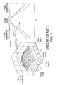
- FIG. 1 Please refer to FIG. 1 illustrating color shading of different colors.
- a green channel (a distribution of green component of each pixel) of a captured image suffers non-uniformity which falls off at edges and corners of an image, even the image is supposed to be uniform.
- FIG. 1 also includes a cross-sectional view to demonstrate non-uniformities of green, blue and red channels. It is noted that different color channels suffer different non-uniformities. Comparing to the green and blue channels, the red channel experiences a more serious fall-off toward edges.
- the overall gradual attenuation at locations away from image center is considered as vignetting or luminance falloff.
- Different fall-offs of different color channels result in color distortion in image.
- additional gains may be applied to the color channels by image signal processing (ISP) to compensate the fall-off uniformities. Since the fall-offs can be different between any two color channels at every spatial location, the correction gains should compensate fall-offs between color channels.
- ISP image signal processing
- Lens vignetting is an inherent optical property of optical lens (or lenses). Light passing through optical lens falls off from center to peripherals of lens. Theoretical analysis shows that Image irradiance decreases at a rate of cosine to the fourth power, though real lenses may not exactly follow the cosine to the fourth power law. Lens vignetting, i.e. lens fall-off effect, is a strong contributor of intensity non-uniformity.
- Pixel vignetting i.e., irradiance fall-off due to pixel structure.
- Pixel vignetting can be affected by many causes, such as pixel layout design and structure of micro-lens.
- Pixel cross-talk also contributes to color shading.
- Pixel cross-talk is a phenomenon that signal of a pixel is erroneously picked up by its adjacent pixels, normally at a different color channel.
- Pixel cross-talk may include optical cross-talk and electronic cross-talk. Their end effects are similar that signal from one color channel can leak into another color channel.
- the cross-talk may be mutual.
- IR-cut filters are used in image system.
- the effective cutoff frequency is not a constant in terms of light incident angle. There is a wavelength shift from lens center to lens peripherals. More light may be blocked at lens peripherals than at lens center, if wavelength of the light is near the IR-cut filter cutoff frequencies. As a result, red channel signal can be further attenuated at image corners and edges than green and blue channel signals.
- characteristics of color shading are sensitive to type of illuminants (light sources); to be more specifically, spectral composition of incident light. That is, when capturing images under different illuminants, the resultant images will suffer different non-uniformities, even when scenes being captured are the same. Different types of lens-sensor combinations may also cause color shading of different characteristics. Furthermore, due to manufacturing variations, characteristics of color shading are different for different units in the same batch, even under the same illuminant. Therefore, color shading correction becomes essential for the image system.
- color shading correction is achieved through complex calibration.
- the image system is exposed to a uniformly illuminated field, then images are captured under several different kinds of illuminants, so a same number of sets of fall-off maps are obtained by directly measuring non-uniformities of the captured images.
- Each set of fall-off maps corresponds to one kind of illuminant, including fall-off maps of different color channels.
- a shading correction map can be prepared to reverse non-uniformity under the corresponding kind of illuminant.
- the shading correction maps corresponding to different types of illuminants are stored in the image system.
- the conventional image system first attempts to identify which kind of ambient illuminant is currently exposed, and accordingly selects a corresponding shading correction map to correct color shading of the captured image.
- illuminant To correctly identify type of illuminant is also a challenge, because the image system for consumer electronics lacks satisfactory ability to resolve wavelength details of illuminants. Moreover, it is very difficult, if not impossible, to enumerate sufficient kinds of illuminants, since real-world illuminant mixes lights from diverse sources of different distances, different incident angles and/or different intensity, including natural radiant bodies, many kinds of man-made radiant sources, reflectors and/or scatterers.
- Incorrect illuminant identification and/or lack of proper shading correction map will cause erroneous color shading correction.
- the corrected image may become reddish in image center, because the red channel is overcompensated.
- the invention provides a low-cost effective technology to correct color shading. According to the invention, tremendous amount of efforts and cost involved in color shading calibration are saved while achieving high image quality.
- two sets of coefficients a[1] to a[N1] can be obtained to respectively generates two correction maps m1 with the same set of bases V[1] to V[N1], so as to correct the two images.
- two image systems can use their own sets of coefficients a[1] to a[N1] to respectively generates their own correction maps with the same set of the bases V[1] to V[N1], so as to correct images respectively captured by the two image systems.
- the intermediate image I is the image Isc.
- the method may further include: obtaining the intermediate image Isc by performing a feature extraction on the image Isc, such that dimensions of the image Isc and the intermediate image I may be different.
- the intermediate image I may include xi*yi pixels and the image Isc may include xs*ys pixels, and the dimensions (xi,yi) and (xs,ys) may be different.
- dimension of the image Isc may be greater than dimension of the image I, e.g., xs>xi and/or ys>yi.
- the feature extraction performed on the image Isc may include: scaling (e.g., up-scaling or down-scaling), re-sampling (e.g., up-sampling or down-sampling), and/or locally averaging (e.g., block averaging) the image Isc.
- scaling e.g., up-scaling or down-scaling
- re-sampling e.g., up-sampling or down-sampling
- locally averaging e.g., block averaging
- the method may further include: according to the correction map m1, providing an auxiliary correction map msc1, such that the auxiliary correction map msc1 may provide a correction value msc1 (x,y) for each pixel p(x,y) of the image Isc. That is, while the correction map m1 may be of dimension xi*yi to provide xi*yi correction values for the xi*yi pixels of the intermediate image I, the auxiliary correction map msc1 may be of dimension xs*ys to provide xs*ys correction values for the xs*ys pixels of the image Isc.
- the auxiliary correction map msc1 may be the correction map m1.
- the auxiliary correction map msc1 may be derived from the correction map m1 by, for example, performing interpolation on the correction map m1.
- the method of the invention may further include: calculating an auxiliary channel C1 according to color channels of the image Isc.
- the step of providing the corrected image I' may include: calculating a corrected auxiliary channel C1' according to the correction map m1 and the auxiliary channel C1, and constructing a corrected color channel c1' of the corrected image I' according to the corrected auxiliary channel C1'.
- the term "channel" of an image is used to represent a distribution capable of providing a value for each pixel p(x,y) of the image (e.g., Isc or I); for example, the auxiliary channel C1 provides a value C1 (x,y) for each pixel p(x,y) of the image Isc.
- the term "color channel" of an image is used to represent a (prime) color component distribution of the image; for example, a green color channel (or green channel in brief) of an image can describe a green component for each pixel of the image Isc.
- the color channels c0 and c0' may be of the same color, e.g., green; the color channels c1 and c1' may be of the same color, e.g., red or blue.
- the bases V[1] to V[N] used in the color ratio based embodiment may be different from the bases V[1] to V[N] used in the logarithmic color ratio based embodiment. In other words, though both the two kinds of embodiments may form the correction map by linear superposition of bases. Various embodiments may employ different bases.
- the coefficients a[1] to a[N1] are so solved that they may minimize a target function U(A1,V1,I), which receives a set of candidate coefficients ac[1] to ac[N1] (collectively denoted as a set A1), the bases V[1] to V[N1] (collectively denoted as a set V1) and the intermediate image I as inputs.
- U(A1,V1,I) receives a set of candidate coefficients ac[1] to ac[N1] (collectively denoted as a set A1), the bases V[1] to V[N1] (collectively denoted as a set V1) and the intermediate image I as inputs.
- the target function U(A1,V1,I) may include a first costfunction U1(A1,V1,I) and a second costfunction U2(A1,mA).
- the first cost function U1(A1,V1,I) is capable of indicating uniformity.
- the first cost function U1(A1,V1,I) may be formulated by a sum of weighted local terms w1(x,y)*u1(x,y;A1,V1,I) accumulated over all pixels p(x,y) of the intermediate image I.
- each local term u1(x,y;A1,V1,I) is weighted by a weighting term w1(x,y)
- the weighting term w1(x,y) is exploited to exclude, filtrate or suppress a local term u1(x,y;A1,V1,I) from the first cost function U1(A1,V1,I) if the associated pixel p(x,y) of the intermediate image I is located at regions of high spatial variation.
- the weighting term w1 (x,y) may be determined according to a gradient term G1(x,y), which may be equal to (or be calculated based on) ⁇ Ca1(x,y) ⁇ p , ⁇ ca1(x,y) ⁇ p , ⁇ ca0(x,y) ⁇ p or ⁇ L(x,y) ⁇ p , where the term L(x,y) represents luminance of the intermediate image I at pixel p(x,y).
- the weighting term w1(x,y) for the pixel p(x,y) is set to 0; if the gradient term G1(x,y) is less than the threshold, then the weighting term w1 (x,y) is set to 1. That is, the weighting term w1 (x,y) may be selectively set to two different constants 0 and 1 according to whether the gradient term G1 (x,y) is less than a threshold.
- value of the weighting term w1 (x,y) is set between 0 and 1, inclusive; for a greater gradient term G1 (x,y), the weighting term w1 (x,y) is assigned to a less value, i.e., a value closer to 0.
- the weighting terms w1(x,y) of all pixels p(x,y) are collectively referred to as a weighting map w1.
- the second cost function U2(A1,mA) may be indicative of a difference between the set A1 of the candidate coefficients ac[1] to ac[N1], and a set mA of reference coefficients ma[1] to ma[N1].
- the second cost function U2(A1,mA) may be expressed by Ld1*(A1-mA) T* Vcd * (A1-mA), wherein the term Ld1 may be a balancing coefficient; as the vector difference (A1-mA) is also an N1 by 1 column vector, the term Vcd may be an N1 by N1 positive-definite or nonnegative-definite matrix.
- the set mA may represent a priori information.
- the coefficient a0 may be constantly set equal to 1; the key issue is that the coefficient a0 for weighting the basis V[0] is not subject to optimization of the target function.
- a single auxiliary channel C1 is calculated to solve a single set of the coefficients a[1] to a[N1], so a single correction map m1, a single auxiliary correction map msc1, and a single corrected auxiliary channel C1' may be obtained to accordingly correct a single color channel c1' (e.g., a red color channel) of the corrected image I', while other color channels (e.g., blue and green color channels) of the corrected image I' may be set equal to those of the original image Isc.
- a single color channel c1' e.g., a red color channel
- other color channels e.g., blue and green color channels
- multiple auxiliary channels are calculated to respectively solve multiple sets of the coefficients, e.g., a[1] to a[N1] and b[1] to b[N2], so multiple correction maps (e.g., m1 and m2), multiple auxiliary correction maps (e.g., msc1 and msc2), as well as multiple corrected auxiliary channels (e.g., C1' and C2'), may be obtained to accordingly correct multiple color channels, e.g., c1' and c2' (such as a red color channel and a blue color channel) of the corrected image I', while rest color channel(s) of the corrected image I', if any (e.g., the green color channel), may be set equal to that (those) of the original image Isc.
- multiple correction maps e.g., m1 and m2
- auxiliary correction maps e.g., msc1 and msc2
- corrected auxiliary channels e.g
- the method may further include: calculating a second auxiliary channel C2 according to color channels of the image Isc, calculating a plurality of second coefficients b[1] to b[N2] according to the intermediate image I (or a second intermediate image obtained by performing a second feature extraction on the image Isc) and the bases V[1] to V[N2], generating a second correction map m2 by summing the bases V[1] to V[N2] respectively weighted by the associated second coefficients b[1] to b[N2], and providing the corrected image I' further according to the second correction map m2, e.g., calculating a second corrected auxiliary channel C2' according to the second correction map m2 and the second auxiliary channel C2, and constructing a second corrected color channel c2' of the corrected image I' according to the second corrected auxiliary channel C2'.
- the second auxiliary channel C2 may be defined by (c2/c0), (c0/c2), log(c2/c0) or log(c0/c2), with channel c2 being another color channel of the image I, besides the color channels c0 and c1.
- the color channels c1 and c2 may be of different colors, e.g., the color channels c1 and c2 may be different ones of a blue color channel and a red color channel of the image I.
- the quantity N2 may be equal to or different from the quantity N1 used to form the correction map m1.
- the bases V[1] to V[N2] used in the color ratio based embodiment may be different from the bases V[1] to V[N2] used in the logarithmic color ratio based embodiment (where the second auxiliary channel C2 may be defined by log(c2/c0) or log(c0/c2)).
- the second auxiliary channel C2 may be defined by log(c2/c0) or log(c0/c2)).
- both the two kinds of embodiments may form the second correction map by linear superposition of bases.
- Various embodiments may employ different bases.
- H(B1,V2,I) H1(B1,V2,I) + H2(B1,mB).
- the third cost function H1(B1,V2,I) may be formulated by a sum of weighted second local terms w2(x,y)*u2(x,y;A2,V2,I) over all pixels p(x,y) of the intermediate image I (or the second intermediate image), where a set of second candidate coefficients bc[1] to bc[N2] are collectively denoted as an input set B1, and the bases V[1] to V[N2] are collectively denoted an input set V2.
- the auxiliary channel C1 and the second auxiliary channel C2 may be defined similarly or differently; e.g., the auxiliary channel C1 may be obtained by log(c1/c0), while the auxiliary channel C2 may be obtained by (c2/c0) or (c0/c2).
- the weighting term w2(x,y) for weighting the second local terms u2(x,y;A2,V2,I) may be determined according to a second gradient term G2(x,y), which may be formulated based on ⁇ Ca2(x,y) ⁇ p , ⁇ ca2(x,y) ⁇ p or w1 (x,y), etc.
- H2(B1,mB) Ld2 * (B1-mB) T * Vcd2 * (B1-mB), wherein the term Ld2 may be a scalar balancing coefficient; as the vector difference (B2-mB) is also an N2 by 1 column vector, the term Vcd2 may be an N2 by N2 positive-definite or nonnegative-definite matrix.
- the set mB may represent a priori information.
- the image Isc may be a full still photo or a full frame of a video; alternatively, the image Isc may be a portion of a full photo or frame; after the corrected image I' is obtained, the corrected image I' is used to correct the portion of the full photo or frame.
- An objective of the invention is providing an apparatus capable of implementing the method of the invention; i.e., an apparatus for correcting color artifact of an image Isc provided by an image system.
- the apparatus including an access circuit, a correction controller and a corrector.
- the access circuit is capable of obtaining bases V[1] to V[N1].
- the correction controller is coupled to the access circuit, and capable of: calculating coefficients a[1] to a[N1] according to the image Isc (or the intermediate image I), and generating a correction map m1.
- the corrector is coupled to the correction controller, and is capable of providing a corrected image I' by correcting the image Isc according to the correction map m1.
- the correction controller is further capable of calculating an auxiliary channel C1 according to color channels of the image Isc.
- the corrector is arranged to provide the corrected image I' by calculating a corrected auxiliary channel C1' according to the correction map m1 and the auxiliary channel C1, and constructing a corrected color channel c1' of the corrected image I' according to the corrected auxiliary channel C1'.
- the correction controller is arranged to calculate the auxiliary channel C1 by dividing a predetermined color channel c1 of the image Isc by a reference color channel c0 of the image Isc; the corrector is arranged to calculate the corrected auxiliary channel C1' by multiplying the auxiliary channel C1 with an auxiliary correction map msc1 in association with the correction map m1, and to construct the corrected color channel c1' by multiplying the reference color channel c0 of the image Isc with the corrected auxiliary channel C1'.
- the correction controller is arranged to calculate the auxiliary channel C1 by a logarithm of a ratio dividing a predetermined color channel c1 of the image Isc by a reference color channel c0 of the image Isc; the corrector is arranged to calculate the corrected auxiliary channel C1' by summing the auxiliary channel C1 with the auxiliary correction map msc1, and to construct the corrected color channel c1' by multiplying the reference color channel c0 of the image Isc with an inverse logarithm of the corrected auxiliary channel C1'.
- the correction controller is further capable of: calculating second coefficients b[1] to b[N2] according to the image Isc and bases V[1] to V[N2]; generating a second correction map m2 by summing the bases V[1] to V[N2] respectively weighted by the associated second coefficients b[1] to b[N2].
- the corrector is arranged to provide the corrected image I' further according to the second correction map m2.
- the correction controller is further capable of calculating a second auxiliary channel C2 according to color channels of the image Isc.
- the corrector is arranged to provide the corrected image I' further by calculating a second corrected auxiliary channel C2' according to the second correction map m2 and the second auxiliary channel C2; as well as constructing a second corrected color channel c2' of the corrected image I' according to the second corrected auxiliary channel C2'.
- the correction controller is arranged to solve the coefficients a[1] to a[N1] by minimizing a target function U(A1,V1,I) which receives a plurality of candidate coefficients ac[1] to ac[N1] (collectively represented by a set A1), an intermediate image I associated with the image Isc, and the bases V[1] to V[N1] (collectively represented by a set V1) as inputs.
- a chrominance channel transform may be first applied to prime color channels of the image Isc, so as to generate one or more auxiliary channels (e.g., chrominance channels) suitable for compensating color shading.
- auxiliary channels e.g., chrominance channels
- color channel of an image may be used to represent a color component distribution of the image; for example, a green color channel of the image Isc may describe a green component for each pixel p(x,y) of the image Isc.
- auxiliary channel or “chrominance channel” of an image may be used to represent a distribution capable of providing a value for each pixel p(x,y) of the image; for example, an auxiliary channel C1 of the image Isc may provide a value C1(x,y) for each pixel p(x,y) of the image Isc.
- the auxiliary channel C1 may be obtained by R/B, G/B, R/G, log(R/B), log(G/B) or log(R/G) with R, G and B respectively being red, green and blue color channels of the image Isc.
- the auxiliary channel C1 may be a chrominance channel obtained by RGB-to-YUV or RGB-to-YCbCr transform, etc.
- Auxiliary (e.g., chrominance) channel(s) formed by logarithm of the ratios between two color channels, e.g., log(R/B) etc., may provide mathematical simplicities in problem formulation.
- auxiliary channel(s) defined based on ratios between two color channels, such as R/G, B/G, R/B, or their analytical forms, such as log(R/G), log(B/G), or log(R/B), etc.
- auxiliary channel(s) can be conceived and applied by persons skilled in the art without departing from the scope disclosed by the invention.
- an LCC channel set of a luminance-chrominance space of the image Isc can be obtained, where the channel L denote a luminance channel, and the two channels CC collectively represent two auxiliary channels C1 and C2.
- Color artifacts of the image Isc may be corrected via an intermediate image I.
- the intermediate image I may be the image Isc itself, or be obtained by performing a feature extraction on the image Isc, such that dimensions of the image Isc and the intermediate image I may be different.
- the intermediate image I may include xi*yi pixels and the image Isc may include xs*ys pixels, and the dimensions (xi,yi) and (xs,ys) may be different.
- dimension of the image Isc may be greater than dimension of the image I, e.g., xs>xi and/or ys>yi.
- the feature extraction performed on the image Isc may include: scaling (e.g., up-scaling or down-scaling), re-sampling (e.g., up-sampling or down-sampling), and/or locally averaging (e.g., block averaging) the image Isc.
- scaling e.g., up-scaling or down-scaling
- re-sampling e.g., up-sampling or down-sampling
- locally averaging e.g., block averaging
- every xn*yn adjacent pixels of the image Isc may be grouped as a block, so there may be (xs/xn)*(ys/yn) blocks.
- Pixel values of each block may be averaged to obtain a single pixel value of the intermediate image I.
- the dimension (xi,yi) of the intermediate image I may equal (xs/xn,ys/yn).
- a set of coefficients a[1] to a[N1] can be calculated.
- a corrected image I' may be provided by correcting the image Isc according to the correction map m1.
- the corrected image I' is provided by calculating a corrected auxiliary channel C1' according to the correction map m1 and the auxiliary channel C1 of the image I, and constructing a corrected color channel c1' of the corrected image I' according to the corrected auxiliary channel C1'.
- the bases V[1] to V[N] used in the color ratio based embodiment may be different from the bases V[1] to V[N] used in the logarithmic color ratio based embodiment. In other words, though both the two kinds of embodiments may form the correction map m1 by linear superposition of bases. Various embodiments may employ different bases.
- an auxiliary correction map msc1 may be provided, such that the auxiliary correction map msc1 is capable of providing a correction value msc1(x,y) for each pixel p(x,y) of the image Isc. That is, while the correction map m1 may be of dimension xi*yi to provide xi*yi correction values for the xi*yi pixels of the intermediate image I, the auxiliary correction map msc1 may be of dimension xs*ys to provide xs*ys correction values for the xs*ys pixels of the image Isc.
- the auxiliary correction map msc1 may be the correction map m1.
- the auxiliary correction map msc1 may be derived from the correction map m1 by, for example, performing interpolation on the correction map m1.
- the corrected image I' also has three (corrected) color channels c0', c1' and c2'.
- the color channels c1 and c1' may be of the same color, e.g., red or blue; similarly, the color channels c0 and c0' may be of the same color, e.g., green, and the color channels c2 and c2' may be of the same color, i.e., the color other than the colors of the color channels c0 and c1.
- the chrominance channel transform associating the color channels c0, c1 and/or c2 to the auxiliary channel C1 of the image Isc may also be applied to the color channels c0', c1' and c2' of the corrected image I', so as to associate the color channels c0', c1' and/or c2' to the auxiliary channel C1'. Accordingly, the corrected color channel c1' can be constructed by obtaining the corrected auxiliary channel C1'.
- the relation associating the channels c0, c1 and/or c2 to the auxiliary channel C2 of the image Isc may be exploited to define an identical relation for associating the channels c0', c1' and/or c2' to another auxiliary channel C2' of the image I'.
- color channel(s) may be transformed to auxiliary channel(s) by the chrominance channel transform
- corrected auxiliary channel(s) may be transformed back to corrected color channel(s) by an inverse transform of the chrominance channel transform.
- the corrected auxiliary channel C1' may be similarly defined by (c1'/c0').
- the corrected auxiliary channel C1' may be similarly defined by log(c1'/c0').
- the coefficients a[1] to a[N1] are so solved that they can minimize a target function U(A1,V1,I), which receives a set of candidate coefficients ac[1] to ac[N1] (collectively denoted as a set A1), the bases V[1] to V[N1] (collectively denoted as a set V1) and the intermediate image I as inputs.
- the first cost function U1(A1,V1,I) is capable of indicating uniformity over spatially smooth-varying regions of a pseudo corrected auxiliary channel Cd1', which is a corrected result of an auxiliary channel Ca1 when the candidate coefficients in the set A1 is applied.
- the chrominance channel transform which is applied to the color channel c1 of the image Isc to obtain the auxiliary channel C1, may also be applied to a color channel ca1 of the intermediate image I to obtain the auxiliary channel Ca1.
- the first cost function U1(A1,V1,I) may be formulated by a sum of weighted local terms w1(x,y)*u1(x,y;A1,V1,I) accumulated over all pixels p(x,y) of the intermediate image I.
- each local term u1(x,y;A1,V1,I) is associated with a pixel p(x,y) of the intermediate image I, and may be formulated by a q-th powered norm of a spatial gradient V of the pseudo corrected auxiliary channel Cd1' at the associated pixel p(x,y), wherein the norm ⁇ p may be a vector p-norm.
- V may be a numeric operator; for example, V ( Cd1'(x,y) ) may include an x-direction component and a y-direction component, the former involves a difference ( Cd1'(x+dx,y) - Cd1'(x,y) ) or ( Cd1'(x,y) - Cd1'(x-dx,y) ), and the latter involves a difference ( Cd1'(x,y+dy) - Cd1'(x,y ) or ( Cd1'(x,y) - Cd1'(x,y-dy) ), with dx and dy being x-direction distance and y-direction
- the weighting term w1(x,y) is exploited to exclude or suppress a local term u1(x,y;A1,V1,I) from the first cost function U1(A1,V1,I) if the associated pixel p(x,y) of the intermediate image I is located at regions of high spatial variation. Accordingly, the weighting term w1 (x,y) may be determined according to a gradient term G1 (x,y) (not shown in FIG.
- L(x,y) represents luminance of the intermediate image I at pixel p(x,y).
- the weighting term w1 (x,y) for the pixel p(x,y) is set to 0; if the gradient term G1 (x,y) is less than the threshold, then the weighting term w1(x,y) is set to 1. That is, the weighting term w1 (x,y) may be selectively set to two different constants 0 and 1 according to whether the gradient term G1(x,y) is less than a threshold.
- value of each weighting term w1 (x,y) is set between 0 and 1, inclusive; for a greater gradient term G1 (x,y), the weighting term w1(x,y) is assigned to a smaller value, i.e., a value closer to 0.
- the weighting terms w1 (x,y) of all pixels p(x,y) are collectively referred to as a weighting map w1.
- the target function U(A1 ,V1,I) may also include the second cost function U2(A1,mA) indicative of a difference between the set A1 of the candidate coefficients ac[1] to ac[N1], and a set mA of reference coefficients ma[1] to ma[N1].
- the second cost function U2(A1,mA) may be expressed by following equation eq1d.
- Ld1 may be a balancing coefficient
- Vcd may be an N1 by N1 positive-definite or nonnegative-definite matrix
- the set mA may represent a priori information; for example, while calculating a current set A(t) of the coefficients a[1] to a[N1] by equations eq1a to eq1d for a current correction map m1 (t) of a current intermediate image I(t), the set mA be an average, or weighted sum, of several preceding sets of coefficients, such as A(t-3*dt), A(t-2*dt) and A(t-1*dt) respectively utilized to obtain the correction maps m1(t-3*dt), m1(t-2*dt) and m1(t-1*dt) for elapsed intermediate images I(t-3*dt), I(t-2*dt) and I(t-1*dt).
- the second cost function U2(A1,mA) may indicate a normalized square distance of the candidate coefficients ac[1] to ac[N1] from the population mean (the set mA) as determined by color shading of preceding image(s).
- the purpose of the second cost function U2(A1,mA) is to use a priori knowledge of the distribution of the coefficients to constrain the solution (the current set A(t)), so the coefficients a[1] to a[N1] of the current set A(t), which minimize the target function U(A1,V1,I(t)) of the current intermediate image I(t), are within reasonable ranges as predicted by the a priori knowledge.
- the equation eq1a for calculating the coefficients a[1] to a[N1] to form the correction map m1 either has a closed form (analytic form) solution, or can be solved by iteration or other optimization algorithms.
- the coefficient a0 may be constantly set equal to 1; the key issue is that the coefficient a0 for weighting the basis V[0] is not subject to optimization of target function.
- the intermediate image I (as well as the bases V[.], the correction map m1, and the channels Cd1', Ca1 and ca0 to ca2 related to the equations eq1a to eq1d) may be of a smaller dimension (xi,yi), comparing to the dimension (xs,ys) of the image Isc (as well as the image I', the auxiliary correction map msc1, and the channels C1, C1' and c0 to c2).
- Such arrangement may reduce computation efforts and simplify implementation complexity for solving the coefficients a[1] to a[N1].
- the image Isc to be corrected may be transformed to a smaller intermediate image I to solve the coefficients a[1] to a[N1] and provide the correction map m1 of smaller dimension, then the smaller correction map m1 may be augmented, e.g., by interpolating the correction map m1, to a larger auxiliary correction map msc1 to correct the image Isc.
- a single auxiliary channel C1 is calculated to solve a single set of the coefficients a[1] to a[N1], so a single correction map (m1 or msc1) and a single corrected auxiliary channel C1' can be obtained to accordingly correct a single color channel c1' (e.g., a red color channel) of the corrected image I', while other color channels (e.g., blue and green color channels) of the corrected image I' may be set equal to those of the original image Isc; alternatively, the channel C2' of the image I' may be set equal to the channel C2 of the image Isc.
- a single correction map m1 or msc1
- a single corrected auxiliary channel C1' can be obtained to accordingly correct a single color channel c1' (e.g., a red color channel) of the corrected image I'
- other color channels e.g., blue and green color channels
- multiple auxiliary channels e.g., C1 and C2 are calculated to respectively solve multiple sets of the coefficients, e.g., a[1] to a[N1] and b[1] to b[N2], so multiple correction maps, e.g., m1 (or msc1) and m2 (or msc2), as well as multiple corrected auxiliary channels, e.g., C1' and C2', can be obtained to accordingly correct multiple color channels, e.g., c1' and c2' of the corrected image I', while rest color channel(s) of the corrected image I', if any (e.g., the green color channel), can be set equal to that (those) of the original image Isc.
- multiple correction maps e.g., m1 (or msc1) and m2 (or msc2)
- multiple corrected auxiliary channels e.g., C1' and C2'
- FIG. 3 illustrating a color shading correction according to an embodiment of the invention, where two correction maps m1 and m2 are calculated to correct two auxiliary channels C1 and C2 (not shown) of the original image Isc, and hence to generate two corrected auxiliary channels C1' and C2' (not shown) for constructing the corrected image I' (not shown).
- FIG. 3 further includes: calculating a plurality of second coefficients b[1] to b[N2] according to the intermediate image I (or a second intermediate image obtained by performing a second feature extraction on the image Isc) and the bases V[1] to V[N2], generating the second correction map m2 by summing the bases V[1] to V[N2] respectively weighted by the associated second coefficients b[1] to b[N2], and providing the corrected image I' further according to the second correction map m2, e.g., obtaining a second auxiliary correction map msc2 by interpolating the correction map m2, and calculating the second corrected auxiliary channel C2' according to the second correction map m2 (or the second auxiliary correction map msc2) and the second auxiliary channel C2, and constructing the second corrected color channel c2' of the corrected image I'
- the quantity N2 may be equal to or different from the quantity N1 used to form the correction map m1.
- the quantity N1 may be less than or equal to the total quantity N_total, and the quantity N2 is also less than or equal to the total quantity N_total. That is, correction maps for different auxiliary channels may by synthesized by different or identical subsets of all available bases.
- the bases V[1] to V[N2] used in the color ratio based embodiment may be different from the bases V[1] to V[N2] used in the logarithmic color ratio based embodiment (where the second auxiliary channel C2 may be defined by log(c2/c0) or log(c0/c2)).
- the second auxiliary channel C2 may be defined by log(c2/c0) or log(c0/c2)).
- both the two kinds of embodiments may form the second correction map by linear superposition of bases.
- Various embodiments may employ different bases.
- the second coefficients b[1] to b[N2] is solved to minimize a second target function H(B1,V2,I) argmin B ⁇ 1 H B ⁇ 1 , V ⁇ 2 , l
- the third cost function H1(B1,V2,I) may be formulated by a sum of weighted second local terms w2(x,y)*u2(x,y;B1,V2,I) over all pixels p(x,y) of the intermediate image I, where a set of second candidate coefficients bc[1] to bc[N2] are collectively denoted as the input set B1, and the bases V[1] to V[N2] are collectively denoted an input set V2.
- each second local term u2(x,y;B1,V2,I) is associated with a pixel of the intermediate image I, and may be formulated by a q-th powered norm of a spatial gradient V of a second pseudo corrected auxiliary channel Cd2' at the associated pixel p(x,y).
- auxiliary channels Ca1 and Ca2 may be defined similarly or differently; e.g., the auxiliary channel Ca1 may be obtained by log(ca1/ca0), while the auxiliary channel Ca2 may be obtained by (ca2/ca0) or (ca0/ca2).
- the weighting term w2(x,y) for weighting the second local terms u2(x,y;A2,V2,I) may be determined according to a second gradient term G2(x,y), which may be equal to ⁇ Ca2(x,y) ⁇ p , ⁇ ca2(x,y) ⁇ p or w1 (x,y), etc.
- the fourth cost function H2(B1 ,mB) may be formulated by following equation eq2d.
- Ld2 may be a scalar balancing coefficient
- Vcd2 may be an N2 by N2 positive-definite or nonnegative-definite matrix
- the set mB may represent a priori information; for example, while calculating a current set B(t) of the coefficients b[1] to b[N1] by equations eq2b to eq2d for a current correction map m2(t) of a current intermediate image I(t), the set mB be an average, or weighted sum, of several preceding sets of coefficients, such as B(t-3*dt), B(t-2*dt) and B(t-1*dt) respectively utilized to obtain the correction maps m2(t-3*dt), m2(t-2*dt) and m2(t-1*dt) for elapsed intermediate images I(t-3*dt), I(t-2*dt) and I(t-1*dt).
- the correction map m2 may be obtained by selecting among several candidate correction maps according to illuminant identification, or according to a property (such as norm, spatial mean, spatial variance, spatial maximum, minimum, comparison of maximum and minimum, spatially low-pass filtered result, spatially band-pass filtered result, spatially high-pass filtered result, or spatial spectrum, etc) of the correction map m1, e.g., if the property satisfies a first condition (e.g., in a first range), then a first candidate correction map is selected as the correction map m2; if the property satisfies a second condition, then a second candidate correction map is selected as the correction map m2, etc.
- a property such as norm, spatial mean, spatial variance, spatial maximum, minimum, comparison of maximum and minimum, spatially low-pass filtered result, spatially band-pass filtered result, spatially high-pass filtered result, or spatial spectrum, etc
- the correction map m2 is calculated by solving equation eq2a; if the property of the correction map m1 satisfies a second condition, then the correction map m2 is selected from one or more candidate correction map(s).
- the coefficient b0 may be constantly set equal to 1. The coefficient b0 for weighting the basis V[0] is not subject to optimization of the second target function.
- the image Isc may be a full still photo or a full frame of a video; alternatively, the image Isc may be a portion (e.g., a center portion or a user-defined portion) of a full photo or frame; after the corrected image I' is obtained, the corrected image I' is used to correct the portion of the full photo or frame.
- the (numeric) gradient operator V adopted in the local term u1(x,y;A1,V1) may be defined the same as or differently from those utilized in the weighting term w1 (x,y), in the second local term u2(x,y;A2,V2) and/or in the second weighting term w2(x,y).
- Various replacements for either one of the gradient operators may ) be: spatial variation, statistical variance, spatial difference of adjacent partitioned sub-blocks or pixels, spatial spectrum analysis of locally windowed area, etc.
- the coefficients a[1] to a[N1] for the bases V[1] to V[N1] are solved without other a priori information, except information obtained from the original image Isc and the bases V[1] to V[N1], as well as the set mA. That is, each coefficient a[n] is assumed to range from negative infinite to positive infinite.
- a priori information may be provided; for example, a predetermined range R[n] can be provided to suggest possible values of each coefficient a[n], and/or, a set of expected values of the coefficients a[1] to a[N1] can be provided as initial guess, so minimization of equation eq1a can accordingly converge faster and/or correctly (e.g., without being trapped in a local minimum).
- Each range R[n] may provide: a single finite upper bound, a single finite lower bound, or both the upper and the lower bounds for the coefficient a[n].
- the accompanying range(s) may extend from negative infinite to positive infinite.
- additional a priori information may also be provided.
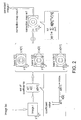
- FIG. 4 illustrating an image correction flowchart 100 according to an embodiment of the invention; using the embodiment of FIG. 2 ) as an example, main steps of the flowchart 100 may be described as follows.
- Step 102 start the flowchart 100 to correct an image Isc.
- Step 104 provide a plurality of bases V[1] to V[N1].
- Step 106 provide a target function U(A1 ,V1,I) which is to be minimized to solve a set of coefficients a[1] to a[N1].
- the target function preparation may include: obtaining an auxiliary channel Ca1 by a chrominance channel transform, and calculating a weighting map w1 for providing a weighting term w1 (x,y) (equation eq1 b) for each pixel p(x,y) of the intermediate image I.
- the weighting term w1 (x,y) for a pixel p(x,y) may be determined according to a gradient term G1(x,y), where the gradient term may be calculated based on a spatial gradient of the channel Ca1 at the pixel p(x,y) of the intermediate image I.
- the weighting term w1(x,y) is selectively set to two different constants (e.g., 1 or 0) according to whether the gradient term is less than a threshold.
- Step 108 calculate a plurality of coefficients a[1] to a[N1] by solving equation eq1a (i.e., by minimizing the target function U(A1,V1,I)), each coefficient a[n] associated with the basis V[n].
- Step 112 correct the image Isc according to the correction map m1, so as to provide a corrected image I'.
- an auxiliary correction map msc1 may be derived from the correction map m1, so a corrected auxiliary channel C1' may be calculated according to the auxiliary correction map msc1 and the channel C1.
- Step 114 end the flowchart 100.
- a single correction map m1 is obtained to provide a single corrected auxiliary channel C1' (and therefore a ) corrected color channel c1') for the corrected image I'.
- steps 106, 108 and 110 may be repeated two (or more) times to respectively provide two (or more) target functions U(A1 ,V1,I) and H(B1,V2,I) ( FIG.
- FIG. 5 illustrating an image system 200 according to an embodiment of the invention.
- the image system 200 includes an image sensor 10, a color shading corrector 20, an auto white balance module (AWB) 30, a reverse shading device 40, an image signal processor 50, an adaptive shading correction controller (ASC) 60, an optional temporal smoothing device 70, an optional multiplier 80, and an access circuit 90 for accessing a database 92.
- the corrector 20, the correction controller 60 and the access circuit 90 may form an image correction apparatus embedded in the image system 200; the apparatus is capable of implementing the embodiment shown in FIG. 2 or FIG. 3 .
- the image sensor 10 captures an input image as a raw image Isc, which is transmitted to the corrector 20 for color shading correction.
- the corrector 20 is coupled to the image sensor 10, and capable of generate a corrected image la' by correcting an intermediate image I according to a correction map m1, wherein the intermediate image I may be associated with the image Isc.
- the AWB 30 is coupled to the corrector 20, and capable of performing auto white balance on the corrected image Ia' to provide an image Iw'.
- the image signal processor 50 is coupled to the AWB 30, and capable of performing other required image processing on the image Iw' to generate an image output to be displayed on a screen (not shown).
- the reverse shading device 40 is also coupled to the AWB 30, and capable of performing reverse color shading correction on the image Iw' to restore the original intermediate image I, e.g. applying an inverse correction map on the output Iw', since the image Iw' has been color shading corrected by the corrector 20.
- the access circuit 90 is coupled to the correction controller 60, and capable of obtaining a plurality of bases V[1] to V[N1], each basis V[n] is capable of providing a basic correction value V[n](x,y) for each pixel p(x,y) of the image I.
- a nonvolatile database 92 e.g., ROM, EEPROM or flash memory
- a volatile database 92 e.g., SRAM or DRAM
- the correction controller 60 is coupled to the reverse shading device 40 and the access circuit 90, and capable of calculating coefficients a[1] to a[N1] according to the intermediate image I and the bases V[1] to V[N1], and generating the correction map m1 by summing the bases V[1] to V[N1] respectively weighted by the coefficients a[1] to a[N1].
- the bases V[1] to V[N] used in the color ratio based embodiment may be different from the bases V[1] to V[N] used in the logarithmic color ratio based embodiment. In other words, though both the two kinds of embodiments may form the correction map by linear superposition of bases. Various embodiments may employ different bases.
- the temporal smoothing device 70 is coupled to the correction controller 60, and capable of performing temporal smoothing on the correction map m1 to prevent the correction map m1 from varying too severely within a short time, since temporally rapidly varying correction map may cause flickering on the output image of the image signal processor 50.
- a current correction map generated for a current image may be averaged by weighted previous correction map(s) generated for previous image(s).
- the multiplier 80 is coupled between the correction controller 60 and the corrector 20, and capable of multiplying a luma gain on the correction map provided by the correction controller 60.
- One or both of the temporal smoothing device 70 and the multiplier 80 may be omitted.
- the temporal smoothing device 70 may implement (or support) the second (and/or the fourth) cost function U2(A1,mA) in equation eq1d (and/or H2(B1,mB) in equation eq2c).
- the correction controller 60 is further capable of calculating an auxiliary channel C1 according to color channel(s) of the image Isc, and the corrector 20 is arranged to provide the corrected image I' by: calculating a corrected auxiliary channel C1' according to the correction map m1 and the auxiliary channel C1, and constructing a corrected color channel c1' of the corrected image I' according to the corrected auxiliary channel C1'.
- the correction controller 60 is capable of calculating the auxiliary channel C1 by dividing a color channel c1 of the image Isc by another color channel c0 of the image Isc, and the corrector 20 is capable of calculating the corrected auxiliary channel C1' by multiplying the auxiliary channel C1 with the auxiliary correction map msc1, and capable of constructing the corrected color channel c1' by multiplying a color channel c0' with the corrected auxiliary channel C1'.
- the correction controller 60 is capable of calculate the auxiliary channel C1 by: taking a logarithm of a ratio dividing a color channel c1 of the image Isc by another color channel c0 of the image Isc; the corrector 20 is capable of calculating the corrected auxiliary channel C1' by summing the auxiliary channel C1 and the auxiliary correction map msc1, and capable of constructing the corrected color channel c1' by multiplying a color channel c0' with an inverse logarithm of the corrected auxiliary channel C1'.
- the image system 200 may adopt the multi-channel correction scheme exemplarily shown in FIG. 3 .
- the correction controller 60 may further be capable of: calculating other set(s) of coefficients according to the intermediate image I and the bases, e.g., an additional set of coefficients b[1] to b[N2] for the bases V[1] to V[N2], and capable of generating additional correction map(s) by summing the bases respectively weighted by the associated set(s) of coefficients, e.g., generating a correction map m2 by summing b[1]*V[1] to b[N2]*V[N2].
- the corrector 20 is capable of providing the corrected image I' according to multiple correction maps, e.g., the correction maps m1 and m2.
- the access circuit 90 is capable of reading associated bases for different set(s) of coefficients, e.g., obtaining the bases V[1] to V[N2] for the coefficients b[1] to b[N2].
- the correction controller 60 is further capable of calculating other auxiliary channel(s), e.g., an auxiliary channel C2, according to color channels of the image Isc; accordingly, the corrector 20 is capable of providing the corrected image I' by: calculating multiple corrected auxiliary channels (e.g., C1' and C2') respectively according to the associated correction maps (e.g., m1 and m2) and the auxiliary channels (e.g., C1 and C2), and constructing multiple corrected color channels (e.g., c1' and c2') of the corrected image I' according to the corrected auxiliary channels.
- multiple corrected auxiliary channels e.g., C1' and C2'
- the correction controller 60 is capable of solving the coefficients a[1] to a[N1] by minimizing a target function U(A1,V1,I) which receives a set A1 of candidate coefficients, the intermediate image I and the bases (collectively as a set V1) as inputs.
- one, some or all bases V[.] may be stored as two-dimensional matrices, while one, some or all bases V[.] may be compressed to be stored in the database 92.
- the access circuit 90 or the correction controller 60 is capable of decompressing the compressed basis (bases).
- the correction controller 60 is deposed behind AWB 30, because the correction controller 60 may leverage useful information (e.g., statistics) of the image I provided by AWB 30.
- two sets of coefficients a[1] to a[N1] can be obtained to respectively generates two correction maps m1 with the same set of bases V[1] to V[N1], so as to correct the two images respectively.
- two image systems can apply their own sets of coefficients a[1] to a[N1] to respectively generates their own correction maps with the same set of the bases V[1] to V[N1], so as to correct images respectively captured by the two image systems.
- the same set of bases (or different subsets selected from the same set of bases) may also be exploited to generate multiple correction maps for correcting multiple color channels of a same image.
- the bases V[.] may be obtained by first collecting a plurality of sample correction maps, and then applying dimension reduction on the sample correction maps.
- the sample correction maps may be experimentally calibrated correction maps obtained by measuring images captured by various units (image systems) under various illuminants. After applying the dimension reduction, a subspace spanned by a set of bases can be found, i.e., the bases can be linearly superposed to synthesize (or, within an acceptable error, approximating) any of the sample correction maps.
- the bases are therefore adopted to implement embodiments of FIG. 2 and FIG. 3 .
- the dimension reduction technique may be: discrete cosine transform, wavelet transform, principal component analysis, generalized principal component analysis, independent component analysis, or sparse representation ... etc.
- the invention can be generally applied to any image processing system where the image Isc to be corrected is received from storage medium and/or network ... etc.
- correcting color artifact of an image may include: finding a (or multiple) set of coefficients to synthesize a (or multiple) fall-off pattern of the image, accordingly calculating a (or multiple) correction map capable of compensating attenuation of the fall-off pattern, and then correct the original image.
- the invention can both enhance image quality and reduce costs of image system.
Landscapes
- Engineering & Computer Science (AREA)
- Multimedia (AREA)
- Signal Processing (AREA)
- Physics & Mathematics (AREA)
- General Physics & Mathematics (AREA)
- Theoretical Computer Science (AREA)
- Computer Vision & Pattern Recognition (AREA)
- Image Processing (AREA)
- Facsimile Image Signal Circuits (AREA)
- Color Television Image Signal Generators (AREA)
- Color Image Communication Systems (AREA)
- Apparatus For Radiation Diagnosis (AREA)
- Processing Of Color Television Signals (AREA)
Applications Claiming Priority (2)
| Application Number | Priority Date | Filing Date | Title |
|---|---|---|---|
| US201361875216P | 2013-09-09 | 2013-09-09 | |
| US14/341,870 US9443322B2 (en) | 2013-09-09 | 2014-07-28 | Method and associated apparatus for correcting color artifact of image |
Publications (2)
| Publication Number | Publication Date |
|---|---|
| EP2846530A2 true EP2846530A2 (de) | 2015-03-11 |
| EP2846530A3 EP2846530A3 (de) | 2015-04-22 |
Family
ID=51518545
Family Applications (1)
| Application Number | Title | Priority Date | Filing Date |
|---|---|---|---|
| EP20140183384 Ceased EP2846530A3 (de) | 2013-09-09 | 2014-09-03 | Verfahren und entsprechendes Gerät zur Korrektur von Bildfarbfehler |
Country Status (8)
| Country | Link |
|---|---|
| US (1) | US9443322B2 (de) |
| EP (1) | EP2846530A3 (de) |
| JP (1) | JP5859080B2 (de) |
| KR (1) | KR101663871B1 (de) |
| CN (1) | CN104424626B (de) |
| BR (1) | BR102014022192A2 (de) |
| IN (1) | IN2014MU02870A (de) |
| TW (1) | TWI557686B (de) |
Cited By (1)
| Publication number | Priority date | Publication date | Assignee | Title |
|---|---|---|---|---|
| EP3185534A1 (de) * | 2015-12-23 | 2017-06-28 | Robert Bosch Gmbh | Kameravorrichtung mit roter haloreduktion |
Families Citing this family (13)
| Publication number | Priority date | Publication date | Assignee | Title |
|---|---|---|---|---|
| TWI578787B (zh) | 2016-03-18 | 2017-04-11 | 圓展科技股份有限公司 | 具有自動白平衡功能的攝影裝置與自動白平衡的校正方法 |
| CN108204979B (zh) * | 2016-12-19 | 2020-10-27 | 网易(杭州)网络有限公司 | 用于试纸检测设备中光源校准的方法和装置 |
| US10286688B2 (en) | 2017-01-25 | 2019-05-14 | Ricoh Company, Ltd. | Liquid discharge apparatus, liquid curing method, and computer program product |
| CN106910224B (zh) * | 2017-02-27 | 2019-11-22 | 清华大学 | 宽视场高分辨显微成像中像感器阵列标定方法 |
| CN107564047B (zh) * | 2017-09-12 | 2020-10-20 | 北京小米移动软件有限公司 | 图像处理方法及装置、电子设备和计算机可读存储介质 |
| CN109788261B (zh) * | 2017-11-15 | 2021-06-22 | 瑞昱半导体股份有限公司 | 颜色偏移校正方法及装置 |
| TWI638336B (zh) * | 2017-11-22 | 2018-10-11 | 瑞昱半導體股份有限公司 | 影像增強方法及影像增強裝置 |
| DE102018115991B4 (de) * | 2018-07-02 | 2023-12-07 | Basler Ag | Digitale schaltung zur korrektur eines vignettierungseffekts in werten von pixeln eines bildes einer elektronischen kamera |
| CN110910822B (zh) * | 2019-11-27 | 2021-03-16 | 深圳市华星光电半导体显示技术有限公司 | 一种oled补偿方法、补偿装置及计算机可读存储介质 |
| US11475594B1 (en) * | 2019-12-03 | 2022-10-18 | Gopro, Inc. | Systems and methods for dynamic optical element detection |
| CN111429534B (zh) * | 2020-02-17 | 2020-11-13 | 深圳市六六六国际旅行社有限公司 | 一种图像偏色矫正方法及装置 |
| CN112365555A (zh) * | 2020-10-26 | 2021-02-12 | 北京计算机技术及应用研究所 | 基于组稀疏正则化的全变分高能闪光照相密度反演方法 |
| TWI792454B (zh) | 2021-07-28 | 2023-02-11 | 瑞昱半導體股份有限公司 | 自適應的圖像陰影校正方法及圖像陰影校正系統 |
Family Cites Families (22)
| Publication number | Priority date | Publication date | Assignee | Title |
|---|---|---|---|---|
| JPH07307877A (ja) * | 1994-05-13 | 1995-11-21 | Mitsubishi Electric Corp | 赤外線撮像装置 |
| US5818525A (en) | 1996-06-17 | 1998-10-06 | Loral Fairchild Corp. | RGB image correction using compressed flat illuminated files and a simple one or two point correction algorithm |
| TWI318536B (en) * | 2006-09-29 | 2009-12-11 | Sony Taiwan Ltd | A method of color matching applied on the image apparatus |
| US8055070B2 (en) * | 2007-01-05 | 2011-11-08 | Geo Semiconductor Inc. | Color and geometry distortion correction system and method |
| JP2008177794A (ja) | 2007-01-17 | 2008-07-31 | Sharp Corp | 撮像装置の色シェーディング補正装置、撮像装置および撮像装置の色シェーディング補正方法 |
| JP2008277926A (ja) | 2007-04-25 | 2008-11-13 | Kyocera Corp | 画像データ処理方法と該方法を用いた撮像装置 |
| JP2009088800A (ja) | 2007-09-28 | 2009-04-23 | Nikon Corp | カラー撮像装置 |
| US20090091660A1 (en) * | 2007-10-08 | 2009-04-09 | Yu-Wei Wang | Method and apparatus for processing color components of pixel through adding white light adaptively |
| US8229215B2 (en) * | 2007-12-03 | 2012-07-24 | Omnivision Technologies, Inc. | Image sensor apparatus and method for scene illuminant estimation |
| EP2101207A1 (de) * | 2008-03-12 | 2009-09-16 | Deutsche Thomson OHG | Verfahren zur Korrektur von Farbfehlern |
| JP2010103642A (ja) * | 2008-10-21 | 2010-05-06 | Toshiba Corp | シェーディング補正装置 |
| US8876290B2 (en) * | 2009-07-06 | 2014-11-04 | Wavetec Vision Systems, Inc. | Objective quality metric for ocular wavefront measurements |
| EP2484119A4 (de) * | 2009-09-29 | 2013-10-30 | Hewlett Packard Development Co | Weissabgleichkorrektur bei einem aufgenommenen digitalbild |
| TWI377044B (en) | 2009-11-06 | 2012-11-21 | Nat Univ Chung Cheng | Method for reconstructing color images |
| JP5528173B2 (ja) * | 2010-03-31 | 2014-06-25 | キヤノン株式会社 | 画像処理装置、撮像装置および画像処理プログラム |
| TW201305965A (zh) * | 2011-07-18 | 2013-02-01 | Novatek Microelectronics Corp | 影像處理方法 |
| JP5681589B2 (ja) | 2011-08-18 | 2015-03-11 | 富士フイルム株式会社 | 撮像装置及び画像処理方法 |
| JP5234150B2 (ja) | 2011-08-26 | 2013-07-10 | カシオ計算機株式会社 | 画像処理装置、画像処理方法及びプログラム |
| JP5868076B2 (ja) * | 2011-08-31 | 2016-02-24 | キヤノン株式会社 | 画像処理装置及び画像処理方法 |
| JP2013118598A (ja) * | 2011-12-05 | 2013-06-13 | Canon Inc | 撮像装置のシェーディング補正方法、及び撮像装置 |
| JP5911296B2 (ja) * | 2011-12-22 | 2016-04-27 | オリンパス株式会社 | 画像処理装置、撮像装置、顕微鏡システム、画像処理方法、及び画像処理プログラム |
| CN102867295B (zh) * | 2012-08-06 | 2015-10-21 | 电子科技大学 | 一种彩色图像颜色校正方法 |
-
2014
- 2014-07-28 US US14/341,870 patent/US9443322B2/en active Active
- 2014-09-03 EP EP20140183384 patent/EP2846530A3/de not_active Ceased
- 2014-09-05 JP JP2014181353A patent/JP5859080B2/ja not_active Expired - Fee Related
- 2014-09-05 KR KR1020140119276A patent/KR101663871B1/ko not_active Expired - Fee Related
- 2014-09-08 BR BR102014022192A patent/BR102014022192A2/pt not_active IP Right Cessation
- 2014-09-09 IN IN2870MU2014 patent/IN2014MU02870A/en unknown
- 2014-09-09 CN CN201410455321.0A patent/CN104424626B/zh not_active Expired - Fee Related
- 2014-09-09 TW TW103130951A patent/TWI557686B/zh not_active IP Right Cessation
Non-Patent Citations (1)
| Title |
|---|
| None |
Cited By (2)
| Publication number | Priority date | Publication date | Assignee | Title |
|---|---|---|---|---|
| EP3185534A1 (de) * | 2015-12-23 | 2017-06-28 | Robert Bosch Gmbh | Kameravorrichtung mit roter haloreduktion |
| US10158791B2 (en) | 2015-12-23 | 2018-12-18 | Robert Bosch Gmbh | Camera device with red halo reduction |
Also Published As
| Publication number | Publication date |
|---|---|
| TW201523515A (zh) | 2015-06-16 |
| KR101663871B1 (ko) | 2016-10-07 |
| BR102014022192A2 (pt) | 2015-12-01 |
| KR20150029590A (ko) | 2015-03-18 |
| US9443322B2 (en) | 2016-09-13 |
| EP2846530A3 (de) | 2015-04-22 |
| JP5859080B2 (ja) | 2016-02-10 |
| US20150071535A1 (en) | 2015-03-12 |
| TWI557686B (zh) | 2016-11-11 |
| CN104424626A (zh) | 2015-03-18 |
| JP2015053057A (ja) | 2015-03-19 |
| CN104424626B (zh) | 2017-07-21 |
| IN2014MU02870A (de) | 2015-10-09 |
Similar Documents
| Publication | Publication Date | Title |
|---|---|---|
| US9443322B2 (en) | Method and associated apparatus for correcting color artifact of image | |
| US12243190B2 (en) | Systems and methods for synthesizing high resolution images using images captured by an array of independently controllable imagers | |
| US11849224B2 (en) | Global tone mapping | |
| US10136107B2 (en) | Imaging systems with visible light sensitive pixels and infrared light sensitive pixels | |
| EP3054675B1 (de) | Abbildungssysteme mit durchsichtigen filterpixeln | |
| US8131097B2 (en) | Method and apparatus for extended depth-of-field image restoration | |
| US8115825B2 (en) | Electronic device with two image sensors | |
| CN111226256A (zh) | 用于图像动态范围调整的系统和方法 | |
| US20150146038A1 (en) | Apparatus, systems, and methods for adaptive image processing | |
| US8089534B2 (en) | Multi illuminant shading correction using singular value decomposition | |
| TWI617198B (zh) | 具有透明濾波器像素之成像系統 | |
| TWI536765B (zh) | 具有透明濾波器像素之成像系統 | |
| Lai | Systems and Autonomous Driving | |
| TWI601427B (zh) | 具有透明濾波器像素之成像系統 | |
| HK1255655A1 (en) | Imaging systems with clear filter pixels | |
| Whitehead et al. | A low complexity method of color image demosaicing directly to YCbCr 4: 2: 0 | |
| HK1222962B (en) | Imaging systems with clear filter pixels |
Legal Events
| Date | Code | Title | Description |
|---|---|---|---|
| 17P | Request for examination filed |
Effective date: 20140903 |
|
| AK | Designated contracting states |
Kind code of ref document: A2 Designated state(s): AL AT BE BG CH CY CZ DE DK EE ES FI FR GB GR HR HU IE IS IT LI LT LU LV MC MK MT NL NO PL PT RO RS SE SI SK SM TR |
|
| AX | Request for extension of the european patent |
Extension state: BA ME |
|
| PUAI | Public reference made under article 153(3) epc to a published international application that has entered the european phase |
Free format text: ORIGINAL CODE: 0009012 |
|
| PUAL | Search report despatched |
Free format text: ORIGINAL CODE: 0009013 |
|
| AK | Designated contracting states |
Kind code of ref document: A3 Designated state(s): AL AT BE BG CH CY CZ DE DK EE ES FI FR GB GR HR HU IE IS IT LI LT LU LV MC MK MT NL NO PL PT RO RS SE SI SK SM TR |
|
| AX | Request for extension of the european patent |
Extension state: BA ME |
|
| RIC1 | Information provided on ipc code assigned before grant |
Ipc: H04N 1/58 20060101AFI20150316BHEP |
|
| R17P | Request for examination filed (corrected) |
Effective date: 20150813 |
|
| RBV | Designated contracting states (corrected) |
Designated state(s): AL AT BE BG CH CY CZ DE DK EE ES FI FR GB GR HR HU IE IS IT LI LT LU LV MC MK MT NL NO PL PT RO RS SE SI SK SM TR |
|
| 17Q | First examination report despatched |
Effective date: 20171004 |
|
| STAA | Information on the status of an ep patent application or granted ep patent |
Free format text: STATUS: THE APPLICATION HAS BEEN REFUSED |
|
| 18R | Application refused |
Effective date: 20181126 |