EP2847401B1 - Serrure - Google Patents
Serrure Download PDFInfo
- Publication number
- EP2847401B1 EP2847401B1 EP13788401.1A EP13788401A EP2847401B1 EP 2847401 B1 EP2847401 B1 EP 2847401B1 EP 13788401 A EP13788401 A EP 13788401A EP 2847401 B1 EP2847401 B1 EP 2847401B1
- Authority
- EP
- European Patent Office
- Prior art keywords
- pin
- motor
- linkage
- shaft
- lock
- Prior art date
- Legal status (The legal status is an assumption and is not a legal conclusion. Google has not performed a legal analysis and makes no representation as to the accuracy of the status listed.)
- Active
Links
Images




Classifications
-
- E—FIXED CONSTRUCTIONS
- E05—LOCKS; KEYS; WINDOW OR DOOR FITTINGS; SAFES
- E05B—LOCKS; ACCESSORIES THEREFOR; HANDCUFFS
- E05B63/00—Locks or fastenings with special structural characteristics
- E05B63/08—Mortise locks
-
- E—FIXED CONSTRUCTIONS
- E05—LOCKS; KEYS; WINDOW OR DOOR FITTINGS; SAFES
- E05B—LOCKS; ACCESSORIES THEREFOR; HANDCUFFS
- E05B63/00—Locks or fastenings with special structural characteristics
- E05B63/14—Arrangement of several locks or locks with several bolts, e.g. arranged one behind the other
-
- E—FIXED CONSTRUCTIONS
- E05—LOCKS; KEYS; WINDOW OR DOOR FITTINGS; SAFES
- E05B—LOCKS; ACCESSORIES THEREFOR; HANDCUFFS
- E05B15/00—Other details of locks; Parts for engagement by bolts of fastening devices
- E05B15/02—Striking-plates; Keepers; Bolt staples; Escutcheons
- E05B15/0205—Striking-plates, keepers, staples
- E05B15/022—Striking-plates, keepers, staples movable, resilient or yieldable
-
- E—FIXED CONSTRUCTIONS
- E05—LOCKS; KEYS; WINDOW OR DOOR FITTINGS; SAFES
- E05B—LOCKS; ACCESSORIES THEREFOR; HANDCUFFS
- E05B17/00—Accessories in connection with locks
- E05B17/007—Devices for reducing friction between lock parts
-
- E—FIXED CONSTRUCTIONS
- E05—LOCKS; KEYS; WINDOW OR DOOR FITTINGS; SAFES
- E05B—LOCKS; ACCESSORIES THEREFOR; HANDCUFFS
- E05B47/00—Operating or controlling locks or other fastening devices by electric or magnetic means
- E05B47/0001—Operating or controlling locks or other fastening devices by electric or magnetic means with electric actuators; Constructional features thereof
- E05B47/0012—Operating or controlling locks or other fastening devices by electric or magnetic means with electric actuators; Constructional features thereof with rotary electromotors
-
- E—FIXED CONSTRUCTIONS
- E05—LOCKS; KEYS; WINDOW OR DOOR FITTINGS; SAFES
- E05B—LOCKS; ACCESSORIES THEREFOR; HANDCUFFS
- E05B47/00—Operating or controlling locks or other fastening devices by electric or magnetic means
- E05B47/02—Movement of the bolt by electromagnetic means; Adaptation of locks, latches, or parts thereof, for movement of the bolt by electromagnetic means
- E05B47/023—Movement of the bolt by electromagnetic means; Adaptation of locks, latches, or parts thereof, for movement of the bolt by electromagnetic means the bolt moving pivotally or rotatively
-
- E—FIXED CONSTRUCTIONS
- E05—LOCKS; KEYS; WINDOW OR DOOR FITTINGS; SAFES
- E05B—LOCKS; ACCESSORIES THEREFOR; HANDCUFFS
- E05B65/00—Locks or fastenings for special use
- E05B65/06—Locks or fastenings for special use for swing doors or windows, i.e. opening inwards and outwards
-
- E—FIXED CONSTRUCTIONS
- E05—LOCKS; KEYS; WINDOW OR DOOR FITTINGS; SAFES
- E05B—LOCKS; ACCESSORIES THEREFOR; HANDCUFFS
- E05B47/00—Operating or controlling locks or other fastening devices by electric or magnetic means
- E05B2047/0048—Circuits, feeding, monitoring
- E05B2047/0057—Feeding
- E05B2047/0058—Feeding by batteries
-
- E—FIXED CONSTRUCTIONS
- E05—LOCKS; KEYS; WINDOW OR DOOR FITTINGS; SAFES
- E05B—LOCKS; ACCESSORIES THEREFOR; HANDCUFFS
- E05B47/00—Operating or controlling locks or other fastening devices by electric or magnetic means
- E05B2047/0048—Circuits, feeding, monitoring
- E05B2047/0067—Monitoring
- E05B2047/0068—Door closed
-
- E—FIXED CONSTRUCTIONS
- E05—LOCKS; KEYS; WINDOW OR DOOR FITTINGS; SAFES
- E05B—LOCKS; ACCESSORIES THEREFOR; HANDCUFFS
- E05B47/00—Operating or controlling locks or other fastening devices by electric or magnetic means
- E05B2047/0072—Operation
- E05B2047/0076—Current to lock only, i.e. "fail-safe"
-
- Y—GENERAL TAGGING OF NEW TECHNOLOGICAL DEVELOPMENTS; GENERAL TAGGING OF CROSS-SECTIONAL TECHNOLOGIES SPANNING OVER SEVERAL SECTIONS OF THE IPC; TECHNICAL SUBJECTS COVERED BY FORMER USPC CROSS-REFERENCE ART COLLECTIONS [XRACs] AND DIGESTS
- Y10—TECHNICAL SUBJECTS COVERED BY FORMER USPC
- Y10T—TECHNICAL SUBJECTS COVERED BY FORMER US CLASSIFICATION
- Y10T292/00—Closure fasteners
- Y10T292/08—Bolts
- Y10T292/1043—Swinging
- Y10T292/1075—Operating means
- Y10T292/1082—Motor
Definitions
- the present invention relates to a lock for a door or other moveable member that moves between an open position and a closed position to open and close a pathway or opening, for example a window, a cupboard or a gate.
- Prior art locks for locking a door to a door frame comprises a pin or bolt that is movable between a retracted position to unlock the door from the door frame and an extended position to lock the door to the door frame.
- the pin of the lock is actuated between the retracted and extended positions by a key for turning a mechanism for moving the pin.
- Modern locks may comprise an actuator such as an electric motor for moving the pin between the retracted and extended positions.
- Such locks may be controlled remotely by a security system.
- the retraction rate of the pin is governed by the speed of the motor.
- the motor may move the pin at a relatively slow speed.
- the actuator and mechanism for moving the pin must have sufficient power to move the pin from the extended position to the retracted position under onerous conditions, for example when a load is applied to a door that causes a force to be applied to the pin that the lock must overcome to retract the pin to unlock the door.
- US 4,685,709 is an example of a lock comprising an electric motor for moving the locking pin between the retracted and extended positions.
- the motor is energized in order to rotate an operating disc, to allow a latch bolt to be moved from a retracted or unlocked position to an extended or locked position under the action of a spring, to lock the door in a closed position to a door frame.
- a deadlock lever prevents the latch bolt from moving from the locked position.
- the motor is again energized to rotate the operating disc to disengage the deadlock lever and then move the latch bolt from the extended position to the retracted position against the action of the spring to unlock the door.
- a lock that comprises an electrical actuator for driving the lock pin may be configured to a fail-open mode or a fail-close mode.
- a fail-open mode when the door is closed and locked and electrical power to the lock is cut, the lock automatically retracts the pin to unlock the door.
- a fail-close mode when a door is closed unlocked and electrical power to the lock is cut, the lock automatically extends the pin to lock the door.
- a lock may be configurable to set the lock as a fail-close or fail-open lock. Configuration of such a lock may not be straight forward and may require multiple mechanical and electrical adjustments to be made.
- a lock for locking a double swing door must be capable of locking a door when the door approaches a door frame from either of two directions.
- the present invention consists in a lock for locking a door, the lock comprising:
- the intermediate position is adjacent the first position so that a relatively small motor movement is required to operate the latch to the unlatch position and move the pin to the retracted position.
- the mechanism comprises a linkage coupled to the pin, the linkage comprising:
- the linkage shaft, the first arm shaft and the second arm shaft are substantially aligned on a line substantially parallel to a plane of the door when in the closed position.
- the mechanism comprises a linkage coupled to the pin, the linkage comprising:
- the centre of the linkage shaft passes through a line extending between the centre of the first arm shaft and a centre of the second arm shaft by a small distance, the angle between the first and second arms being less than approximately 181 degrees.
- the controller being programmed to:
- the mechanism comprises a locking mechanism driven by the motor, the locking mechanism adapted to contact the linkage when the motor is driven in the forward direction to move the pin from the retracted position to the extended position.
- the locking mechanism comprises a driven member driven by the motor, the driven member adapted to contact the linkage when the motor is driven in the forward direction to move the pin from the retracted position to the extended position.
- the driven member is adapted to contact the linkage shaft, the driven member comprising a recess for receiving the linkage shaft, the recess open to a side so that the linkage shaft is released from the recess when the motor is driven in the reverse direction to disengage the motor from the pin.
- the mechanism comprises an unlocking mechanism driven by the motor, the unlocking mechanism adapted to contact the linkage when the motor is in the third position so that movement of the motor from the third position to the first position moves the linkage so that the centre of the linkage shaft passes through a line extending between the centre of the first arm shaft and a centre of the second arm shaft so that the pin moves to the retracted position under action of the spring.
- the unlocking mechanism is adapted to contact the linkage shaft.
- the unlocking mechanism comprises;
- the unlock member is a driven member driven by the motor, the driven member comprising a projection extending from the driven member and the unlock cam comprises a slot for receiving the projection, and when the motor is in the third position, the projection bears against a first end of the slot and the linkage bears against a second opposite end of the slot to couple the linkage to the motor via the unlock cam and the driven member.
- the mechanism comprises a pinion fixed to a shaft of the motor, and the driven member comprises a rack engaged with the pinion.
- the mechanism comprises a pair of spaced apart walls with the linkage located in between, each wall comprising a slot or groove for receiving the linkage shaft, ends of the slots or groove defining end stops for movement of the linkage.
- the mechanism comprises a second spring for biasing the latch to the latched position.
- the latch comprises a latch arm for contacting the linkage to retain the pin in the extended position, the latch arm pivotally mounted on a latch shaft to move between the latched and unlatched positions.
- the mechanism comprises a latch trigger driven by the motor for moving the latch between the latched and unlatched positions.
- the latch comprises a link arm pivotally connected to the latch arm and the latch trigger is a driven member driven by the motor and having a projection, when the motor is in the third position, the projection contacts the link arm to move the latch arm to the unlatch position.
- the lock comprises a first limit switch, a second limit switch and a third limit switch for communicating to the controller when the motor has reached the first position, the second position and the intermediate position.
- the lock comprises a first limit switch, a second limit switch and a third limit switch for communicating to the controller when the motor has reached the first position, the second position and the intermediate position, and the driven member comprises a post for triggering each limit switch.
- the lock comprises: a fourth limit switch and a fifth limit switch, and an output, the fourth and fifth limit switches for communicating to the controller or the output when the pin has reached the retracted position and the extended position, the output for providing a signal to a system for controlling or monitoring the position of the pin being in the retracted or extended positions.
- the lock comprises a motor current detection circuit for communicating to the controller an electrical current drawn by the motor, and in a door locking operation the controller programmed to:
- the pin pivots about an axis to move between the retracted and extended positions, the lock adapted and configured to be installed with the door or a door frame with the pin axis approximately parallel to a general plane of the door when in a closed position.
- the lock is adapted and configured to be installed with the door or door frame with the pin axis approximately parallel with a door axis on which the door pivots between an open position and the closed position.
- the lock is adapted for locking a double swing door that pivots about a door axis from a first open position to a closed position in a first direction of rotation and from a second open position to the closed position in a second direction of rotation, wherein the lock comprises:
- a lock for locking a door to a door frame is illustrated in Figures 1, 2 and 5 .
- the lock comprises a lock assembly 10.
- the lock assembly is adapted for installation with a door or door frame.
- the door is moveable between a closed position and an open position.
- the lock assembly is adapted to be installed at an edge of a door or door frame.
- a width of the lock assembly is preferably less than a thickness of a door in which the assembly is to be installed.
- a front plate or surface 11 of the lock assembly is positioned at the edge of the door and preferably flush with the edge of the door.
- the front plate or surface 11 of the lock assembly When installed in a door frame, the front plate or surface 11 of the lock assembly is preferably flush with a surface of the door frame facing the edge of the door.
- the lock assembly preferably has fastening holes 12 located in the front plate for securing the lock assembly to a door or door frame with fasteners.
- the lock assembly comprises a pin 13 moveable between a retracted position and an extended position.
- Figures 1, 2 and 5 illustrate the pin in the extended position.
- the pin In the extended position the pin locks the door to a door frame when the door is in the closed position with the edge of the door adjacent the door frame.
- a locking surface 14 of the pin With the lock assembly fitted to one of a door and a door frame, in the extended position, a locking surface 14 of the pin makes contact with a strike plate fitted to the other one of the door or door frame.
- the door In the retracted position, the door is unlocked from the door frame allowing the door to be moved open.
- the pin In the retracted position the pin is retracted to the retracted position so that the locking surface is clear of the strike plate.
- the lock assembly comprises a mechanism 20 for pivoting the pin 13 between the retracted and extended positions about an axis (the axis illustrated by a dashed line 21 in Figure 1 ).
- the pin pivots on a pin shaft 22 best shown in Figure 7 .
- the lock assembly is adapted to be installed with a door frame or door so that the pin axis 21 is approximately parallel to a door axis on which the door pivots between an open position and a closed position.
- the pin shaft axis and the axis of a door hinge on which a door pivots are substantially vertical.
- Figure 7 illustrates the lock assembly installed in a door frame 27b for locking a door 27a.
- the pin has a locking surface for interfacing or contacting a strike plate.
- the locking surface may be described as the leading side of the pin as the pin moves towards the extended position.
- An opposite or trailing side of the pin is curved or arcuate in shape.
- the curvature of the trailing side of the pin has a centre of curvature at the pin shaft 22.
- the lock assembly is adapted to be installed with a door or door frame so that the pin 13 pivots from the retracted position to the extended position in a first direction of rotation indicated by arrow 23 in Figure 7 .
- the lock is adapted for locking a door that moves in a second direction of rotation when moving from the open position to the closed position, the first direction of rotation being opposite to the second direction of rotation.
- the second direction of rotation is indicted by arrow 24 in Figure 7 .
- the lock comprises a strike plate 25 for attachment to the other one of the door frame and door.
- Figure 7 illustrates the strike plate attached to the door 27a.
- the strike plate has an opening 26 for receiving the pin 13 in the extended position when the door is in the closed position.
- Figure 7 provides a sequence illustrating the pin 13 at different positions moving in the first direction of rotation 23 from the retracted position (indicated by Figure 7A ) to the extended position ( Figures 7E and 7F ).
- the door 27a is shown in the closed position in Figure 7E and 7F .
- the pin 13 and the opening of the strike plate 26 are adapted so that the pin 13 enters the opening 26 when the door 27a is adjacent to the closed position, for example as shown in Figure 7B .
- movement of the pin in the first direction of rotation towards the extended position assists movement of the door in the second direction of rotation towards the closed position.
- contact between the locking surface of the pin and an edge 28 of the opening in the strike plate causes the door to be 'pushed' in the closed direction 24 as the pin rotates in the first direction 23.
- the pin in one possible installation, because the pin rotates about an axis approximately parallel to the door axis, and the direction of rotation of the pin is opposite to the direction of rotation of the door, the pin can enter the strike plate opening before the door reaches the closed position and movement of the pin towards the extended position assists to close the door.
- the lock assembly is installed with the door or door frame so that the lock pin pivot axis is parallel to the door axis.
- the lock assembly is installed in a vertical edge of the door or vertical side of the door frame with the pin axis arranged vertically.
- the lock may be installed with the pin axis perpendicular to the door axis.
- the lock assembly may be installed in the top edge of a door or the top of a door frame with the pin axis arranged horizontally.
- the lock assembly is positioned so that the pin axis is parallel to a general plane of the door when the door is in the closed position.
- the pin With the pin axis parallel to a general plane of the door when the door is in the closed position, the pin may be pivoted about the pin axis to enter the opening in the strike plate in a direction to assist the door in the closing direction of movement. Therefore, in some embodiments, a lock according to the present invention is adapted to be installed with the door or door frame so that when the pin moves from the retracted position to the extended position, the pin can enter the opening in the strike plate in a direction to assist the door in the closing direction of movement.
- the lock assembly comprises a controller for controlling the mechanism to move the pin between the retracted and extended positions.
- the controller 5 ( Figure 1 ) is a microprocessor located on a circuit board incorporated in the lock assembly.
- the strike plate comprises a trigger element 29 (illustrated in Figure 5 ) and the lock assembly comprises a sensor 6 ( Figure 1 ) for sensing the trigger element.
- the sensor provides an output to the controller when the sensor is near to the trigger which occurs when the lock assembly is proximate to the strike plate.
- the controller receives the sensor output, the controller actuates the mechanism to move the pin from the retracted position to the extended position to lock the door to the door frame.
- the lock may be provided with a user interface, for example a push button, for allowing the user to actuate the lock to move the pin to the extended position or to the retracted position.
- the trigger is a magnet and the sensor is a reed switch or Hall sensor.
- the trigger is a ferrous metal.
- the trigger is an optical element and the sensor is an optical sensor.
- the trigger is a reflector.
- the sensor is analogue, not digital, so that the sensor is capable of sensing signal strength. As the door gets closer to the closed position, the analogue signal strength increases. The controller actuates the mechanism to move the pin from the retracted position to the extended position once the signal strength is greater than a predetermined threshold.
- the lock assembly comprises a rotational motor 30 for driving the pin 13 from the retracted position to the extended position via the mechanism.
- the lock assembly comprises a linear motor or actuator for driving the pin from the retracted position to the extended position via the mechanism.
- the lock comprises a backup power supply 31 for storing an electrical charge, and a user configurable device for selecting one of a fail-open mode and a fail-closed mode.
- the backup power supply comprises a capacitor for storing the electrical charge.
- the lock assembly is provided with an electrical power input, for example an electrical connector 32, for providing electrical power to the lock.
- the controller controls energisation of the motor by the electrical power supply.
- the connector 32 preferably also provides an input/output electrical connection for providing control signals to and from the lock. For example, the connector provides a control input for allowing a user to provide a signal to the controller to unlock the lock.
- the lock assembly In the fail-open mode, when the pin is in the extended position and the controller detects no electrical power (via for example an electrical power detection circuit), the controller releases the electrical charge stored by the backup power supply to energise the motor or other actuator to move the pin from the extended position to the retracted position. Therefore, in the fail open mode, where there is a power cut to the lock assembly, the lock assembly automatically unlocks the door. In the fail open mode with the pin in the retracted position, the lock maintains the pin in the retracted position when there is a power cut.
- the controller In the fail-closed mode, when the pin is in the retracted position and the controller detects no electrical power, and the sensor senses the trigger, the controller releases the electrical charge from the backup power supply to energise the motor or other actuator to move the pin from the retracted position to the extended position. Therefore, in the fail close mode, where there is a power cut to the lock assembly, the lock assembly automatically locks the door. In the fail-closed mode with the pin in the extended position, the controller maintains the position of the pin at the extended position when there is a power cut.
- the lock may comprises a plurality of capacitors 31 which in combination provide an electrical charge sufficient for energising the motor.
- the backup power supply comprises a battery.
- the battery may be rechargeable by electrical power provided to the lock via the power input.
- the user configurable device is a jumper 33 on a circuit board moveable between two positions. Selection of one of the fail-open and the fail-closed modes is communicated to the controller by the position of the jumper on the circuit board.
- the configurable device is a switch.
- a lock assembly according to another preferred embodiment of the present invention is a shown in Figure 3, Figure 4 and Figures 6a and 6b .
- the lock assembly 110 may be adapted for locking a double swing door.
- a double swing door is a door that pivots or swings through the door frame and can approach the door frame from both sides. The door pivots about the door axis from a first open position to the closed position in a first direction of rotation and from a second open position to the closed position in a second direction of rotation.
- the lock assembly of Figures 3, 4 and 6 comprise two said pins 113 and 213 and two corresponding mechanisms for moving the pins 113, 213 between the retracted and extended positions.
- a first mechanism 120 pivots a first pin 113 from the retracted position to the extended position.
- the first pin pivots in a first direction of rotation 123 when moving from the retracted position to the extended position.
- the first pin pivots about a first axis approximately parallel to the door axis for locking the door when the door moves in the second direction of rotation 223 pivoting about an axis or door hinge from the second open position to the closed position.
- a second said mechanism 220 pivots a second pin 213 from the retracted position to the extended position.
- the second pin pivots in the second direction of rotation 223 when moving from the retracted position to the extended position.
- the second pin pivots about a second axis approximately parallel to the door axis for locking the door when the door moves in the first direction of rotation 123 pivoting about an axis or door hinge from the first open position to the closed position.
- the lock comprising lock assembly 110 may comprise a strike plate 125 as described with reference to the single pin lock embodiment.
- the strike plate has a first opening 126 for receiving the first pin 113 when the door is in the closed position.
- the first pin and the first opening of the strike plate are adapted so that the first pin enters the first opening when the door is adjacent to the closed position and moving from the second open position.
- movement of the first pin in the first direction of rotation towards the extended position assists movement of the door in the second direction of rotation towards the closed position.
- Contact between the first pin and an edge of the first opening in the strike plate causes the door to be 'pushed' in the second direction of rotation as the pin rotates in the first direction.
- first opening and the second opening are separate openings.
- first and second openings may be a single opening, the first opening being a first region of the single opening for receiving the first pin, and the second opening being a second region of the single opening for receiving the second pin.
- the second pin operates in the reverse direction compared to the first pin to lock the door when the door rotates in the first direction of rotation from open to the closed position.
- the strike plate has a second opening 226 for receiving the second pin 213 in the extended position when the door is in the closed position.
- the second pin and the second opening of the strike plate adapted so that the second pin enters the second opening when the door is adjacent to the closed position and moving from the first open position.
- movement of the second pin in the second direction of rotation towards the extended position assists movement of the door in the first direction of rotation towards the closed position.
- Contact between the second pin and an edge of the second opening in the strike plate causes the door to be 'pushed' in the first direction of rotation as the pin rotates in the second direction.
- the movement of the first pin 123 is illustrated in Figure 7 .
- the reader will appreciate the movement of the second pin 223 may be the mirror image of that shown in Figure 7 .
- a controller 105 ( Figure 3 ) controls the first mechanism to move the first pin between the retracted and extended positions and the second mechanism to move the second pin between the retracted and extended positions.
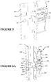
- the strike plate 125 comprises a first trigger 129 and a second trigger 229 (illustrated in Figures 6a and 6b ).
- the lock assembly 110 comprises a first sensor 106 for sensing the first trigger and a second sensor 107 for sensing the second trigger.
- the sensors each provide an output to the controller when the sensor is near to its corresponding trigger.
- the first and second triggers are offset to opposite side of a centre of the closed position of the door.
- the door closed position relative to the lock assembly and strike plate is indicated as a centre line 115 of the strike plate 125 in Figures 6a and 6b .
- the door is in the closed position when the centre lines of the lock assembly and the strike plate are approximately aligned.
- the first and second triggers 129, 229 are offset with respect to the closed position of the door, one trigger offset to one side of the centre of the door closed position, and the other trigger offset to the other side of the centre of the door closed position.
- the second trigger is positioned closer to the door first open position than the first trigger so that when the door moves from the first open position to the closed position in the first direction of rotation 123, the second sensor senses the second trigger (for example a magnet as described with reference to Figure 5 ) before the first sensor senses the first trigger so that the controller receives an output from the second sensor and actuates the second mechanism 220 to move the second pin 213 from the retracted position to the extended position before the controller actuates the first mechanism 120 to move the first pin 113 from the retracted position to the extended position.
- the first pin may not align with the first opening 126 and impeded or prevent the door reaching the closed position.
- the first sensor senses the first trigger before the second sensor senses the second trigger so that the controller receives a first output from the first sensor and actuates the first mechanism to move the first pin from the retracted position to the extended position before the controller actuates the second mechanism to move the second pin from the retracted position to the extended position.
- the triggers are aligned at the strike plate and the first and second sensors are offset at the lock assembly, so that the sensor and trigger pairs are directionally biased.
- the lock assembly comprises a first motor to move the first pin from the retracted position to the extended position, and a second motor to move the second pin from the retracted position to the extended position.
- the lock assembly 10, 110 comprises a mechanism 20, 120, 220.
- the mechanism operates to support the pin so that a force acting on a locking surface of the pin when the pin is in the extended position is substantially transferred through a structural member of the mechanism and prevent or reduce force acting on a latch for holding the pin in the extended position.
- the mechanism is adapted to move the pin 13, 113, 213 between the retracted position and the extended position.
- An actuator is provided for driving or actuating the pin from the retracted position to the extended position.
- the actuator moves the pin via the mechanism.
- the actuator is a rotational motor 30, 130, 230.
- the motor is coupled to the pin via the mechanism.
- the controller drives or actuates the motor to operate the mechanism.
- the motor is energised to move from a first position to a second position to move the pin from the retracted position to the extended position.
- a spring 35, 135, 235 biases the pin to the retracted position.
- the spring acts on the mechanism to bias the pin to the retracted position.
- the motor works against the spring.
- the controller is programmed to drive the motor in a forward direction from the first position to the second position to move the pin from the retracted position to the extended position. With the pin in the extended position the latch is moved to the latched position to hold the pin in the extended position. With the pin retained in the extended position by the latch, the controller drives the motor to disengage the mechanism from the pin. In the preferred embodiment the motor is driven in a reverse direction from the second position to the first position or an intermediate position between the first and second positions to disengage the motor from the pin.
- the lock remains in this locked state, with the latch maintaining the pin in the extended position and the motor driven away from the second position to or towards the first position, until an unlock signal is received by the controller to initiate an unlock operation.
- the lock may be provided with a push button for a user to operate to unlock a door.
- the controller is programmed to actuate the latch to the unlatch position. Once the latch is moved to the unlatched position and releases the pin, the pin moves to the retracted position under action of the spring. This movement from the extended position to the retracted position occurs rapidly since the motor is disengaged from the pin. In the preferred embodiment, the motor has moved away from the second position to towards the first position before the unlock operation is initiated. Operation of the latch to release the pin and move the pin by a spring force is significantly faster than an arrangement where an actuator strokes the pin from the extended position to the retracted position.
- a rapid retraction of the pin may not be achieved when using a motor or other energisable actuator to stroke the pin from the extended position to the retracted position is since the motor movement is not as fast as movement under action of a spring which rapidly snaps the pin to the retracted position.
- the term 'motor position' used in this specification and claims refers to a relative position of a rotational motor shaft or a moving part of a linear motor or other actuator.
- the shaft of a motor may turn through one revolution to move from a first (starting) position to a second position.
- the degrees of movement of a motor shaft between a first position and a second position to move the pin from the retracted position to the extended position depends on a gear ratio between the motor and the pin.
- the controller actuates the latch to move the latch to the latched or unlatched positions, via for example a latch actuator.
- the actuator is a linear actuator, for example a solenoid operated latch bolt.
- the actuator for actuating the pin is also the latch actuator..
- the motor 30, 130, 230 is energised to both move the pin and operate the latch.
- a pinion wheel 50 is attached to a drive shaft of the motor (not shown).
- the pinion wheel drives a driven member 65 about a shaft 68 via a rack 66 attached to or integrally formed with the driven member.
- the driven member comprises a projection 67 for triggering a latch described below.
- a linkage 44 is coupled to the pin 13.
- the linkage comprises a first arm 45 and a second arm 46 rotationally coupled together by a linkage shaft 47.
- the first arm 45 is rotationally coupled to the pin 13 via a first arm shaft 43.
- the first arm shaft is spaced a distance from the pin shaft 22.
- the second arm is rotationally supported in spaced relation from the pin by a second arm shaft 48.
- the second arm shaft 48 and the driven member shaft share a common axis.
- the second arm shaft 48 and the driven member shaft are a single (the same) component.
- Figures 8A and 9A illustrate the mechanism with the pin in the retracted position. With the pin in the retracted position, an angle between the first and second linkage arms is an acute angle.
- Figures 8F and 9F illustrate the mechanism with the pin in the extended position. With the pin in the extended position, the first and second linkage arms are preferably substantially aligned. With the pin in the extended position, the first arm shaft 43, the linkage shaft and the second arm shaft 47 are preferably substantially aligned. With the pin in the extended position, preferably the linkage shaft, the first arm shaft and the second arm shaft are substantially aligned on a line substantially parallel to a plane (60, Figure 7 ) of the door when the door is in the closed position.
- a force provided to the lock surface of the pin creates a moment about the pin shaft.
- the moment causes a force to be transmitted into the linkage.
- a significant component of the force is transmitted along the linkage and is reacted at the second arm shaft. Therefore a force applied to the lock surface of the pin is mostly transferred to or reacted by the pin shaft and transmitted through the linkage to a linkage support (the second arm shaft).
- a force on the locking surface of the pin does not significantly transmit to other components of the mechanism, for example a latch for holding the pin in the extended position or an actuator for driving the pin between the retracted and extended positions.
- the linkage is adapted so that when moving the pin from the retracted position to the extended position a centre of the linkage shaft 47 passes through a line extending between the centre of the first arm shaft 43 and a centre of the second arm shaft 48 so that in the extended position the angle between the first and second arms is greater than 180 degrees.
- This position is best shown in Figure 10 .
- the centre of the linkage shaft 47 has passed through a line 42 extending between the first arm shaft 43 and the second arm shaft 48.
- a force provided to the lock surface of the pin creates a moment about the pin shaft.
- the moment causes a force to be transmitted into the linkage.
- the force acts on the linkage to collapse the linkage in an opposite direction to the direction the linkage collapses when moving the pin to the retracted position.
- the effect of the over centre linkage is to cause a force on the locking surface of the pin to act on the linkage in an opposite direction to the action of the mechanism spring 35.
- a force on the locking surface of the pin can overcome the force of the spring. Therefore a significant force on the pin locking surface acts to hold the pin in the extended direction and not push the pin to the retracted position.
- the over centre arrangement makes the lock significantly robust.
- An actuator initially moves the linkage to retract the pin.
- the motor initially moves the linkage so that the pin may be retracted under action of the spring.
- the angle between the first and second arms is slightly greater than 180°.
- the linkage shaft and the first and second arm shafts are substantially aligned.
- the angle between the first and second arms is between 180° and 181°.
- the motor initiates movement of the linkage to retract the pin via an unlock mechanism described below.
- the motor is capable of initiating retraction of the extended pin when a force of more than 1000N is applied to a door which causes more than 1000N loading on the locking surface of the pin.
- the lock comprises a locking mechanism driven by the motor.
- the locking mechanism is adapted to contact the linkage when the motor is driven in the forward direction to move the pin from the retracted position to the extended position.
- the locking mechanism is the driven member.
- the driven member 65 is adapted to contact the linkage 44 when the motor is driven in the forward direction to move the pin from the retracted position to the extended position.
- the driven member is adapted to contact the linkage shaft 47.
- the driven member comprises a recess 64 for receiving the linkage shaft.
- the recess can be partially seen in Figure 8E . A portion of an adjacent part is cut away in Figure 11 so the recess 64 is shown clearly, with the linkage shaft 47 received in the recess.
- the recess is open to a side so that the linkage shaft is released from the recess when the motor is driven in the reverse direction.
- the latch comprises a latch arm 36 for retaining the pin in the extended position when the latch arm is in the latched position.
- the latch arm contacts the linkage to retain the pin in the extended position.
- the latch arm is pivotally mounted on a latch arm shaft 40 to move between the latched and unlatched positions.
- a link arm 37 is pivotally connected to the latch arm 36.
- the link arm and latch arm are pivotally connected via a latch shaft 39.
- the latch shaft is received in a slot in the latch arm to allow translational movement between the latch arm and the link arm at the pivot point between the link and latch arms.
- the latch arm In the latched position, the latch arm contacts the linkage shaft to retain the pin in the extended position. As shown in Figure 8E , an end 42 of the latch arm contacts the linkage shaft. In the unlatched position, the latch arm is pivoted about the latch arm shaft to move the end of the latch arm away from the linkage shaft to allow the pin to move from the extended position to the retracted position.
- the linkage arm is shown in the unlatched position in Figures 8G , 9G and 10 where the linkage shaft is free to move past the end 42 of the latch arm 36.
- the latch comprises a latch spring 41, 141, 241 ( Figures 1 , 3 , 4 and 5 ) for biasing the latch arm to the latched position.
- the spring acts on the linkage arm to bias the latch arm to the latched position.
- a latch trigger 67 driven by the motor is adapted to move the latch between the latched and unlatched positions.
- the latch trigger is a projection 67 extending from the driven member 65. Movement of the motor in the reverse direction causes the projection 67 to contact the link arm 37 to shift the position of the link arm to pivot the latch arm from the latched to the unlatched position.
- the lock comprises an unlocking mechanism for 'kick starting' movement of the pin from the extended position to the retracted position to overcome the over centre position of the linkage.
- the unlocking mechanism is driven by the motor 30, 130, 230.
- the unlocking mechanism comprises the driven member 65 and driven member projection 67, and an unlock cam 55 comprising a slot 56.
- the unlock cam is supported on a shaft 54 for rotation about the shaft.
- the unlock cam shaft and the driven member shaft share a common axis.
- the unlock cam shaft and the driven member shaft are a single (the same) component.
- the pin 13 is in the retracted position, and the latch 36 is in the unlatched position.
- the motor is in the first position.
- the latch is held in the unlatched position by the driven member projection 67 acting on the link arm against the latch spring (not shown in Figures 8 and 9 ).
- the linkage 44 is in a collapsed position, there being an acute angle between the first 45 and second 46 linkage arms.
- the motor moves in the forward direction from the first position to the second position.
- Rotation of the motor drives the driven member 65 via the pinion 50 and rack 66.
- the linkage shaft 47 is captured by the recess 64 (obscured from view in Figures 8b and 9b ) in the driven member so that motor movement straightens the linkage and pivots the pin about the pin shaft 22 to move the pin towards the extended position.
- the driven member projection 67 has lost contact with the link arm 37.
- the link arm moves under action of the latch spring 41 and the latch arm 36 pivots about the latch arm shaft to move to the latched position.
- the driven member projection travels along a slot 56 in the unlock cam 55.
- the motor has moved closer to the second position. Movement of the driven member continues to straighten the linkage 44.
- the linkage shaft 47 has contacted the latch arm.
- the motor has reached the second position.
- the linkage shaft 47 has passed beyond the end 42 of the latch arm 36 so that the latch arm moves to the latched position under action of the latch spring 41.
- the forward motor movement from Figures 8d , 9d to Figures 8e , 9e has moved a centre of the linkage shaft through a line between the first arm shaft and the second arm shaft as illustrated in and described earlier with reference to Figure 10 .
- the angle between the first and second linkage arms is more than 180°.
- the centre of the linkage shaft does not pass through a line between the first arm shaft and the second arm shaft, the angle between the first and second linkage arms being less than 180°.
- the angle between the linkage arms changes from acute with the pin retracted to obtuse when the pin is extended.
- the unlock cam 55 has rotated a small distance about the unlock cam shaft 54, being driven by contact between the end 57 of the unlock cam slot 56 and the linkage shaft 47.
- the linkage shaft is captured between the end of the latch arm 36 and the end of the slot of the unlock cam 55.
- a force applied to the locking surface of the pin 13 acts against the spring when the linkage is over centre to prevent the pin from moving from the extended position to the retracted position.
- a limit to movement of the pin when moving to the extended position is provided by the end 57 of the unlock cam slot 55.
- rotation of the unlock cam is limited at the position shown in Figures 8e and 9e .
- the extended position is defined by the linkage shaft hitting end stops in two spaced apart walls.
- Figure 12 illustrates the mechanism 20 including two walls 71, 72. Walls 71, 72 are omitted from Figures 8 and 9 for clarity. As shown in Figure 12 , each end of the linkage shaft 47 is received in a slot 73, 74 in one wall 71, 72. A first end 75, 76 of each slot 73, 74 define a maximum retracted position of the pin. A second end 77, 78 of each slot 73, 74 define a maximum extended position of the pin. In the embodiment of Figure 3 , one wall 71 preferably receives the linkage shaft from both mechanisms 120 and 220.
- the linkage shaft 47 When a large force is applied to the locking surface of the pin and with the linkage over centre, the force on the pin can drive the linkage shaft 47 into the ends 77, 78 of the wall slots.
- the linkage shaft may not contact the ends of the wall slots even when a large force is applied to the pin since the linkage is effectively balanced due to being substantially aligned.
- the motor has moved in the reverse direction to a position intermediate between the first and second positions.
- the latch arm 36 retains the pin 13 in the extended position, the end 42 of the latch arm 36 holding the linkage shaft.
- the driven member projection 67 may contact the latch link arm 37 but does not move the link arm so that the latch arm remains in the latched position.
- the motor is disengaged from the pin by moving the motor in the reverse direction so that the linkage shaft is released from the driven member recess 64 (obscured from view in Figures 8f and 9f ).
- the latch may be actuated by a separate latch actuator.
- the motor may return to the first motor position with the latch remaining in the latched position.
- the motor has moved in the reverse direction from the intermediate position to a third position to actuate the latch to move the latch arm 36 to the unlatched position.
- the driven member projection 67 moves the link arm 37 to pivot the latch arm to the unlatched position.
- the driven member projection 67 makes contact with a first end 58 of the slot 56 of the unlock cam 55.
- the linkage shaft is in contact with a second opposite end 57 of the unlock cam slot.
- the unlock cam 55 couples the motor to the pin 13.
- the unlock cam couples the motor to the pin, one end of the unlock cam shaft in contact driven member projection, and the opposite end of the unlock cam slot in contact with the linkage shaft.
- the motor is coupled to the pin via the unlock cam and the linkage.
- the pin moves to the retracted position under action of the spring (regardless of whether there is a load on the locking surface of the pin), since the angle between the first and second linkage arms is less than 180°.
- the motor may move from the intermediate position to the first position, to actuate the latch from the latched position to the unlatched position to return the pin to the retracted position.
- the intermediate is near to the first position, so that a relatively small motor movement is required to operate the latch to the unlatched position and move the pin to the retracted position.
- the pin can move to the retracted position under action of the spring 35 (not shown in Figures 8 and 9 ).
- the motor moves from the third position to the first position.
- the motor is coupled to the pin via the unlock cam and the linkage. Movement of the motor from the third position to the first position moves unlock cam 55 and therefore the linkage 44 from the over centre position to allow the linkage to collapse under action of the spring and return the pin to the retracted position under action of the spring.
- the linkage is slightly over centre when the pin is in the extended position.
- the link arms are (or first arm shaft, second arm shaft and linkage shaft) are approximately aligned so that a relatively small lateral force is required to 'kick' the linkage from the over centre position to allow the linkage to collapse under action of the spring and a force on the pin surface.
- the lock preferably comprises a first limit switch, a second limit switch and a third limit switch for communicating to the controller when the motor has reached the first position, the second position and the intermediate position.
- the motor preferably does not stop movement at the third position when moving from the intermediate position to the first position.
- the motor passes through the third position when moving from the intermediate position to the first position.
- the driven member comprises a post or feature 63 ( Figure 9a ) for contacting the limit switches to trip the limit switches.
- the lock also comprises a fourth limit switch and a fifth limit switch for communicating to the controller when the pin has reached the retracted and extended positions.
- the lock may provide an output for providing a signal to a system for controlling or monitoring the position of the pin being in the retracted or extended positions.
- the fourth and fifth limit switch are tripped by a feature on the pin or on the mechanism for moving the pin, for example a feature on the linkage or driven member.
- a knob 62 ( Figure 8b ) is provided on the second linkage arm 46 for tripping the pin position limit switches.
- the lock of Figures 3, 4 and 6 comprises a first current monitoring circuit for communicating to the controller an electrical current drawn by the first motor, and a second current monitoring circuit for communicating to the controller an electrical current drawn by the second motor.
- the controller is programmed to drive the first motor to move the first pin from the extended position to the retracted position and drive the second motor to move the second pin from the extended position to the retracted position.
- the controller monitors a first electrical current drawn by the first motor and a second electrical current drawn by the second motor required to actuate the first and second pins.
- the controller calculates a difference between the electrical currents and compares this difference to a predetermined threshold.
- the threshold may be set at zero. If the difference is greater than the threshold and the first electrical current is greater than the second electrical current, the controller controls the first and second motors to move the second pin to the retracted position before the first pin. If the difference is greater than the threshold and the second electrical current is greater than the first electrical current, the controller controls the first and second motors to move the first pin to the retracted position before the second pin. For example, if the difference is greater than the threshold and the first electrical current is greater than the second electrical current, the controller stops driving the first motor, and drives the second motor to move the second pin to the retracted position.
- the controller drives the first motor to move the first pin to the retracted position.
- the controller delays commencement of movement of the first motor by a predetermined delay period.
- the controller stops driving the second motor, and drives the first motor to move the first pin to the retracted position.
- the controller drives the second motor to move the second pin to the retracted position, or delays movement of the first motor by a predetermined delay period.
- This relative control of the first and second pin movement can be important where there is a force applied to the door when closed and locked with the first and second pins in the extended positions and received in the first and second openings in the strike plate.
- a force applied in the first direction 123 to the closed and locked door will cause a force on the lock surface of the first pin 113 in the first direction by contact between edge 128 of the first opening 126 and the first pin ( Figures 6a and 6b ).
- this force on the extended door pin as illustrated by arrow 17 in Figure 10 will act to hold the first pin in the extended position and cause the current drawn by the first motor to be higher than the current drawn by the second motor to move the first and second pins. Therefore by comparing the motor currents, the controller can identify a force acting on the door and the direction of that force. Were the controller to continue to energise the first motor and cause the linkages of the first mechanism to collapse and/or move through the centre line of the linkages, the first pin will then move rapidly to the retracted position as it would then be assisted by the force on the pin. This can cause the first pin to retract more quickly than the second pin.
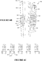
- the strike plate 125 may comprise a roller or rollers at an edge of the first opening and an edge of the second opening, as illustrated in Figure 6b .
- Each roller 151, 251 is rotationally mounted to the strike to rotate on a roller shaft (for example shaft 252 in Figure 6c .
- a force applied in the first direction 123 to the closed and locked door will cause a force on the lock surface of the first pin 113 in the first direction by contact between edge 128 of the first opening 126 and the lock surface of the first pin ( Figure 6b ).
- this force on the extended door pin will act to cause the first pin to move rapidly to the retracted position, as the pin will be assisted by the force on the pin. This can cause the first pin to retract more quickly than the second pin.
- the force on the door can cause the door to start to pivot open before the second pin 213 is retracted.
- the roller 251 of the second opening may contact the curved back side of the second pin 213, as illustrated in Figure 6c .
- contact between the curved surface of the second door pin and the roller 251 does not stall the second door pin. The roller rotates as the pin pivots to allow the second pin to retract to the retracted position while there is contact between the pin and the roller.
- contact may occur between the back or curved side of the first pin 113 and the roller 151 due to the second pin retracting to the retracted position before the first pin.
- the roller 151 rotates as the pin pivots to allow the first pin to retract to the retracted position while there is contact between the pin and the roller.
- the rollers 151, 251 reduce or prevent the risk of jamming the door on the back side of one of the pins.
- the lock 10, 110 comprises a motor current detection circuit for communicating to the controller an electrical current drawn by the motor 30, 130, 230.
- the controller is programmed to monitor the electrical current drawn by the motor and compare the electrical current to a predetermined threshold.
- the controller drives the motor in a forward direction to move the pin from the retracted position towards the extended position. If the electrical current increases above the threshold, this provides an indication to the controller that the pin has clashed with the door or door frame (or the strike plate attached to the door or door frame). Where the current increases above the threshold, the controller drives the motor in the reverse direction to retract the pin.
- the motor may drive the motor to the first motor position, or for a determined time period.
- the motor then drives the pin to the extended position, by which time any door and door frame misalignment may have been corrected (by the door reaching the closed position) and a successful locking operation is achieved.
- the controller attempts to successfully extend the pin a predetermined number of times before a fault condition is registered or the lock terminates further attempts to lock the door.
- the lock according to the present invention has been described as a lock for locking a door to a door frame.
- a lock according to the present invention is equally suitable for locking a cupboard door to a cabinet, or any other door to a fixed structure that surrounds the door or is fixed adjacent to the door when in the closed position.
- the term door frame is intended to be interpreted broadly to cover any frame or structure such as a cupboard wall to which a door may be locked in a closed position.
- the term door is also intended to be interpreted broadly to mean any barrier moveable between a closed and open position, for example a gate lockable to a fence.
Landscapes
- Engineering & Computer Science (AREA)
- Structural Engineering (AREA)
- Physics & Mathematics (AREA)
- Electromagnetism (AREA)
- Lock And Its Accessories (AREA)
Claims (15)
- Serrure pour verrouiller une porte, la serrure comprenant :une goupille (13, 113, 213) mobile entre une position rétractée et une position déployée pour verrouiller la porte,un actionneur (30, 130, 230) mobile d'une première position à une deuxième position pour déplacer la goupille (13, 113, 213) de la position rétractée à la position déployée,caractérisée par :un mécanisme (20, 120, 220) comprenant :un ressort (35, 135, 235) pour solliciter la goupille (13, 113, 213) jusqu'à la position rétractée,un verrou (36, 136, 236), dans une position verrouillée le verrou (36, 136, 236) empêchant la goupille (13, 113, 213) de se déplacer de la position déployée à la position rétractée, et dans une position déverrouillée le verrou (36, 136, 236) permettant à la goupille (13, 113, 213) de se déplacer de la position déployée à la position rétractée, etle mécanisme (20, 120, 220) étant apte à désaccoupler l'actionneur (30, 130, 230) de la goupille lorsque la goupille est dans la position déployée,un dispositif de commande (5, 105),l'actionneur étant un moteur (30, 130, 230) comportant un arbre de moteur pour entraîner la goupille (13, 113, 213) de la position rétractée à la position déployée et le verrou (36, 136, 236) étant apte à être actionné par le moteur (30,130, 230),pour une opération de verrouillage de porte, le dispositif de commande étant programmé pour :entraîner le moteur (30, 130, 230) dans une direction avant de la première position à la deuxième position afin de déplacer la goupille (13, 113, 213) de la position rétractée à la position déployée et déplacer le verrou (36, 136, 236) jusqu'à la position verrouillée,entraîner le moteur (30, 130, 230) dans une direction inverse de la deuxième position à une position intermédiaire entre les première et deuxième positions de manière à désaccoupler le moteur (30, 130, 230) de la goupille (13, 113, 213), le verrou (36, 136, 236) maintenant la goupille dans la position déployée, etpour une opération de déverrouillage de porte, le dispositif de commande étant programmé pour :
entraîner le moteur (30, 130, 230) dans la direction inverse de la position intermédiaire à la première position afin de déplacer le verrou (36, 136, 236) jusqu'à la position déverrouillée afin de permettre à la goupille (13, 113, 213) de se déplacer jusqu'à la position rétractée sous l'action du ressort (35, 135, 235). - Serrure selon la revendication 1, dans laquelle la position intermédiaire est adjacente à la première position de manière qu'un mouvement de moteur relativement petit soit requis pour actionner le verrou (36, 136, 236) jusqu'à la position déverrouillée et déplacer la goupille (13, 113, 213) jusqu'à la position rétractée.
- Serrure selon la revendication 1 ou 2, dans laquelle le mécanisme comprend une biellette accouplée à la goupille, la biellette (44) comprenant :un premier bras (45) et un deuxième bras (46) accouplés en rotation l'un à l'autre par un arbre de biellette (47),le premier bras (45) accouplé en rotation à la goupille (13, 113, 213) par le biais d'un premier arbre de bras (43), etle deuxième bras (46) supporté en rotation en étant espacé de la goupille (13, 113, 213) par un deuxième arbre de bras (48),lorsque la goupille (13, 113, 213) est dans la position rétractée, un angle entre les premier et deuxième bras est un angle aigu ou le premier arbre de bras (43), le deuxième arbre de bras (48) et l'arbre de biellette (47) sont sensiblement non alignés, et lorsque la goupille (13, 113, 213) est dans la position déployée l'arbre de biellette (47), le premier arbre de bras (43) et le deuxième arbre de bras (48) sont sensiblement alignés.
- Serrure selon la revendication 3, dans laquelle lorsque la goupille (13, 113, 213) est dans la position déployée, l'arbre de biellette (47), le premier arbre de bras (43) et le deuxième arbre de bras (48) sont sensiblement alignés sur une ligne sensiblement parallèle à un plan de la porte lorsque dans la position fermée.
- Serrure selon la revendication 1 ou 2, dans laquelle le mécanisme comprend une biellette (44) accouplée à la goupille (13, 113, 213), la biellette comprenant :un premier bras (45) et un deuxième bras (46) accouplés en rotation l'un à l'autre par un arbre de biellette (47),le premier bras (45) accouplé en rotation à la goupille par le biais d'un premier arbre de bras (43), etle deuxième bras (46) supporté en rotation en étant espacé de la goupille par un deuxième arbre de bras (48),lorsque la goupille (13, 113, 213) est dans la position rétractée, un angle entre les premier et deuxième bras est un angle aigu ou le premier arbre de bras (43), le deuxième arbre de bras (48) et l'arbre de biellette (47) sont sensiblement non alignés, etla biellette (44) étant conçue pour que, lors du déplacement de la goupille (13, 113, 213) de la position rétractée à la position déployée, un centre de l'arbre de biellette (47) passe par une ligne s'étendant entre le centre du premier arbre de bras (43) et un centre du deuxième arbre de bras (48), dans la position déployée l'angle entre les premier et deuxième bras (45, 46) étant supérieur à 180 degrés.
- Serrure selon la revendication 5, dans laquelle le centre de l'arbre de biellette (47) passe par une ligne s'étendant entre le centre du premier arbre de bras (43) et un centre du deuxième arbre de bras (48) sur une petite distance, l'angle entre les premier et deuxième bras étant inférieur à environ 181 degrés.
- Serrure selon la revendication 5 ou 6, dans laquelle, pour une opération de déverrouillage de porte, le dispositif de commande (5, 105) étant programmé pour :entraîner le moteur (30, 130, 230) dans la direction inverse de la position intermédiaire à une troisième position entre la position intermédiaire et la première position de manière à déplacer le verrou (36, 136, 236) jusqu'à la position déverrouillée, etentraîner le moteur (30, 130, 230) dans la direction inverse de la troisième position à la première position de manière à déplacer la biellette (44) afin que le centre de l'arbre de biellette (47) passe par une ligne s'étendant entre le centre du premier arbre de bras (43) et un centre du deuxième arbre de bras (48) afin que la goupille (13, 113, 213) se déplace jusqu'à la position rétractée sous l'action du ressort (35, 135, 235).
- Serrure selon l'une quelconque des revendications 3 à 7, dans laquelle le mécanisme (20, 120, 220) comprend un mécanisme de verrouillage (65) entraîné par le moteur (30, 130, 230), le mécanisme de verrouillage (65) étant apte à entrer en contact avec la biellette (44) lorsque le moteur (30, 130, 230) est entraîné dans la direction avant afin de déplacer la goupille (13, 113, 213) de la position rétractée à la position déployée.
- Serrure selon la revendication 8, dans laquelle le mécanisme de verrouillage comprend un organe entraîné (65) entraîné par le moteur (30, 130, 230), l'organe entraîné (65) étant apte à entrer en contact avec la biellette (44) lorsque le moteur (30, 130, 230) est entraîné dans la direction avant afin de déplacer la goupille (13, 113, 213) de la position rétractée à la position déployée.
- Serrure selon la revendication 7, dans laquelle le mécanisme (20, 120, 220) comprend un mécanisme de déverrouillage (65, 67, 55) entraîné par le moteur, le mécanisme de déverrouillage (65, 67, 55) étant apte à entrer en contact avec la biellette (44) lorsque le moteur (30, 130, 230) est dans la troisième position de manière que le déplacement du moteur (30, 130, 230) de la troisième position à la première position déplace la biellette (44) afin que le centre de l'arbre de biellette passe par une ligne s'étendant entre le centre du premier arbre de bras (43) et un centre du deuxième arbre de bras (48) de manière que la goupille (13, 113, 213) se déplace jusqu'à la position rétractée sous l'action du ressort (35, 135, 235).
- Serrure selon la revendication 10, dans laquelle le mécanisme de déverrouillage (65, 67, 55) comprend :un organe de déverrouillage (65) entraîné par le moteur (30, 130, 230),une came de déverrouillage (55) pour accoupler l'organe de déverrouillage (65) et la biellette (44) lorsque le moteur (30, 130, 230) est déplacé dans la direction inverse jusqu'à la troisième position.
- Serrure selon la revendication 11, dans laquelle l'organe de déverrouillage est un organe entraîné (65) entraîné par le moteur (30, 130, 230), l'organe entraîné (65) comprenant une saillie (67) et la came de déverrouillage (55) comprend une fente (56) destinée à recevoir la saillie (67), et lorsque le moteur (30, 130, 230) est dans la troisième position, la saillie (67) porte contre une première extrémité (58) de la fente (56) et la biellette (44) porte contre une seconde extrémité opposée (57) de la fente pour accoupler la biellette (44) au moteur (30, 130, 230) par le biais de la came de déverrouillage (55) et de l'organe entraîné (65).
- Serrure selon la revendication 9 ou 12, dans laquelle le mécanisme (20, 120, 220) comprend un pignon (50) fixé à un arbre du moteur (30, 130, 230), et l'organe entraîné (65) comprend une crémaillère (66) engagée avec le pignon (50).
- Serrure selon l'une quelconque des revendications 10 à 13, dans laquelle le mécanisme (20, 120, 220) comprend un deuxième ressort (41, 141, 241) pour solliciter le verrou (36, 136, 236) jusqu'à la position verrouillée.
- Serrure selon la revendication 14, dans laquelle le verrou (36, 136, 236) comprend un bras de verrou (36) pour entrer en contact avec la biellette (44) afin de retenir la goupille (13, 113, 213) dans la position déployée, le bras de verrou (36) étant monté pivotant sur un arbre de verrou (39) pour déplacement entre les positions verrouillée et déverrouillée.
Applications Claiming Priority (2)
| Application Number | Priority Date | Filing Date | Title |
|---|---|---|---|
| NZ59995512 | 2012-05-11 | ||
| PCT/IB2013/053737 WO2013168114A1 (fr) | 2012-05-11 | 2013-05-09 | Serrure |
Publications (3)
| Publication Number | Publication Date |
|---|---|
| EP2847401A1 EP2847401A1 (fr) | 2015-03-18 |
| EP2847401A4 EP2847401A4 (fr) | 2017-01-18 |
| EP2847401B1 true EP2847401B1 (fr) | 2018-07-04 |
Family
ID=49550256
Family Applications (1)
| Application Number | Title | Priority Date | Filing Date |
|---|---|---|---|
| EP13788401.1A Active EP2847401B1 (fr) | 2012-05-11 | 2013-05-09 | Serrure |
Country Status (5)
| Country | Link |
|---|---|
| US (1) | US10316549B2 (fr) |
| EP (1) | EP2847401B1 (fr) |
| AU (1) | AU2013257648B2 (fr) |
| WO (1) | WO2013168114A1 (fr) |
| ZA (1) | ZA201408699B (fr) |
Families Citing this family (9)
| Publication number | Priority date | Publication date | Assignee | Title |
|---|---|---|---|---|
| CA3000158C (fr) * | 2012-07-13 | 2021-05-18 | Schlage Lock Company Llc | Systeme de compensation de precontrainte d'ensemble verrou de porte electronique |
| US9435142B2 (en) | 2014-02-28 | 2016-09-06 | Schlage Lock Company Llc | Method of operating an access control system |
| MX385413B (es) * | 2015-09-08 | 2025-03-18 | Janus Int Group Llc | Aparato de cierre electrónico para una puerta enrollable. |
| CN106593095B (zh) * | 2017-03-02 | 2019-04-05 | 北京火河科技有限公司 | 一种锁体的斜锁舌结构 |
| TWI620862B (zh) * | 2017-06-28 | 2018-04-11 | Tong Lung Metal Industry Co Ltd | 電子鎖及其電控裝置與運作定位偵測方法 |
| US11730296B2 (en) * | 2019-02-12 | 2023-08-22 | Clevon As | Locking device and method for a parcel box |
| US11719021B2 (en) | 2019-08-06 | 2023-08-08 | Schlage Lock Company Llc | Sensing and control of access control devices |
| WO2023114909A1 (fr) * | 2021-12-17 | 2023-06-22 | Spectrum Brands, Inc. | Verrou électronique avec insert de mortaise |
| CN118622078A (zh) * | 2023-03-10 | 2024-09-10 | 安克创新科技股份有限公司 | 锁具以及锁具开关锁的控制方法 |
Family Cites Families (15)
| Publication number | Priority date | Publication date | Assignee | Title |
|---|---|---|---|---|
| US2325225A (en) * | 1942-05-09 | 1943-07-27 | Nat Lock Co | Refrigerator latch |
| US3751088A (en) * | 1971-05-24 | 1973-08-07 | Schlage Lock Co | Electromagnetic lock |
| US4021065A (en) | 1975-07-08 | 1977-05-03 | Geringer Arthur V | Electric lock |
| US4056276A (en) | 1976-04-05 | 1977-11-01 | Jarvis Kenneth W | Door lock |
| US4237711A (en) * | 1978-02-10 | 1980-12-09 | Brink's Locking Systems, Inc. | Lock mechanism |
| US4685709A (en) * | 1984-05-29 | 1987-08-11 | R. R. Brink Locking Systems, Inc. | Deadlocked latch having disc and motor actuators |
| GB2230550B (en) | 1989-03-18 | 1993-02-10 | Walter Wilson Hugh Clarke | Electromagnetic door lock |
| US5113676A (en) * | 1990-12-31 | 1992-05-19 | Misak Panossian | Double acting dead latch mechanism |
| US5566991A (en) * | 1994-10-28 | 1996-10-22 | R R Brink Locking Systems, Inc. | Lock with cam operated mechanism |
| US5755126A (en) * | 1995-09-22 | 1998-05-26 | Lanigan; William P. | Security system for cargo loading doors |
| DE19613638C2 (de) | 1996-04-04 | 1998-03-19 | Simons & Vos Identifikationssy | Schloß |
| GB0309266D0 (en) * | 2003-04-24 | 2003-06-04 | Arvinmeritor Light Vehicle Sys | A lock mechanism |
| DE10327997A1 (de) * | 2003-06-21 | 2005-01-13 | Huf Hülsbeck & Fürst Gmbh & Co. Kg | Schloss für Türen oder Klappen an Fahrzeugen |
| FR2911898B1 (fr) * | 2007-01-25 | 2019-06-07 | Saint Gobain Seva | Dispositif d'actionnement de pene et porte equipee dudit dispositif. |
| GB2446804B (en) * | 2007-02-23 | 2011-07-13 | Meritor Technology Inc | Latch Mechanism |
-
2013
- 2013-05-09 AU AU2013257648A patent/AU2013257648B2/en active Active
- 2013-05-09 WO PCT/IB2013/053737 patent/WO2013168114A1/fr not_active Ceased
- 2013-05-09 US US14/398,788 patent/US10316549B2/en active Active
- 2013-05-09 EP EP13788401.1A patent/EP2847401B1/fr active Active
-
2014
- 2014-11-26 ZA ZA2014/08699A patent/ZA201408699B/en unknown
Non-Patent Citations (1)
| Title |
|---|
| None * |
Also Published As
| Publication number | Publication date |
|---|---|
| US10316549B2 (en) | 2019-06-11 |
| AU2013257648B2 (en) | 2018-05-10 |
| EP2847401A4 (fr) | 2017-01-18 |
| AU2013257648A1 (en) | 2014-12-18 |
| US20150097380A1 (en) | 2015-04-09 |
| ZA201408699B (en) | 2015-11-25 |
| EP2847401A1 (fr) | 2015-03-18 |
| WO2013168114A1 (fr) | 2013-11-14 |
Similar Documents
| Publication | Publication Date | Title |
|---|---|---|
| EP2847401B1 (fr) | Serrure | |
| US9850684B2 (en) | Sensor assemblies for locks | |
| EP2931996B1 (fr) | Dispositif de rétraction de loquet électrique pour loquets de porte à tige verticale | |
| US11572711B2 (en) | Dead bolt lock system and method of retracting a dead bolt | |
| FI87681C (fi) | Elektromekaniskt doerrlaos | |
| CN104956019B (zh) | 用于车门的关闭闩锁 | |
| US11851913B2 (en) | Hook bolt for door lock | |
| CN108252574B (zh) | 锁具的滑动致动器总成 | |
| DK2525025T3 (en) | Electronic unit for a blocking device and locking system | |
| US11851925B2 (en) | Key override for electromechanical multi-point latching device | |
| WO2018208674A1 (fr) | Ensemble verrou à pêne dormant à déploiement automatique | |
| CA2537540C (fr) | Systeme de verrouillage | |
| CN114450460B (zh) | 闩锁组件 | |
| NZ610372B2 (en) | A lock | |
| NZ610372A (en) | A lock | |
| TWI911090B (zh) | 智慧門鎖機構 | |
| TWI923385B (zh) | 智慧門鎖機構 | |
| HK1070678B (en) | Electric drop bolt with slidable drive mechanism | |
| HK1070678A1 (en) | Electric drop bolt with slidable drive mechanism |
Legal Events
| Date | Code | Title | Description |
|---|---|---|---|
| PUAI | Public reference made under article 153(3) epc to a published international application that has entered the european phase |
Free format text: ORIGINAL CODE: 0009012 |
|
| 17P | Request for examination filed |
Effective date: 20141211 |
|
| AK | Designated contracting states |
Kind code of ref document: A1 Designated state(s): AL AT BE BG CH CY CZ DE DK EE ES FI FR GB GR HR HU IE IS IT LI LT LU LV MC MK MT NL NO PL PT RO RS SE SI SK SM TR |
|
| AX | Request for extension of the european patent |
Extension state: BA ME |
|
| DAX | Request for extension of the european patent (deleted) | ||
| RA4 | Supplementary search report drawn up and despatched (corrected) |
Effective date: 20161216 |
|
| RIC1 | Information provided on ipc code assigned before grant |
Ipc: E05B 65/06 20060101ALI20161212BHEP Ipc: E05C 3/12 20060101ALI20161212BHEP Ipc: E05B 17/20 20060101AFI20161212BHEP Ipc: E05B 63/14 20060101ALI20161212BHEP Ipc: E05B 47/00 20060101ALI20161212BHEP |
|
| GRAP | Despatch of communication of intention to grant a patent |
Free format text: ORIGINAL CODE: EPIDOSNIGR1 |
|
| STAA | Information on the status of an ep patent application or granted ep patent |
Free format text: STATUS: GRANT OF PATENT IS INTENDED |
|
| INTG | Intention to grant announced |
Effective date: 20171130 |
|
| GRAS | Grant fee paid |
Free format text: ORIGINAL CODE: EPIDOSNIGR3 |
|
| GRAA | (expected) grant |
Free format text: ORIGINAL CODE: 0009210 |
|
| STAA | Information on the status of an ep patent application or granted ep patent |
Free format text: STATUS: THE PATENT HAS BEEN GRANTED |
|
| AK | Designated contracting states |
Kind code of ref document: B1 Designated state(s): AL AT BE BG CH CY CZ DE DK EE ES FI FR GB GR HR HU IE IS IT LI LT LU LV MC MK MT NL NO PL PT RO RS SE SI SK SM TR |
|
| REG | Reference to a national code |
Ref country code: GB Ref legal event code: FG4D |
|
| REG | Reference to a national code |
Ref country code: CH Ref legal event code: EP |
|
| REG | Reference to a national code |
Ref country code: AT Ref legal event code: REF Ref document number: 1014677 Country of ref document: AT Kind code of ref document: T Effective date: 20180715 |
|
| REG | Reference to a national code |
Ref country code: IE Ref legal event code: FG4D |
|
| REG | Reference to a national code |
Ref country code: DE Ref legal event code: R096 Ref document number: 602013039789 Country of ref document: DE |
|
| REG | Reference to a national code |
Ref country code: CH Ref legal event code: NV Representative=s name: KIRKER AND CIE S.A., CH |
|
| REG | Reference to a national code |
Ref country code: NL Ref legal event code: FP |
|
| RAP2 | Party data changed (patent owner data changed or rights of a patent transferred) |
Owner name: BQT SOLUTIONS (SEA) PTE LIMITED |
|
| REG | Reference to a national code |
Ref country code: LT Ref legal event code: MG4D |
|
| REG | Reference to a national code |
Ref country code: AT Ref legal event code: MK05 Ref document number: 1014677 Country of ref document: AT Kind code of ref document: T Effective date: 20180704 |
|
| PG25 | Lapsed in a contracting state [announced via postgrant information from national office to epo] |
Ref country code: LT Free format text: LAPSE BECAUSE OF FAILURE TO SUBMIT A TRANSLATION OF THE DESCRIPTION OR TO PAY THE FEE WITHIN THE PRESCRIBED TIME-LIMIT Effective date: 20180704 Ref country code: PL Free format text: LAPSE BECAUSE OF FAILURE TO SUBMIT A TRANSLATION OF THE DESCRIPTION OR TO PAY THE FEE WITHIN THE PRESCRIBED TIME-LIMIT Effective date: 20180704 Ref country code: IS Free format text: LAPSE BECAUSE OF FAILURE TO SUBMIT A TRANSLATION OF THE DESCRIPTION OR TO PAY THE FEE WITHIN THE PRESCRIBED TIME-LIMIT Effective date: 20181104 Ref country code: RS Free format text: LAPSE BECAUSE OF FAILURE TO SUBMIT A TRANSLATION OF THE DESCRIPTION OR TO PAY THE FEE WITHIN THE PRESCRIBED TIME-LIMIT Effective date: 20180704 Ref country code: FI Free format text: LAPSE BECAUSE OF FAILURE TO SUBMIT A TRANSLATION OF THE DESCRIPTION OR TO PAY THE FEE WITHIN THE PRESCRIBED TIME-LIMIT Effective date: 20180704 Ref country code: SE Free format text: LAPSE BECAUSE OF FAILURE TO SUBMIT A TRANSLATION OF THE DESCRIPTION OR TO PAY THE FEE WITHIN THE PRESCRIBED TIME-LIMIT Effective date: 20180704 Ref country code: CZ Free format text: LAPSE BECAUSE OF FAILURE TO SUBMIT A TRANSLATION OF THE DESCRIPTION OR TO PAY THE FEE WITHIN THE PRESCRIBED TIME-LIMIT Effective date: 20180704 Ref country code: GR Free format text: LAPSE BECAUSE OF FAILURE TO SUBMIT A TRANSLATION OF THE DESCRIPTION OR TO PAY THE FEE WITHIN THE PRESCRIBED TIME-LIMIT Effective date: 20181005 Ref country code: NO Free format text: LAPSE BECAUSE OF FAILURE TO SUBMIT A TRANSLATION OF THE DESCRIPTION OR TO PAY THE FEE WITHIN THE PRESCRIBED TIME-LIMIT Effective date: 20181004 Ref country code: BG Free format text: LAPSE BECAUSE OF FAILURE TO SUBMIT A TRANSLATION OF THE DESCRIPTION OR TO PAY THE FEE WITHIN THE PRESCRIBED TIME-LIMIT Effective date: 20181004 Ref country code: AT Free format text: LAPSE BECAUSE OF FAILURE TO SUBMIT A TRANSLATION OF THE DESCRIPTION OR TO PAY THE FEE WITHIN THE PRESCRIBED TIME-LIMIT Effective date: 20180704 |
|
| PG25 | Lapsed in a contracting state [announced via postgrant information from national office to epo] |
Ref country code: HR Free format text: LAPSE BECAUSE OF FAILURE TO SUBMIT A TRANSLATION OF THE DESCRIPTION OR TO PAY THE FEE WITHIN THE PRESCRIBED TIME-LIMIT Effective date: 20180704 Ref country code: LV Free format text: LAPSE BECAUSE OF FAILURE TO SUBMIT A TRANSLATION OF THE DESCRIPTION OR TO PAY THE FEE WITHIN THE PRESCRIBED TIME-LIMIT Effective date: 20180704 Ref country code: ES Free format text: LAPSE BECAUSE OF FAILURE TO SUBMIT A TRANSLATION OF THE DESCRIPTION OR TO PAY THE FEE WITHIN THE PRESCRIBED TIME-LIMIT Effective date: 20180704 Ref country code: AL Free format text: LAPSE BECAUSE OF FAILURE TO SUBMIT A TRANSLATION OF THE DESCRIPTION OR TO PAY THE FEE WITHIN THE PRESCRIBED TIME-LIMIT Effective date: 20180704 |
|
| REG | Reference to a national code |
Ref country code: DE Ref legal event code: R097 Ref document number: 602013039789 Country of ref document: DE |
|
| PG25 | Lapsed in a contracting state [announced via postgrant information from national office to epo] |
Ref country code: IT Free format text: LAPSE BECAUSE OF FAILURE TO SUBMIT A TRANSLATION OF THE DESCRIPTION OR TO PAY THE FEE WITHIN THE PRESCRIBED TIME-LIMIT Effective date: 20180704 Ref country code: RO Free format text: LAPSE BECAUSE OF FAILURE TO SUBMIT A TRANSLATION OF THE DESCRIPTION OR TO PAY THE FEE WITHIN THE PRESCRIBED TIME-LIMIT Effective date: 20180704 Ref country code: EE Free format text: LAPSE BECAUSE OF FAILURE TO SUBMIT A TRANSLATION OF THE DESCRIPTION OR TO PAY THE FEE WITHIN THE PRESCRIBED TIME-LIMIT Effective date: 20180704 |
|
| PLBE | No opposition filed within time limit |
Free format text: ORIGINAL CODE: 0009261 |
|
| STAA | Information on the status of an ep patent application or granted ep patent |
Free format text: STATUS: NO OPPOSITION FILED WITHIN TIME LIMIT |
|
| PG25 | Lapsed in a contracting state [announced via postgrant information from national office to epo] |
Ref country code: SK Free format text: LAPSE BECAUSE OF FAILURE TO SUBMIT A TRANSLATION OF THE DESCRIPTION OR TO PAY THE FEE WITHIN THE PRESCRIBED TIME-LIMIT Effective date: 20180704 Ref country code: SM Free format text: LAPSE BECAUSE OF FAILURE TO SUBMIT A TRANSLATION OF THE DESCRIPTION OR TO PAY THE FEE WITHIN THE PRESCRIBED TIME-LIMIT Effective date: 20180704 Ref country code: DK Free format text: LAPSE BECAUSE OF FAILURE TO SUBMIT A TRANSLATION OF THE DESCRIPTION OR TO PAY THE FEE WITHIN THE PRESCRIBED TIME-LIMIT Effective date: 20180704 |
|
| 26N | No opposition filed |
Effective date: 20190405 |
|
| PG25 | Lapsed in a contracting state [announced via postgrant information from national office to epo] |
Ref country code: SI Free format text: LAPSE BECAUSE OF FAILURE TO SUBMIT A TRANSLATION OF THE DESCRIPTION OR TO PAY THE FEE WITHIN THE PRESCRIBED TIME-LIMIT Effective date: 20180704 |
|
| PG25 | Lapsed in a contracting state [announced via postgrant information from national office to epo] |
Ref country code: MC Free format text: LAPSE BECAUSE OF FAILURE TO SUBMIT A TRANSLATION OF THE DESCRIPTION OR TO PAY THE FEE WITHIN THE PRESCRIBED TIME-LIMIT Effective date: 20180704 |
|
| REG | Reference to a national code |
Ref country code: BE Ref legal event code: MM Effective date: 20190531 |
|
| PG25 | Lapsed in a contracting state [announced via postgrant information from national office to epo] |
Ref country code: LU Free format text: LAPSE BECAUSE OF NON-PAYMENT OF DUE FEES Effective date: 20190509 |
|
| PG25 | Lapsed in a contracting state [announced via postgrant information from national office to epo] |
Ref country code: TR Free format text: LAPSE BECAUSE OF FAILURE TO SUBMIT A TRANSLATION OF THE DESCRIPTION OR TO PAY THE FEE WITHIN THE PRESCRIBED TIME-LIMIT Effective date: 20180704 |
|
| PG25 | Lapsed in a contracting state [announced via postgrant information from national office to epo] |
Ref country code: IE Free format text: LAPSE BECAUSE OF NON-PAYMENT OF DUE FEES Effective date: 20190509 |
|
| PG25 | Lapsed in a contracting state [announced via postgrant information from national office to epo] |
Ref country code: BE Free format text: LAPSE BECAUSE OF NON-PAYMENT OF DUE FEES Effective date: 20190531 |
|
| PG25 | Lapsed in a contracting state [announced via postgrant information from national office to epo] |
Ref country code: PT Free format text: LAPSE BECAUSE OF FAILURE TO SUBMIT A TRANSLATION OF THE DESCRIPTION OR TO PAY THE FEE WITHIN THE PRESCRIBED TIME-LIMIT Effective date: 20181104 |
|
| PG25 | Lapsed in a contracting state [announced via postgrant information from national office to epo] |
Ref country code: CY Free format text: LAPSE BECAUSE OF FAILURE TO SUBMIT A TRANSLATION OF THE DESCRIPTION OR TO PAY THE FEE WITHIN THE PRESCRIBED TIME-LIMIT Effective date: 20180704 |
|
| PG25 | Lapsed in a contracting state [announced via postgrant information from national office to epo] |
Ref country code: MT Free format text: LAPSE BECAUSE OF FAILURE TO SUBMIT A TRANSLATION OF THE DESCRIPTION OR TO PAY THE FEE WITHIN THE PRESCRIBED TIME-LIMIT Effective date: 20180704 Ref country code: HU Free format text: LAPSE BECAUSE OF FAILURE TO SUBMIT A TRANSLATION OF THE DESCRIPTION OR TO PAY THE FEE WITHIN THE PRESCRIBED TIME-LIMIT; INVALID AB INITIO Effective date: 20130509 |
|
| PG25 | Lapsed in a contracting state [announced via postgrant information from national office to epo] |
Ref country code: MK Free format text: LAPSE BECAUSE OF FAILURE TO SUBMIT A TRANSLATION OF THE DESCRIPTION OR TO PAY THE FEE WITHIN THE PRESCRIBED TIME-LIMIT Effective date: 20180704 |
|
| P01 | Opt-out of the competence of the unified patent court (upc) registered |
Effective date: 20230530 |
|
| PGFP | Annual fee paid to national office [announced via postgrant information from national office to epo] |
Ref country code: NL Payment date: 20250520 Year of fee payment: 13 |
|
| PGFP | Annual fee paid to national office [announced via postgrant information from national office to epo] |
Ref country code: DE Payment date: 20250428 Year of fee payment: 13 |
|
| PGFP | Annual fee paid to national office [announced via postgrant information from national office to epo] |
Ref country code: FR Payment date: 20250414 Year of fee payment: 13 |
|
| PGFP | Annual fee paid to national office [announced via postgrant information from national office to epo] |
Ref country code: CH Payment date: 20250601 Year of fee payment: 13 |
|
| PGFP | Annual fee paid to national office [announced via postgrant information from national office to epo] |
Ref country code: GB Payment date: 20260331 Year of fee payment: 14 |