EP2848044B1 - Système de radiocommunication, et procédé et agencement destinés à être utilisés dans un système de radiocommunication - Google Patents
Système de radiocommunication, et procédé et agencement destinés à être utilisés dans un système de radiocommunication Download PDFInfo
- Publication number
- EP2848044B1 EP2848044B1 EP12876385.1A EP12876385A EP2848044B1 EP 2848044 B1 EP2848044 B1 EP 2848044B1 EP 12876385 A EP12876385 A EP 12876385A EP 2848044 B1 EP2848044 B1 EP 2848044B1
- Authority
- EP
- European Patent Office
- Prior art keywords
- access
- user device
- network
- access network
- node
- Prior art date
- Legal status (The legal status is an assumption and is not a legal conclusion. Google has not performed a legal analysis and makes no representation as to the accuracy of the status listed.)
- Active
Links
Images




Classifications
-
- H—ELECTRICITY
- H04—ELECTRIC COMMUNICATION TECHNIQUE
- H04W—WIRELESS COMMUNICATION NETWORKS
- H04W12/00—Security arrangements; Authentication; Protecting privacy or anonymity
- H04W12/08—Access security
-
- H—ELECTRICITY
- H04—ELECTRIC COMMUNICATION TECHNIQUE
- H04W—WIRELESS COMMUNICATION NETWORKS
- H04W48/00—Access restriction; Network selection; Access point selection
- H04W48/16—Discovering, processing access restriction or access information
-
- H—ELECTRICITY
- H04—ELECTRIC COMMUNICATION TECHNIQUE
- H04W—WIRELESS COMMUNICATION NETWORKS
- H04W48/00—Access restriction; Network selection; Access point selection
- H04W48/18—Selecting a network or a communication service
-
- H—ELECTRICITY
- H04—ELECTRIC COMMUNICATION TECHNIQUE
- H04W—WIRELESS COMMUNICATION NETWORKS
- H04W76/00—Connection management
- H04W76/10—Connection setup
-
- H—ELECTRICITY
- H04—ELECTRIC COMMUNICATION TECHNIQUE
- H04W—WIRELESS COMMUNICATION NETWORKS
- H04W84/00—Network topologies
- H04W84/02—Hierarchically pre-organised networks, e.g. paging networks, cellular networks, WLAN [Wireless Local Area Network] or WLL [Wireless Local Loop]
- H04W84/10—Small scale networks; Flat hierarchical networks
- H04W84/12—WLAN [Wireless Local Area Networks]
-
- H—ELECTRICITY
- H04—ELECTRIC COMMUNICATION TECHNIQUE
- H04W—WIRELESS COMMUNICATION NETWORKS
- H04W88/00—Devices specially adapted for wireless communication networks, e.g. terminals, base stations or access point devices
- H04W88/02—Terminal devices
- H04W88/06—Terminal devices adapted for operation in multiple networks or having at least two operational modes, e.g. multi-mode terminals
-
- H—ELECTRICITY
- H04—ELECTRIC COMMUNICATION TECHNIQUE
- H04W—WIRELESS COMMUNICATION NETWORKS
- H04W88/00—Devices specially adapted for wireless communication networks, e.g. terminals, base stations or access point devices
- H04W88/08—Access point devices
- H04W88/10—Access point devices adapted for operation in multiple networks, e.g. multi-mode access points
-
- H—ELECTRICITY
- H04—ELECTRIC COMMUNICATION TECHNIQUE
- H04W—WIRELESS COMMUNICATION NETWORKS
- H04W92/00—Interfaces specially adapted for wireless communication networks
- H04W92/02—Inter-networking arrangements
Definitions
- the present invention generally relates to mobile communication. More particularly, the invention relates to a radio communication system comprising a first access network arranged to operate according to a first Radio Access Technology, a second access network arranged to operate according to a second Radio Access Technology, and a user device which is connectable to the first access network and to the second access network.
- the invention also relates to a method and an arrangement for use in a radio communication system as referred to above, and to an associated computer readable storage medium.
- Radio Access Technologies are available in the modern world of mobile communication, allowing a user of a user device such as a mobile terminal (User Equipment (UE)) to access communication services like voice calls, Internet browsing, video calls, file transmissions, audio/video streaming, electronic messaging and e-commerce.
- Radio Access Technologies can be divided into different categories.
- a first and probably most widely spread category includes RATs suitable for use in mobile or cellular telecommunications systems like GSM (Global System for Mobile Communications), UMTS (Universal Mobile Telecommunications System), FOMA (Freedom of Mobile Multimedia Access), EPS (Evolved Packet System), D-AMPS (Digital-Advanced Mobile Phone Service), CDMA2000 (Code Division Multiple Access 2000) or WiMAX (Worldwide Interoperability for Microwave Access).
- GSM Global System for Mobile Communications
- UMTS Universal Mobile Telecommunications System
- FOMA Freedom of Mobile Multimedia Access
- EPS Evolved Packet System
- D-AMPS Digital-Advanced Mobile Phone Service
- CDMA2000 Code Division Multiple Access 2000
- WiMAX Worldwide Interoperability for Microwave Access
- RATs in this first category are 3GPP (3rd Generation Partnership Project) GPRS/EDGE (General Packet Radio Service/Enhanced Data rates for Global Evolution), 3GPP WCDMA/HSPA (Wideband Code Division Multiple Access/High-Speed Packet Access), 3GPP LTE/E-UTRAN (Long-Term Evolution/Evolved Universal Terrestrial Radio Access Network), and TD-SCDMA (Time Division Synchronous Code Division Multiple Access).
- 3GPP 3rd Generation Partnership Project
- GPRS/EDGE General Packet Radio Service/Enhanced Data rates for Global Evolution
- 3GPP WCDMA/HSPA Wideband Code Division Multiple Access/High-Speed Packet Access
- 3GPP LTE/E-UTRAN Long-Term Evolution/Evolved Universal Terrestrial Radio Access Network
- TD-SCDMA Time Division Synchronous Code Division Multiple Access
- a second category includes RATs which are suitable for use in short-range wireless communication networks, such as Wi-Fi or WLAN (Wireless Local Area Network).
- Wi-Fi Wireless Local Area Network
- WLAN Wireless Local Area Network
- One example of a RAT in this second category is the IEEE 802.11 family of wireless standards.
- Other examples include Bluetooth and NFC (Near-Field Communication).
- a mobile terminal from now on referred to as User Equipment or UE, enabled both for cellular access (e.g. 3GPP LTE/E-UTRAN and/or WCDMA/HSPA for use in EPS and/or UMTS) and for Wi-Fi access, will be used herein as an example of such a multi-RAT-enabled user device.
- UE User Equipment
- Wi-Fi Wireless Fidelity
- the current Wi-Fi deployments are mainly totally separate from mobile networks, and are to be seen as non-integrated.
- the usage of Wi-Fi is mainly driven due to the free and wide unlicensed spectrum, and the increased availability of Wi-Fi in mobile terminals like smartphones and tablets.
- the end-users are also becoming more and more at ease with using Wi-Fi for example at offices and homes.
- Wi-Fi APs Access Points
- third-party is seen as anything else than a mobile operator, and that the third-party is not totally "trusted” by the mobile operator.
- a third-party could be for example a Wi-Fi operator or an end-user himself/- herself.
- public/hotspot enterprise and residential deployments.
- Wi-Fi integration towards the mobile core network is emerging as a good way to improve the end-user experience further.
- These solutions consist mainly of the following components: common authentication between 3GPP and Wi-Fi, and integration of Wi-Fi user plane traffic to the mobile core network.
- the common authentication is based on automatic (U)SIM-based ((Universal) Subscriber Identity Module) authentication in both access types.
- the Wi-Fi user plane integration gives the mobile operator an opportunity to provide the same services, like parental control and subscription-based payment methods, for the end-users both when connected via 3GPP and when connected via Wi-Fi.
- Different solutions are standardized in 3GPP.
- Wi-Fi integration into radio access network is also emerging as an interesting study object. This has basically two different possible levels that could be implemented either separately or together.
- a first level of integration is to combine both 3GPP and Wi-Fi in the small pico base stations to gain access to the Wi-Fi sites with 3GPP technology, and vice versa.
- a second level of integration is to integrate the Wi-Fi access tighter into the RAN by introducing enhanced network controlled traffic steering between 3GPP and Wi-Fi based on knowledge about the total situation on the different accesses.
- the driver for this second level of integration could be to avoid potential issues with UE (User Equipment) controlled Wi-Fi selection, such as selecting Wi-Fi when the Wi-Fi connection is bad or when the UE is moving, thus giving better end-user performance and better utilization of the combined Wi-Fi and cellular radio network resources.
- UE User Equipment
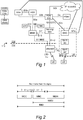
- FIG. 1 illustrates an existing network architecture for integration of a mobile telecommunications system 110 in the form of an EPS system, and a Wi-Fi access network 120.
- EPS was introduced in 3GPP Release 8 and Release 9.
- the mobile telecommunications (EPS) system 110 comprises a radio access network 112 known as E-UTRAN (Evolved Universal Terrestrial Radio Access Network) and a core network 114 known as EPC (Evolved Packet Core).
- E-UTRAN Evolved Universal Terrestrial Radio Access Network
- EPC Evolved Packet Core
- the E-UTRAN has a combined base station and radio network controller known as eNodeB.
- the EPC has units known as MME (Mobility Management Entity) and a Serving GW (Gateway).
- MME Mobility Management Entity
- S1-MME Session Management Entity
- S1-U Serving GW
- BNG Broadband Network Gateway
- Wi-Fi Alliance Hotspot 2.0 (Release 1) TS Version 1.0.0, which can be obtained from the website of the Wi-Fi Alliance at http://www.wi-fi.org/ .
- HS2.0 is primarily geared towards Wi-Fi networks.
- HS2.0 builds on IEEE 802.11u, and adds requirements on authentication mechanisms and auto-provisioning support.
- IEEE 802.11u reference is made to IEEE 802.1 1u-2011, Amendment 9: Interworking with External Networks, which can be obtained from the website http://standards.ieee.org .
- Hotspot 2.0 The momentum of Hotspot 2.0 is due to its roaming support, its mandatory security requirements and for the level of control it provides over the terminal for network discovery and selection. Even if the current release of HS2.0 is not geared towards 3GPP interworking, 3GPP operators are trying to introduce additional traffic steering capabilities, leveraging HS2.0 802.11u mechanisms. Because of the high interest of 3GPP operators, there will be a second release of HS2.0 focusing on 3GPP interworking requirements.
- the HS2.0 contains the following procedures:
- the Access Network Discovery and Selection Function is an entity defined by 3GPP for providing access discovery information as well as mobility and routing policies to the UE.
- the information and policies provided by the ANDSF may be subscriber specific.
- Access Discovery Information is used to provide access discovery information to the UE, which can assist the UE to discover available (3GPP and) non-3GPP access networks without the burden of continuous background scanning.
- ISMP Inter-System Mobility Policies
- ISRP Inter-System Routing Policies
- IMSI International Mobile Subscriber Identity
- NMSI National Mobile Subscriber Identity
- MNC Mobile Network Code
- MSIN Mobile Subscriber Identification Number
- IMEISV International Mobile station Equipment Identity and Software Version number
- IMEI International Mobile station Equipment Identity
- MSISDN MS international PSTN/ISDN number
- the permanent UE identities are only known in the EPC 114, whereas the E-UTRAN 112 is only aware of temporary UE identities.
- An example of this is the Globally Unique Temporary UE Identity (GUTI) that uniquely identifies the MME which allocated the GUTI and also identifies the UE within the MME that allocated the GUTI.
- GUTI Globally Unique Temporary UE Identity
- S-TMSI S-TMSI
- the GUTI is allocated to the UE during an Attach procedure as defined in the aforementioned 3GPP TS 23.401 (also see Figures 3A and 3B ), and the serving MME holds the association between the GUTI and the UE permanent identifier(s).
- the UE When the UE accesses a Wi-Fi network, it can be authenticated using EAP-SIM (Extensible Authentication Protocol-SIM) and EAP-AKA (Extensible Authentication Protocol-Authentication and Key Agreement) protocols. In these cases, the UE can be identified by either the full authentication Network Access Identifier (NAI) or by the fast re-authentication NAI.
- NAI Network Access Identifier
- the full authentication NAI contains the IMSI of the UE, and the fast re-authentication NAI is similar to the temporary identities used in LTE access in the sense that it is the 3GPP AAA Server that knows the relation between the fast re-authentication NAI and the full authentication NAI.
- FIGs 3A and 3B shows an overview of the attach procedure used in for instance the E-UTRAN 112 of Figure 1 .
- the attach procedure is described in detail in 3GPP TS 23.401.
- the UE is authenticated to the network in a step 5a, using credentials stored on the (U)SIM ((Universal) Subscriber Identity Module) in the UE.
- the UE will use the IMSI as an identifier of the UE subscription (and (U)SIM).
- the UE might be assigned other shorter temporary identifiers such as S-TMSI, P-TMSI, URNTI, etc.
- the MME/SGSN in the 3GPP Core Network (CN) will be aware of the IMSI associated and the mapping to temporary identifiers when the UE has an active context in the network.
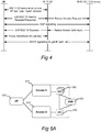
- Figure 4 shows an example procedure for a Wi-Fi-enabled UE connecting to a Wi-Fi network, such as access network 120 in Fig 1 , with a Wi-Fi Access Controller (AC).
- a Wi-Fi network such as access network 120 in Fig 1
- AC Wi-Fi Access Controller
- Other procedures may also be used depending on implementation in the UE and network.
- the EAP signalling is in this procedure used to authenticate the UE towards the network.
- the UE uses IMSI or some other certificate to identify itself towards the network.
- the current methods for integration of Wi-Fi into a 3GPP network described above do not offer good support for network-controlled Wi-Fi/3GPP access selection and service mapping, taking into consideration radio access related input parameters such as UE mobility, 3GPP/Wi-Fi cell and network load, radio link performance, etc.
- the UE context in the 3GPP radio access network (RAN) - which holds information about radio performance, UE mobility, etc. on the 3 GPP side - with the UE context in the Wi-Fi network.
- RAN radio access network
- This can then enable a network entity to take decisions whether the UE should access the Wi-Fi network or not, depending on if the UE is stationary, and/or has a good connection to the Wi-Fi AP (Access Point), etc.
- the decision can then be signaled to the UE or executed internally in the 3 GPP/Wi-Fi network (for instance to control UE admission to Wi-Fi).
- WO 2010/019848 A1 describes a network system for communicating with mobile nodes which has multiple gateways that can operate with each using a different access technology.
- the access gateways each provide an interface identifier to the mobile nodes using the same one or more keys and a hash so that different access gateways can provide the same interface identifier regardless of the access technology used.
- the access gateways can have multiple options for using keys and/or hashes to provide an interface identifier such that the method for determining the interface identifier is configurable.
- US 2011/128907 A1 provides an Access Selection Server (ASS) and a method for the same. It also provides a User Equipment (UE).
- the Access Selection Server (ASS) comprises storing means and software and is adapted for location in a communication network comprising at least one User Equipment (UE) and communication nodes.
- the ASS is also arranged to store information of all accesses for each UE in the communication network and information of overall load status of the communication network in the storing means by means of collecting information through interactions with the communication nodes, the UE and an Access Selection Server subscriber Data Base (ASS DB).
- the ASS is further arranged to communicate control messages, based on the stored information, from the ASS to the UE, thereby enabling control of multiple UE-accesses from the ASS.
- US 2010/290448 A1 relates to a method, an Access Selection Server and a communication network for network access selection.
- a basic concept may also include:
- the concept can be used together with existing methods for integrating UE Wi-Fi traffic in 3GPP networks (e.g. S2a method as seen in Figure 1 and S2b and S2c methods not shown in Figure 1 ) as well as existing authentication methods such as
- EAP-TLS Extensible Authentication Protocol-Transport Layer Security
- such a basic concept may form the basis for network-controlled access selection or service mapping as follows:
- One aspect of the present invention can therefore be summarized as a radio communication system comprising a first access network arranged to operate according to a first Radio Access Technology, a second access network arranged to operate according to a second Radio Access Technology, and a user device which is connected to said first access network and to said second access network.
- the system further comprises:
- the system is arranged to cause said access selection decision to be executed by informing said authentication node about said access selection decision in at least one of: said second access network and said user device.
- the authentication node may be arranged to identify said user device based on a user identifier provided by the user device.
- This identifier may be an International Mobile Subscriber Identity (IMSI).
- the identifier is a temporary identifier assigned to said user device in said first access network, wherein said authentication node is arranged to use the temporary identifier for retrieving a permanent identifier of said user device from a network resource in or via said first access network.
- the temporary identifier may be, for instance, a Packet Temporary Mobile Subscriber Identity (P-TMSI) or Shortened Temporary Mobile Subscriber Identity (S-IMSI).
- said user device identifier is associated with said first access network is to be construed broadly to comprise, without limitations, cases where the user device identifier is directly associated with or known to the first access network (for instance a temporary identifier like P-TMSI), as well as cases where the user device identifier is indirectly associated with the first access network (for instance in the form of a mapping between a temporary identifier like P-TMSI - which is directly known to the first access network - and a permanent identifier like IMSI, wherein the mapping is held by a network node somewhere in the radio communication system, for instance in a node in a core network coupled to the first access network).
- a temporary identifier like P-TMSI for instance a temporary identifier like P-TMSI
- IMSI permanent identifier
- the context information provided by said stand-alone query node about said user device includes a current location of said user device in said first access network.
- the RAN parameters may typically relate to one or more of the following:
- the access selection decision involves at least one of the following:
- the first access network may be part of a mobile telecommunication system compliant with, for instance, GSM, UMTS, FOMA, EPS, D-AMPS or CDMA2000.
- the first access network may for instance be capable of radio communication in accordance with GPRS/EDGE, WCDMA/HSPA, LTE/E-UTRAN, or any combination thereof, or alternatively TD-SCDMA.
- GPRS/EDGE GPRS/EDGE
- WCDMA/HSPA High Speed Packet Access
- LTE/E-UTRAN Long Term Evolution/E-UTRAN
- Other existing and future mobile telecommunication systems and radio communication technologies are however also feasible.
- the second access network may be a short-range wireless communication network compliant with, for instance, IEEE 802.11 (Wi-Fi or WLAN).
- the second access network may be of any of the types referred to above for the first access network.
- Other existing and future technologies are however also feasible, as was referred to in the background section of this document.
- the authentication node, stand-alone query node and stand-alone access selection node are to be seen as functional elements rather than structural.
- the functionalities of these three nodes may be split between and/or performed in a distributed cooperative manner by other, existing nodes in the first and second access networks, or in the user device. Some examples of this will be found in the detailed description section of this document.
- some or all of the functionalities of these three nodes may be performed by separate hardware dedicated for this purpose, such as appropriately configured computer equipment.
- Another aspect of the present invention can be summarized as a method for use in a radio communication system of the type which comprises a first access network arranged to operate according to a first Radio Access Technology, a second access network arranged to operate according to a second Radio Access Technology, and a user device which is connected to said first access network and to said second access network.
- the method comprises:
- the user device is identified based on a user identifier provided by the user device.
- This identifier may be an International Mobile Subscriber Identity (IMSI).
- IMSI International Mobile Subscriber Identity
- the identifier is a temporary identifier assigned to said user device in said first access network, and wherein the identifying of said user device further comprises using the temporary identifier for retrieving a permanent identifier of said user device from a network resource in or via said first access network.
- the context information provided by said stand-alone query node about said user device includes a current location of said user device in said first access network.
- the RAN parameters may typically relate to one or more of the following:
- the stand-alone access selection decision involves at least one of the following:
- Yet another aspect of the present invention can be summarized as a computer readable storage medium encoded with instructions that, when loaded and executed by a processor, causes performance of the method referred to above.
- Still another aspect of the present invention can be summarized as an arrangement for use in a radio communication system comprising a first access network arranged to operate according to a first Radio Access Technology and a second access network arranged to operate according to a second Radio Access Technology, wherein said arrangement comprises:
- the means for identifying a user device may be implemented by the aforementioned authentication node in the radio communication system aspect of the invention.
- the means for providing information about a context of said user device may be implemented by the aforementioned query node in the radio communication system aspect of the invention.
- the means for generating an access selection decision may be implemented by the aforementioned access selection node in the radio communication system aspect of the invention.
- the arrangement may further comprise means for causing said access selection decision to be executed in said radio communication system.
- the arrangement may further comprise means for causing performance of any functional feature of the method aspect referred to above.
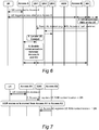
- FIG. 5A A high level functional architecture of an embodiment of the present invention is shown in Figure 5A .
- FIG. 5B A corresponding functionality is shown in Figure 5B .
- a user device 500 is connectable to a first access network 510, also referred to as Access A.
- the user device 500 is also connectable to a second access network 520, also referred to as Access B.
- the first access network 510, Access A is arranged to operate according to a first Radio Access Technology, which in the disclosed embodiments is either 3GPP WCDMA/HSPA or LTE/E-UTRAN, or WCDMA/HSPA and LTE/E-UTRAN in combination.
- the second access network 520 is arranged to operate according to a second Radio Access Technology, which in the disclosed embodiment is WiFi.
- a second Radio Access Technology which in the disclosed embodiment is WiFi.
- the user device 500 is a user equipment, UE.
- An embodiment of such a UE is illustrated in more detail as 900 in Figure 9 and will be described in more detail later.
- Other embodiments may be however be based on other Radio Access Technologies for the first and second access networks 510, 520, as has been referred to previously in this document.
- the architecture shown in Figure 5A moreover comprises an Authentication Node (AN) 530, one or more Query Nodes (QNs) 540 and an Access Selection Node (ASN) 550.
- the illustration shows that for example the QN 540 may be part of Access A or outside of Access A.
- the AN 530 may be part of Access B or outside Access B.
- the ASN 550 it is shown in Figure 5A as being outside both Access A and B. Any other alternatives are also possible, i.e. the ASN 550 may be part of Access A or Access B as well.
- the ASN 550 is distributed, such that its functionality is performed by or at more than one entity in the system.
- the communication between the AN 530 and the QN(s) 540 occurs via the ASN 550, or that the communication occurs directly between these functions.
- the authentication node AN 530 is arranged to identify the UE 500 when seeking access to the second access network 520, Access B, through a user device identifier for the UE 500, wherein this user device identifier is associated with the first access network 510, Access A.
- the query node QN 540 is arranged to provide information about a context of the UE 500 in the first access network 510, Access A, based on the user device identifier.
- the access selection node ASN 550 is arranged to generate an access selection decision for the access sought by the UE 500 to the second access network 520, Access B, based on the provided context information.
- step 630 the system is arranged to cause the access selection decision to be executed.
- Figure 5A is a logical drawing rather than a physical; hence the functions of the different entities shown in Figure 5A can be implemented in different physical units in the system.
- Access A is 3GPP WCDMA/HSPA and Access B is Wi-Fi
- the QN 540 could be communicating towards a radio network controller (RNC) in Access A, or it may be implemented as part of the RNC.
- RNC radio network controller
- the QN 540 could be communicating towards the eNodeB in the E-UTRAN 112 of Figure 1 , or it may be implemented as part of the eNodeB.
- the AN 530 may be part of for example a Wi-Fi Access Controller (AC) - such as the one shown in the Wi-Fi access network 120 of Figure 1 - or it may communicate with such a Wi-Fi AC.
- the ASN 550 could implemented as part of the Wi-Fi AC, the RNC or as a stand-alone physical node.
- the envisioned solution according to Figures 5A and 5B is a target-based network-controlled solution, where the UE by itself tries to perform access to the target access (Access B), which then triggers the network to take an access selection or services mapping decision.
- Target-based solutions do not require any UE impacts (meaning that they can be applied to existing UEs on the market).
- Target-based solutions in accordance with the present invention can however still benefit from UE impacts.
- FIG. 5C shows a schematic view of a computer readable storage medium 640 which may be used to accommodate instructions for performing the functionality of the present invention, as is generally outlined in Figure 5B .
- the computer-readable medium 640 is a memory stick, such as a Universal Serial Bus (USB) stick.
- the USB stick 640 comprises a housing 643 having an interface, such as a connector 644, and a memory chip 642.
- the memory chip 642 is a flash memory, i.e. a non-volatile data storage that can be electrically erased and reprogrammed.
- the memory chip 642 is programmed with instructions 641 that when loaded (possibly via the connector 644) into a processor will cause execution of the method.
- the processor may be at least one CPU (Central Processing Unit), DSP (Digital Signal Processor), FPGA (Field-Programmable Gate Arrays), ASIC (Application Specific Integrated Circuit) or any other electronic programmable logic device, or a combination of any such devices, adapted for executing the instructions stored on the aforementioned storage medium 640.
- a processor may act as a controller in a node in the first or second access networks (Access A, Access B).
- the instructions may be adapted for execution by several processors, possibly located in different nodes in said first and second networks, in a distributed cooperative manner, as is mentioned is other parts of this document.
- USB stick 640 in Figure 5C is merely one example of a computer-readable storage medium.
- Other examples may include compact discs, digital video discs, hard drives or other memory technologies commonly used.
- the UE If the UE supports EAP-SIM or EAP-AKA based authentication in Wi-Fi (i.e. Access B), it will (at least for initial attach) identify itself to the Wi-Fi network (internally the Wi-Fi Access Controller or some other node having the authenticator role), using the IMSI ((U)SIM-related identifier).
- Wi-Fi Wi-Fi Access Controller
- IMSI (U)SIM-related identifier
- the UE In case the UE has been previously connected to a particular access network, it might have been assigned an access-specific temporary identifier, such as 3GPP-defined S-TMSI or P-TMSI, EAP-SIM/AKA fast re-authentication NAI, etc.
- the network node responsible for the authentication needs to either have stored the permanent UE identity (e.g. IMSI received from the last time the UE was connected to the access network), or retrieve the permanent identity from another node or network resource, such as an AAA server or MME ( Figure 1 ) or Home Location Register (HLR).
- the temporary identifier is used to find the context in the other node.
- the network node responsible for the authentication in the access network needs to also retrieve the IMSI in conjunction with authentication procedure.
- the IMSI could in this case for instance be stored in an AAA-server or HLR, which also contains information about the certificate of the UE.
- the IMSI can be passed on to the node in the target access network responsible for the authentication of the UE.
- the source access network will assign to the UE an UE identity while the UE is in Access A.
- This identity can be assigned using dedicated signaling, transferred in a secure manner over the radio interface of Access A.
- the actual identity could be made up of a random temporary identifier, such as 3GPP S-TMSI, P-TMSI, or it could be an IP address which the UE also uses for communication, or some specific bit-string.
- the identity can also, in combination with UE-specific identity, also contain information which is used for internal routing in the network (such as, for instance, identity information regarding the relevant MME, RNC, Wi-Fi AC, etc). Other possible combinations of identities are also possible.
- the UE When the UE later performs access to the target access network (Access B), it will transfer the assigned identity to the target access network (Access B), which then can be used by Access B to locate the UE context in the source access network (Access A).
- the node responsible for authentication i.e. the Authentication Node (AN) 530 of the UE in the target RAT (Access B) has determined the unique identifier (e.g. IMSI) of the UE seeking the access (as described in subsection 1 above), it will initiate procedure to locate the UE context in the previous RAT (Access A).
- This procedure is achieved by querying a node or function, namely the Query Node (QN) 540, which is aware of the UE location in the previous RAT.
- This Query Node is able to map the unique identifier to a UE RAN context located either in that node or in a separate node.
- the Query Node 540 will assist the communication between the separate node and the Authentication Node 530, either by providing addressing information of the Previous RAT Node to the Authentication Node 530, or by forwarding messages between the Previous RAT Node and Authentication Node 530.
- the Authentication Node 530 can query multiple Query Nodes 540 for a given UE.
- a Query Node 540 is not aware of the location of the UE, it can either respond with a negative message to the Authentication Node 530, or it can in turn query another Query Node 540 which could know the location of the UE.
- the Query Nodes 540 can be cascaded. This procedure can be enhanced based on information in the Authentication Node 530 about the location (e.g. geo position) of the access nodes (e.g.
- the Authentication Node 530 can focus on querying Query Nodes 540 which are associated with source RAT nodes which covers the same area as the target RAT nodes (e.g. the 3GPP cells which have partially overlapping coverage with the Wi-Fi cell that the UE is accessing).
- the Query Node 540 can either be implemented together with RAT specific functions such as RNCs, Wi-Fi access controllers, MMEs, etc., or it can be a stand-alone node.
- this signaling to update the location of specific UEs could be part of normal RAT specific mobility signaling (e.g. handovers, path switch, cell update).
- the Query Node 540 can also be implemented together with the Authentication Node 530.
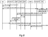
- Figure 6 shows an example of this case, where the RAN context of the UE is located in Access A (the source RAT) when the UE is attempting to access Access B (the target RAT).
- the RAT specific node will perform signaling towards the Query Nodes when the UE register in the RAT the first time, and when the UE is moving in the RAT.
- the RAT nodes can also inform the Query Node about UE specific information, such as UE capabilities, ongoing services, UE mobility states etc.
- the UE can be identified in this signaling by using a unique identifier (e.g. IMSI) or a temporary identifier assigned while the UE was in the source RAT (Access A).
- a unique identifier e.g. IMSI
- Access A a temporary identifier assigned while the UE was in the source RAT (Access A).
- Figure 7 shows an example of this case.
- the RAT specific nodes Access A1 and A2 can be for example RNCs, eNodeBs or MMEs, as described in other parts of this document.
- the ASN 550 responsible for performing access selection, and/or service mapping, decisions.
- This ASN node 550 is responsible for deciding if the UE should be accepted in the target access network (Access B) and/or if the UE should leave the source access network (Access A) or not.
- the ASN 550 node can decide if a specific service of the UE should be mapped on a specific access network among Access A or Access B.
- the Access Selection Node 550 can base this decision upon RAN related parameters provided by the source and target RATs, as well as information provided from the UE. Possible parameters include (but are not limited to) information about:
- These parameters can be sent to the ASN 550 both from Access A (source RAT) and from Access B (target RAT) in order to facilitate access selection and/or service mapping decision by the ASN 550 based on those parameters.
- the parameters can also be sent from a node outside of the source and target RATs, such as for instance by a node in a core network coupled to any of the RATs.
- the relevant information for the parameters may be held by an MME in the core network 114 coupled to the RAT 112 as seen in Figure 1 .
- the signaling to transfer these parameters to the ASN 550 can be performed as separate signaling or piggybacked on the messages used to locate the RAN context.
- the Access Selection Node 550 can be implemented together with the Authentication Node 530 and/or Query Node(s) 540, or as a stand-alone entity.
- the Access Selection Node 550 can even be implemented in the UE based on information provided by the network (e.g. from source/target RAT).
- the Access Selection Node 550 is implemented in the network, it can be implemented together with existing nodes e.g. MMEs, RNCs, Wi-Fi AP, Wi-Fi AC, eNodeB, etc.
- Figure 8 shows an example of this case. This example is based on that the signalling from the AN 530 towards the QN(s) 540 is separate from the signalling towards the ASN 550. Steps 1 to 5 are the same as in Figure 6 , and the new parts are shown as steps 6 and 7.
- the ASN 550 takes an access selection and/or service mapping decision for the access sought by the UE to the second access network (Access B, target RAT).
- the decision taken needs to be conveyed to different parts of the network depending on the decision taken, in accordance with the following:
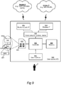
- Figure 9 illustrates a user device 900 which is connectable to first and second access networks, Access A and Access B.
- the user device 900 may implement the UE 500 according to the preceding drawings and descriptions.
- the user device 900 has a controller 950 which has the overall responsibility for controlling the operation of the user device 900.
- the controller 950 is a central processing unit (CPU), but it can alternatively be a digital signal processor (DSP), or other programmable electronic logic device such as an application-specific integrated circuit (ASIC) or field-programmable gate array (FPGA).
- the controller 950 is coupled to a memory 960 which comprises a work memory and a storage memory.
- the memory 960 may for instance be implemented in the form of RAM, EEPROM, flash memory (e.g. memory card), magnetic hard disk, or any combination thereof.
- the memory 960 is capable of storing program code which is executable by the controller 950 so as to cause performing of the terminal-side part of the functionalities as described in various parts of this document. In alternative embodiments, some or all of the terminal-side functionality may instead be performed by dedicated hardware.
- the user device 900 has a mobile network interface 952 which allows the user device 900 to communicate with the first access network, Access A.
- the mobile network interface 952 comprises an internal or external antenna as well as appropriate radio circuitry for establishing and maintaining a wireless link to a nearby base station in the first access network, Access A.
- the radio circuitry comprises a radio receiver and transmitter formed for instance by band pass filters, amplifiers, mixers, local oscillators, low pass filters, AD/DA converters, etc.
- the disclosed embodiment of the user device 900 has a wireless interface 954 which may be adapted for communication in accordance with one or more short-range wireless communication standards such as WiFi (e.g. IEEE 802.11, WLAN), Bluetooth, Near Field Communication (NFC), or Infrared Data Association (IrDA).
- a serial interface such as USB may allow the user device 900 to communicate over a serial cable with for instance a personal computer. Such interfaces may be absent in other embodiments.
- Communication protocol stacks 958 are provided to allow communication via any of the interfaces 952 and 954.
- a user interface 962 allows a user 2 to interact with the user device 900.
- the user interface 962 includes display means, such as at least one LCD display, as well as input means for the user.
- the input means may e.g. include a keypad with alphanumeric keys and/or other keys such as arrow keys (navigation keys) and functional keys (soft keys), and/or a joystick, touch pad, rotator, jog dial, etc.
- the display means and input means may be jointly realized by a touch-sensitive display in some embodiments.
- the user interface 962 typically also involves a loudspeaker and a microphone.
- the user device 900 may also be provided with other well-known components, such as power switch, battery, charger interface, accessory interface, and volume controls; such elements are however not indicated in Figure 9 for the sake of brevity.
- the user device 900 has a (U)SIM reader capable of accessing a (U)SIM card 902.
- the (U)SIM card 902 comprises electronic circuitry 903 which constitutes a local (U)SIM controller 903a and a memory 903b.
- the memory 903b has a memory area 904 for storing the subscriber identity in the form of an IMSI number.
- a temporary UE identity such as P-TMSI or S-TMSI
- a non-IMSI UE identifier can be read from the (U)SIM memory 903b or from the memory 960 and be presented by the user device 900 to the access network (Access B or Access A) which it is presently seeking access to.
- Figure 10 is a schematic block diagram illustrating an arrangement 1090 for use in a radio communication system 1110, wherein the radio communication system 1110 comprises a first access network 1010 arranged to operate according to a first Radio Access Technology, and a second access network 1020 arranged to operate according to a second Radio Access Technology.
- the first access network 1010 may, for instance, be the access network referred to as Access A and/or 510 in the embodiments described above.
- the second access network 1020 may, for instance, be the access network referred to as Access B or 520 in the embodiments described above.
- the arrangement 1090 comprises means 1030 for identifying a user device 1000, when seeking access to the second access network 1020, through a user device identifier for the user device, the user device identifier being associated with the first access network 1010.
- the user device 1000 may, for instance, be the device referred to as UE, 500 or 900 in the embodiments described above.
- the means 1030 may, for instance, be the authentication node referred to as AN or 530 in the embodiments described above, and the means 1030 may, for instance, be adapted to perform the step 600 in Figure 5B .
- the arrangement 1090 further comprises means 1040 for providing information about a context of the user device 1000 in the first access network 1010 based on the user device identifier.
- the means 1040 may, for instance, be the query node referred to as QN or 540 in the embodiments described above, and the means 1040 may, for instance, be adapted to perform the step 610 in Figure 5B .
- the arrangement 1090 also comprises means 1050 for generating an access selection decision for the access sought by the user device 1000 to the second access network 1020 based on the provided context information.
- the means 1050 may, for instance, be the access selection node referred to as ASN or 550 in the embodiments described above, and the means 1050 may, for instance, be adapted to perform the step 620 in Figure 5B .
- the arrangement 1090 may also comprise means 1060 for causing the access selection decision to be executed in the radio communication system 1110.
- the means 1060 may, for instance, be adapted to perform the step 630 in Figure 5B , and it may, for instance, be adapted to cause the access selection decision to be executed by appropriately informing the relevant element(s) in the radio communication system 1110 about the access selection decision taken, as has been described above under subsection 4 in this detailed description section.
- the arrangement 1090 may further comprise means (collectively referred to as 1070 in Figure 10 ), for performing any or all of the additional functionality described for the embodiments above and, particularly, any steps of the method referred to in the summary section of this document.
Landscapes
- Engineering & Computer Science (AREA)
- Computer Security & Cryptography (AREA)
- Computer Networks & Wireless Communication (AREA)
- Signal Processing (AREA)
- Mobile Radio Communication Systems (AREA)
Claims (17)
- Système de radiocommunication comprenant un premier réseau d'accès (Accès A ; 510) conçu pour fonctionner selon une première technologie d'accès radio, un second réseau d'accès (Accès B ; 520) conçu pour fonctionner selon une seconde technologie d'accès radio, et un dispositif utilisateur (UE ; 500 ; 900) qui est connecté audit premier réseau d'accès (Accès A ; 510) et déclenche une tentative d'accès audit second réseau d'accès (Accès B ; 520), dans lequel ledit système comprend en outre :un nœud d'authentification (AN ; 530) conçu pour identifier (8:3) ledit dispositif utilisateur (UE ; 500 ; 900), lorsqu'il cherche à accéder audit second réseau d'accès (Accès B ; 520), via un identifiant de dispositif utilisateur pour ledit dispositif utilisateur (UE ; 500 ; 900), dans lequel ledit identifiant de dispositif utilisateur est associé audit premier réseau d'accès (Accès A ; 510) ;ledit nœud d'authentification (AN ; 530) étant en outre conçu pour localiser un contexte dudit dispositif utilisateur (UE ; 500 ; 900) dans ledit premier réseau d'accès (Accès A ; 510) sur la base dudit identifiant de dispositif utilisateur, en interrogeant un nœud d'interrogation autonome (QN ; 540) qui est conscient du contexte dudit dispositif utilisateur (UE ; 500 ; 900) ;ledit nœud d'interrogation autonome (QN ; 540) étant conçu pour recevoir une signalisation, à partir dudit premier réseau d'accès (Accès A ; 510), concernant les informations spécifiques au contexte et à l'UE dudit dispositif utilisateur (UE ; 500 ; 900) ;ledit nœud d'interrogation autonome (QN ; 540) étant en outre conçu pour fournir des informations (8:5), à un nœud de sélection d'accès autonome (ASN ; 550), concernant les informations spécifiques au contexte et à l'UE dudit dispositif utilisateur (UE ; 500 ; 900) dans ledit premier réseau d'accès (Accès A ; 510) sur la base dudit identifiant de dispositif utilisateur ;ledit nœud d'interrogation autonome (QN ; 540) étant en outre conçu pour fournir des paramètres associés à un réseau d'accès radio, RAN, du premier réseau d'accès (Accès A ; 510) audit nœud de sélection d'accès autonome (ASN ; 550) et audit nœud d'authentification (AN ; 530) en outre conçu pour fournir des paramètres de réseau d'accès radio, RAN, du second réseau d'accès (Accès B ; 520) audit nœud de sélection d'accès autonome (ASN ; 500) ; etledit nœud de sélection d'accès autonome (ASN ; 550) étant conçu pour générer une décision de sélection d'accès pour l'accès recherché par ledit dispositif utilisateur (UE ; 500 ; 900) audit second réseau d'accès (Accès B ; 520) sur la base d'au moins les uns parmi les éléments suivants : les informations de contexte fournies dudit dispositif utilisateur (UE ; 500 ; 900), les paramètres associés au RAN fournis et les informations spécifiques à l'UE fournies à partir dudit dispositif utilisateur (UE ; 500 ; 900), dans lequel ledit nœud de sélection d'accès autonome (ASN ; 550) est conçu pour informer au moins l'un des éléments suivants :
ledit nœud d'authentification (AN ; 530) et ledit dispositif utilisateur (UE ; 500 ; 900) concernant ladite décision de sélection d'accès. - Système selon la revendication 1, dans lequel ledit nœud d'authentification (AN ; 530) est conçu pour identifier ledit dispositif utilisateur (UE ; 500 ; 900) sur la base d'un identifiant utilisateur fourni par ledit dispositif utilisateur (UE ; 500 ; 900).
- Système selon la revendication 2, dans lequel ledit identifiant utilisateur est une identité internationale d'abonné mobile, IMSI.
- Système selon la revendication 2, dans lequel ledit identifiant utilisateur est un identifiant temporaire attribué audit dispositif utilisateur (UE ; 500 ; 900) dans ledit premier réseau d'accès (Accès A ; 510), et dans lequel ledit nœud d'authentification (AN ; 530) est conçu pour utiliser l'identifiant temporaire afin de récupérer un identifiant permanent dudit dispositif utilisateur (UE ; 500 ; 900) à partir d'une ressource réseau dans ou via ledit premier réseau d'accès (Accès A ; 510).
- Système selon l'une quelconque des revendications 1 à 4, dans lequel les informations de contexte fournies par ledit nœud d'interrogation (QN ; 540) concernant ledit dispositif utilisateur (UE ; 500 ; 900) comportent un emplacement actuel dudit dispositif utilisateur (UE ; 500 ; 900) dans ledit premier réseau d'accès (Accès A ; 510).
- Système selon la revendication 1, dans lequel lesdits paramètres associés au RAN concernent un ou plusieurs des éléments suivants :des données de mobilité concernant ledit dispositif utilisateur (UE ; 500 ; 900),une charge de travail pour un point d'accès actuel dudit dispositif utilisateur (UE ; 500 ; 900) dans ledit premier réseau d'accès (Accès A ; 510),une charge de travail pour un point d'accès dans ledit second réseau d'accès (Accès B ; 520) auquel ledit dispositif utilisateur (UE ; 500 ; 900) cherche à accéder,une charge de réseau de transport dans l'un ou l'autre desdits premier (Accès A ; 510) ou second (Accès B ; 520) réseaux d'accès, des performances de liaison radio pour ledit équipement utilisateur (UE ; 500 ; 900) dans ledit premier réseau d'accès (Accès A ; 510),des limitations spécifiques à la technologie d'accès radio dans l'un ou l'autre desdits premier (Accès A ; 510) ou second (Accès B ; 520) réseaux d'accès,des services en cours utilisés par ledit dispositif utilisateur (UE ; 500 ; 900),des capacités dudit dispositif utilisateur (UE ; 500 ; 900) pour lesdites première (Accès A ; 510) ou seconde (Accès B ; 520) technologies d'accès radio, etun profil d'abonnement d'un utilisateur final (2) associé audit dispositif utilisateur (UE ; 500 ; 900).
- Système selon l'une quelconque des revendications 1 à 6, dans lequel ladite décision de sélection d'accès implique au moins l'un des éléments suivants :la connexion dudit dispositif utilisateur (UE ; 500 ; 900) audit second réseau d'accès (Accès B ; 520),la déconnexion dudit dispositif utilisateur (UE ; 500 ; 900) dudit premier réseau d'accès (Accès A ; 510),la mise en correspondance d'un premier service dudit dispositif utilisateur (UE ; 500 ; 900) avec ledit premier réseau d'accès (Accès A ; 510) et d'un second service dudit dispositif utilisateur (UE ; 500 ; 900) avec ledit second réseau d'accès (Accès B ; 520), etle maintien de la connexion pour ledit dispositif utilisateur (UE ; 500 ; 900) avec ledit premier réseau d'accès (Accès A ; 510) .
- Système selon l'une quelconque des revendications 1 à 7, dans lequel ledit premier réseau d'accès (Accès A ; 510) fait partie d'un système de télécommunication mobile conforme aux normes GSM, UMTS, FOMA, LTE, D-AMPS ou CDMA2000.
- Système selon l'une quelconque des revendications 1 à 8, dans lequel ledit second réseau d'accès (Accès B ; 520) est un réseau de communication sans fil à courte portée conforme à la norme IEEE 802.11 (Wi-Fi ou WLAN).
- Procédé destiné à être utilisé dans un système de radiocommunication du type qui comprend un premier réseau d'accès (Accès A ; 510) conçu pour fonctionner selon une première technologie d'accès radio, un second réseau d'accès (Accès B ; 520) conçu pour fonctionner selon une seconde technologie d'accès radio, et un dispositif utilisateur (UE ; 500 ; 900) qui est connecté audit premier réseau d'accès (Accès A ; 510) et déclenche une tentative d'accès audit second réseau d'accès (Accès B ; 520), dans lequel ledit procédé comprend :l'identification (600 ; (8:3)), par un nœud d'authentification (AN ; 530) dans ledit second réseau d'accès (Accès B ; 520), dudit dispositif utilisateur (UE ; 500 ; 900), lorsqu'il cherche à accéder audit second réseau d'accès (Accès B ; 520), via un identifiant de dispositif utilisateur pour ledit dispositif utilisateur (UE ; 500 ; 900), dans lequel ledit identifiant de dispositif utilisateur est associé audit premier réseau d'accès (Accès A ; 510) ;la localisation, par ledit nœud d'authentification (AN ; 530), d'un contexte dudit dispositif utilisateur (UE ; 500 ; 900) dans ledit premier réseau d'accès (Accès A ; 510) sur la base dudit identifiant de dispositif utilisateur, en interrogeant un nœud d'interrogation autonome (QN ; 540) qui est conscient du contexte dudit dispositif utilisateur (UE ; 500 ; 900) ;la réception, par ledit nœud d'interrogation autonome (QN ; 540), d'une signalisation, à partir dudit premier réseau d'accès (Accès A ; 510), concernant les informations spécifiques au contexte et à l'UE dudit dispositif utilisateur (UE ; 500 ; 900) ;la fourniture (610 ; (8:5)), par ledit nœud d'interrogation autonome (QN ; 540), d'informations, à un nœud de sélection d'accès autonome (ASN ; 550), concernant les informations spécifiques au contexte et à l'UE dudit dispositif utilisateur (UE ; 500 ; 900) dans ledit premier réseau d'accès (Accès A ; 510) sur la base dudit identifiant de dispositif utilisateur ; la fourniture, par ledit nœud d'interrogation autonome (QN ; 540), de paramètres associés à un réseau d'accès radio, RAN, du premier réseau d'accès (Accès A ; 510) audit nœud de sélection d'accès autonome (ASN ; 550) ;et ledit nœud d'authentification (AN ; 530) en outre conçu pour fournir des paramètres de réseau d'accès radio, RAN, du second réseau d'accès (Accès B ; 520) audit nœud de sélection d'accès autonome (ASN ; 500) ;la génération (620) d'une décision de sélection d'accès pour l'accès recherché par ledit dispositif utilisateur (UE ; 500 ; 900) audit second réseau d'accès (Accès B ; 520) par un nœud autonome (ASN ; 550) sur la base d'au moins les uns parmi les éléments suivants : les informations de contexte fournies dudit dispositif utilisateur (UE ; 500 ; 900), les paramètres associés au RAN fournis et les informations spécifiques à l'UE fournies à partir dudit dispositif utilisateur (UE ; 500 ; 900),le fait d'entraîner (630), par ledit nœud de sélection d'accès autonome (ASN ; 550), l'exécution de ladite décision de sélection d'accès en informant au moins l'un des éléments suivants : ledit nœud d'authentification (AN ; 530) et ledit dispositif utilisateur (UE ; 500 ; 900) concernant ladite décision de sélection d'accès.
- Procédé selon la revendication 10, dans lequel ledit dispositif utilisateur (UE ; 500 ; 900) est identifié sur la base d'un identifiant utilisateur fourni par ledit dispositif utilisateur (UE ; 500 ; 900).
- Procédé selon la revendication 11, dans lequel ledit identifiant utilisateur est une identité internationale d'abonné mobile, IMSI.
- Procédé selon la revendication 11, dans lequel ledit identifiant utilisateur est un identifiant temporaire attribué audit dispositif utilisateur (UE ; 500 ; 900) dans ledit premier réseau d'accès (Accès A ; 510), et dans lequel l'identification dudit dispositif utilisateur comprend en outre l'utilisation de l'identifiant temporaire afin de récupérer un identifiant permanent dudit dispositif utilisateur (UE ; 500 ; 900) à partir d'une ressource réseau dans ou via ledit premier réseau d'accès (Accès A ; 510).
- Procédé selon l'une quelconque des revendications 10 à 13, dans lequel les informations de contexte fournies par ledit nœud d'interrogation (QN ; 540) concernant ledit dispositif utilisateur (UE ; 500 ; 900) comportent un emplacement actuel dudit dispositif utilisateur (UE ; 500 ; 900) dans ledit premier réseau d'accès (Accès A ; 510).
- Procédé selon la revendication 10, dans lequel lesdits paramètres associés au RAN concernent un ou plusieurs des éléments suivants :des données de mobilité concernant ledit dispositif utilisateur (UE ; 500 ; 900),une charge de travail pour un point d'accès actuel dudit dispositif utilisateur (UE ; 500 ; 900) dans ledit premier réseau d'accès (Accès A ; 510),une charge de travail pour un point d'accès dans ledit second réseau d'accès (Accès B ; 520) auquel ledit dispositif utilisateur cherche à accéder,une charge de réseau de transport dans l'un ou l'autre desdits premier (Accès A ; 510) ou second (Accès B ; 520) réseaux d'accès, des performances de liaison radio pour ledit équipement utilisateur (UE ; 500 ; 900) dans ledit premier réseau d'accès (Accès A ; 510),des limitations spécifiques à la technologie d'accès radio dans l'un ou l'autre desdits premier (Accès A ; 510) ou second (Accès B ; 520) réseaux d'accès,des services en cours utilisés par ledit dispositif utilisateur (UE ; 500 ; 900),des capacités dudit dispositif utilisateur (UE ; 500 ; 900) pour lesdites première (Accès A ; 510) ou seconde (Accès B ; 520) technologies d'accès radio, etun profil d'abonnement d'un utilisateur final (2) associé audit dispositif utilisateur (UE ; 500 ; 900).
- Procédé selon l'une quelconque des revendications 10 à 15, dans lequel ladite décision de sélection d'accès implique au moins l'un des éléments suivants :la connexion dudit dispositif utilisateur (UE ; 500 ; 900) audit second réseau d'accès (Accès B ; 520),la déconnexion dudit dispositif utilisateur (UE ; 500 ; 900) dudit premier réseau d'accès (Accès A ; 510),la mise en correspondance d'un premier service dudit dispositif utilisateur (UE ; 500 ; 900) avec ledit premier réseau d'accès (Accès A ; 510) et d'un second service dudit dispositif utilisateur (UE ; 500 ; 900) avec ledit second réseau d'accès (Accès B ; 520), etle maintien de la connexion pour ledit dispositif utilisateur (UE ; 500 ; 900) avec ledit premier réseau d'accès (Accès A ; 510) .
- Support de stockage lisible par ordinateur (640) codé avec des instructions (641) qui, lorsqu'elles sont chargées et exécutées par un processeur, entraînent l'exécution du procédé selon l'une quelconque des revendications 10 à 16.
Applications Claiming Priority (2)
| Application Number | Priority Date | Filing Date | Title |
|---|---|---|---|
| US201261644040P | 2012-05-08 | 2012-05-08 | |
| PCT/SE2012/051007 WO2013169161A1 (fr) | 2012-05-08 | 2012-09-24 | Système de radiocommunication, et procédé et agencement destinés à être utilisés dans un système de radiocommunication |
Publications (3)
| Publication Number | Publication Date |
|---|---|
| EP2848044A1 EP2848044A1 (fr) | 2015-03-18 |
| EP2848044A4 EP2848044A4 (fr) | 2016-03-02 |
| EP2848044B1 true EP2848044B1 (fr) | 2019-11-13 |
Family
ID=49551054
Family Applications (1)
| Application Number | Title | Priority Date | Filing Date |
|---|---|---|---|
| EP12876385.1A Active EP2848044B1 (fr) | 2012-05-08 | 2012-09-24 | Système de radiocommunication, et procédé et agencement destinés à être utilisés dans un système de radiocommunication |
Country Status (3)
| Country | Link |
|---|---|
| US (2) | US8942763B2 (fr) |
| EP (1) | EP2848044B1 (fr) |
| WO (1) | WO2013169161A1 (fr) |
Cited By (2)
| Publication number | Priority date | Publication date | Assignee | Title |
|---|---|---|---|---|
| US12219350B2 (en) | 2022-03-03 | 2025-02-04 | T-Mobile Usa, Inc. | Enabling peer-to-peer authentication between at least two mobile devices associated with one or more wireless telecommunication networks |
| US12425461B2 (en) | 2023-03-03 | 2025-09-23 | T-Mobile Usa, Inc. | Enabling a first mobile device associated with a wireless telecommunication network to receive assistance from a second mobile device in a shared web page |
Families Citing this family (20)
| Publication number | Priority date | Publication date | Assignee | Title |
|---|---|---|---|---|
| CN103517360B (zh) * | 2012-06-25 | 2017-04-19 | 华为终端有限公司 | 切换方法、系统及设备 |
| WO2014015486A1 (fr) * | 2012-07-25 | 2014-01-30 | 华为技术有限公司 | Procédé de dérivation de données, dispositif de transmission de données et dispositif de nœud de dérivation |
| US10104540B2 (en) | 2013-01-23 | 2018-10-16 | Qualcomm Incorporated | Determining to use multi-RAN interworking by correlating different RAN identifiers |
| US9084147B2 (en) * | 2013-05-08 | 2015-07-14 | Qualcomm Incorporated | Parallel registration to offload PLMN with single SIM |
| CN104144473B (zh) * | 2013-05-09 | 2019-12-20 | 中兴通讯股份有限公司 | 一种选择可用接入网络的方法及用户设备 |
| US9980192B2 (en) | 2014-02-21 | 2018-05-22 | Telefonaktiebolaget L M Ericsson (Publ) | Traffic steering between WLAN and cellular networks |
| EP3114865B1 (fr) * | 2014-03-06 | 2022-07-20 | Vodafone GmbH | Utilisation de services d'un réseau central de communications par paquets entre terminaux mobiles |
| CN105307173A (zh) * | 2014-06-17 | 2016-02-03 | 中兴通讯股份有限公司 | 通信网络架构、基于通信网络架构的接入认证方法及系统 |
| US10299120B2 (en) | 2014-06-18 | 2019-05-21 | Telefonaktiebolaget Lm Ericsson (Publ) | Methods and arrangements for identification of user equipments for authentication purposes |
| CN107079358B (zh) * | 2014-09-30 | 2020-05-29 | 诺基亚技术有限公司 | 用于通过信号传送标识符的方法和装置 |
| KR101961301B1 (ko) | 2015-06-05 | 2019-03-25 | 콘비다 와이어리스, 엘엘씨 | 통합된 스몰 셀 및 wi-fi 네트워크를 위한 통합 인증 |
| US10009329B2 (en) | 2015-06-23 | 2018-06-26 | Microsoft Technology Licensing, Llc | Learned roving authentication profiles |
| EP3160176B1 (fr) * | 2015-10-19 | 2019-12-11 | Vodafone GmbH | Usage d'un service d'un réseau central à commutation de paquets mobile sans avoir une carte sim |
| CN107534917B (zh) * | 2015-12-31 | 2020-06-02 | 华为技术有限公司 | 一种主从型网络中的切换方法、主设备、从设备和系统 |
| CN107295610B (zh) * | 2016-04-01 | 2019-12-20 | 电信科学技术研究院 | 一种网络接入方法、相关设备和系统 |
| CN107734573B (zh) * | 2016-08-12 | 2020-08-07 | 华为技术有限公司 | 切换方法、基站及通信系统 |
| WO2018119119A1 (fr) * | 2016-12-20 | 2018-06-28 | Intel IP Corporation | Dispositifs pour une commutation entre une technologie d'accès radio lte et une technologie d'accès radio nr durant une transition d'un état inactif à un état actif |
| WO2019068832A1 (fr) * | 2017-10-04 | 2019-04-11 | Telefonaktiebolaget Lm Ericsson (Publ) | Identificateurs dans un système de communication sans fil |
| US10499357B1 (en) | 2018-08-09 | 2019-12-03 | Nec Corporation | Method and system for transmission of SUSI in the NAS procedure |
| GB201905871D0 (en) * | 2019-04-26 | 2019-06-12 | Nordic Semiconductor Asa | LTE cellular netwrork apparatus and methods |
Family Cites Families (22)
| Publication number | Priority date | Publication date | Assignee | Title |
|---|---|---|---|---|
| US7027433B2 (en) * | 2001-06-20 | 2006-04-11 | Nokia Corporation | Routing a call between different types of networks |
| US7002942B2 (en) * | 2001-08-02 | 2006-02-21 | Motorola, Inc. | Method and apparatus for communicating information by splitting information among a plurality of proximal units |
| US7917152B2 (en) * | 2003-06-27 | 2011-03-29 | Nokia Corporation | Enhanced fast handover procedures |
| CA2559268A1 (fr) * | 2004-03-12 | 2005-09-29 | Interdigital Technology Corporation | Procede et systemes destines a commuter une technologie d'acces radio entre systemes de communication sans fil avec une unite d'emission / reception sans fil multimodale |
| KR101268578B1 (ko) * | 2005-08-26 | 2013-05-28 | 한국전자통신연구원 | 범용 이동 통신시스템망과 무선 근거리 통신망과의 서비스연속성을 위한 장치 및 방법 |
| US20070135121A1 (en) * | 2005-12-08 | 2007-06-14 | Electronics And Telecommunications Research Institute | User and service mobility support system and method in ubiquitous environment |
| US8433804B2 (en) * | 2006-01-13 | 2013-04-30 | At&T Mobility Ii Llc | Dynamic event server subsystem utilizing session initiation protocol |
| EP1885141B1 (fr) | 2006-08-02 | 2012-05-16 | Research In Motion Limited | Support d'une sélection du système d'accès radio par des stations portables multimodes |
| US7924793B2 (en) * | 2006-11-20 | 2011-04-12 | At&T Intellectual Property I, L.P. | Methods and apparatus to manage bandwidth in a wireless network |
| US8347361B2 (en) * | 2006-12-14 | 2013-01-01 | Mosaid Technologies Incorporated | Distributed network management hierarchy in a multi-station communication network |
| EP2137940B1 (fr) * | 2007-04-06 | 2012-05-16 | Interdigital Technology Corporation | Procédé et appareil pour identifier des capacités de protocole de réseau mobile |
| US9584622B2 (en) | 2007-08-23 | 2017-02-28 | Telefonaktiebolaget Lm Ericsson (Publ) | Method for network controlled access selection |
| EP2235969A4 (fr) * | 2008-01-15 | 2014-01-08 | Ericsson Telefon Ab L M | Pré-lecture de données d'entrée pour une sélection de réseau d'accès |
| WO2009127238A1 (fr) * | 2008-04-18 | 2009-10-22 | Telefonaktiebolaget Lm Ericsson (Publ) | Sélection de réseau d'accès dans un environnement à réseaux d'accès multiples |
| US8243725B2 (en) * | 2008-08-13 | 2012-08-14 | Interdigital Patent Holdings, Inc. | Maintaining circuit switched continuity in an enhanced universal terrestrial radio access network |
| US8238877B2 (en) | 2008-08-14 | 2012-08-07 | Cisco Technology, Inc. | Access technology independent identifier generation |
| US20100094938A1 (en) * | 2008-10-10 | 2010-04-15 | Nicolas Le Scouarnec | Method of transmitting data between peerss by selecting a network according to at least one criterion and associated management device and communication equipment |
| US8903390B2 (en) | 2009-05-13 | 2014-12-02 | Qualcomm Incorporated | Provisioning single-mode and multimode system selection parameters and service management |
| US8942167B2 (en) * | 2009-05-14 | 2015-01-27 | Avaya Inc. | Methods, apparatus and computer readable medium for seamless internet protocol multicast connectivity in unified networks |
| KR101738497B1 (ko) * | 2009-06-30 | 2017-08-28 | 필립스 라이팅 홀딩 비.브이. | 제어가능한 조명 네트워크들과의 상호작용을 관리하기 위한 시스템들 및 방법들 |
| US9295089B2 (en) * | 2010-09-07 | 2016-03-22 | Interdigital Patent Holdings, Inc. | Bandwidth management, aggregation and internet protocol flow mobility across multiple-access technologies |
| US8472919B1 (en) * | 2011-09-28 | 2013-06-25 | Cellco Partnership | Network based technique for obtaining operator identifier for mobile devices |
-
2012
- 2012-09-24 EP EP12876385.1A patent/EP2848044B1/fr active Active
- 2012-09-24 US US13/697,767 patent/US8942763B2/en active Active
- 2012-09-24 WO PCT/SE2012/051007 patent/WO2013169161A1/fr not_active Ceased
-
2014
- 2014-12-16 US US14/571,584 patent/US20150099488A1/en not_active Abandoned
Non-Patent Citations (1)
| Title |
|---|
| None * |
Cited By (2)
| Publication number | Priority date | Publication date | Assignee | Title |
|---|---|---|---|---|
| US12219350B2 (en) | 2022-03-03 | 2025-02-04 | T-Mobile Usa, Inc. | Enabling peer-to-peer authentication between at least two mobile devices associated with one or more wireless telecommunication networks |
| US12425461B2 (en) | 2023-03-03 | 2025-09-23 | T-Mobile Usa, Inc. | Enabling a first mobile device associated with a wireless telecommunication network to receive assistance from a second mobile device in a shared web page |
Also Published As
| Publication number | Publication date |
|---|---|
| EP2848044A1 (fr) | 2015-03-18 |
| WO2013169161A1 (fr) | 2013-11-14 |
| US8942763B2 (en) | 2015-01-27 |
| US20150099488A1 (en) | 2015-04-09 |
| US20140051393A1 (en) | 2014-02-20 |
| EP2848044A4 (fr) | 2016-03-02 |
Similar Documents
| Publication | Publication Date | Title |
|---|---|---|
| US8942763B2 (en) | Radio communication system, method and arrangement for use in a radio communication system | |
| US8060084B2 (en) | Network selection scheme using a roaming broker (RB) | |
| US12160757B2 (en) | Method and device for information transmission | |
| US9264450B2 (en) | Method of seamless policy based network discovery, selection and switching | |
| EP4192120B1 (fr) | Architecture de reseau permettant a un terminal mobile de se déplacer dans un reseau local sans fil | |
| US7447502B2 (en) | Scheme for providing regulatory compliance in performing network selection in a foreign country | |
| EP2853117B1 (fr) | Station mobile et point d'accès sans fil et leurs procédés dans un réseau de communication sans fil | |
| EP2727432B1 (fr) | Procédés et appareil pour de multiples connexions de données en paquets | |
| US10412666B2 (en) | UE accessibility indication for WI-FI integration in RAN | |
| JP6105639B2 (ja) | ネットワーク間サービス選択のためのシステムおよび方法 | |
| CN111404814B (zh) | 一种数据传输的方法及通信装置 | |
| CN111133832B (zh) | 由用户设备利用数据服务的系统和方法 | |
| EP2850878B1 (fr) | Point d'accès sans fil connecté à deux réseaux de communication | |
| EP2286619B1 (fr) | PROCÉDÉ DE COMMANDE DE LA SÉLECTION DE RÉSEAU PAR L'OPÉRATEUR DE RATTACHEMENT D'UN ÉQUIPEMENT UTILISATEUR DOUBLE& xA;& xA;PROCÉDÉ DE COMMANDE DE LA SÉLECTION DE RÉSEAU PAR L'OPÉRATEUR DU RÉSEAU LOCAL DE L'ÉQUIPEMENT UTILISATEUR EN DOUBLE-MODE AYANT DES CAPACITÉS D'ACCÈS AUX RÉSEAU MOBILE ET FIXE SANS FIL | |
| US20240340834A1 (en) | Establishing a Multiple Access Connection | |
| CN101800930A (zh) | 终端重定向方法和无线通讯方法 | |
| KR102484072B1 (ko) | 무선 통신 방법, 단말기 디바이스 및 칩 | |
| US10136377B1 (en) | Mobile device handoff optimization | |
| CN118612712A (zh) | 通信方法及通信装置 | |
| HK1096815A (en) | System and method for providing network advertisement information via a network advertisement broker |
Legal Events
| Date | Code | Title | Description |
|---|---|---|---|
| PUAI | Public reference made under article 153(3) epc to a published international application that has entered the european phase |
Free format text: ORIGINAL CODE: 0009012 |
|
| 17P | Request for examination filed |
Effective date: 20140929 |
|
| AK | Designated contracting states |
Kind code of ref document: A1 Designated state(s): AL AT BE BG CH CY CZ DE DK EE ES FI FR GB GR HR HU IE IS IT LI LT LU LV MC MK MT NL NO PL PT RO RS SE SI SK SM TR |
|
| AX | Request for extension of the european patent |
Extension state: BA ME |
|
| DAX | Request for extension of the european patent (deleted) | ||
| RA4 | Supplementary search report drawn up and despatched (corrected) |
Effective date: 20160202 |
|
| RIC1 | Information provided on ipc code assigned before grant |
Ipc: H04W 48/18 20090101AFI20160127BHEP Ipc: H04W 92/02 20090101ALI20160127BHEP Ipc: H04W 88/06 20090101ALN20160127BHEP Ipc: H04W 84/12 20090101ALN20160127BHEP |
|
| STAA | Information on the status of an ep patent application or granted ep patent |
Free format text: STATUS: EXAMINATION IS IN PROGRESS |
|
| 17Q | First examination report despatched |
Effective date: 20190321 |
|
| REG | Reference to a national code |
Ref country code: DE Ref legal event code: R079 Ref document number: 602012065730 Country of ref document: DE Free format text: PREVIOUS MAIN CLASS: H04W0048160000 Ipc: H04W0048180000 |
|
| GRAP | Despatch of communication of intention to grant a patent |
Free format text: ORIGINAL CODE: EPIDOSNIGR1 |
|
| STAA | Information on the status of an ep patent application or granted ep patent |
Free format text: STATUS: GRANT OF PATENT IS INTENDED |
|
| RIC1 | Information provided on ipc code assigned before grant |
Ipc: H04W 48/18 20090101AFI20190523BHEP Ipc: H04W 92/02 20090101ALI20190523BHEP Ipc: H04W 88/06 20090101ALN20190523BHEP Ipc: H04W 12/08 20090101ALN20190523BHEP Ipc: H04W 84/12 20090101ALN20190523BHEP |
|
| INTG | Intention to grant announced |
Effective date: 20190612 |
|
| GRAS | Grant fee paid |
Free format text: ORIGINAL CODE: EPIDOSNIGR3 |
|
| GRAA | (expected) grant |
Free format text: ORIGINAL CODE: 0009210 |
|
| STAA | Information on the status of an ep patent application or granted ep patent |
Free format text: STATUS: THE PATENT HAS BEEN GRANTED |
|
| AK | Designated contracting states |
Kind code of ref document: B1 Designated state(s): AL AT BE BG CH CY CZ DE DK EE ES FI FR GB GR HR HU IE IS IT LI LT LU LV MC MK MT NL NO PL PT RO RS SE SI SK SM TR |
|
| REG | Reference to a national code |
Ref country code: CH Ref legal event code: EP Ref country code: AT Ref legal event code: REF Ref document number: 1203015 Country of ref document: AT Kind code of ref document: T Effective date: 20191115 |
|
| REG | Reference to a national code |
Ref country code: DE Ref legal event code: R096 Ref document number: 602012065730 Country of ref document: DE |
|
| REG | Reference to a national code |
Ref country code: IE Ref legal event code: FG4D |
|
| REG | Reference to a national code |
Ref country code: NL Ref legal event code: MP Effective date: 20191113 |
|
| REG | Reference to a national code |
Ref country code: LT Ref legal event code: MG4D |
|
| PG25 | Lapsed in a contracting state [announced via postgrant information from national office to epo] |
Ref country code: PT Free format text: LAPSE BECAUSE OF FAILURE TO SUBMIT A TRANSLATION OF THE DESCRIPTION OR TO PAY THE FEE WITHIN THE PRESCRIBED TIME-LIMIT Effective date: 20200313 Ref country code: ES Free format text: LAPSE BECAUSE OF FAILURE TO SUBMIT A TRANSLATION OF THE DESCRIPTION OR TO PAY THE FEE WITHIN THE PRESCRIBED TIME-LIMIT Effective date: 20191113 Ref country code: GR Free format text: LAPSE BECAUSE OF FAILURE TO SUBMIT A TRANSLATION OF THE DESCRIPTION OR TO PAY THE FEE WITHIN THE PRESCRIBED TIME-LIMIT Effective date: 20200214 Ref country code: FI Free format text: LAPSE BECAUSE OF FAILURE TO SUBMIT A TRANSLATION OF THE DESCRIPTION OR TO PAY THE FEE WITHIN THE PRESCRIBED TIME-LIMIT Effective date: 20191113 Ref country code: LT Free format text: LAPSE BECAUSE OF FAILURE TO SUBMIT A TRANSLATION OF THE DESCRIPTION OR TO PAY THE FEE WITHIN THE PRESCRIBED TIME-LIMIT Effective date: 20191113 Ref country code: BG Free format text: LAPSE BECAUSE OF FAILURE TO SUBMIT A TRANSLATION OF THE DESCRIPTION OR TO PAY THE FEE WITHIN THE PRESCRIBED TIME-LIMIT Effective date: 20200213 Ref country code: NL Free format text: LAPSE BECAUSE OF FAILURE TO SUBMIT A TRANSLATION OF THE DESCRIPTION OR TO PAY THE FEE WITHIN THE PRESCRIBED TIME-LIMIT Effective date: 20191113 Ref country code: LV Free format text: LAPSE BECAUSE OF FAILURE TO SUBMIT A TRANSLATION OF THE DESCRIPTION OR TO PAY THE FEE WITHIN THE PRESCRIBED TIME-LIMIT Effective date: 20191113 Ref country code: SE Free format text: LAPSE BECAUSE OF FAILURE TO SUBMIT A TRANSLATION OF THE DESCRIPTION OR TO PAY THE FEE WITHIN THE PRESCRIBED TIME-LIMIT Effective date: 20191113 Ref country code: PL Free format text: LAPSE BECAUSE OF FAILURE TO SUBMIT A TRANSLATION OF THE DESCRIPTION OR TO PAY THE FEE WITHIN THE PRESCRIBED TIME-LIMIT Effective date: 20191113 Ref country code: NO Free format text: LAPSE BECAUSE OF FAILURE TO SUBMIT A TRANSLATION OF THE DESCRIPTION OR TO PAY THE FEE WITHIN THE PRESCRIBED TIME-LIMIT Effective date: 20200213 |
|
| PG25 | Lapsed in a contracting state [announced via postgrant information from national office to epo] |
Ref country code: RS Free format text: LAPSE BECAUSE OF FAILURE TO SUBMIT A TRANSLATION OF THE DESCRIPTION OR TO PAY THE FEE WITHIN THE PRESCRIBED TIME-LIMIT Effective date: 20191113 Ref country code: HR Free format text: LAPSE BECAUSE OF FAILURE TO SUBMIT A TRANSLATION OF THE DESCRIPTION OR TO PAY THE FEE WITHIN THE PRESCRIBED TIME-LIMIT Effective date: 20191113 Ref country code: IS Free format text: LAPSE BECAUSE OF FAILURE TO SUBMIT A TRANSLATION OF THE DESCRIPTION OR TO PAY THE FEE WITHIN THE PRESCRIBED TIME-LIMIT Effective date: 20200313 |
|
| PG25 | Lapsed in a contracting state [announced via postgrant information from national office to epo] |
Ref country code: AL Free format text: LAPSE BECAUSE OF FAILURE TO SUBMIT A TRANSLATION OF THE DESCRIPTION OR TO PAY THE FEE WITHIN THE PRESCRIBED TIME-LIMIT Effective date: 20191113 |
|
| PG25 | Lapsed in a contracting state [announced via postgrant information from national office to epo] |
Ref country code: EE Free format text: LAPSE BECAUSE OF FAILURE TO SUBMIT A TRANSLATION OF THE DESCRIPTION OR TO PAY THE FEE WITHIN THE PRESCRIBED TIME-LIMIT Effective date: 20191113 Ref country code: RO Free format text: LAPSE BECAUSE OF FAILURE TO SUBMIT A TRANSLATION OF THE DESCRIPTION OR TO PAY THE FEE WITHIN THE PRESCRIBED TIME-LIMIT Effective date: 20191113 Ref country code: CZ Free format text: LAPSE BECAUSE OF FAILURE TO SUBMIT A TRANSLATION OF THE DESCRIPTION OR TO PAY THE FEE WITHIN THE PRESCRIBED TIME-LIMIT Effective date: 20191113 Ref country code: DK Free format text: LAPSE BECAUSE OF FAILURE TO SUBMIT A TRANSLATION OF THE DESCRIPTION OR TO PAY THE FEE WITHIN THE PRESCRIBED TIME-LIMIT Effective date: 20191113 |
|
| REG | Reference to a national code |
Ref country code: DE Ref legal event code: R097 Ref document number: 602012065730 Country of ref document: DE |
|
| REG | Reference to a national code |
Ref country code: AT Ref legal event code: MK05 Ref document number: 1203015 Country of ref document: AT Kind code of ref document: T Effective date: 20191113 |
|
| PG25 | Lapsed in a contracting state [announced via postgrant information from national office to epo] |
Ref country code: SM Free format text: LAPSE BECAUSE OF FAILURE TO SUBMIT A TRANSLATION OF THE DESCRIPTION OR TO PAY THE FEE WITHIN THE PRESCRIBED TIME-LIMIT Effective date: 20191113 Ref country code: SK Free format text: LAPSE BECAUSE OF FAILURE TO SUBMIT A TRANSLATION OF THE DESCRIPTION OR TO PAY THE FEE WITHIN THE PRESCRIBED TIME-LIMIT Effective date: 20191113 |
|
| PLBE | No opposition filed within time limit |
Free format text: ORIGINAL CODE: 0009261 |
|
| STAA | Information on the status of an ep patent application or granted ep patent |
Free format text: STATUS: NO OPPOSITION FILED WITHIN TIME LIMIT |
|
| 26N | No opposition filed |
Effective date: 20200814 |
|
| PG25 | Lapsed in a contracting state [announced via postgrant information from national office to epo] |
Ref country code: SI Free format text: LAPSE BECAUSE OF FAILURE TO SUBMIT A TRANSLATION OF THE DESCRIPTION OR TO PAY THE FEE WITHIN THE PRESCRIBED TIME-LIMIT Effective date: 20191113 Ref country code: AT Free format text: LAPSE BECAUSE OF FAILURE TO SUBMIT A TRANSLATION OF THE DESCRIPTION OR TO PAY THE FEE WITHIN THE PRESCRIBED TIME-LIMIT Effective date: 20191113 |
|
| PG25 | Lapsed in a contracting state [announced via postgrant information from national office to epo] |
Ref country code: IT Free format text: LAPSE BECAUSE OF FAILURE TO SUBMIT A TRANSLATION OF THE DESCRIPTION OR TO PAY THE FEE WITHIN THE PRESCRIBED TIME-LIMIT Effective date: 20191113 |
|
| PG25 | Lapsed in a contracting state [announced via postgrant information from national office to epo] |
Ref country code: MC Free format text: LAPSE BECAUSE OF FAILURE TO SUBMIT A TRANSLATION OF THE DESCRIPTION OR TO PAY THE FEE WITHIN THE PRESCRIBED TIME-LIMIT Effective date: 20191113 |
|
| REG | Reference to a national code |
Ref country code: CH Ref legal event code: PL |
|
| REG | Reference to a national code |
Ref country code: BE Ref legal event code: MM Effective date: 20200930 |
|
| PG25 | Lapsed in a contracting state [announced via postgrant information from national office to epo] |
Ref country code: LU Free format text: LAPSE BECAUSE OF NON-PAYMENT OF DUE FEES Effective date: 20200924 |
|
| PG25 | Lapsed in a contracting state [announced via postgrant information from national office to epo] |
Ref country code: LI Free format text: LAPSE BECAUSE OF NON-PAYMENT OF DUE FEES Effective date: 20200930 Ref country code: IE Free format text: LAPSE BECAUSE OF NON-PAYMENT OF DUE FEES Effective date: 20200924 Ref country code: BE Free format text: LAPSE BECAUSE OF NON-PAYMENT OF DUE FEES Effective date: 20200930 Ref country code: CH Free format text: LAPSE BECAUSE OF NON-PAYMENT OF DUE FEES Effective date: 20200930 |
|
| PG25 | Lapsed in a contracting state [announced via postgrant information from national office to epo] |
Ref country code: TR Free format text: LAPSE BECAUSE OF FAILURE TO SUBMIT A TRANSLATION OF THE DESCRIPTION OR TO PAY THE FEE WITHIN THE PRESCRIBED TIME-LIMIT Effective date: 20191113 Ref country code: MT Free format text: LAPSE BECAUSE OF FAILURE TO SUBMIT A TRANSLATION OF THE DESCRIPTION OR TO PAY THE FEE WITHIN THE PRESCRIBED TIME-LIMIT Effective date: 20191113 Ref country code: CY Free format text: LAPSE BECAUSE OF FAILURE TO SUBMIT A TRANSLATION OF THE DESCRIPTION OR TO PAY THE FEE WITHIN THE PRESCRIBED TIME-LIMIT Effective date: 20191113 |
|
| PG25 | Lapsed in a contracting state [announced via postgrant information from national office to epo] |
Ref country code: MK Free format text: LAPSE BECAUSE OF FAILURE TO SUBMIT A TRANSLATION OF THE DESCRIPTION OR TO PAY THE FEE WITHIN THE PRESCRIBED TIME-LIMIT Effective date: 20191113 |
|
| PGFP | Annual fee paid to national office [announced via postgrant information from national office to epo] |
Ref country code: DE Payment date: 20250929 Year of fee payment: 14 |
|
| PGFP | Annual fee paid to national office [announced via postgrant information from national office to epo] |
Ref country code: GB Payment date: 20250929 Year of fee payment: 14 |
|
| PGFP | Annual fee paid to national office [announced via postgrant information from national office to epo] |
Ref country code: FR Payment date: 20250925 Year of fee payment: 14 |