EP2848175A1 - Suceur d'aspirateur - Google Patents
Suceur d'aspirateur Download PDFInfo
- Publication number
- EP2848175A1 EP2848175A1 EP14183096.8A EP14183096A EP2848175A1 EP 2848175 A1 EP2848175 A1 EP 2848175A1 EP 14183096 A EP14183096 A EP 14183096A EP 2848175 A1 EP2848175 A1 EP 2848175A1
- Authority
- EP
- European Patent Office
- Prior art keywords
- suction
- nozzle
- pull
- son
- vacuum cleaner
- Prior art date
- Legal status (The legal status is an assumption and is not a legal conclusion. Google has not performed a legal analysis and makes no representation as to the accuracy of the status listed.)
- Granted
Links
Images
Classifications
-
- A—HUMAN NECESSITIES
- A47—FURNITURE; DOMESTIC ARTICLES OR APPLIANCES; COFFEE MILLS; SPICE MILLS; SUCTION CLEANERS IN GENERAL
- A47L—DOMESTIC WASHING OR CLEANING; SUCTION CLEANERS IN GENERAL
- A47L9/00—Details or accessories of suction cleaners, e.g. mechanical means for controlling the suction or for effecting pulsating action; Storing devices specially adapted to suction cleaners or parts thereof; Carrying-vehicles specially adapted for suction cleaners
- A47L9/02—Nozzles
- A47L9/06—Nozzles with fixed, e.g. adjustably fixed brushes or the like
- A47L9/0606—Nozzles with fixed, e.g. adjustably fixed brushes or the like rigidly anchored brushes, combs, lips or pads
- A47L9/0613—Nozzles with fixed, e.g. adjustably fixed brushes or the like rigidly anchored brushes, combs, lips or pads with means specially adapted for picking up threads, hair or the like, e.g. brushes, combs, lint pickers or bristles pads
Definitions
- the present invention generally relates to a vacuum nozzle for mounting on a vacuum cleaner.
- suction nozzles and in particular suction nozzles equipped with strips of gripping fabric said pull-son, positioned on a suction surface and scraping, as shown in the document EP 1 210 898 B1 .
- This system has the disadvantage of having a limited efficiency, because son trapped by the pull-son can remain on the latter and saturate it. The threads can simply remain trapped on the pull-out son without being sucked.
- manufacturing constraints must take into account the positioning of the pull-son in a female footprint of the sole, which requires expensive adjustments.
- An object of the present invention is to meet the disadvantages of the document of the prior art mentioned above and in particular to provide a vacuum nozzle with a pull-son, which has a good cleaning efficiency.
- the pull-son has a first portion arranged on the suction and scraping surface, and a second portion which extends, in continuity with the first portion, in the suction slot.
- the second portion that extends into the suction slot further improves the guidance to the suction circuit of the son trapped by the pull-son.
- the nozzle comprises two pull-son, each arranged on either side of the suction slot in a cleaning direction.
- the second portion extends along a wall of the suction slot.
- the integration is optimal with the second portion which forms part of the wall of the suction slot, and is flush with it.
- the nozzle comprises a nozzle body, and the puller is supported by an insert relative to the nozzle body.
- the manufacture is facilitated with an insert that allows to choose a suitable material for fixing the pull-son, without having to adopt this material for the whole body of the nozzle.
- the pull-out is overmoulded on the insert.
- the first portion and the second portion each belong to inclined planes of an angle less than or equal to 90 degrees.
- This implementation offers an interesting alternative to bonding, by eliminating the delamination constraints of a glue joint that are present with such a complex geometry.
- the pull-out is glued to the insert.
- the insert is glued to the nozzle body.
- the pull-out extends to a front or rear face of the nozzle.
- Guidance trapped son is optimal, and the manufacture is simplified, because the sole has no imprint in which to position the pull-son, because it is opening on the outer face and in the suction slot.
- a second aspect of the invention is a vacuum cleaner comprising at least one vacuum cleaner according to the first aspect of the invention.
- vacuum cleaner may designate several types of suckers, but the invention particularly relates to those intended for cleaning carpets, fabrics, cushions, carpets or textiles, and retain the elongated foreign bodies such as fibers, threads, hairs that would be present. This may include, but not be limited to, a wide nozzle with a retractable brush to fit hard floors or carpets, a narrow or flat nozzle for cleaning exclusively cushions, curtains, carpets or any other textile surface or fibrous.
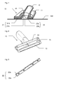
- the figure 1 represents a sectional view of a nozzle 10 according to the invention, on a floor to be cleaned 100.
- the nozzle 10 comprises a body 11 of the nozzle 10 made for example by plastic injection molding.
- the body 11 of the nozzle 10 comprises a sleeve 12 to be connected to a suction circuit of a vacuum cleaner, and the sleeve 12 communicates with a suction slot 15 formed in a sole of the nozzle 10.
- the sole of the nozzle 10 presents a suction and scraping surface which in the present case is essentially formed by first portions 21a and 22a of two tear-offs 21 and 22 respectively, and it is this suction and scraping surface which is preferably in contact with with the floor to be cleaned 100.
- the suction and scraping surface is formed essentially by the first portions 21a and 22a of the tear-offs 21 and 22 respectively and has a planar shape, but in a general manner, the surface suction is not necessarily flat and is not exclusively formed by the pull-son 21 and 22.
- the pull-yokes 21 and 22 also each have a second portion 21b and 22b respectively which extends into the suction slot 15.
- the tear-offs 21 and 22 start from an outer face or leading face and extend into the suction slot 15.
- the figure 2 represents the body 11 of the nozzle 10 of the figure 1 .
- the pull-threads 21 and 22 are patches. Indeed, the complex shapes of the pull-son with the first portions 21a or 22a, which are oriented by a non-negligible angle (an angle of between 30 ° and 150 ° for example) relative to the second portions 21b or 22b respectively , make it advantageous to make subsets.
- the assemblies can be made by gluing for example, and because of the aforementioned angle and delamination constraints, it may be advantageous to choose specific materials. In this case, it is advantageous to limit the use of these specific materials to the bonding areas and an insert in this material avoids making the nozzle 10 complete with this material.
- the insert can be polypropylene (PP) or acrylonitrile butadiene styrene (ABS).
- the pull-out can be overmolded. In this case, it eliminates the constraints of bonding, and it is also interesting to overmould the son-puller 21, 22 on the insert, to limit the size of overmolding mold.
- the figure 2 therefore represents the nozzle 10 without the pull-son 21 and 22, and on each side of the suction slot 15 are locations 13 and 14 to which will be fixed by gluing or clipping the son puller 21 and 22 respectively and their inserts.
- the figure 3 represents the pull-son 22, and the first portion 22a forms with the second portion 22b an angle less than 90 degrees. In this case, it is interesting to overmould the pull-thread 22 on its insert to avoid takeoffs because of the acute angle.
Landscapes
- Engineering & Computer Science (AREA)
- Mechanical Engineering (AREA)
- Nozzles For Electric Vacuum Cleaners (AREA)
Abstract
Description
- La présente invention concerne de manière générale un suceur d'aspirateur destiné à être monté sur un aspirateur.
- Il est connu dans l'art antérieur des suceurs d'aspirateur, et en particulier des suceurs d'aspirateur équipés de bandes de tissu agrippant dites arrache-fils, positionnées sur une surface d'aspiration et de grattage, comme présenté dans le document
EP 1 210 898 B1 . Ce système présente notamment l'inconvénient d'avoir une efficacité limitée, car des fils piégés par l'arrache-fils peuvent rester sur ce dernier et le saturer. Les fils peuvent simplement rester piégés sur l'arrache-fils sans être aspirés. De plus, on peut noter que les contraintes de fabrication doivent tenir compte du positionnement de l'arrache-fils dans une empreinte femelle de la semelle, ce qui impose des ajustements coûteux. - Un but de la présente invention est de répondre aux inconvénients du document de l'art antérieur mentionné ci-dessus et en particulier de proposer un suceur d'aspirateur avec un arrache-fils, qui présente une bonne efficacité de nettoyage.
- Pour cela un premier aspect de l'invention concerne un suceur d'aspirateur comprenant :
- une surface d'aspiration et de grattage,
- une fente d'aspiration, agencée pour être connectée à un circuit d'aspiration de l'aspirateur et débouchant sur la surface d'aspiration et de grattage,
- au moins un arrache-fils agencé sur la surface d'aspiration et de grattage, à côté de la fente d'aspiration,
- Selon un mode de réalisation, l'arrache-fils présente une première portion agencée sur la surface d'aspiration et de grattage, et une deuxième portion qui s'étend, en continuité avec la première portion, dans la fente d'aspiration. La deuxième portion qui s'étend dans la fente d'aspiration améliore encore le guidage vers le circuit d'aspiration des fils piégés par l'arrache-fils.
- Selon un mode de réalisation, le suceur comprend deux arrache-fils, chacun agencés de part et d'autre de la fente d'aspiration selon une direction de nettoyage.
- Selon un mode de réalisation, la deuxième portion s'étend le long d'une paroi de la fente d'aspiration. L'intégration est optimale avec la deuxième portion qui forme une partie de la paroi de la fente d'aspiration, et affleure celle-ci.
- Selon un mode de réalisation, le suceur comprend un corps de suceur, et l'arrache-fils est supporté par une pièce rapportée par rapport au corps de suceur. La fabrication est facilitée avec une pièce rapportée qui permet de choisir une matière adaptée pour fixer l'arrache-fils, sans devoir adopter cette matière pour tout le corps du suceur.
- Selon un mode de réalisation, l'arrache-fils est surmoulé sur la pièce rapportée.
- Selon un mode de réalisation, la première portion et la deuxième portion appartiennent chacune à des plans inclinés d'un angle inférieur ou égal à 90 degrés. Cette mise en oeuvre offre une alternative intéressante à du collage, en s'affranchissant des contraintes de délaminage d'un joint de colle qui sont présentes avec une telle géométrie complexe.
- Selon un mode de réalisation, l'arrache-fils est collé sur la pièce rapportée.
- Selon un mode de réalisation, la pièce rapportée est collée sur le corps de suceur.
- Selon un mode de réalisation, l'arrache-fils s'étend jusqu'à une face avant ou arrière du suceur. Le guidage des fils piégés est optimal, et la fabrication est simplifiée, car la semelle ne présente pas d'empreinte dans laquelle positionner l'arrache-fils, car celui-ci est débouchant sur la face extérieure et dans la fente d'aspiration.
- Un second aspect de l'invention est un aspirateur comprenant au moins un suceur d'aspirateur selon le premier aspect de l'invention.
- Un autre aspect de l'invention concerne un suceur d'aspirateur comprenant :
- une semelle avec une surface d'aspiration et de grattage,
- une fente d'aspiration, agencée pour être connectée à un circuit d'aspiration de l'aspirateur et débouchant sur la surface d'aspiration et de grattage,
- au moins un arrache-fils agencé sur la surface d'aspiration et de grattage, à côté de la fente d'aspiration,
- D'autres caractéristiques et avantages de la présente invention apparaîtront plus clairement à la lecture de la description détaillée qui suit d'un mode de réalisation de l'invention donné à titre d'exemple nullement limitatif et illustré par les dessins annexés, dans lesquels :
- la
figure 1 représente une vue isométrique d'un suceur d'aspirateur en coupe ; - la
figure 2 représente une vue isométrique du corps du suceur de lafigure 1 ; - la
figure 3 représente une vue isométrique d'un arrache-fils du suceur de lafigure 1 . - Dans la présente demande, les termes "suceur d'aspirateur" peuvent désigner plusieurs types de suceurs, mais l'invention concerne en particulier ceux qui sont destinés à pourvoir nettoyer des moquettes, des tissus, des coussins, des tapis ou des textiles, et retenir les corps étrangers allongés tels que fibres, fils, poils qui y seraient présents. Cela peut comprendre, de manière non limitative, un suceur large avec une brosse escamotable pour s'adapter à des sols durs ou des moquettes, un suceur étroit ou plat pour nettoyer exclusivement des coussins, des rideaux, des moquettes ou toute autre surface textile ou fibreuse.
- La
figure 1 représente un vue en coupe d'un suceur 10 selon l'invention, sur un sol à nettoyer 100. - Le suceur 10 comprend un corps 11 du suceur 10 réalisé par exemple par moulage par injection en matière plastique. Le corps 11 du suceur 10 comprend un manchon 12 pour être raccordé à un circuit d'aspiration d'un aspirateur, et le manchon 12 communique avec une fente d'aspiration 15 ménagée dans une semelle du suceur 10. La semelle du suceur 10 présente une surface d'aspiration et de grattage qui dans le cas présent est essentiellement formée par des premières portions 21a et 22a de deux arrache-fils 21 et 22 respectivement, et c'est cette surface d'aspiration et de grattage qui est préférentiellement en contact avec le sol à nettoyer 100.
- Il est à noter que dans le cas présent la surface d'aspiration et de grattage est formée essentiellement par les premières portions 21a et 22a des arrache-fils 21 et 22 respectivement et présente une forme plane, mais d'une manière générale, la surface d'aspiration n'est pas forcément plane et n'est pas exclusivement formée par les arrache-fils 21 et 22.
- Les arrache-fils 21 et 22 ont également chacun une deuxième portion 21 b et 22b respectivement qui s'étend dans la fente d'aspiration 15. En d'autres termes, les arrache-fils 21 et 22 partent d'une face extérieure ou face d'attaque et s'étendent jusque dans la fente d'aspiration 15. En conséquence, il n'y a aucune discontinuité de l'arrache-fils 21 ou 22 depuis la face d'attaque jusqu'à la fente d'aspiration, et les fils, fibres ou poils piégés par les arrache-fils 21 ou 22 lors du nettoyage seront donc guidés sans obstacle jusqu'à la fente d'aspiration 15 où ils seront aspirés.
- La
figure 2 représente le corps 11 du suceur 10 de lafigure 1 . Afin de faciliter la fabrication, les arrache-fils 21 et 22 (non visibles sur cettefigure 2 ) sont des pièces rapportées. En effet, les formes complexes des arrache-fils avec les premières portions 21a ou 22a, qui sont orientées d'un angle non négligeable (un angle compris entre 30° et 150° par exemple) par rapport aux deuxièmes portions 21 b ou 22b respectivement, font qu'il est avantageux de réaliser des sous-ensembles. - En effet, les assemblages peuvent être réalisés par collage par exemple, et en raison de l'angle susmentionné et des contraintes de délaminage, il peut être avantageux de choisir des matières spécifiques. Dans ce cas, il est intéressant de limiter l'usage de ces matières spécifiques aux zones de collage et une pièce rapportée dans cette matière permet d'éviter de réaliser le suceur 10 complet avec cette matière. On peut utiliser pour la pièce rapportée du polypropylène (PP) ou de l'acrylonitrile butadiène styrène (ABS).
- En alternative, l'arrache-fils peut être surmoulé. Dans ce cas, on s'affranchit des contraintes du collage, et il est également intéressant de surmouler l'arrache-fils 21, 22 sur la pièce rapportée, pour limiter la taille du moule de surmoulage.
- La
figure 2 représente donc le suceur 10 sans les arrache-fils 21 et 22, et de chaque côté de la fente d'aspiration 15 se trouvent des emplacements 13 et 14 sur lesquels seront fixés par collage ou clipsage les arrache-fils 21 et 22 respectivement et leurs pièces rapportées. - La
figure 3 représente l'arrache-fils 22, et la première portion 22a forme avec la deuxième portion 22b un angle inférieur à 90 degrés. Dans ce cas, il est intéressant de surmouler l'arrache-fils 22 sur sa pièce rapportée pour éviter les décollages en raison de l'angle aigu. - On comprendra que diverses modifications et/ou améliorations évidentes pour l'homme du métier peuvent être apportées aux différents modes de réalisation de l'invention décrits dans la présente description sans sortir du cadre de l'invention défini par les revendications annexées.
Claims (10)
- Suceur (10) d'aspirateur comprenant :- une surface d'aspiration et de grattage,- une fente d'aspiration (15), agencée pour être connectée à un circuit d'aspiration de l'aspirateur et débouchant sur la surface d'aspiration et de grattage,- au moins un arrache-fils (21, 22) agencé sur la surface d'aspiration et de grattage, à côté de la fente d'aspiration (15),caractérisé en ce que l'arrache-fils (21, 22) comprend une partie qui débouche dans la fente d'aspiration (15).
- Suceur (10) d'aspirateur selon la revendication précédente, caractérisé en ce que l'arrache-fils (21, 22) présente une première portion (21 a, 22a) agencée sur la surface d'aspiration et de grattage, et une deuxième portion (21 b, 22b) qui s'étend, en continuité avec la première portion (21 a, 22a), dans la fente d'aspiration (15).
- Suceur (10) d'aspirateur selon la revendication précédente, caractérisé en ce que la deuxième portion (21 b, 22b) s'étend le long d'une paroi de la fente d'aspiration (15).
- Suceur (10) d'aspirateur selon les revendications 2 ou 3, caractérisé en ce que la première portion (21 a, 22a) et la deuxième portion (21 b, 22b) appartiennent chacune à des plans inclinés d'un angle inférieur ou égal à 90 degrés.
- Suceur (10) d'aspirateur selon l'une des revendications précédentes, comprenant un corps (11) de suceur (10), et caractérisé en ce que l'arrache-fils (21, 22) est supporté par une pièce rapportée par rapport au corps (11) de suceur (10).
- Suceur (10) d'aspirateur selon la revendication précédente, caractérisé en ce que l'arrache-fils (21, 22) est surmoulé sur la pièce rapportée.
- Suceur (10) d'aspirateur selon la revendication 5, caractérisé en ce que l'arrache-fils (21, 22) est collé sur la pièce rapportée.
- Suceur (10) d'aspirateur selon l'une des revendications 5 à 7, caractérisé en ce que la pièce rapportée est collée sur le corps (11) de suceur (10).
- Suceur (10) d'aspirateur selon l'une des revendications précédentes, caractérisé en ce que l'arrache-fils (21, 22) s'étend jusqu'à une face avant ou arrière du suceur (10).
- Aspirateur comprenant au moins un suceur (10) d'aspirateur selon l'une des revendications précédentes.
Applications Claiming Priority (1)
| Application Number | Priority Date | Filing Date | Title |
|---|---|---|---|
| FR1358537A FR3009943B1 (fr) | 2013-09-05 | 2013-09-05 | Suceur d'aspirateur |
Publications (2)
| Publication Number | Publication Date |
|---|---|
| EP2848175A1 true EP2848175A1 (fr) | 2015-03-18 |
| EP2848175B1 EP2848175B1 (fr) | 2020-05-20 |
Family
ID=49382503
Family Applications (1)
| Application Number | Title | Priority Date | Filing Date |
|---|---|---|---|
| EP14183096.8A Active EP2848175B1 (fr) | 2013-09-05 | 2014-09-01 | Suceur d'aspirateur |
Country Status (3)
| Country | Link |
|---|---|
| EP (1) | EP2848175B1 (fr) |
| ES (1) | ES2797544T3 (fr) |
| FR (1) | FR3009943B1 (fr) |
Citations (5)
| Publication number | Priority date | Publication date | Assignee | Title |
|---|---|---|---|---|
| DE2100465A1 (de) * | 1971-01-07 | 1972-07-20 | Schwab Geb Gitschel H | Fadenaufnehmer für eine Vorrichtung zum Säubern von Textilien |
| EP0118765A1 (fr) * | 1983-02-08 | 1984-09-19 | Zaklady Zmechanizowanego Sprzetu Domowego "Predom-Zelmer" | Accroche-fils d'un suceur ou d'une brosse d'aspiration |
| EP1210898B1 (fr) | 2000-11-22 | 2004-03-24 | Wessel-Werk Gmbh | Suceur pour aspirateur destiné au nettoyage des sols, en particulier aspirateur domestique |
| WO2008111891A1 (fr) * | 2007-03-09 | 2008-09-18 | Aktiebolaget Electrolux | Suceur d'aspirateur |
| EP2229858A1 (fr) * | 2009-03-20 | 2010-09-22 | Bissell Homecare, Inc. | Saugzubehörwerkzeug |
-
2013
- 2013-09-05 FR FR1358537A patent/FR3009943B1/fr not_active Expired - Fee Related
-
2014
- 2014-09-01 EP EP14183096.8A patent/EP2848175B1/fr active Active
- 2014-09-01 ES ES14183096T patent/ES2797544T3/es active Active
Patent Citations (5)
| Publication number | Priority date | Publication date | Assignee | Title |
|---|---|---|---|---|
| DE2100465A1 (de) * | 1971-01-07 | 1972-07-20 | Schwab Geb Gitschel H | Fadenaufnehmer für eine Vorrichtung zum Säubern von Textilien |
| EP0118765A1 (fr) * | 1983-02-08 | 1984-09-19 | Zaklady Zmechanizowanego Sprzetu Domowego "Predom-Zelmer" | Accroche-fils d'un suceur ou d'une brosse d'aspiration |
| EP1210898B1 (fr) | 2000-11-22 | 2004-03-24 | Wessel-Werk Gmbh | Suceur pour aspirateur destiné au nettoyage des sols, en particulier aspirateur domestique |
| WO2008111891A1 (fr) * | 2007-03-09 | 2008-09-18 | Aktiebolaget Electrolux | Suceur d'aspirateur |
| EP2229858A1 (fr) * | 2009-03-20 | 2010-09-22 | Bissell Homecare, Inc. | Saugzubehörwerkzeug |
Also Published As
| Publication number | Publication date |
|---|---|
| FR3009943A1 (fr) | 2015-03-06 |
| ES2797544T3 (es) | 2020-12-02 |
| FR3009943B1 (fr) | 2015-09-04 |
| EP2848175B1 (fr) | 2020-05-20 |
Similar Documents
| Publication | Publication Date | Title |
|---|---|---|
| EP2879921B1 (fr) | Dispositif de connexion entre un bras d'essuyage et un balai d'essuyage, comprenant un tube surmoule | |
| EP3041652B1 (fr) | Dispositif de retenue a crochets | |
| USD875333S1 (en) | Wet/dry vacuum cleaner with handle | |
| CA2849235A1 (fr) | Suceur d'aspirateur | |
| USD1001405S1 (en) | Windshield cleaner | |
| CN107072387B (zh) | 具有光透射手柄的牙刷 | |
| EP2848175B1 (fr) | Suceur d'aspirateur | |
| FR3059962A1 (fr) | Dispositif de connexion pour la liaison d'un balai d'essuyage a un bras d'entrainement pour vehicule | |
| EP1634800A1 (fr) | Ensemble de bloc-avant pour un véhicule automobile | |
| EP3539434B1 (fr) | Suceur d'aspirateur pourvu d'une surface de glissement présentant un bord arrière arrondi | |
| EP3556273B1 (fr) | Suceur d'aspirateur équipé d'un canal d'aspiration principal et d'un canal d'aspiration secondaire | |
| FR2994145A1 (fr) | Dispositif de connexion entre un bras d'essuyage et un balai d'essuyage | |
| FR3045422B1 (fr) | Dispositif de lissage d'un cordon d’etancheite | |
| LU88755A1 (fr) | Ustensile pour serpillières pour le balayage à voie humide ou à sec avec une semelle tendre sous-jacente munie d'ailettes souples réalisée par thermoformage sur la planchette portante en matière plastique se trouvant au-dessus | |
| EP1488728B1 (fr) | Suceur d'aspirateur | |
| FR2486993A1 (fr) | Pince de fixation de baguette | |
| EP1520504B1 (fr) | Suceur d'aspirateur | |
| FR2936440A1 (fr) | Element d'habillage interieur muni d'un article ajoute pour vehicule automobile et son procede de fabrication | |
| FR2929580A1 (fr) | Pied avant renforce d'un vehicule automobile. | |
| EP2537712A1 (fr) | Ensemble d'habillage d'une partie de l'habitacle d'un véhicule automobile comprenant une pluralité de pièces d'habillage | |
| FR3033998A1 (fr) | ||
| EP0056534A1 (fr) | Pare-chocs pour chariot destiné à recevoir des marchandises diverses, notamment dans les magasins à grande surface | |
| FR3142075A1 (fr) | Suceur d’aspirateur pourvu d’une butée anti-basculement déformable | |
| FR2972398A1 (fr) | Appui-tete de siege recyclable | |
| EP1369074A1 (fr) | Suceur d'aspirateur à dispositif de raclage |
Legal Events
| Date | Code | Title | Description |
|---|---|---|---|
| PUAI | Public reference made under article 153(3) epc to a published international application that has entered the european phase |
Free format text: ORIGINAL CODE: 0009012 |
|
| 17P | Request for examination filed |
Effective date: 20140901 |
|
| AK | Designated contracting states |
Kind code of ref document: A1 Designated state(s): AL AT BE BG CH CY CZ DE DK EE ES FI FR GB GR HR HU IE IS IT LI LT LU LV MC MK MT NL NO PL PT RO RS SE SI SK SM TR |
|
| AX | Request for extension of the european patent |
Extension state: BA ME |
|
| R17P | Request for examination filed (corrected) |
Effective date: 20150918 |
|
| RBV | Designated contracting states (corrected) |
Designated state(s): AL AT BE BG CH CY CZ DE DK EE ES FI FR GB GR HR HU IE IS IT LI LT LU LV MC MK MT NL NO PL PT RO RS SE SI SK SM TR |
|
| RAP1 | Party data changed (applicant data changed or rights of an application transferred) |
Owner name: SEB S.A. |
|
| GRAP | Despatch of communication of intention to grant a patent |
Free format text: ORIGINAL CODE: EPIDOSNIGR1 |
|
| STAA | Information on the status of an ep patent application or granted ep patent |
Free format text: STATUS: GRANT OF PATENT IS INTENDED |
|
| INTG | Intention to grant announced |
Effective date: 20191219 |
|
| GRAS | Grant fee paid |
Free format text: ORIGINAL CODE: EPIDOSNIGR3 |
|
| GRAA | (expected) grant |
Free format text: ORIGINAL CODE: 0009210 |
|
| STAA | Information on the status of an ep patent application or granted ep patent |
Free format text: STATUS: THE PATENT HAS BEEN GRANTED |
|
| AK | Designated contracting states |
Kind code of ref document: B1 Designated state(s): AL AT BE BG CH CY CZ DE DK EE ES FI FR GB GR HR HU IE IS IT LI LT LU LV MC MK MT NL NO PL PT RO RS SE SI SK SM TR |
|
| REG | Reference to a national code |
Ref country code: GB Ref legal event code: FG4D Free format text: NOT ENGLISH |
|
| REG | Reference to a national code |
Ref country code: CH Ref legal event code: EP |
|
| REG | Reference to a national code |
Ref country code: DE Ref legal event code: R096 Ref document number: 602014065652 Country of ref document: DE |
|
| REG | Reference to a national code |
Ref country code: AT Ref legal event code: REF Ref document number: 1272045 Country of ref document: AT Kind code of ref document: T Effective date: 20200615 |
|
| REG | Reference to a national code |
Ref country code: LT Ref legal event code: MG4D |
|
| REG | Reference to a national code |
Ref country code: NL Ref legal event code: MP Effective date: 20200520 |
|
| PG25 | Lapsed in a contracting state [announced via postgrant information from national office to epo] |
Ref country code: GR Free format text: LAPSE BECAUSE OF FAILURE TO SUBMIT A TRANSLATION OF THE DESCRIPTION OR TO PAY THE FEE WITHIN THE PRESCRIBED TIME-LIMIT Effective date: 20200821 Ref country code: NO Free format text: LAPSE BECAUSE OF FAILURE TO SUBMIT A TRANSLATION OF THE DESCRIPTION OR TO PAY THE FEE WITHIN THE PRESCRIBED TIME-LIMIT Effective date: 20200820 Ref country code: FI Free format text: LAPSE BECAUSE OF FAILURE TO SUBMIT A TRANSLATION OF THE DESCRIPTION OR TO PAY THE FEE WITHIN THE PRESCRIBED TIME-LIMIT Effective date: 20200520 Ref country code: PT Free format text: LAPSE BECAUSE OF FAILURE TO SUBMIT A TRANSLATION OF THE DESCRIPTION OR TO PAY THE FEE WITHIN THE PRESCRIBED TIME-LIMIT Effective date: 20200921 Ref country code: IS Free format text: LAPSE BECAUSE OF FAILURE TO SUBMIT A TRANSLATION OF THE DESCRIPTION OR TO PAY THE FEE WITHIN THE PRESCRIBED TIME-LIMIT Effective date: 20200920 Ref country code: LT Free format text: LAPSE BECAUSE OF FAILURE TO SUBMIT A TRANSLATION OF THE DESCRIPTION OR TO PAY THE FEE WITHIN THE PRESCRIBED TIME-LIMIT Effective date: 20200520 Ref country code: SE Free format text: LAPSE BECAUSE OF FAILURE TO SUBMIT A TRANSLATION OF THE DESCRIPTION OR TO PAY THE FEE WITHIN THE PRESCRIBED TIME-LIMIT Effective date: 20200520 |
|
| PG25 | Lapsed in a contracting state [announced via postgrant information from national office to epo] |
Ref country code: LV Free format text: LAPSE BECAUSE OF FAILURE TO SUBMIT A TRANSLATION OF THE DESCRIPTION OR TO PAY THE FEE WITHIN THE PRESCRIBED TIME-LIMIT Effective date: 20200520 Ref country code: HR Free format text: LAPSE BECAUSE OF FAILURE TO SUBMIT A TRANSLATION OF THE DESCRIPTION OR TO PAY THE FEE WITHIN THE PRESCRIBED TIME-LIMIT Effective date: 20200520 Ref country code: BG Free format text: LAPSE BECAUSE OF FAILURE TO SUBMIT A TRANSLATION OF THE DESCRIPTION OR TO PAY THE FEE WITHIN THE PRESCRIBED TIME-LIMIT Effective date: 20200820 Ref country code: RS Free format text: LAPSE BECAUSE OF FAILURE TO SUBMIT A TRANSLATION OF THE DESCRIPTION OR TO PAY THE FEE WITHIN THE PRESCRIBED TIME-LIMIT Effective date: 20200520 |
|
| REG | Reference to a national code |
Ref country code: ES Ref legal event code: FG2A Ref document number: 2797544 Country of ref document: ES Kind code of ref document: T3 Effective date: 20201202 |
|
| REG | Reference to a national code |
Ref country code: AT Ref legal event code: MK05 Ref document number: 1272045 Country of ref document: AT Kind code of ref document: T Effective date: 20200520 |
|
| PG25 | Lapsed in a contracting state [announced via postgrant information from national office to epo] |
Ref country code: AL Free format text: LAPSE BECAUSE OF FAILURE TO SUBMIT A TRANSLATION OF THE DESCRIPTION OR TO PAY THE FEE WITHIN THE PRESCRIBED TIME-LIMIT Effective date: 20200520 Ref country code: NL Free format text: LAPSE BECAUSE OF FAILURE TO SUBMIT A TRANSLATION OF THE DESCRIPTION OR TO PAY THE FEE WITHIN THE PRESCRIBED TIME-LIMIT Effective date: 20200520 |
|
| PG25 | Lapsed in a contracting state [announced via postgrant information from national office to epo] |
Ref country code: EE Free format text: LAPSE BECAUSE OF FAILURE TO SUBMIT A TRANSLATION OF THE DESCRIPTION OR TO PAY THE FEE WITHIN THE PRESCRIBED TIME-LIMIT Effective date: 20200520 Ref country code: DK Free format text: LAPSE BECAUSE OF FAILURE TO SUBMIT A TRANSLATION OF THE DESCRIPTION OR TO PAY THE FEE WITHIN THE PRESCRIBED TIME-LIMIT Effective date: 20200520 Ref country code: AT Free format text: LAPSE BECAUSE OF FAILURE TO SUBMIT A TRANSLATION OF THE DESCRIPTION OR TO PAY THE FEE WITHIN THE PRESCRIBED TIME-LIMIT Effective date: 20200520 Ref country code: RO Free format text: LAPSE BECAUSE OF FAILURE TO SUBMIT A TRANSLATION OF THE DESCRIPTION OR TO PAY THE FEE WITHIN THE PRESCRIBED TIME-LIMIT Effective date: 20200520 Ref country code: SM Free format text: LAPSE BECAUSE OF FAILURE TO SUBMIT A TRANSLATION OF THE DESCRIPTION OR TO PAY THE FEE WITHIN THE PRESCRIBED TIME-LIMIT Effective date: 20200520 Ref country code: CZ Free format text: LAPSE BECAUSE OF FAILURE TO SUBMIT A TRANSLATION OF THE DESCRIPTION OR TO PAY THE FEE WITHIN THE PRESCRIBED TIME-LIMIT Effective date: 20200520 |
|
| REG | Reference to a national code |
Ref country code: DE Ref legal event code: R097 Ref document number: 602014065652 Country of ref document: DE |
|
| PG25 | Lapsed in a contracting state [announced via postgrant information from national office to epo] |
Ref country code: PL Free format text: LAPSE BECAUSE OF FAILURE TO SUBMIT A TRANSLATION OF THE DESCRIPTION OR TO PAY THE FEE WITHIN THE PRESCRIBED TIME-LIMIT Effective date: 20200520 Ref country code: SK Free format text: LAPSE BECAUSE OF FAILURE TO SUBMIT A TRANSLATION OF THE DESCRIPTION OR TO PAY THE FEE WITHIN THE PRESCRIBED TIME-LIMIT Effective date: 20200520 |
|
| PLBE | No opposition filed within time limit |
Free format text: ORIGINAL CODE: 0009261 |
|
| STAA | Information on the status of an ep patent application or granted ep patent |
Free format text: STATUS: NO OPPOSITION FILED WITHIN TIME LIMIT |
|
| 26N | No opposition filed |
Effective date: 20210223 |
|
| PG25 | Lapsed in a contracting state [announced via postgrant information from national office to epo] |
Ref country code: MC Free format text: LAPSE BECAUSE OF FAILURE TO SUBMIT A TRANSLATION OF THE DESCRIPTION OR TO PAY THE FEE WITHIN THE PRESCRIBED TIME-LIMIT Effective date: 20200520 |
|
| REG | Reference to a national code |
Ref country code: CH Ref legal event code: PL |
|
| PG25 | Lapsed in a contracting state [announced via postgrant information from national office to epo] |
Ref country code: SI Free format text: LAPSE BECAUSE OF FAILURE TO SUBMIT A TRANSLATION OF THE DESCRIPTION OR TO PAY THE FEE WITHIN THE PRESCRIBED TIME-LIMIT Effective date: 20200520 |
|
| REG | Reference to a national code |
Ref country code: BE Ref legal event code: MM Effective date: 20200930 |
|
| PG25 | Lapsed in a contracting state [announced via postgrant information from national office to epo] |
Ref country code: LU Free format text: LAPSE BECAUSE OF NON-PAYMENT OF DUE FEES Effective date: 20200901 |
|
| PG25 | Lapsed in a contracting state [announced via postgrant information from national office to epo] |
Ref country code: CH Free format text: LAPSE BECAUSE OF NON-PAYMENT OF DUE FEES Effective date: 20200930 Ref country code: BE Free format text: LAPSE BECAUSE OF NON-PAYMENT OF DUE FEES Effective date: 20200930 Ref country code: IE Free format text: LAPSE BECAUSE OF NON-PAYMENT OF DUE FEES Effective date: 20200901 Ref country code: LI Free format text: LAPSE BECAUSE OF NON-PAYMENT OF DUE FEES Effective date: 20200930 |
|
| PGFP | Annual fee paid to national office [announced via postgrant information from national office to epo] |
Ref country code: IT Payment date: 20210913 Year of fee payment: 8 |
|
| PGFP | Annual fee paid to national office [announced via postgrant information from national office to epo] |
Ref country code: ES Payment date: 20211005 Year of fee payment: 8 |
|
| PG25 | Lapsed in a contracting state [announced via postgrant information from national office to epo] |
Ref country code: TR Free format text: LAPSE BECAUSE OF FAILURE TO SUBMIT A TRANSLATION OF THE DESCRIPTION OR TO PAY THE FEE WITHIN THE PRESCRIBED TIME-LIMIT Effective date: 20200520 Ref country code: MT Free format text: LAPSE BECAUSE OF FAILURE TO SUBMIT A TRANSLATION OF THE DESCRIPTION OR TO PAY THE FEE WITHIN THE PRESCRIBED TIME-LIMIT Effective date: 20200520 Ref country code: CY Free format text: LAPSE BECAUSE OF FAILURE TO SUBMIT A TRANSLATION OF THE DESCRIPTION OR TO PAY THE FEE WITHIN THE PRESCRIBED TIME-LIMIT Effective date: 20200520 |
|
| PG25 | Lapsed in a contracting state [announced via postgrant information from national office to epo] |
Ref country code: MK Free format text: LAPSE BECAUSE OF FAILURE TO SUBMIT A TRANSLATION OF THE DESCRIPTION OR TO PAY THE FEE WITHIN THE PRESCRIBED TIME-LIMIT Effective date: 20200520 |
|
| PGFP | Annual fee paid to national office [announced via postgrant information from national office to epo] |
Ref country code: GB Payment date: 20220923 Year of fee payment: 9 |
|
| REG | Reference to a national code |
Ref country code: ES Ref legal event code: FD2A Effective date: 20231026 |
|
| PG25 | Lapsed in a contracting state [announced via postgrant information from national office to epo] |
Ref country code: IT Free format text: LAPSE BECAUSE OF NON-PAYMENT OF DUE FEES Effective date: 20220901 |
|
| PG25 | Lapsed in a contracting state [announced via postgrant information from national office to epo] |
Ref country code: ES Free format text: LAPSE BECAUSE OF NON-PAYMENT OF DUE FEES Effective date: 20220902 |
|
| PG25 | Lapsed in a contracting state [announced via postgrant information from national office to epo] |
Ref country code: ES Free format text: LAPSE BECAUSE OF NON-PAYMENT OF DUE FEES Effective date: 20220902 |
|
| GBPC | Gb: european patent ceased through non-payment of renewal fee |
Effective date: 20230901 |
|
| PG25 | Lapsed in a contracting state [announced via postgrant information from national office to epo] |
Ref country code: GB Free format text: LAPSE BECAUSE OF NON-PAYMENT OF DUE FEES Effective date: 20230901 |
|
| PG25 | Lapsed in a contracting state [announced via postgrant information from national office to epo] |
Ref country code: GB Free format text: LAPSE BECAUSE OF NON-PAYMENT OF DUE FEES Effective date: 20230901 |
|
| PGFP | Annual fee paid to national office [announced via postgrant information from national office to epo] |
Ref country code: DE Payment date: 20250916 Year of fee payment: 12 |
|
| PGFP | Annual fee paid to national office [announced via postgrant information from national office to epo] |
Ref country code: FR Payment date: 20250929 Year of fee payment: 12 |