EP2848210A1 - Tubérosité au-dessous du tibia d'ostéotomie par forage multiples - Google Patents
Tubérosité au-dessous du tibia d'ostéotomie par forage multiples Download PDFInfo
- Publication number
- EP2848210A1 EP2848210A1 EP13185055.4A EP13185055A EP2848210A1 EP 2848210 A1 EP2848210 A1 EP 2848210A1 EP 13185055 A EP13185055 A EP 13185055A EP 2848210 A1 EP2848210 A1 EP 2848210A1
- Authority
- EP
- European Patent Office
- Prior art keywords
- guide device
- passageways
- osteotomy
- examples
- tibia
- Prior art date
- Legal status (The legal status is an assumption and is not a legal conclusion. Google has not performed a legal analysis and makes no representation as to the accuracy of the status listed.)
- Granted
Links
Images





Classifications
-
- A—HUMAN NECESSITIES
- A61—MEDICAL OR VETERINARY SCIENCE; HYGIENE
- A61B—DIAGNOSIS; SURGERY; IDENTIFICATION
- A61B17/00—Surgical instruments, devices or methods
- A61B17/16—Instruments for performing osteoclasis; Drills or chisels for bones; Trepans
- A61B17/17—Guides or aligning means for drills, mills, pins or wires
- A61B17/1739—Guides or aligning means for drills, mills, pins or wires specially adapted for particular parts of the body
- A61B17/1764—Guides or aligning means for drills, mills, pins or wires specially adapted for particular parts of the body for the knee
-
- A—HUMAN NECESSITIES
- A61—MEDICAL OR VETERINARY SCIENCE; HYGIENE
- A61B—DIAGNOSIS; SURGERY; IDENTIFICATION
- A61B17/00—Surgical instruments, devices or methods
- A61B17/14—Surgical saws
- A61B17/15—Guides therefor
- A61B17/151—Guides therefor for corrective osteotomy
-
- A—HUMAN NECESSITIES
- A61—MEDICAL OR VETERINARY SCIENCE; HYGIENE
- A61B—DIAGNOSIS; SURGERY; IDENTIFICATION
- A61B17/00—Surgical instruments, devices or methods
- A61B17/14—Surgical saws
- A61B17/15—Guides therefor
- A61B17/151—Guides therefor for corrective osteotomy
- A61B17/152—Guides therefor for corrective osteotomy for removing a wedge-shaped piece of bone
-
- A—HUMAN NECESSITIES
- A61—MEDICAL OR VETERINARY SCIENCE; HYGIENE
- A61B—DIAGNOSIS; SURGERY; IDENTIFICATION
- A61B17/00—Surgical instruments, devices or methods
- A61B17/14—Surgical saws
- A61B17/15—Guides therefor
- A61B17/154—Guides therefor for preparing bone for knee prosthesis
- A61B17/157—Cutting tibia
-
- A—HUMAN NECESSITIES
- A61—MEDICAL OR VETERINARY SCIENCE; HYGIENE
- A61B—DIAGNOSIS; SURGERY; IDENTIFICATION
- A61B17/00—Surgical instruments, devices or methods
- A61B17/56—Surgical instruments or methods for treatment of bones or joints; Devices specially adapted therefor
- A61B17/58—Surgical instruments or methods for treatment of bones or joints; Devices specially adapted therefor for osteosynthesis, e.g. bone plates, screws or setting implements
- A61B17/68—Internal fixation devices, including fasteners and spinal fixators, even if a part thereof projects from the skin
- A61B17/80—Cortical plates, i.e. bone plates; Instruments for holding or positioning cortical plates, or for compressing bones attached to cortical plates
- A61B17/8095—Wedge osteotomy devices
-
- A—HUMAN NECESSITIES
- A61—MEDICAL OR VETERINARY SCIENCE; HYGIENE
- A61K—PREPARATIONS FOR MEDICAL, DENTAL OR TOILETRY PURPOSES
- A61K35/00—Medicinal preparations containing materials or reaction products thereof with undetermined constitution
- A61K35/12—Materials from mammals; Compositions comprising non-specified tissues or cells; Compositions comprising non-embryonic stem cells; Genetically modified cells
- A61K35/14—Blood; Artificial blood
Definitions
- the embodiments disclosed herein relate generally to surgical devices, kits and methods that involve the use thereof.
- the methods of using the surgical devices and kits can involve performing tibial and/or fibular osteotomies and/or administering stem cells.
- Varus or valgus deformity which is a malalignment or misalignment of the knee, can be caused by several factors including for example wear and tear of the cartilage, misalignment at birth, post-traumatic fracture, osteoarthritis or rheumatoid arthritis.
- Current available treatments are limited to tibial osteotomy (open or closed, with or without bone graft) or unicondylar knee replacementor a total knee replacement.
- the degree of deformities and the patient age are usually the two main factors that decide which is the better option. The former method has been performed on younger patients while the latter on patients over 50 years.
- knee replacements can lead to complications, for example, infection, blood clots and injury to nerves or vessels.
- knee replacements generally involve replacement of a natural part of the body with a synthetic component, which needs to be replaced via another surgery when the synthetic component reaches its lifespan.
- this procedure is generally not recommended for younger and/or active patients as the prosthesis cannot offer a high functional activity level and does not last throughout the lifetime of the patient.
- osteotomy is generally performed above the tibial tuberosity at the level of the cancellous bone, which can cause tibial plateau fracture or collapse.
- the surgical kit includes an osteotomy guide device and/or a bone spacer guide device.
- the surgical kit can be used in a surgical method for correcting a misalignment of a lower limb, e.g., a knee joint, that involves a fibular osteotomy, a tibial osteotomy, and/or administration of stem cells.
- the surgical method involves correction of a varus deformity.
- the disclosed method involves performing tibial osteotomy below the tibial tuberosity.
- affixation of a fixing plate is better when performing tibial osteotomy below the tibial tuberosity, as compared to when performing tibial osteotomy above the tibial tuberosity because there is less chance of the cancellous bone collapsing.
- tibial osteotomy below the tibial tuberosity involves cutting into the cortical bone
- tibial osteotomy above the tibial tuberosity involves cutting into the cancellous bone.
- tibial osteotomy below the tibial tuberosity is generally not recommended to relatively older patients, for example, older patients who are in the fourth decade or more of their lives.
- the present inventors have found that the disclosed method that involves, e.g., the use of the disclosed surgical kit in performing fibular osteotomy and/or tibial osteotomy, for example, performed below the tibial tuberosity, can lead to successful union of the bone following the procedure(s), even in relatively older patients, such as for example, patients who are past the fourth decade of their lives.
- a fibular osteotomy can be generally performed when a tibial osteotomy is performed below the tibial tuberosity.
- the disclosed methods also can lead to: (1) correction of misalignment; (2) regeneration of the bone in a relatively short time period as compared to that of conventional methods; (3) minimizing neurovascular bundle injury; (4) reducing stiffness in the knee after the procedure; (5) a smaller incision at the site of the respective osteotomies as compared to that of conventional methods; (6) ease in performing the surgery; and (7) minimum disruption of the periosteum as compared to that of conventional methods which involve sawing.
- the surgical kit is used for performing fibular and/or tibial osteotomy.
- the tibial osteotomy can involve drilling of the tibia at a tibial osteotomy site through the cortices of the bone.
- drilling of the tibia can involve the use of a drill and a cutting tool as generally known in the art.
- the cutting tool utilized can be a drill bit to create drill holes in the tibia.
- the fibular osteotomy can be performed at a fibular osteotomy site, for example, at a distal third position of the fibula as is generally known in the art.
- the fibular osteotomy can be conducted at approximately 45 ⁇ 15 degrees relative to a neutral axis 1-1.
- the surgical kit includes an osteotomy guide device.
- the osteotomy guide device is configured to allow drilling to occur around the tibia and across a horizontal cross-sectional plane of the tibia so that the direction of each of the drill holes that are formed in the tibia is substantially parallel to or on the same horizontal cross-sectional plane of the tibia.
- the osteotomy guide device allows drilling to be conducted efficiently and accurately.
- the osteotomy guide device has a base having a central portion, an upwardly extending portion and a downwardly extending portion.
- the central portion is an elongated portion that extends from a first end to a second end, thereby defining a vertical axis when the device is viewed in top view.
- the upwardly extending portion extends upwardly from the first end of the central portion while the downwardly extending portion extends downwardly from the second end of the central portion.
- the upwardly extending portion is a latching portion.
- the latching portion is in the shape of a hook and is dimensioned so that a tip of the hook can latch onto a tibia.
- the latching portion hooks toward an inner side of the base.
- the latching portion functions to fix the device onto the tibia so that the device is in a fixed state.
- the downwardly extending portion includes a flared portion that has a curvature.
- the flared portion curves toward the inner side of the base.
- the angle of the curvature can be about 0 to about 90 degrees relative to the vertical axis defined by the central portion. In some examples, the angle of the curvature can be 0 ⁇ 15 to 90 ⁇ 15 degrees relative to the vertical axis defined by the central portion. In some examples, the angle of the curvature can be 45 ⁇ 15 degrees.
- the angle of curvature of the flared portion can be about 0 to 45 degrees relative to the vertical axis defined by the central portion, more particularly 30 to 45 degrees, 35 to 45 degrees, or 40 to 45 degrees relative to the vertical axis defined by the central portion.
- the osteotomy guide comprises a central portion, an upwardly extending portion and a downwardly extending portion, wherein the central portion is an elongated portion that defines a vertical axis, the elongated portion having an inner side and an opposite outward side wherein in use, when the device positioned in the body, the inner side is located against the bone (tibia), and the outward side is accessible.
- the upwardly extending portion can form a curved hook wherein the inner side of the elongated portion forms the inside of the hook, and the downwardly extending portion includes a flared portion that has a curvature such that as the downwardly extending portion extends it curves such that the inner side of the elongated portion is the inner surface of the curve of the flared portion and the outward side of the elongated portion is the outside surface of the curve of the flared portion.
- the length of the osteotomy guide device along the vertical axis can be about 60 to 80 mm, more particularly 65 to 75 mm, more particularly about 68 to 70 mm.
- the tip of the curved hook of the upwardly extending portion and the tip of the flared portion of the downwardly extending portion are in a vertical axis spaced apart from the inner side of the central portion by about 16 to 18 mm.
- the central portion and the flared portion are generally continuous so that an outline of the central portion and the flared portion generally follows, at least in part, an outline of a cross-section of the tibia when the device is in the fixed state.
- the central portion and flared portion can be manufactured in a plurality of parts wherein the parts can be conjoined together to form the complete device.
- the plurality of parts when conjoined together can be provided with a locking mechanism to retain the parts in the form of the complete device.
- the base of the osteotomy guide device includes a plurality of passageways that are formed through a thickness of the base.
- some of the passageways are adapted for positioning a direction of the drilling.
- some of the passageways are adapted for inserting a handle or a stabilizing member, e.g., a wire.
- the base has a median axis, a first sagittal axis and a second sagittal axis as viewed in side view.
- the median axis is substantially parallel to a median plane of the base, where the median plane is a plane that divides the device into substantially two equal halves.
- the first and second sagittal axes are substantially parallel to the median axis.
- the device can be formed of stainless steel or titanium or titanium alloys.
- each of the passageways that are adapted for positioning the direction of the drill has an inlet and an outlet, and the inlets and/or outlets are provided along the median axis of the base.
- each of the passageways extends from the inlet to the outlet in a direction that is substantially parallel to or on a horizontal cross-sectional plane when the device is in the fixed state.
- two passageways are provided in the central portion in a first sagittal axis and two passageways in a second sagittal axis.
- the passageways can be spaced apart along a vertical axis by 6 mm (spacing from a central point of one of the passageways to the other, not from one edge of the passageway to another).
- passageways suitably 19 passageways are provided in the device.
- passageways are provided in the upwardly extending portion in a first sagittal axis, median axis and second sagittal axis.
- passageways are provided in the downwardly extending portion in a first sagittal axis, median axis and second sagittal axis.
- about 9 passageways can be provided in the upwardly extending portion and about 10 passageways can be provided in the downwardly extending portion.
- the passageways can be spaced apart by 4 mm.
- the passageways along the median axis are offset from those of the first and second sagittal axis.
- At least one of the passageways are adapted to receive a handle such that a user can hold the device by the handle rather than gripping the actual device when it is inserted into the surgical site.
- such a passageway may be adapted to allow a portion of the handle to screw into the passageway such that the device can be held by the handle.
- each of the passageways that are adapted for positioning a stabilizing member, e.g., a wire, and/or a handle has an inlet and an outlet.
- the inlets and/or outlets are formed along the first sagittal axis and/or the second sagittal axis.
- the surgical kit further includes a bone spacer guide device.
- the device has a main body having a central portion with two opposing side portions that extend outwardly from the central portion.
- the central portion has a downwardly extending wedge portion.
- the wedge portion may be detached from the main body.
- each of the side portions includes a groove adjacent the central portion, and an arm portion that extends from the groove.
- the grooves are adapted for positioning a stabilizing member, e.g., wires such as k-wires.
- each of the arm portions include passageways adapted for inserting a stabilizing member, e.g., a wire such as a k-wire, for example, in parallel to one another and/or perpendicular to the long-axis of the tibia so as to stabilize the device.
- a stabilizing member e.g., a wire such as a k-wire
- the disclosed method involves the use of the surgical kit.
- fibular osteotomy and/or tibial osteotomy is performed.
- the tibial osteotomy is performed below the tibial tuberosity.
- the tibial osteotomy is performed at a distal insertion of a patella tendon below the tibial tuberosity.
- the method involves fixing the osteotomy guide device on a tibia, stabilizing the osteotomy guide device, for example, a stabilizing member such as a wire, pin or screw, drilling across the bone through the passageways of the osteotomy guide device, removing the osteotomy guide device, cracking open the tibia along the drill holes that are formed in the tibia to form an opening in the tibia, inserting an osteotome into the opening to produce a wedge with a desired wedge angle, providing the bone spacer guide device on the tibia so that the wedge is maintained at a desired angle, affixing a fixation plate on the tibia, removing the bone spacer guide device and any stabilizing members, closing the wound, and/or injecting stem cells into the fibular osteotomy fracture site and/or the tibial osteotomy fracture site.
- a stabilizing member such as a wire, pin or screw
- a first aspect of the invention provides a surgical kit comprising an osteotomy guide device as disclosed herein and/or a bone spacer guide device as disclosed herein.
- a method of performing fibular and/or tibial osteotomy comprising providing a surgical kit of the first aspect of the present invention to a subject in need thereof.
- the method of performing a tibial osteotomy can involve drilling of the tibia at a tibial osteotomy site through the cortices of the bone.
- drilling of the tibia can involve the use of a drill and a cutting tool as generally known in the art.
- the cutting tool utilized can be a drill bit to create drill holes in the tibia.
- the fibular osteotomy can be performed at a fibular osteotomy site, for example, at a distal third position of the fibula as is generally known in the art.
- the fibular osteotomy can be conducted at approximately 45 ⁇ 15 degrees relative to a neutral axis 1-1.
- the stem cells are peripheral blood stem cells.
- the peripheral blood stem cells are administered in an effective amount for repairing the tibial or fibular osteotomy fracture site.
- the effective amount of peripheral blood stem cells is from about 0.2 ⁇ 0.1x10 6 ⁇ 1 to about 8 ⁇ 1x10 6 ⁇ 2 .
- the stem cells are administered about one per week for about 1 to 5 weeks.
- the stem cells are provided to the subject following the method of the third aspect of the invention.
- stem cells or means to deliver stem cells are provided as part of the surgical kit of the first aspect of the invention.
- the harvested stem cells are peripheral blood stem cells (PBSCs).
- PBSCs peripheral blood stem cells
- the PBSCs are positive for CD34.
- the saline of the mixture can be cooled to about 4°C.
- the embodiments described herein are directed to surgical devices and kits that include an osteotomy guide device and/or a bone spacer guide device and methods of using the surgical devices and kits.
- the surgical kit can be used in a surgical method for correcting a misalignment of a lower limb, for example, misalignment of a knee joint, that involves performing a fibular osteotomy and/or a tibial osteotomy, and/or administering stem cells.
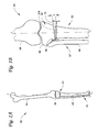
- Tibial and fibular osteotomies are described with reference to Figs. 1A and 1B , which show a lower limb 50 of a patient having a neutral axis 1-1 that includes a femur 54, a tibia 56 and a fibula 65.
- a tibial osteotomy can be performed to correct such a misalignment.
- a wedge opening 72 is formed in the tibia 56 when performing the tibial osteotomy.
- the wedge opening 72 can have a predetermined wedge angle ⁇ to correct the misalignment as illustrated in Figs. 1A and 1B .
- Figs. 1A and 1B illustrate a pre-op plan of the tibial osteotomy with a predetermined wedge angle ⁇ of nine degrees to correct the misalignment of the lower limb 50, but it is to be realized that the wedge angle ⁇ necessary to correct the misalignment can be any angle that is suitable for correcting a misalignment of the lower limb, and can depend on the condition of each individual patient.
- the tibial osteotomy is performed below a tibial tuberosity 52.
- a tibial osteotomy below the tibial tuberosity 52 is not recommended to patients. This is because tibial osteotomies above the tibial tuberosity 52 involve cutting into the cancellous bone (not shown), whereas tibial osteotomies below the tibial tuberosity 52 involves cutting into the cortical bone (not shown). It is generally accepted that the healing rates of the cortical bone is slower than that of the cancellous bone.
- tibial osteotomies below the tibial tuberosity 52 do not result in successful union of the bone following the procedure, and is not generally recommended to relatively older patients, for example, older patients who are in the fourth decade or more of their lives.
- the present inventors have found that the disclosed method that involves the use of the disclosed osteotomy guide device and/or the bone spacer guide device when performing a tibial osteotomy and/or a fibular osteotomy can lead to successful union of the bone following the procedure(s), even in older patients who are past the fourth decade of their lives.
- the disclosed methods also can lead to: (1) correction of misalignment; (2) regeneration of the bone in a relatively short time period as compared to that of conventional methods; (3) minimizing neurovascular bundle injury; (4) reducing stiffness in the knee after the procedure; (5) a smaller incision at the site of the respective osteotomies as compared to that of conventional methods; and (6) ease in performing the surgery; and (7) minimum disruption of the periosteum as compared to that of conventional methods which involve sawing.
- the surgical kit includes an osteotomy guide device and/or a bone spacer guide device and is used for performing a tibial osteotomy and/or a fibular osteotomy.
- the tibial osteotomy involves drilling of the tibia 56 through cortices (not shown) of the tibia 56.
- drilling of the tibia 56 can involve the use of a drill and a cutting tool as generally known in the art.
- An example of a drill that can be used has the following specifications.
- a power tool made by Stryker® that includes:
- An example of a drill bit that can be used has the following specifications: diameter of 2.0 mm, length 75 mm, and 2-flute for quick coupling.
- the cutting tool utilized can be a drill bit to create, for example, drill holes in the tibia 56.
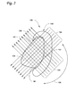
- Fig. 2 shows a top plan view of one embodiment of an osteotomy guide device 100 that can be included in the surgical kit.
- Fig. 2 also shows a cross-sectional top view taken across a horizontal axis 2-2 (see Fig. 1B ) of the tibia 56, and the osteotomy guide device 100 being fixed or mounted on the tibia 56.
- Fig. 2 further shows arrows 104, which represent directions of the drill paths through the osteotomy guide device 100 and the tibia 56, which will be discussed in further detail below.
- the osteotomy guide device 100 is configured to allow drilling to occur around the tibia 56, for example, as shown by an arrow 105 in Fig. 2 , and across a horizontal cross-sectional plane 101 of the tibia 56 so that the direction of each of the drill paths, e.g., as represented by each of the arrows 104, is substantially parallel to or on the same horizontal cross-sectional plane 101 of the tibia 56.
- the horizontal cross-sectional plane 101 is substantially perpendicular to the neutral axis 1-1.
- the term "substantially perpendicular to the neutral axis 1-1" means that the horizontal cross-sectional plane 101 is 90 ⁇ 10 degrees relative to the neutral axis 1-1.
- the term "the direction of each of the drill paths is substantially parallel to or on the same horizontal cross-sectional plane” means that the direction of each of the drill paths is 0 ⁇ 5 degrees relative to the horizontal cross-sectional plane 101.
- the drilling is conducted at a tibial osteotomy site 81, where the tibial osteotomy site 81, for example, is at a high tibial area and below the tibial tuberosity 52.
- the directions of the drill paths represented by the arrows 104 in Fig. 2 are shown to be either substantially parallel or substantially perpendicular to one another. However, it is to be realized that the directions of the drill paths can be any direction, so long as the directions are substantially parallel to or on the same horizontal cross-sectional plane 101 of the tibia 56.
- the osteotomy guide device 100 allows drilling around the tibia 56 to be conducted efficiently and accurately when performing the tibial osteotomy.
- the osteotomy guide device 100 has a base 102 having a central portion 125, an upwardly extending portion 106 and a downwardly extending portion 121.
- the central portion 125 is an elongated central portion that extends from a first end 109 to a second end 115, thereby defining a vertical axis 3-3 when the device 100 is viewed in top plan view.
- the upwardly extending portion 106 extends upwardly from the first end 109 of the elongated central portion 125.
- the downwardly extending portion 121 extends downwardly from the second end 115 of the elongated central portion 125.
- the upwardly extending portion 106, the elongated central portion 125 and the downwardly extending portion 121 of the base 102 is generally continuous as shown in Fig. 3 .
- the upwardly extending portion 106 is a latching portion that is in the shape of a hook.
- the base 102 has an inner side 131 and an outer side 134, and the latching portion 106 hooks toward the inner side 131 of the base 102 as shown in Fig. 2 .
- the latching portion 106 is dimensioned so that a tip 138 of the latching portion 106 can latch onto a surface 141 of the tibia 56.
- the latching portion 106 functions to fix the device 100 onto the tibia 56 so that the device 100 is in a fixed state as shown, for example, in Fig. 2 .
- the downwardly extending portion 121 is a flared portion that has a curvature relative to the vertical axis 3-3. In some examples, the flared portion 121 curves toward the inner side 131 of the device 100 relative to the vertical axis 3-3.
- the elongated central portion 125 and the flared portion 121 are generally continuous.
- the flared portion 121 curves towards the inner side 131 such that an outline 146 of the elongated central portion 125 and the flared portion 121 as viewed in top view generally follows at least a portion of an outline 151 of the tibia 56 as viewed in top view when the device 100 is in the fixed state as shown in Fig. 2 .
- the elongated central portion 125 and/or the flared portion 121 is in contact with the surface 141 of the tibia 56.
- the device contacts with and is in close fit with the lateral border of the tibia.
- the flared portion 121 curves at an angle ⁇ relative to the vertical axis 3-3.
- the angle ⁇ is an angle that allows the outline 146 of the elongated central portion 125 and the flared portion 121 to generally follow the outline 151 of the tibia 56 when the device 100 is in the fixed state as shown in Fig. 2 .
- the angle ⁇ can be about 0 to about 90 degrees.
- the angle ⁇ can be 0 ⁇ 15 to 90 ⁇ 15 degrees.
- the angle ⁇ can be 45 ⁇ 15 degrees.
- the angle ⁇ can be 45 ⁇ 10 degrees, in particular the angle can be 45 ⁇ 5 degrees, in particular be 45 degrees.
- the central portion 125 has a width w1 and the flared portion 121 has a width w2.
- w1 may be equal or different from w2.
- w1 and/or w2 can be about 0.5 cm to about 2 cm.
- w1 can be 10 mm and w2 can be 12 mm.
- the base 102 has a thickness h and a length L, and includes a plurality of passageways 161 that are formed through the thickness h of the base 102.
- the thickness h is about 0.5 cm to about 5 cm.
- the length L is about 60 mm to about 80 mm. Note that these values are only exemplary and can vary depending on, for example, a size of the tibia of the patient, the condition of the patient, etc.
- the plurality of passageways 161 include passageways 168 that are adapted for positioning a direction of the drilling.
- the term "passageways that are adapted for positioning the direction of the drilling” means that the passageways have a structure that allows a cutting tool, for example, a drill bit, to pass through each of the passageways so that drilling can occur in the direction of each of the respective passageways.
- the passageways 168 have respective inlets 172 and outlets 175, and the passageways 168 extend from the respective inlets 172 and the outlets 175 through the thickness h of the base 102.
- the inlets 172 are provided on the outer side 134 of the device 100 while the outlets 175 are provided on the inner side 131 of the device 100.
- the inlets 172 and the outlets 175 are provided along a median axis C-C of the base 102.
- the median axis C-C is an axis that is substantially parallel to a median plane 179 of the base 102.
- the median plane 179 is a plane that divides the base 102 into substantially two equal sides, one on a left side 182 of the median plane 179 and the other on a right side 184 of the median plane 179, so that a thickness h1 on the left side 182 of the median plane 179 and a thickness h2 on the right side 184 of the median plane 179 are substantially equal to one another.
- each of the passageways 168 extend from each of the respective inlets 172 to each of the respective outlets 175 in a direction that is substantially parallel to or on the horizontal cross-sectional plane 101 of the tibia 56 so that drilling can occur in a direction that is substantially parallel to or on the horizontal cross-sectional plane 101 of the tibia 56.
- the dimensions, the number, and the positions of the passageways 168 can be any dimensions, any number and any positions that are suitable for allowing a cutting tool to pass through and position the direction of the drilling.
- the base 102 can include about 3 to about 60 passageways 168.
- each of the passageways 168 can have a diameter of about 0.5 mm to about 8 mm.
- each of the passageways 168 can be spaced apart in about 1 mm to about 5 mm intervals.
- the passageways can have a diameter of about 2 to 3 mm, suitably 2.1, 2.3, 2.5 mm.
- the spaces between the passageways can be in the range 1 to 2 mm, suitably 1.5 to 2 mm, more suitably 1.9 mm.
- the plurality of passageways 161 further includes one or more passageways 192 that is adapted for inserting and/or positioning a stabilizing member, e.g., a wire, a pin or a screw, that is suitable for use during an osteotomy.
- a stabilizing member e.g., a wire, a pin or a screw
- the stabilizing member is a wire or a pin that is configured for fixation during osteotomy, e.g., a Kirschner wire (k-wire).
- the passageways 192 have inlets 202 and outlets 205.
- the inlets 202 are provided on the outer side 134 of the base 102 while the outlets 205 are provided on the inner side 131 of the base 102.
- the inlets 202 and the outlets 205 are provided along a first sagittal axis A-A and/or a second sagittal axis B-B of the base 102, which are substantially parallel to the median axis C-C shown in Fig. 5 .
- each of the inlets 202 is configured to receive a wire, pin or screw, e.g., a K-wire, and each of respective passageways 192 is configured to allow the wire, pin or screw to pass through each of the respective passageways 192 and exit out of each of the respective outlets 205.
- each of the passageways 192 is configured so as to allow the wire, pin or screw to help fix and/or stabilize the device 100 on the tibia 56.
- the dimensions, the number and the positions of the passageways 192 can be any dimensions, any number and any positions that are suitable for allowing a wire, pin or screw to pass through the base 102 and allow the wire, pin or screw to help fix and/or stabilize the device 100 on the tibia 56.
- the base 102 can include about 3 to about 60 passageways 192.
- each of the passageways 192 can have a diameter of about 0.5 mm to about 8 mm.
- each of the passageways 192 can be spaced apart in about 1 mm to about 5 mm intervals.
- the plurality of passageways 161 further includes one or more passageways 194 that is adapted for connecting a handle, for example, a butterfly screw. Details of an example of a handle that can be used will be discussed below.
- the passageways 194 have inlets 302 and outlets 305.
- the inlets 302 are provided on the outer side 134 of the base 102 while the outlets 305 are provided on the inner side 131 of the base 102.
- the inlets 302 and the outlets 305 are provided along the first sagittal axis A-A and/or the second sagittal axis B-B of the base 102, which are substantially parallel to the median axis C-C shown in Fig. 5 .
- each of the inlets 302 is configured to receive a handle, e.g., a butterfly screw, and each of the respective passageways 194 is configured to allow the handle to engage with the device 100 as described, for example, in detail below.
- each of the passageways 194 is configured so as to allow a user to handle the device 100.
- the osteotomy guide device 100 can be made of any material that is suitable for use in drilling through a tibia when performing a tibial osteotomy.
- the material can include, but is not limited to, metal.
- Figs. 10 and 11 show one example of a handle 220 that can be connected to the device 100 via the passageway 194.
- the handle 220 is an elongated member 223 having a first end 228 and a second end 231.
- the first end 228 has a gripping portion 241 that is in the shape of a dovetail and the second end 231 has a connecting portion 251 that includes threads 254 for gripping corresponding threads.
- internal threads (not shown) that can grip the threads 254 of the handle 220 are provided in one or more of the passageways 194 so as to engage the handle 220 with the device 100.
- the handle that can be used with the device 100 is not limited to the handle 220 illustrated in Figs. 10-11 , and can be any handle that is suitable for connecting with one or more of the passageways 194 and handling the device 100.
- the handle 220 can be made of any material that is suitable for use in positioning the osteotomy guide device 100.
- the material can include, but is not limited to, metal.
- the surgical kit further includes a bone spacer guide device.
- the bone spacer guide device is used to maintain a desired angle of a wedge opening 72 that is produced during the tibial osteotomy, for example, while a fixation plate is affixed on the tibia 56 (refer to Fig. 1B ).
- Figs. 12-18 show one embodiment of a bone spacer guide device 308 included in the surgical kit.
- the device 308 has a main body 310 having an upper side 361, a lower side 363, a thickness t and a length m.
- the thickness t is about 0.1 cm to about 10 cm
- the length m can be about 2 cm to about 20 cm. Note that these values are exemplary only, and can vary depending on, for example, a size of the tibia 56, the condition of the patient, etc.
- the length m can be about 5 to 6 cm, suitably 5.8 cm and t can be about 1 cm.
- the main body 310 includes a central portion 316 with two opposing side portions 319, 321 that extend outwardly in a horizontal direction from the central portion 316.
- the central portion 316 has a wedge member 324 that extends downwardly towards the lower side 363. In some examples, the wedge member 324 can be detached from the main body 310, as will be discussed further in detail below.
- the side portion 319 can include a groove portion 339 adjacent the central portion 316, and an arm portion 351 that extends outwardly in a horizontal direction from the groove portion 339.
- the side portion 321 has a structure that can be similar to that of the side portion 319, and can include a groove portion 334 and an arm portion 355 that extends outwardly from the groove portion 334.
- Each of the groove portions 334, 339 can be generally C-shaped or U-shaped as viewed in top view, as shown in Fig. 14 .
- each of the arm portions 351, 355 includes one or more passageways 344 that has an inlet 366 on the upper side 361 and a corresponding outlet (not shown) on the lower side 363.
- Each of the passageways 344 extend from the inlet 366 to the corresponding outlet through the thickness t of the main body 310.
- the inlet 366 is configured to receive a stabilizing member, e.g., a wire or a pin such as a k-wire, and each of the respective passageways 344 is configured to allow the wire, pin or screw to pass through each of the respective passageways 344 and exit out of each of the respective outlets.
- each of the passageways 344 is configured so as to allow the wire, pin or screw to help fix and/or stabilize the device 308 on the tibia 56.
- the dimensions, the number and the positions of the passageways 344 can be any dimensions, any number and any positions that are suitable for allowing a wire, pin or screw to pass through the main body 310 and allow the wire, pin or screw to help fix and/or stabilize the device 308 on the tibia 56.
- the main body 310 can include about 1 to about 20 passageways 344.
- each of the passageways 344 can have a diameter of about 0.2 mm to about 10 mm.
- each of the passageways 344 can be spaced apart in about 1 mm to about 5 mm intervals.
- each of the arm portions 351, 355 include four passageways 344. The passageways can be spaced apart by around 4 mm.
- the central portion 316 includes an opening 368 on the upper side 361 of the device 308.
- the opening 368 is configured to receive a handle, for example, the handle 220, so that the handle 220 can be connected to the device 308.
- the opening 368 includes internal threads (not shown) that can grip the threads 254 of the handle 220 so as to engage the handle 220 with the device 308.
- the handle that can be used with the device 308 is not limited to the handle 220 illustrated in Figs. 10-11 , and can be any handle that is suitable for connecting with the opening 368 and handling the device 308.
- the wedge member 324 can be detached from the main body 310.
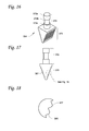
- Fig. 16 shows one example of the wedge member 324 that is detached from the main body 310.
- the wedge member 324 includes an attaching portion 372 and a wedge portion 375.
- the attaching portion 372 is generally cylindrical in shape, and has an upper cylindrical portion 372a, a central cylindrical portion 372b, and a lower cylindrical portion 372c. A diameter of the central cylindrical portion 372b is smaller than each of the diameters of the upper and lower cylindrical portions 372a, 372c.
- the attaching portion 372 can be inserted through a passageway 329 that is formed through the thickness t of the central portion 316. Note that the attaching portion 372 shown in Fig.
- the central cylindrical portion 372b has a smaller diameter, but it is to be realized that the cylindrically shaped attaching portion 372 can have one constant diameter such that it is not divided into different portions.
- the attaching portion 372 can be any shape that is suitable for attaching the wedge member 324 to the main body 310.
- the wedge suitably a triangular prism, can be about 4 to 12 mm, suitably 8 mm in width at a first (thick) end of the wedge and taper to 0.5 to 3 mm, suitably 1 mm at the second end (thin) end of the wedge.
- the distance between the base rectangle and apex edge (first to second end) can be about 5 to 20 mm, suitably 10 mm.
- the apex edge length can be about 5 to 20 mm, suitably 8 mm.
- a surface 377 of the wedge portion 375 has ridges 381 as shown in Figs. 17 and 18 .
- the ridges 381 are configured to provide a grip with a surface 378 (see Fig. 1B ) of the wedge opening 72 when the wedge portion 375 is inserted into the wedge opening 72, as described in detail in section VII.
- Figs. 16-18 show the surface 377 having ridges 381, it is to be realized that the surface can have any suitable texture for insertion of the wedge portion 375 into the wedge opening including, but not limited to, a smooth surface and/or ridges.
- the bone spacer guide device 308 can be made of any material that is suitable for maintaining the predetermined wedge angle ⁇ of the wedge opening 72 that is formed during the tibial osteotomy, for example, while a fixation plate is affixed on the tibia 56.
- the material can include, but is not limited to, metal or a polymer.
- the method generally involves performing both tibial and fibular osteotomies.
- the tibial osteotomy generally can involve drilling along at least a portion of the outline 151 of the tibia 56 as viewed in top plan view at the tibial osteotomy site 81 (see Fig. 1A ), where the drilling can occur across a horizontal cross-sectional plane 101 of the tibia 56 so that the direction of each of the drill paths is substantially parallel to or on the horizontal cross-sectional plane 101 of the tibia 56.
- the fibular osteotomy can performed at a fibular osteotomy site 79 (see Fig. 1A ), for example, at a distal third position of the fibula 65 as is generally known in the art.
- the fibular osteotomy can be conducted at approximately 45 ⁇ 15 degrees relative to the neutral axis 1-1.
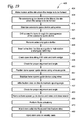
- Fig. 19 shows a flow chart of one example of a method 400 of using the osteotomy guide tool 100 and/or the bone spacer guide tool 310.
- the method 400 begins by making an incision at the tibial osteotomy site 81 (see Fig. 1A ) where the wedge opening 72 is to be formed in the tibia 56 (404). After the incision is made, the osteotomy guide device 100 is fixed on the tibia 56 at the site where the wedge opening 72 is to be formed so as to be in a fixed state (409).
- the osteotomy guide device 100 is fixed on the tibia 56 by latching the tip 138 of the device 100 on the surface 141 of the tibia 56.
- the handle 220 can be inserted in the passageway 194 to help position the device 100 on the tibia 56.
- the osteotomy guide device 100 is positioned at the tibial osteotomy site 81 where the wedge opening 72 is to be formed, and so that the median axis C-C is substantially parallel to the horizontal cross-sectional plane 101 of the tibia 56.
- the osteotomy guide device 100 is positioned so that at least a part of the central portion 125 and/or the flared portion 121 is in contact with the surface of the tibia 141 as shown in Figs. 2 and 20 .
- drilling can be performed along at least a portion of the outline 151 of the tibia 56, where the drilling occurs across the horizontal cross-sectional plane 101 of the tibia 56 so that the direction of each of the drill paths is substantially parallel to or on the same horizontal cross-sectional plane 101 of the tibia 56.
- the osteotomy guide device is stabilized using, for example, stabilizing members 488, for example, wires or a pins (415).
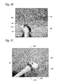
- the wires or pins 488 can be k-wires. Referring to Figs. 7 , 20 and 21 , in some examples, the wires or pins 488 are inserted through the passageways 192 of the device 100 so as to stabilize the position of the device 100 on the tibia 56.
- a drill 491 that has a cutting tool 496 for example, a drill bit
- An example of a drill that can be used has the following specifications.
- a power tool made by Stryker® that includes:
- An example of a drill bit that can be used has the following specifications: diameter of 2.0 mm, length 75 mm, and 2-flute for quick coupling.
- the drilling can be conducted through each of the passageways 168 that is provided along the median axis C-C so that drilling can occur around the tibia 56, and across the horizontal cross-sectional plane 101 of the tibia 56 so that the direction of each of the drill paths is substantially parallel to or on the same horizontal cross-sectional plane 101 of the tibia 56.
- the drilling can be conducted from a medial side 53 (see Fig. 1B ) to a lateral side 57 (see Fig. 1B ), for example, depending on whether drilling is being conducted on a right or left lower limb.
- the drilling is conducted on a patient that requires correction of a varus deformity.
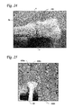
- Fig. 24 shows drill holes 498 that are formed as a result of the drilling in step 421. Note that the drill holes 498 are aligned on an axis 4-4 that is substantially parallel to or on the horizontal cross-sectional plane 101 of the tibia 56. In some examples, the horizontal cross-sectional plane 101 is substantially perpendicular to the neutral axis 1-1 so that each of the directions of the drill holes that is formed is substantially perpendicular to the neutral axis 1-1.
- the stabilizing members 488 are inserted into the tibia 56.
- two k-wires 488a are inserted in a direction that is perpendicular to the neutral axis 1-1 (see Fig. 1A ), and two other k-wires 488b are inserted in a direction that is perpendicular to the direction of insertion of the two-wires 488a.
- each of the k-wires 488a, 488b is inserted at each side of the axis 4-4 at a corresponding location.
- Each of the two k-wires 488a is parallel to one another, and each of the two k-wires 488b is parallel to one another.
- the k-wires 488a and/or the k-wires 488b function as a guide to avoid and/or at least reduce mal-rotation and angular deformity relative to the neutral axis 1-1 during the osteotomy process.
- the tibia 56 is cracked open along the drill holes 498 so as to form the wedge opening 72.
- Figs. 1A and 1B show a left limb and a hinge 58 of the wedge opening 72 is shown to be on the lateral side 57.
- the wedge opening would be a mirror image of the wedge opening 72 shown in Fig. 1B .
- the wedge opening 72 can be formed using procedures generally known in the art.
- the drill holes 498 can be connected to create an osteotomy.
- an x-ray of the tibia 56 taken beforehand can be used to check the position of the osteotomy.
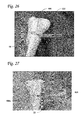
- the osteotomy can be formed using an osteotome or bone chisel 502 as shown in Fig. 26 .
- the osteotome or bone chisel 502 that is used can be any osteotome or bone chisel suitable for use when performing an osteotomy.
- An example of an osteotome or bone spreader that can be used has the following specifications.
- An osteotome made by TomoFixTM having the following configurations:
- an angular bone spreader 505 can be inserted into the opening.
- the angular bone spreader 505 that can be used can be any angular bone spreader that is conventionally used when performing an osteotomy.
- An example of an angular bone spreader 505 that can be used has the following specifications.
- the angular bone spreader 505 then can be used to crank open the opening so as to form the wedge opening 72 (see Fig. 27 ). In some examples, the angular bone spreader 505 can be used to open the wedge opening 72 to the predetermined wedge angle ⁇ .
- the alignment of the wedge opening 72 and the wedge angle ⁇ can be checked with reference to the x-ray of the tibia 56 and/or the two pairs of k-wires 488a, 488b.
- the two pairs of k-wires 488a, 488b can be checked to determine whether they are maintaining a perpendicular position relative to one another.
- the bone spacer guide device 308 can be provided on the tibia 56.
- the bone spacer guide device 308 is provided on the tibia 56 to maintain the wedge angle ⁇ .
- the bone spacer guide device 308 can be provided on the tibia 56 by inserting the wedge portion 375 into the wedge opening 72.
- the bone spacer guide device 308 is positioned so that each of the k-wires 488b is provided in an opening 369, 370 of the respective groove portions 334, 339 of the device 308.
- additional stabilizing members 508 for examples, wires, pins or screws, are inserted through the passageways 344 of the device 308 so as to stabilize the device 308 on the tibia 56.
- the stabilizing members 508 can be k-wires.
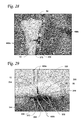
- a fixation plate 510 is affixed to the tibia 56 so as to maintain the wedge angle ⁇ (see Figs. 30 and 31 ).
- the fixation plate 510 that can be used can be any fixation plate that is typically used when performing an osteotomy or any plate that can be used to hold a fracture.
- An example of a fixation plate 510 can have the following specifications.
- LCP medial proximal tibial plate 4.5 having 6 to 12 holes, a length of 142mm and made of pure titanium.
- the position of the fixation plate 510 can be checked with reference to the x-ray of the tibia 56.
- the two pairs of k-wires 488a, 488b can be checked to determine whether they are maintaining a perpendicular position relative to one another. Note that the k-wires 488b may diverge from one another due to the formation of the wedge opening 72 (see Fig. 31 ).
- the bone spacer guide device 308, the k-wires 488a, 488b and 508 are removed, and the wound is closed, for example, by suturing as generally known in the art.
- a fibular osteotomy 469 is performed at the fibular osteotomy site 79, for example, at a distal third position of the fibula 65 (see Fig. 1A ) as is generally known in the art.
- the fibular osteotomy is conducted at approximately 45 ⁇ 15 degrees relative to the neutral axis 1-1.
- the fibular osteotomy 469 can be performed at any time during the method 400, and is not limited to before or after performing the tibial osteotomy.
- stem cells that were previously harvested are injected into the tibial osteotomy site 81 and/or the fibular osteotomy site 79.
- the stem cells are harvested seven days prior to when the method 400 is performed.
- the stem cells used can be, for example, peripheral blood stem cells (PBSCs).
- PBSCs are autologous.
- the PBSCs are positive for CD34.
- the stem cells are injected in an amount sufficient to repair the osteotomy site 79, 81 so that there is successful union of the bone at the osteotomy site 79, 81.
- the effective amount of stem cells can be about 0.2 ⁇ 0.1x10 6 ⁇ 1 to about 8 ⁇ 1x10 6 ⁇ 2 of stem cells.
- Fig. 32 One example of how the stem cells are harvested and stored is illustrated in Fig. 32 and the various steps 1-12 described below. Note that the specific amounts employed for the mixtures produced are exemplary only and it is to be realized that the amounts discussed below can vary as to scale and different amounts may be employed.
- an amount of harvested stem cells for example, about 0.2 ⁇ 0.1x10 6 ⁇ 1 to about 8 ⁇ 1x10 6 ⁇ 2 of stem cells contained in two 4ml vials, can be set aside and stored at a temperature of about 4°C for immediate use.
- the PBSCs are positive for CD34.
- the stem cells can be PBSCs.
- the PBSCs are are positive for CD34.
- the PBSCs can be autologous.
- a storage mixture of saline (cooled from a refrigerator or an ice water bath at about 4°C), plasma, dimethyl-disulphoxide (DMSO), and PBSCs is prepared.
- a 100ml mixture the following are used: 10ml of saline; 10ml of plasma; 10ml of DMSO; and 70ml of PBSCs.
- a 208ml mixture includes 20ml of saline, 20ml of plasma, 20ml of DMSO, and 148ml of PBSCs (150ml also may be used for a 210ml total mixture).
- step 2 shows the mixture of saline with DMSO that is kept in the refrigerator or an ice water bath before use at about 4°C.
- step 3 shows obtaining 20ml of the plasma from the patient's source.
- Step 4 shows the mixing of the plasma with the mixture of saline and DMSO.
- Steps 5 and 6 show that, prior to addition of the PBSCs to the mixture, about 1ml of the PBSC source (e.g. 152 ml) is taken for a fresh sample cell count and 3ml of the PBSC source is taken for blood culture, which leaves 148 ml of the PBSC source.
- Steps 5 and 6 are quality control steps during the process.
- Step 7 shows the mixing of the mixture of plasma, saline, and DMSO with the remaining PBSC source (e.g. 148 ml).
- step 8 another quality control step can be performed where 1ml is taken for cell count and 3ml is taken for blood culture.
- a sterile tube rack is prepared.
- 20 to 80 cryo-tubes or vials are prepared with labelling (sterilised) and each tube/vial is filled with 4ml of the mixture.
- the vials are prepared with laminar flow (e.g. Biosafety cabinet Class 100 with or without fan on), where ultraviolet (UV) light has been on for about 10 minutes to 1 hour before use. That is, the UV light is turned off during the preparation or filling of the vials, and then the UV light is turned on to re-sterilize the compartment before using.
- laminar flow e.g. Biosafety cabinet Class 100 with or without fan on
- the vials (e.g. about 20 to 80 vials at a time), are contained in a control rate freezer or any method providing a controlled rate during freezing from room temperature to about -80°C for approximately 45 minutes.
- the vial samples are subject to freezing at -196°C.
- 4 ml of the vial samples are frozen using liquid nitrogen (LN 2 ), where they can be thawed for later blood culturing and cell count testing.
- the frozen vials can be thawed, for example, after the second day of freezing.
- second day means the day after the vials were frozen in liquid nitrogen. For example, if the vials were frozen in liquid nitrogen on Monday, the second day would be Tuesday, at which time the vials can be taken out and thawed, so that the peripheral blood stem cell contents can be sent for blood culture.
- Table 1 below shows viability of the stem cell samples prepared in accordance with the process of Fig. 32 .
- Table 1 Sample for Peripheral Blood Stem Cells (4 mls) Fresh Fresh with DMSO Frozen CD34+ (10 6 cells) Viability % CD34+ (10 6 cells) Viability % CD34+ (10 6 cells) Viability % 4.22 99.30 2.89 92.40 5.04 83.50 4.05 99.10 2.87 94.70 2.76 88.30 1.73 98.80 1.38 90.40 1.18 78.60 3.37 98.30 2.28 92.50 2.12 81.60 2.96 99.10 2.05 95.40 1.92 81.50 2.3 99.30 1.64 94.40 1.42 86.80 1.52 98.80 1.01 91.80 0.95 84.90 3.59 99.30 2.67 93.50 2.51 85.80 0.93 99.40 0.50 97.60 0.44 90.90 7.55 99.40 5.34 87.90 4.91
- Table 1 provides a summary of cell count and yield for the following: fresh samples, fresh samples with DMSO, and post thaw of frozen samples, e.g. produced according to Fig 32 .
- fresh samples fresh samples with DMSO
- post thaw of frozen samples e.g. produced according to Fig 32 .
- the cell viability of known frozen samples is reported to be approximately 80% and fresh samples with DMSO are between 69% to 80%.
- the samples are far superior with frozen samples, for example having a viability of over 83% on average and with fresh samples (w/ DMSO) having a viability of over 92% on average (lowest 84.5%).
- the results reported in Table 1 show that the process of Fig.32 can provide good viability samples and a further improvement over known viability studies.
- the stem cells can be injected into the fibular osteotomy site 79 and/or the tibial osteotomy site 81 on a weekly basis (480).
- the stem cells used can be, for example, the same type of cells used in step 473 as discussed above.
- the amount of stem cells injected can be the same amount of stem cells as in step 473 as discussed above.
- the stem cells are injected once a week. In some examples, the stem cells are injected on a weekly basis, for example, once a week, for about one to about five weeks after step 473 is performed.
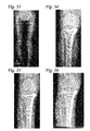
- Figs. 33-36 show an example of a patient who was subjected to the disclosed method.
- the patient is 50 years old.
- Fig. 33 shows an X-ray image of the right and left lower limbs of the patient.
- the right knee has a varus deformity.
- the left knee had a varus deformity but was treated by subjecting to a tibial osteotomy employing conventional methods.
- Figs. 1A and 1B show the pre-operation plan to obtain the angle of correction for the size of the wedge opening of the right knee shown in Fig. 33.
- Fig. 34 shows an X-ray image of the right knee post-operation.
- the X-ray image shows an anteroposterio view of the right knee.
- FIG. 35 shows the same view of the right knee at 6 weeks post-operation.
- the X-ray shows bone callous formation at the osteotomy site.
- Fig. 36 shows the same view of the right knee at 5 months post-operation.
- the X-ray shows good bone callous formation.
Landscapes
- Health & Medical Sciences (AREA)
- Life Sciences & Earth Sciences (AREA)
- Surgery (AREA)
- Orthopedic Medicine & Surgery (AREA)
- Animal Behavior & Ethology (AREA)
- Biomedical Technology (AREA)
- Veterinary Medicine (AREA)
- Public Health (AREA)
- General Health & Medical Sciences (AREA)
- Engineering & Computer Science (AREA)
- Heart & Thoracic Surgery (AREA)
- Nuclear Medicine, Radiotherapy & Molecular Imaging (AREA)
- Medical Informatics (AREA)
- Molecular Biology (AREA)
- Oral & Maxillofacial Surgery (AREA)
- Dentistry (AREA)
- Neurology (AREA)
- Cell Biology (AREA)
- Medicinal Chemistry (AREA)
- Hematology (AREA)
- Biotechnology (AREA)
- Epidemiology (AREA)
- Developmental Biology & Embryology (AREA)
- Immunology (AREA)
- Virology (AREA)
- Zoology (AREA)
- Chemical & Material Sciences (AREA)
- Pharmacology & Pharmacy (AREA)
- Transplantation (AREA)
- Physical Education & Sports Medicine (AREA)
- Surgical Instruments (AREA)
Applications Claiming Priority (1)
| Application Number | Priority Date | Filing Date | Title |
|---|---|---|---|
| MYPI2013701639A MY165689A (en) | 2013-09-12 | 2013-09-12 | Osteotomy below the tibial tuberosity by multiple drilling |
Publications (3)
| Publication Number | Publication Date |
|---|---|
| EP2848210A1 true EP2848210A1 (fr) | 2015-03-18 |
| EP2848210B1 EP2848210B1 (fr) | 2019-02-06 |
| EP2848210B8 EP2848210B8 (fr) | 2019-05-15 |
Family
ID=49237049
Family Applications (1)
| Application Number | Title | Priority Date | Filing Date |
|---|---|---|---|
| EP13185055.4A Active EP2848210B8 (fr) | 2013-09-12 | 2013-09-18 | Guide d'ostéotomie |
Country Status (3)
| Country | Link |
|---|---|
| US (1) | US9486228B2 (fr) |
| EP (1) | EP2848210B8 (fr) |
| MY (1) | MY165689A (fr) |
Families Citing this family (16)
| Publication number | Priority date | Publication date | Assignee | Title |
|---|---|---|---|---|
| US9833245B2 (en) * | 2014-09-29 | 2017-12-05 | Biomet Sports Medicine, Llc | Tibial tubercule osteotomy |
| US11504139B2 (en) | 2015-09-02 | 2022-11-22 | Wright Medical Technology, Inc. | Chevron osteotomy tools and methods |
| RU2696243C2 (ru) * | 2017-12-28 | 2019-07-31 | Общество с ограниченной ответственностью "ОСТЕОМЕД-М" (ООО "ОСТЕОМЕД-М") | Комплект для проведения высокой тибиальной остеотомии и способ исправления варусной деформации коленного сустава при помощи мини-инвазивной операции |
| RU2698872C2 (ru) * | 2017-12-28 | 2019-08-30 | Общество с ограниченной ответственностью "ОСТЕОМЕД-М" (ООО "ОСТЕОМЕД-М") | Устройство для фиксации фрагментов кости при высокой тибиальной коррегирующей остеотомии |
| US11517333B2 (en) | 2018-08-24 | 2022-12-06 | Laboratoires Bodycad Inc. | Predrilling guide for knee osteotomy fixation plate |
| WO2020037420A1 (fr) * | 2018-08-24 | 2020-02-27 | Laboratoires Bodycad Inc. | Kit chirurgical pour ostéotomies du genou et procédé de planification préopératoire correspondant |
| US11589876B2 (en) * | 2018-08-24 | 2023-02-28 | Laboratoires Bodycad Inc. | Surgical guide assembly for performing a knee osteotomy procedure |
| WO2020037419A1 (fr) * | 2018-08-24 | 2020-02-27 | Laboratoires Bodycad Inc. | Outils chirurgicaux spécifiques au patient pour ostéotomies du genou |
| GB2591364B (en) | 2018-08-24 | 2023-01-04 | Laboratoires Bodycad Inc | Patient-specific fixation plate with wedge member |
| US11701150B2 (en) | 2018-08-24 | 2023-07-18 | Laboratoires Bodycad Inc. | Patient-specific fixation plate with spacing elements |
| USD948719S1 (en) | 2019-10-21 | 2022-04-12 | Laboratoires Bodycad Inc. | Posterior stabilizer for an osteotomy plate |
| USD943100S1 (en) | 2020-02-18 | 2022-02-08 | Laboratoires Bodycad Inc. | Osteotomy plate |
| US12343045B2 (en) | 2020-03-30 | 2025-07-01 | Wright Medical Technology, Inc. | Targeting guide and associated method |
| CN112842455B (zh) * | 2020-12-31 | 2022-05-17 | 北京长木谷医疗科技有限公司 | 全膝关节置换手术用胫骨导板及其使用方法 |
| US12383286B2 (en) | 2021-03-02 | 2025-08-12 | Wright Medical Technology, Inc. | Minimally invasive surgical tools and systems |
| US20240307071A1 (en) * | 2023-03-15 | 2024-09-19 | Mack Jay GROVES, IV | Bone cutting tool for reduction of planar deformities of variable magnitude |
Citations (6)
| Publication number | Priority date | Publication date | Assignee | Title |
|---|---|---|---|---|
| WO1996024295A1 (fr) * | 1995-02-07 | 1996-08-15 | Jenkins Joseph R Jr | Systeme ameliore d'osteotomie tibiale |
| US5722978A (en) * | 1996-03-13 | 1998-03-03 | Jenkins, Jr.; Joseph Robert | Osteotomy system |
| US20080177306A1 (en) * | 2004-10-25 | 2008-07-24 | Lanx, Inc. | Spinal implants and methods |
| US20080262500A1 (en) * | 2007-04-19 | 2008-10-23 | Howmedica Osteonics Corp. | Cutting guide with internal distraction |
| US20090157190A1 (en) * | 2007-12-13 | 2009-06-18 | Howmedica Inc. | Osteotomy spacer |
| US20110213376A1 (en) * | 2010-02-26 | 2011-09-01 | Biomet Sports Medicine, Llc | Patient-Specific Osteotomy Devices and Methods |
Family Cites Families (24)
| Publication number | Priority date | Publication date | Assignee | Title |
|---|---|---|---|---|
| DE4344113A1 (de) | 1993-12-23 | 1995-06-29 | Metallgesellschaft Ag | Verfahren zur Reinigung von Abgasen der Abfallverbrennung |
| US5620448A (en) | 1995-03-24 | 1997-04-15 | Arthrex, Inc. | Bone plate system for opening wedge proximal tibial osteotomy |
| US5601565A (en) * | 1995-06-02 | 1997-02-11 | Huebner; Randall J. | Osteotomy method and apparatus |
| US5980526A (en) * | 1997-02-12 | 1999-11-09 | Orthopaedic Innovations, Inc. | Wedge osteotomy device including a guide for controlling osteotomy depth |
| US6203546B1 (en) | 1999-07-27 | 2001-03-20 | Macmahon Edward B | Method and apparatus for medial tibial osteotomy |
| US6190390B1 (en) * | 1999-10-29 | 2001-02-20 | Howmedica Osteonics Corp. | Apparatus and method for creating a dome tibial osteotomy |
| US6796986B2 (en) | 2001-03-29 | 2004-09-28 | David W. Duffner | Adjustable tibial osteotomy jig and method |
| JP2005518240A (ja) * | 2002-02-26 | 2005-06-23 | ネムコムド リミテッド | 膝蓋骨切除ガイド |
| CA2474967C (fr) * | 2002-03-05 | 2009-09-29 | Nemcomed, Inc. | Methode d'arthroplastie totale du genou a effraction minimale |
| US7112204B2 (en) * | 2003-02-06 | 2006-09-26 | Medicinelodge, Inc. | Tibial tubercle osteotomy for total knee arthroplasty and instruments and implants therefor |
| US8388690B2 (en) * | 2003-10-03 | 2013-03-05 | Linvatec Corporation | Osteotomy system |
| ATE422847T1 (de) * | 2004-12-08 | 2009-03-15 | Perception Raisonnement Action | Vorrichtung zur positionierung einer knochenschnittführung |
| CA2597220C (fr) * | 2005-02-08 | 2014-04-01 | Ibalance Medical, Inc. | Procede et appareil de formation d'une ouverture de type coin dans un os pour osteotomie d'ouverture |
| US20080077151A1 (en) * | 2006-01-23 | 2008-03-27 | Bob Kring | Method and Apparatus for Restraining a Patient's Leg During Leg Surgical and Interventional Procedures |
| US8241292B2 (en) * | 2006-06-30 | 2012-08-14 | Howmedica Osteonics Corp. | High tibial osteotomy system |
| US8685034B2 (en) * | 2006-08-10 | 2014-04-01 | Stryker Trauma Gmbh | Distal targeting device |
| US20080195099A1 (en) | 2007-02-13 | 2008-08-14 | The Brigham And Women's Hospital, Inc. | Osteotomy system |
| WO2010048288A1 (fr) | 2008-10-21 | 2010-04-29 | Ibalance Medical, Inc. | Procédé et appareil pour réaliser une ostéotomie tibiale haute d'ouverture à coin |
| US8475463B2 (en) * | 2009-04-13 | 2013-07-02 | George J. Lian | Systems and instrumentalities for use in total ankle replacement surgery |
| US20100274254A1 (en) * | 2009-04-22 | 2010-10-28 | Pascal Boileau | Surgical instrumentation for fitting an osteosynthesis nail |
| KR20120104580A (ko) * | 2009-11-20 | 2012-09-21 | 니 크리에이션스, 엘엘씨 | 관절 복원을 위한 내비게이션 및 위치결정 기기 |
| US9241745B2 (en) * | 2011-03-07 | 2016-01-26 | Biomet Manufacturing, Llc | Patient-specific femoral version guide |
| US8915923B2 (en) * | 2011-09-28 | 2014-12-23 | Depuy (Ireland) | Patella resection assembly |
| EP2884910A4 (fr) * | 2012-08-09 | 2016-06-01 | Smith & Nephew Inc | Arthroplastie totale du genou adaptée à un patient |
-
2013
- 2013-09-12 MY MYPI2013701639A patent/MY165689A/en unknown
- 2013-09-18 EP EP13185055.4A patent/EP2848210B8/fr active Active
- 2013-10-07 US US14/047,236 patent/US9486228B2/en active Active
Patent Citations (6)
| Publication number | Priority date | Publication date | Assignee | Title |
|---|---|---|---|---|
| WO1996024295A1 (fr) * | 1995-02-07 | 1996-08-15 | Jenkins Joseph R Jr | Systeme ameliore d'osteotomie tibiale |
| US5722978A (en) * | 1996-03-13 | 1998-03-03 | Jenkins, Jr.; Joseph Robert | Osteotomy system |
| US20080177306A1 (en) * | 2004-10-25 | 2008-07-24 | Lanx, Inc. | Spinal implants and methods |
| US20080262500A1 (en) * | 2007-04-19 | 2008-10-23 | Howmedica Osteonics Corp. | Cutting guide with internal distraction |
| US20090157190A1 (en) * | 2007-12-13 | 2009-06-18 | Howmedica Inc. | Osteotomy spacer |
| US20110213376A1 (en) * | 2010-02-26 | 2011-09-01 | Biomet Sports Medicine, Llc | Patient-Specific Osteotomy Devices and Methods |
Non-Patent Citations (2)
| Title |
|---|
| DAVID BERZ ET AL: "Cryopreservation of hematopoietic stem cells", AMERICAN JOURNAL OF HEMATOLOGY, vol. 82, no. 6, 1 June 2007 (2007-06-01), pages 463 - 472, XP055107084, ISSN: 0361-8609, DOI: 10.1002/ajh.20707 * |
| KATAYAMA ET AL., BONE MARROW TRANSPLANTATION, vol. 19, 1997, pages 283 - 287 |
Also Published As
| Publication number | Publication date |
|---|---|
| US20150071885A1 (en) | 2015-03-12 |
| EP2848210B8 (fr) | 2019-05-15 |
| EP2848210B1 (fr) | 2019-02-06 |
| US9486228B2 (en) | 2016-11-08 |
| MY165689A (en) | 2018-04-20 |
Similar Documents
| Publication | Publication Date | Title |
|---|---|---|
| EP2848210B1 (fr) | Guide d'ostéotomie | |
| Rozbruch et al. | Distraction osteogenesis for nonunion after high tibial osteotomy | |
| Kaspar et al. | Angle stable locking reduces interfragmentary movements and promotes healing after unreamed nailing: study of a displaced osteotomy model in sheep tibiae | |
| Kirane et al. | Precision of the PRECICE® internal bone lengthening nail | |
| Whipple | Stabilization of the fractured scaphoid under arthroscopic control | |
| Tsuchiya et al. | Deformity correction followed by lengthening with the Ilizarov method | |
| Rogers et al. | Computer hexapod assisted orthopaedic surgery (CHAOS) in the correction of long bone fracture and deformity | |
| Buchman et al. | Unique rodent model of distraction osteogenesis of the mandible | |
| Yoon et al. | Efficacy of staged surgery in the treatment of open tibial fractures with severe soft tissue injury and bone defect | |
| Thaller et al. | Surgical techniques for lengthening and deformity correction of the tibia with lengthening nails | |
| Akkina et al. | Techniques for maxillomandibular fixation: Old and new | |
| Schoenfeld et al. | Valgus osteotomy of the proximal femur with sliding hip screw for the treatment of femoral neck nonunions: the technique, a case series, and literature review | |
| Hanf-Osetek et al. | Tibial shaft fractures in children: flexible intramedullary nailing in growing children especially weighing 50 kg (110 lbs) or more | |
| Richardson | Complications of orthopaedic surgery in horses | |
| Sala et al. | Evaluation of an endoscopic procedure for the treatment of docking site nonunion | |
| Aksoy et al. | Treatment of complicated pediatric femoral fractures with titanium elastic nail | |
| Easley et al. | Ankle arthrodesis using ring external fixation | |
| Frigg et al. | Can complications of titanium elastic nailing with end cap for clavicular fractures be reduced? | |
| Behrens et al. | Deformity correction and reconstructive procedures using percutaneous techniques. | |
| RU2384305C1 (ru) | Способ двухвинтовой фиксации перелома зубовидного отростка с2 позвонка и устройство для введения, по меньшей мере, одной спицы для двухвинтовой фиксации перелома зубовидного отростка с2 позвонка | |
| Auer et al. | Displacement osteotomies/ostectomies in the horse. | |
| RU161985U1 (ru) | Фиксатор для остеосинтеза переломов наружного надмыщелка плечевой кости | |
| Mehdian et al. | Cervical osteotomy in ankylosing spondylitis | |
| de Agustín-Asensio et al. | Titanium miniplates for the surgical correction of pectus excavatum1 | |
| Kofod et al. | Unilateral mandibular ramus elongation by intraoral distraction osteogenesis |
Legal Events
| Date | Code | Title | Description |
|---|---|---|---|
| PUAI | Public reference made under article 153(3) epc to a published international application that has entered the european phase |
Free format text: ORIGINAL CODE: 0009012 |
|
| 17P | Request for examination filed |
Effective date: 20130918 |
|
| AK | Designated contracting states |
Kind code of ref document: A1 Designated state(s): AL AT BE BG CH CY CZ DE DK EE ES FI FR GB GR HR HU IE IS IT LI LT LU LV MC MK MT NL NO PL PT RO RS SE SI SK SM TR |
|
| AX | Request for extension of the european patent |
Extension state: BA ME |
|
| STAA | Information on the status of an ep patent application or granted ep patent |
Free format text: STATUS: EXAMINATION IS IN PROGRESS |
|
| 17Q | First examination report despatched |
Effective date: 20170313 |
|
| GRAP | Despatch of communication of intention to grant a patent |
Free format text: ORIGINAL CODE: EPIDOSNIGR1 |
|
| STAA | Information on the status of an ep patent application or granted ep patent |
Free format text: STATUS: GRANT OF PATENT IS INTENDED |
|
| INTG | Intention to grant announced |
Effective date: 20180910 |
|
| GRAS | Grant fee paid |
Free format text: ORIGINAL CODE: EPIDOSNIGR3 |
|
| GRAA | (expected) grant |
Free format text: ORIGINAL CODE: 0009210 |
|
| STAA | Information on the status of an ep patent application or granted ep patent |
Free format text: STATUS: THE PATENT HAS BEEN GRANTED |
|
| AK | Designated contracting states |
Kind code of ref document: B1 Designated state(s): AL AT BE BG CH CY CZ DE DK EE ES FI FR GB GR HR HU IE IS IT LI LT LU LV MC MK MT NL NO PL PT RO RS SE SI SK SM TR |
|
| REG | Reference to a national code |
Ref country code: GB Ref legal event code: FG4D |
|
| REG | Reference to a national code |
Ref country code: CH Ref legal event code: EP Ref country code: AT Ref legal event code: REF Ref document number: 1094367 Country of ref document: AT Kind code of ref document: T Effective date: 20190215 |
|
| REG | Reference to a national code |
Ref country code: IE Ref legal event code: FG4D |
|
| REG | Reference to a national code |
Ref country code: DE Ref legal event code: R096 Ref document number: 602013050443 Country of ref document: DE |
|
| REG | Reference to a national code |
Ref country code: CH Ref legal event code: PK Free format text: BERICHTIGUNGEN |
|
| REG | Reference to a national code |
Ref country code: CH Ref legal event code: NV Representative=s name: MURGITROYD AND COMPANY, CH |
|
| RAP2 | Party data changed (patent owner data changed or rights of a patent transferred) |
Owner name: SAW, KHAY YONG Owner name: JEE, CAROLINE SIEW YOKE Owner name: NG, REZA CHING SOONG |
|
| RIN2 | Information on inventor provided after grant (corrected) |
Inventor name: NG, REZA CHING SOONG Inventor name: JEE, CAROLINE SIEW YOKE Inventor name: SAW, KHAY YONG |
|
| REG | Reference to a national code |
Ref country code: DE Ref legal event code: R082 Ref document number: 602013050443 Country of ref document: DE Representative=s name: MURGITROYD & COMPANY, DE |
|
| REG | Reference to a national code |
Ref country code: CH Ref legal event code: PK Free format text: BERICHTIGUNG B8 Ref country code: SE Ref legal event code: TRGR |
|
| REG | Reference to a national code |
Ref country code: NL Ref legal event code: FP |
|
| REG | Reference to a national code |
Ref country code: LT Ref legal event code: MG4D |
|
| PG25 | Lapsed in a contracting state [announced via postgrant information from national office to epo] |
Ref country code: PT Free format text: LAPSE BECAUSE OF FAILURE TO SUBMIT A TRANSLATION OF THE DESCRIPTION OR TO PAY THE FEE WITHIN THE PRESCRIBED TIME-LIMIT Effective date: 20190606 Ref country code: NO Free format text: LAPSE BECAUSE OF FAILURE TO SUBMIT A TRANSLATION OF THE DESCRIPTION OR TO PAY THE FEE WITHIN THE PRESCRIBED TIME-LIMIT Effective date: 20190506 Ref country code: FI Free format text: LAPSE BECAUSE OF FAILURE TO SUBMIT A TRANSLATION OF THE DESCRIPTION OR TO PAY THE FEE WITHIN THE PRESCRIBED TIME-LIMIT Effective date: 20190206 Ref country code: LT Free format text: LAPSE BECAUSE OF FAILURE TO SUBMIT A TRANSLATION OF THE DESCRIPTION OR TO PAY THE FEE WITHIN THE PRESCRIBED TIME-LIMIT Effective date: 20190206 |
|
| REG | Reference to a national code |
Ref country code: AT Ref legal event code: MK05 Ref document number: 1094367 Country of ref document: AT Kind code of ref document: T Effective date: 20190206 |
|
| PG25 | Lapsed in a contracting state [announced via postgrant information from national office to epo] |
Ref country code: HR Free format text: LAPSE BECAUSE OF FAILURE TO SUBMIT A TRANSLATION OF THE DESCRIPTION OR TO PAY THE FEE WITHIN THE PRESCRIBED TIME-LIMIT Effective date: 20190206 Ref country code: RS Free format text: LAPSE BECAUSE OF FAILURE TO SUBMIT A TRANSLATION OF THE DESCRIPTION OR TO PAY THE FEE WITHIN THE PRESCRIBED TIME-LIMIT Effective date: 20190206 Ref country code: BG Free format text: LAPSE BECAUSE OF FAILURE TO SUBMIT A TRANSLATION OF THE DESCRIPTION OR TO PAY THE FEE WITHIN THE PRESCRIBED TIME-LIMIT Effective date: 20190506 Ref country code: LV Free format text: LAPSE BECAUSE OF FAILURE TO SUBMIT A TRANSLATION OF THE DESCRIPTION OR TO PAY THE FEE WITHIN THE PRESCRIBED TIME-LIMIT Effective date: 20190206 Ref country code: GR Free format text: LAPSE BECAUSE OF FAILURE TO SUBMIT A TRANSLATION OF THE DESCRIPTION OR TO PAY THE FEE WITHIN THE PRESCRIBED TIME-LIMIT Effective date: 20190507 Ref country code: IS Free format text: LAPSE BECAUSE OF FAILURE TO SUBMIT A TRANSLATION OF THE DESCRIPTION OR TO PAY THE FEE WITHIN THE PRESCRIBED TIME-LIMIT Effective date: 20190606 |
|
| PG25 | Lapsed in a contracting state [announced via postgrant information from national office to epo] |
Ref country code: EE Free format text: LAPSE BECAUSE OF FAILURE TO SUBMIT A TRANSLATION OF THE DESCRIPTION OR TO PAY THE FEE WITHIN THE PRESCRIBED TIME-LIMIT Effective date: 20190206 Ref country code: SK Free format text: LAPSE BECAUSE OF FAILURE TO SUBMIT A TRANSLATION OF THE DESCRIPTION OR TO PAY THE FEE WITHIN THE PRESCRIBED TIME-LIMIT Effective date: 20190206 Ref country code: RO Free format text: LAPSE BECAUSE OF FAILURE TO SUBMIT A TRANSLATION OF THE DESCRIPTION OR TO PAY THE FEE WITHIN THE PRESCRIBED TIME-LIMIT Effective date: 20190206 Ref country code: IT Free format text: LAPSE BECAUSE OF FAILURE TO SUBMIT A TRANSLATION OF THE DESCRIPTION OR TO PAY THE FEE WITHIN THE PRESCRIBED TIME-LIMIT Effective date: 20190206 Ref country code: DK Free format text: LAPSE BECAUSE OF FAILURE TO SUBMIT A TRANSLATION OF THE DESCRIPTION OR TO PAY THE FEE WITHIN THE PRESCRIBED TIME-LIMIT Effective date: 20190206 Ref country code: ES Free format text: LAPSE BECAUSE OF FAILURE TO SUBMIT A TRANSLATION OF THE DESCRIPTION OR TO PAY THE FEE WITHIN THE PRESCRIBED TIME-LIMIT Effective date: 20190206 Ref country code: CZ Free format text: LAPSE BECAUSE OF FAILURE TO SUBMIT A TRANSLATION OF THE DESCRIPTION OR TO PAY THE FEE WITHIN THE PRESCRIBED TIME-LIMIT Effective date: 20190206 Ref country code: AL Free format text: LAPSE BECAUSE OF FAILURE TO SUBMIT A TRANSLATION OF THE DESCRIPTION OR TO PAY THE FEE WITHIN THE PRESCRIBED TIME-LIMIT Effective date: 20190206 |
|
| REG | Reference to a national code |
Ref country code: DE Ref legal event code: R097 Ref document number: 602013050443 Country of ref document: DE |
|
| PG25 | Lapsed in a contracting state [announced via postgrant information from national office to epo] |
Ref country code: SM Free format text: LAPSE BECAUSE OF FAILURE TO SUBMIT A TRANSLATION OF THE DESCRIPTION OR TO PAY THE FEE WITHIN THE PRESCRIBED TIME-LIMIT Effective date: 20190206 Ref country code: PL Free format text: LAPSE BECAUSE OF FAILURE TO SUBMIT A TRANSLATION OF THE DESCRIPTION OR TO PAY THE FEE WITHIN THE PRESCRIBED TIME-LIMIT Effective date: 20190206 |
|
| PLBE | No opposition filed within time limit |
Free format text: ORIGINAL CODE: 0009261 |
|
| STAA | Information on the status of an ep patent application or granted ep patent |
Free format text: STATUS: NO OPPOSITION FILED WITHIN TIME LIMIT |
|
| PG25 | Lapsed in a contracting state [announced via postgrant information from national office to epo] |
Ref country code: AT Free format text: LAPSE BECAUSE OF FAILURE TO SUBMIT A TRANSLATION OF THE DESCRIPTION OR TO PAY THE FEE WITHIN THE PRESCRIBED TIME-LIMIT Effective date: 20190206 |
|
| 26N | No opposition filed |
Effective date: 20191107 |
|
| PG25 | Lapsed in a contracting state [announced via postgrant information from national office to epo] |
Ref country code: SI Free format text: LAPSE BECAUSE OF FAILURE TO SUBMIT A TRANSLATION OF THE DESCRIPTION OR TO PAY THE FEE WITHIN THE PRESCRIBED TIME-LIMIT Effective date: 20190206 |
|
| PG25 | Lapsed in a contracting state [announced via postgrant information from national office to epo] |
Ref country code: TR Free format text: LAPSE BECAUSE OF FAILURE TO SUBMIT A TRANSLATION OF THE DESCRIPTION OR TO PAY THE FEE WITHIN THE PRESCRIBED TIME-LIMIT Effective date: 20190206 |
|
| PG25 | Lapsed in a contracting state [announced via postgrant information from national office to epo] |
Ref country code: MC Free format text: LAPSE BECAUSE OF FAILURE TO SUBMIT A TRANSLATION OF THE DESCRIPTION OR TO PAY THE FEE WITHIN THE PRESCRIBED TIME-LIMIT Effective date: 20190206 |
|
| PG25 | Lapsed in a contracting state [announced via postgrant information from national office to epo] |
Ref country code: LU Free format text: LAPSE BECAUSE OF NON-PAYMENT OF DUE FEES Effective date: 20190918 |
|
| PG25 | Lapsed in a contracting state [announced via postgrant information from national office to epo] |
Ref country code: CY Free format text: LAPSE BECAUSE OF FAILURE TO SUBMIT A TRANSLATION OF THE DESCRIPTION OR TO PAY THE FEE WITHIN THE PRESCRIBED TIME-LIMIT Effective date: 20190206 |
|
| PG25 | Lapsed in a contracting state [announced via postgrant information from national office to epo] |
Ref country code: MT Free format text: LAPSE BECAUSE OF FAILURE TO SUBMIT A TRANSLATION OF THE DESCRIPTION OR TO PAY THE FEE WITHIN THE PRESCRIBED TIME-LIMIT Effective date: 20190206 Ref country code: HU Free format text: LAPSE BECAUSE OF FAILURE TO SUBMIT A TRANSLATION OF THE DESCRIPTION OR TO PAY THE FEE WITHIN THE PRESCRIBED TIME-LIMIT; INVALID AB INITIO Effective date: 20130918 |
|
| PG25 | Lapsed in a contracting state [announced via postgrant information from national office to epo] |
Ref country code: MK Free format text: LAPSE BECAUSE OF FAILURE TO SUBMIT A TRANSLATION OF THE DESCRIPTION OR TO PAY THE FEE WITHIN THE PRESCRIBED TIME-LIMIT Effective date: 20190206 |
|
| PGFP | Annual fee paid to national office [announced via postgrant information from national office to epo] |
Ref country code: NL Payment date: 20230928 Year of fee payment: 11 Ref country code: IE Payment date: 20230921 Year of fee payment: 11 Ref country code: GB Payment date: 20230928 Year of fee payment: 11 |
|
| PGFP | Annual fee paid to national office [announced via postgrant information from national office to epo] |
Ref country code: SE Payment date: 20230926 Year of fee payment: 11 Ref country code: FR Payment date: 20230921 Year of fee payment: 11 Ref country code: DE Payment date: 20230928 Year of fee payment: 11 |
|
| PGFP | Annual fee paid to national office [announced via postgrant information from national office to epo] |
Ref country code: CH Payment date: 20231001 Year of fee payment: 11 |
|
| PGFP | Annual fee paid to national office [announced via postgrant information from national office to epo] |
Ref country code: BE Payment date: 20230930 Year of fee payment: 11 |
|
| REG | Reference to a national code |
Ref country code: DE Ref legal event code: R119 Ref document number: 602013050443 Country of ref document: DE |
|
| REG | Reference to a national code |
Ref country code: SE Ref legal event code: EUG |
|
| REG | Reference to a national code |
Ref country code: CH Ref legal event code: PL |
|
| REG | Reference to a national code |
Ref country code: NL Ref legal event code: MM Effective date: 20241001 |
|
| GBPC | Gb: european patent ceased through non-payment of renewal fee |
Effective date: 20240918 |
|
| PG25 | Lapsed in a contracting state [announced via postgrant information from national office to epo] |
Ref country code: NL Free format text: LAPSE BECAUSE OF NON-PAYMENT OF DUE FEES Effective date: 20241001 |
|
| PG25 | Lapsed in a contracting state [announced via postgrant information from national office to epo] |
Ref country code: DE Free format text: LAPSE BECAUSE OF NON-PAYMENT OF DUE FEES Effective date: 20250401 |
|
| PG25 | Lapsed in a contracting state [announced via postgrant information from national office to epo] |
Ref country code: GB Free format text: LAPSE BECAUSE OF NON-PAYMENT OF DUE FEES Effective date: 20240918 |
|
| REG | Reference to a national code |
Ref country code: BE Ref legal event code: MM Effective date: 20240930 |
|
| PG25 | Lapsed in a contracting state [announced via postgrant information from national office to epo] |
Ref country code: BE Free format text: LAPSE BECAUSE OF NON-PAYMENT OF DUE FEES Effective date: 20240930 |
|
| PG25 | Lapsed in a contracting state [announced via postgrant information from national office to epo] |
Ref country code: FR Free format text: LAPSE BECAUSE OF NON-PAYMENT OF DUE FEES Effective date: 20240930 |
|
| PG25 | Lapsed in a contracting state [announced via postgrant information from national office to epo] |
Ref country code: CH Free format text: LAPSE BECAUSE OF NON-PAYMENT OF DUE FEES Effective date: 20240930 |
|
| PG25 | Lapsed in a contracting state [announced via postgrant information from national office to epo] |
Ref country code: IE Free format text: LAPSE BECAUSE OF NON-PAYMENT OF DUE FEES Effective date: 20240918 |
|
| PG25 | Lapsed in a contracting state [announced via postgrant information from national office to epo] |
Ref country code: SE Free format text: LAPSE BECAUSE OF NON-PAYMENT OF DUE FEES Effective date: 20240919 |