EP2848330B1 - Einführungsrahmenstruktur - Google Patents
Einführungsrahmenstruktur Download PDFInfo
- Publication number
- EP2848330B1 EP2848330B1 EP14197309.9A EP14197309A EP2848330B1 EP 2848330 B1 EP2848330 B1 EP 2848330B1 EP 14197309 A EP14197309 A EP 14197309A EP 2848330 B1 EP2848330 B1 EP 2848330B1
- Authority
- EP
- European Patent Office
- Prior art keywords
- latch
- auxiliary member
- frame structure
- members
- primary
- Prior art date
- Legal status (The legal status is an assumption and is not a legal conclusion. Google has not performed a legal analysis and makes no representation as to the accuracy of the status listed.)
- Not-in-force
Links
Images




Classifications
-
- F—MECHANICAL ENGINEERING; LIGHTING; HEATING; WEAPONS; BLASTING
- F16—ENGINEERING ELEMENTS AND UNITS; GENERAL MEASURES FOR PRODUCING AND MAINTAINING EFFECTIVE FUNCTIONING OF MACHINES OR INSTALLATIONS; THERMAL INSULATION IN GENERAL
- F16B—DEVICES FOR FASTENING OR SECURING CONSTRUCTIONAL ELEMENTS OR MACHINE PARTS TOGETHER, e.g. NAILS, BOLTS, CIRCLIPS, CLAMPS, CLIPS OR WEDGES; JOINTS OR JOINTING
- F16B7/00—Connections of rods or tubes, e.g. of non-circular section, mutually, including resilient connections
- F16B7/20—Connections of rods or tubes, e.g. of non-circular section, mutually, including resilient connections using bayonet connections
-
- E—FIXED CONSTRUCTIONS
- E04—BUILDING
- E04B—GENERAL BUILDING CONSTRUCTIONS; WALLS, e.g. PARTITIONS; ROOFS; FLOORS; CEILINGS; INSULATION OR OTHER PROTECTION OF BUILDINGS
- E04B1/00—Constructions in general; Structures which are not restricted either to walls, e.g. partitions, or floors or ceilings or roofs
- E04B1/38—Connections for building structures in general
- E04B1/58—Connections for building structures in general of bar-shaped building elements
- E04B1/5806—Connections for building structures in general of bar-shaped building elements with a cross-section having an open profile
-
- E—FIXED CONSTRUCTIONS
- E04—BUILDING
- E04B—GENERAL BUILDING CONSTRUCTIONS; WALLS, e.g. PARTITIONS; ROOFS; FLOORS; CEILINGS; INSULATION OR OTHER PROTECTION OF BUILDINGS
- E04B1/00—Constructions in general; Structures which are not restricted either to walls, e.g. partitions, or floors or ceilings or roofs
- E04B1/38—Connections for building structures in general
- E04B1/58—Connections for building structures in general of bar-shaped building elements
- E04B1/5806—Connections for building structures in general of bar-shaped building elements with a cross-section having an open profile
- E04B1/5818—Connections for building structures in general of bar-shaped building elements with a cross-section having an open profile of substantially U - form
-
- E—FIXED CONSTRUCTIONS
- E04—BUILDING
- E04B—GENERAL BUILDING CONSTRUCTIONS; WALLS, e.g. PARTITIONS; ROOFS; FLOORS; CEILINGS; INSULATION OR OTHER PROTECTION OF BUILDINGS
- E04B2/00—Walls, e.g. partitions, for buildings; Wall construction with regard to insulation; Connections specially adapted to walls
- E04B2/74—Removable non-load-bearing partitions; Partitions with a free upper edge
- E04B2/76—Removable non-load-bearing partitions; Partitions with a free upper edge with framework or posts of metal
- E04B2/762—Cross connections
- E04B2/765—Cross connections with one continuous profile, the perpendicular one being interrupted
-
- E—FIXED CONSTRUCTIONS
- E04—BUILDING
- E04B—GENERAL BUILDING CONSTRUCTIONS; WALLS, e.g. PARTITIONS; ROOFS; FLOORS; CEILINGS; INSULATION OR OTHER PROTECTION OF BUILDINGS
- E04B2/00—Walls, e.g. partitions, for buildings; Wall construction with regard to insulation; Connections specially adapted to walls
- E04B2/74—Removable non-load-bearing partitions; Partitions with a free upper edge
- E04B2/76—Removable non-load-bearing partitions; Partitions with a free upper edge with framework or posts of metal
- E04B2/766—T-connections
-
- E—FIXED CONSTRUCTIONS
- E04—BUILDING
- E04B—GENERAL BUILDING CONSTRUCTIONS; WALLS, e.g. PARTITIONS; ROOFS; FLOORS; CEILINGS; INSULATION OR OTHER PROTECTION OF BUILDINGS
- E04B9/00—Ceilings; Construction of ceilings, e.g. false ceilings; Ceiling construction with regard to insulation
- E04B9/06—Ceilings; Construction of ceilings, e.g. false ceilings; Ceiling construction with regard to insulation characterised by constructional features of the supporting construction, e.g. cross section or material of framework members
- E04B9/12—Connections between non-parallel members of the supporting construction
- E04B9/127—Connections between non-parallel members of the supporting construction one member being discontinuous and abutting against the other member
-
- F—MECHANICAL ENGINEERING; LIGHTING; HEATING; WEAPONS; BLASTING
- F16—ENGINEERING ELEMENTS AND UNITS; GENERAL MEASURES FOR PRODUCING AND MAINTAINING EFFECTIVE FUNCTIONING OF MACHINES OR INSTALLATIONS; THERMAL INSULATION IN GENERAL
- F16B—DEVICES FOR FASTENING OR SECURING CONSTRUCTIONAL ELEMENTS OR MACHINE PARTS TOGETHER, e.g. NAILS, BOLTS, CIRCLIPS, CLAMPS, CLIPS OR WEDGES; JOINTS OR JOINTING
- F16B5/00—Joining sheets or plates, e.g. panels, to one another or to strips or bars parallel to them
- F16B5/10—Joining sheets or plates, e.g. panels, to one another or to strips or bars parallel to them by means of bayonet connections
-
- F—MECHANICAL ENGINEERING; LIGHTING; HEATING; WEAPONS; BLASTING
- F16—ENGINEERING ELEMENTS AND UNITS; GENERAL MEASURES FOR PRODUCING AND MAINTAINING EFFECTIVE FUNCTIONING OF MACHINES OR INSTALLATIONS; THERMAL INSULATION IN GENERAL
- F16B—DEVICES FOR FASTENING OR SECURING CONSTRUCTIONAL ELEMENTS OR MACHINE PARTS TOGETHER, e.g. NAILS, BOLTS, CIRCLIPS, CLAMPS, CLIPS OR WEDGES; JOINTS OR JOINTING
- F16B21/00—Means for preventing relative axial movement of a pin, spigot, shaft or the like and a member surrounding it; Stud-and-socket releasable fastenings
- F16B21/09—Releasable fastening devices with a stud engaging a keyhole slot
-
- F—MECHANICAL ENGINEERING; LIGHTING; HEATING; WEAPONS; BLASTING
- F16—ENGINEERING ELEMENTS AND UNITS; GENERAL MEASURES FOR PRODUCING AND MAINTAINING EFFECTIVE FUNCTIONING OF MACHINES OR INSTALLATIONS; THERMAL INSULATION IN GENERAL
- F16B—DEVICES FOR FASTENING OR SECURING CONSTRUCTIONAL ELEMENTS OR MACHINE PARTS TOGETHER, e.g. NAILS, BOLTS, CIRCLIPS, CLAMPS, CLIPS OR WEDGES; JOINTS OR JOINTING
- F16B7/00—Connections of rods or tubes, e.g. of non-circular section, mutually, including resilient connections
- F16B7/04—Clamping or clipping connections
- F16B7/044—Clamping or clipping connections for rods or tubes being in angled relationship
- F16B7/0446—Clamping or clipping connections for rods or tubes being in angled relationship for tubes using the innerside thereof
-
- Y—GENERAL TAGGING OF NEW TECHNOLOGICAL DEVELOPMENTS; GENERAL TAGGING OF CROSS-SECTIONAL TECHNOLOGIES SPANNING OVER SEVERAL SECTIONS OF THE IPC; TECHNICAL SUBJECTS COVERED BY FORMER USPC CROSS-REFERENCE ART COLLECTIONS [XRACs] AND DIGESTS
- Y10—TECHNICAL SUBJECTS COVERED BY FORMER USPC
- Y10T—TECHNICAL SUBJECTS COVERED BY FORMER US CLASSIFICATION
- Y10T403/00—Joints and connections
- Y10T403/46—Rod end to transverse side of member
Definitions
- the present invention relates to an insertion frame structure assembled by fitting members into each other, and to a housing using the insertion frame structure.
- an insertion frame structure which is composed of a pair of primary members with an angular U shape and a plurality of auxiliary members joined with the primary members by inserting both end portions of the auxiliary members to the primary members.
- latch holes with a rectangular shape are formed on the primary members, convex portions to be engaged with the rectangular-shaped latch holes are provided at the end portions of the auxiliary members, the convex portions are engaged with the rectangular-shaped latch holes, and these members are swaged with a latch member such as a rivet, thereby joining these members (for example, see Patent Document 1).
- an insertion frame structure comprising:
- the members are easily detached from each other when load is applied. Therefore, a latch member such as a rivet is needed in order to prevent such an easy detachment. That is, the number of parts increases by the number of latch members such as a rivet, thereby causing a problem of increasing the work processes such as swaging.
- the present invention has been made in view of the above problems, and an object of the present invention is to provide an insertion frame structure that enhances the positioning accuracy between a primary member and an auxiliary member and does not need a latch member such as a rivet.
- An insertion frame structure is defined according to independent claim 1 and includes: a pair of groove-shaped primary members whose cross-sectional shapes are, at least partially, angular U shapes, and which are placed being separated by a predetermined distance and facing to each other symmetrically with respect to a center line passing the midpoint of the predetermined distance; and a plurality of auxiliary members whose cross-sectional shapes are, at least partially, L shapes, and which are placed between the primary members.
- the primary members and the auxiliary members are joined with each other at their latch portions.
- the primary members are placed with a bottom portion of the groove shape facing downward.
- the height of one of the walls which is closer to the center line side is lower than the height of the other wall on the outer side.
- latch holes with a clearance shape are formed in the one wall, the bottom portion, and the other wall.
- each of the auxiliary member has: a first convex portion to be inserted into the latch hole formed in the other wall; a second convex portion to be inserted into the latch hole formed in the bottom portion; and a third convex portion to be inserted into the latch hole formed in the one wall.
- Each of the latch holes has a clearance with a larger dimension than a plate thickness t of the auxiliary member, and has, continuously from the clearance, a clearance with a dimension equal to the plate thickness t of the auxiliary member or smaller than the plate thickness t of the auxiliary member.
- a housing according to the present invention is a sheet metal housing formed by sheet metal, in which the insertion frame structure according to the present invention is fixed on the inner side surface of the housing.
- the insertion frame structure includes: a pair of groove-shaped primary members whose cross-sectional shapes are, at least partially, angular U shapes, and which are placed being separated by a predetermined distance and facing to each other symmetrically with respect to a center line passing the midpoint of the predetermined distance; and a plurality of auxiliary members whose cross-sectional shapes are, at least partially, L shapes, and which are placed between the primary members.
- the primary members and the auxiliary members are joined with each other at their latch portions.
- the primary members are placed with a bottom portion of the groove shape facing downward.
- the height of one of the walls which is closer to the center line side is lower than the height of the other wall on the outer side.
- latch holes with a clearance shape are formed in the one wall, the bottom portion, and the other wall.
- each of the auxiliary member has: a first convex portion to be inserted into the latch hole formed in the other wall; a second convex portion to be inserted into the latch hole formed in the bottom portion; and a third convex portion to be inserted into the latch hole formed in the one wall.
- Each of the latch holes has a clearance with a larger dimension than a plate thickness t of the auxiliary member, and has, continuously from the clearance, a clearance with a dimension equal to the plate thickness t of the auxiliary member or smaller than the plate thickness t of the auxiliary member.
- the positioning accuracy between the primary member and the auxiliary member is enhanced, and in addition, since the primary member and the auxiliary member are not easily detached, a latch member such as a rivet is not needed. Further, since the latch portions of the primary member and the auxiliary member can support load by three portions of two walls and a bottom portion, the high stiffness of the angular U-shaped member can be effectively utilized.
- the housing according to the present invention is a sheet metal housing formed by sheet metal, in which the insertion frame structure according to the present invention is fixed on the inner side surface of the housing by welding. Therefore, extra members for fixing the insertion frame structure are not needed.
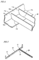
- FIG. 1 is a perspective view showing an insertion frame structure according to Example 1 not falling within the claims of the present invention.
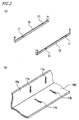
- FIG. 2 is a perspective view showing a primary member in the insertion frame structure of Example 1.
- FIG. 3 is a perspective view showing an auxiliary member in the insertion frame structure of Example 1.
- FIG. 4 is a perspective view showing a joint portion in the insertion frame structure of Example 1.
- FIG. 5 is a perspective view showing an assembly process of the primary member and the auxiliary member in the insertion frame structure of Example 1.
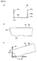
- FIG. 6 shows a left side view in FIG. 6(a) and a front view in FIG. 6(b) of a latch portion of the auxiliary member, and a sectional view in FIG. 6(c) showing the way of insertion into a latch hole of the primary member, in the insertion frame structure of Example 1.
- FIG. 7 shows a side view in FIG. 7(a) and a plan view in FIG. 7(b) of a latch portion of the primary member in the insertion frame structure of Example 1.
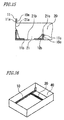
- FIG. 16 is a perspective view showing a housing using the insertion frame structure according to the present invention.
- a pair of primary members 10 having an L-shaped cross-section are placed being separated by a predetermined distance such that the inner surface sides of their L shapes face to each other symmetrically with respect to the center line passing the midpoint of the distance.
- auxiliary members 20 having a plate thickness t and an angular U-shaped cross-section are placed between the primary member 10 and the primary member 10. Then, the end portions of the auxiliary members 20 are joined with the primary members 10 by insertion from the inner surface sides of the L shapes of the primary members 10.
- the primary member 10 has a first latch portion 11 to be joined with the end portion of the auxiliary member 20 by insertion.
- a latch hole 11a as a through hole is formed on a wall 10a of the L shape of the first latch portion 11, and a latch hole 11b as a through hole is formed on a bottom portion 10b.
- the latch holes 11a and 11b in FIG. 2(b) each have a clearance (t + ⁇ ) sufficiently larger than the plate thickness t of the auxiliary member 20, and have, continuously from this clearance, a clearance smaller than the plate thickness t by a predetermined amount ( ⁇ ).
- the auxiliary member 20 has, at its end portion, a second latch portion 21 to be joined with the first latch portion 11 of the primary member 10.
- a convex portion 21a is formed at the end of a wall 20a where a bottom portion 20b is eliminated, and a convex portion 21b is formed at the bottom side of the wall 20a in the vicinity of the end of the wall 20a.
- the convex portions 21a and 21b of the auxiliary member 20 are respectively fitted into the latch holes 11a and 11b formed on the two surfaces (wall 10a and bottom portion 10b) of the primary member 10.
- the convex portions 21a and 21b of the auxiliary member 20 are pressed into the clearances smaller than the plate thickness t by the predetermined amount ( ⁇ ), of the latch holes 11a and 11b of the primary member 10.
- a contact avoiding portion is formed by obliquely cutting a lower portion of the convex portion 21a of the auxiliary member 20, such a situation that the auxiliary member 20 and the primary member 10 cannot be assembled because they contact each other upon assembly, can be avoided.
- the convex portions 21a and 21b of the auxiliary member 20 can be easily inserted into the clearances (t + ⁇ ) sufficiently larger than the plate thickness t of the auxiliary member 20, and next, by application of the principle of leverage, the convex portions 21a and 21b can be easily pressed and fitted into the clearances smaller than the plate thickness t by the predetermined amount ( ⁇ ).
- the latch holes 11a and 11b and the convex portions 21a and 21b are elastically deformed so that they are subjected to compression force from each other. Owing to the compression force, it becomes possible to prevent the convex portions 21a and 21b from easily coming off from the latch holes 11a and 11b when load is applied to the assembled insertion frame structure. Therefore, a rivet as shown in the conventional technique is not needed. In addition, since there is no looseness between the convex portions 21a and 21b and the latch holes 11a and 11b, the positioning accuracy between the primary member 10 and the auxiliary member 20 can be enhanced.
- the assembled insertion frame structure can be moved or carried by hand or the like.
- the inner side surface of the sheet metal housing 40 preferably contacts the side surface or the bottom surface of the primary member 10, the bottom surface of the auxiliary member 20, and the like, and therefore the insertion frame structure can be joined with the sheet metal housing 40 by resistance welding such as spot welding or seam welding, or the like.
- resistance welding such as spot welding or seam welding, or the like.
- Example 1 the case of using an L-shaped member as the primary member 10 has been described.
- the primary member 10 may be an angular U-shaped member having two L shapes.
- similar latch holes as in the case of using the member having one L shape may be formed on the bottom portion and one of the walls of the two L shapes of the angular U-shaped primary member 10.
- Example 1 the case where the cross-section of the auxiliary member 20 has an angular U shape, has been described.
- the present invention is not limited thereto.
- sheet metal or shape steel having an L shape may be used.
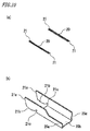
- FIG. 8 is a perspective view showing an insertion frame structure according to Embodiment 1 of the present invention.
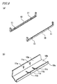
- FIG. 9 is a perspective view showing a primary member in the insertion frame structure of Embodiment 1.
- FIG. 10 is a perspective view showing an auxiliary member in the insertion frame structure of Embodiment 1.
- FIG. 11 is a perspective view showing a joint portion in the insertion frame structure of Embodiment 1.
- FIG. 12 is a perspective view showing an assembly process of the primary member and the auxiliary member in the insertion frame structure of Embodiment 1.
- FIG. 13 shows a left side view in FIG. 13(a) and a front view in FIG. 13(b) of a latch portion of the auxiliary member in the insertion frame structure of Embodiment 1.
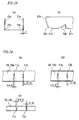
- FIG. 14 shows a left side view in FIG. 14(a) , a plan view in FIG. 14(b) , and a right side view in FIG. 14(c) of a latch portion of the primary member in the insertion frame structure of Embodiment 1.
- FIG. 15 is a sectional view of the latch portions of the primary member and the auxiliary member in the insertion frame structure of Embodiment 1.
- a pair of primary members 10 having an angular U-shaped cross-section are placed being separated by a predetermined distance and facing to each other symmetrically with respect to the center line passing the midpoint of the distance.
- auxiliary members 20 having an angular U-shaped cross-section are placed between the primary member 10 and the primary member 10. Then, the end portions of the auxiliary members 20 are joined with the primary members 10 by insertion from the inner surface sides of the angular U shapes of the primary members 10.
- the pair of primary members 10 having an angular U shape, that is, a groove shape are placed such that the groove faces upward, and the end portion of the auxiliary member 20 is joined with three surfaces of the primary member 10 by insertion.
- the primary member 10 has a first latch portion 11 to be joined with the end portions of the auxiliary member 20.
- the first latch portion 11 As shown in FIG. 9(b) , at the first latch portion 11, one of the walls rising from the bottom portion 10b of the primary member 10, which is closer to the center line side, that is, the inner side wall 10c is formed to be lower than the other wall 10a on the outer side.
- a latch hole 11a is formed on the outer side wall 10a
- a latch hole 11b is formed on the bottom portion 10b
- a latch hole 11c is formed on the inner side wall 10c.
- the latch hole 11 a, the latch hole 11b, and the latch hole 11c each have a clearance (t + ⁇ ) sufficiently larger than a plate thickness t of the auxiliary member 20, and have, continuously from this clearance, a clearance smaller than the plate thickness t by a predetermined amount ( ⁇ ).
- the auxiliary member 20 has, at its end portion, a second latch portion 21 to be joined with the first latch portion 11 of the primary member 10.
- a first convex portion 21a is formed at the end of a wall 20a of the auxiliary member 20, and a second convex portion 21b and a third convex portion 21c are formed at the bottom side of the wall 20a in the vicinity of the end of the wall 20a.
- the first convex portion 21a, the second convex portion 21b, and the third convex portion 21c of the auxiliary member 20 are respectively fitted into the latch holes 11a, 11b, and 11c formed on the three surfaces (outer side wall 10a, bottom portion 10b, and inner side wall 10c) of the primary member 10.
- the convex portions 21a, 21b, and 21c of the auxiliary member 20 are respectively inserted into the clearances (t + ⁇ ) larger than the plate thickness t of the auxiliary member 20, of the latch holes 11a, 11b, and 11c of the primary member 10.
- the convex portions 21a, 21b, and 21c of the auxiliary member 20 are pressed into the clearances smaller than the plate thickness t by the predetermined amount ( ⁇ ), of the latch holes 11a, 11b, and 11c of the primary member 10.
- the predetermined amount ( ⁇ ) of the latch holes 11a, 11b, and 11c of the primary member 10.
- contact avoiding portions 22a and 22b are formed by obliquely cutting a lower portion of the convex portion 21a and a front portion of the concave portion 21c of the auxiliary member 20, such a situation that the auxiliary member 20 and the primary member 10 cannot be assembled because they contact each other upon assembly, can be avoided.
- the positions and dimensions of the latch holes 11a, 11b, and 11c at the first latch portion 11 of the primary member 10, or the positions and dimensions of the convex portions 21a, 21b, and 21c at the second latch portion 21 of the auxiliary member 20, are determined so that the convex portions 21a, 21b, and 21c of the auxiliary member 20 will respectively contact the end surfaces of the latch holes 11a, 11b, and 11c of the primary member 10.
- the latch holes 11 a, 11b, and 11c are each formed by the clearance (t ⁇ ) sufficiently larger than the plate thickness t of the auxiliary member 20, and the clearance smaller than the plate thickness t by the predetermined amount ( ⁇ ) which is continuous from the clearance (t + ⁇ ).
- the convex portions 21 a, 21 b, and 21 c can be easily pressed into the clearance smaller than the plate thickness t by the predetermined amount ( ⁇ ).
- the latch holes 11a, 11b, and 11c and the convex portions 21a, 21b, and 21c are elastically deformed so that they are subjected to compression force from each other. Owing to the compression force, it becomes possible to prevent the convex portions 21a, 21b, and 21c from easily coming off from the latch holes 11a, 11b, and 11c when load is applied to the assembled insertion frame structure. In addition, the positioning accuracy between the primary member 10 and the auxiliary member 20 can be enhanced.
- the assembled insertion frame structure can be moved or carried by hand or the like.
- the convex portions 21a, 21b, and 21c of the auxiliary member 20 respectively contact the end surfaces of the latch holes 11a, 11b and 11c of the primary member 10. Therefore, when a heavy load is mounted on the auxiliary member 20, the load can be supported by three surfaces (the surfaces of the outer side wall 10a, the bottom portion 10b, and the inner side wall 10c) of the angular U shape of the primary member 10, and therefore the high stiffness of the angular U-shaped member can be effectively utilized.
- the inner side surface of the sheet metal housing 40 preferably contacts the side surface and the bottom surface of the primary member 10, the bottom surface of the auxiliary member 20, and the like, and therefore the assembled insertion frame structure can be joined with the sheet metal housing 40 by resistance welding such as spot welding or seam welding, or the like.
- resistance welding such as spot welding or seam welding, or the like.
- Embodiment 1 the case where the cross-section of the auxiliary member 20 has an angular U shape, has been described.
- the present invention is not limited thereto.
- sheet metal or shape steel having an L shape may be used.
- the latch holes 11a, 11b, and 11c of the first latch portion 11 of the primary member 10 each have a clearance (t + ⁇ ) larger than the plate thickness t of the auxiliary member 20, and have, continuously from this clearance, a clearance smaller than the plate thickness t of the auxiliary member 20.
- the latch holes 11a, 11b, and 11c of the first latch portion 11 of the primary member 10 each have a clearance (t + ⁇ ) larger than the plate thickness t of the auxiliary member 20, and have, continuously from this clearance, a clearance equal to the plate thickness t of the auxiliary member 20.
- the convex portions 21a, 21b, and 21c of the auxiliary member 20 can be easily pressed into the latch holes 11a, 11b, and 11c of the primary member 10 with a smaller force than in embodiment 1, and in addition, the members can be easily disassembled and then adjustment or the like can be easily performed.
- the auxiliary member 20 can be prevented from easily coming off from the primary member 10 when load is applied, so that a rivet as shown in the conventional technique is not needed.
- the positioning accuracy between the primary member 10 and the auxiliary member 20 can be enhanced.
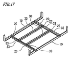
- FIG. 17 is a perspective view showing an insertion frame structure according to Embodiment 3 of the present invention.
- Embodiment 3 in the insertion frame structure composed of the primary member 10 and the auxiliary member 20 shown in embodiments 1 to 3, a plurality of second auxiliary members 30 joined with the auxiliary member 20 by insertion are provided.
- the auxiliary member 20 has a third latch portion 23, and the second auxiliary member 30 has a fourth latch portion 33.
- a latch hole is formed which has a clearance with a larger dimension than the plate thickness of the second auxiliary member 30, and has, continuously from this clearance, a clearance with a dimension equal to the plate thickness of the second auxiliary member 30 or smaller than the plate thickness of the second auxiliary member 30.
- the insertion frame structure further reinforced by the second auxiliary member 30 is obtained.
Landscapes
- Engineering & Computer Science (AREA)
- Architecture (AREA)
- Physics & Mathematics (AREA)
- Electromagnetism (AREA)
- Civil Engineering (AREA)
- Structural Engineering (AREA)
- General Engineering & Computer Science (AREA)
- Mechanical Engineering (AREA)
- Connection Of Plates (AREA)
- Joining Of Building Structures In Genera (AREA)
- Casings For Electric Apparatus (AREA)
Claims (5)
- Einsetzrahmenkonstruktion, die Folgendes aufweist:- ein Paar von rinnenförmigen Hauptelementen (10), deren Querschnittsformen zumindest teilweise winkelförmige U-Formen sind und die in einem vorbestimmten Abstand voneinander getrennt und symmetrisch zu einer Mittellinie, die durch den Mittelpunkt des vorbestimmten Abstands verläuft, einander zugewandt angeordnet sind;
und- eine Vielzahl von Hilfselementen (20), deren Querschnittsformen zumindest teilweise L-Formen sind und die zwischen den Hauptelementen (10) angeordnet sind,
wobei- die Hauptelemente (10) und die Hilfselemente (20) an ihren Verriegelungsbereichen (11, 21) miteinander verbunden sind,- die Hauptelemente (10) mit einem Bodenbereich (10b) der Rinnenform (10b) nach unten weisend angeordnet sind,- an einem Verriegelungsbereich von jedem der Hauptelemente (10) die Höhe von einer der Wände (10c), die sich näher bei der Mittellinienseite befindet, niedriger ist als die Höhe der anderen Wand (10a) auf der Außenseite,- an dem Verriegelungsbereich von jedem der Hauptelemente (10) Verriegelungsöffnungen (11a, 11b, 11c) mit einer Freiraumform in der einen Wand, dem Bodenbereich (10b) und der anderen Wand (10a) gebildet sind,- der Verriegelungsbereich von jedem Hilfselement (20) Folgendes aufweist:einen ersten konvexen Bereich (21a) zum Einsetzen in die Verriegelungsöffnung (11a), die in der anderen Wand (10a) gebildet ist;einen zweiten konvexen Bereich (21b) zum Einsetzen in die Verriegelungsöffnung (11b), die in dem Bodenbereich (10b) gebildet ist;und einen dritten konvexen Bereich (21c) zum Einsetzen in die Verriegelungsöffnung (11c), die in der einen Wand (10c) gebildet ist, und- jede der Verriegelungsöffnungen (11a, 11b, 11c) einen Freiraum mit einer größeren Abmessung als eine Plattendicke (t) des Hilfselements (20) aufweist sowie, ausgehend von dem Freiraum, in kontinuierlicher Weise einen Freiraum mit einer Abmessung gleich der Plattendicke (t) des Hilfselements (20) oder kleiner als die Plattendicke (t) des Hilfselements (20) aufweist. - Einsetzrahmenkonstruktion nach Anspruch 1,
wobei Kontakt vermeidende Bereiche durch schräges Schneiden eines unteren Bereichs des ersten konvexen Bereichs (21a) und der Seite des zweiten konvexen Bereich (21b) von dem dritten konvexen Bereich (21c) gebildet sind, so dass das Hilfselement (20) beim Einsetzen des ersten konvexen Bereichs (21a), des zweiten konvexen Bereichs (21b) und des dritten konvexen Bereichs (21c) in die jeweiligen Verriegelungsöffnungen (11a, 11b, 11c) nicht mit dem Hauptelement in Kontakt tritt. - Einsetzrahmenkonstruktion nach Anspruch 1 oder 2,
wobei die konvexen Bereiche (21a, 21b, 21c) derart ausgebildet sind, dass sie von den Verriegelungsöffnungen (11a, 11b, 11c) nicht nach außen hervorstehen. - Einsetzrahmenkonstruktion nach einem der Ansprüche 1 bis 3,
die ferner ein zweites Hilfselement (30) aufweist, das zumindest teilweise eine L-Form besitzt, wobei das zweite Hilfselement (30) zwischen den Hilfselementen (20) angeordnet ist,
wobei- die Hilfselemente (20) jeweils eine zweite Verriegelungsöffnung mit einem Freiraum mit einer größeren Abmessung als der Plattendicke des zweiten Hilfselements (30) aufweisen und, ausgehend von dem Freiraum, in kontinuierlicher Weise einen Freiraum mit einer Abmessung aufweisen, die gleich der Plattendicke des zweiten Hilfselements (30) oder kleiner als die Plattendicke des zweiten Hilfselement (30) ist, und- wobei das zweite Hilfselement (30) einen konvexen Bereich zum Einpassen in die zweite Verriegelungsöffnung aufweist. - Gehäuse, bei dem es sich um ein aus Metallblech gebildetes Metallblechgehäuse (40) handelt,
wobei eine Einsetzrahmenkonstruktion an der innenseitigen Oberfläche des Gehäuses (40) durch Schweißen befestigt ist,
wobei es sich bei der Einsetzrahmenkonstruktion um eine Einsetzrahmenkonstruktion nach einem der Ansprüche 1 bis 4 handelt.
Applications Claiming Priority (2)
| Application Number | Priority Date | Filing Date | Title |
|---|---|---|---|
| JP2011130820 | 2011-06-13 | ||
| EP12801130.1A EP2719479B1 (de) | 2011-06-13 | 2012-06-11 | Einführungsrahmenstruktur und gehäuse damit |
Related Parent Applications (2)
| Application Number | Title | Priority Date | Filing Date |
|---|---|---|---|
| EP12801130.1A Division-Into EP2719479B1 (de) | 2011-06-13 | 2012-06-11 | Einführungsrahmenstruktur und gehäuse damit |
| EP12801130.1A Division EP2719479B1 (de) | 2011-06-13 | 2012-06-11 | Einführungsrahmenstruktur und gehäuse damit |
Publications (2)
| Publication Number | Publication Date |
|---|---|
| EP2848330A1 EP2848330A1 (de) | 2015-03-18 |
| EP2848330B1 true EP2848330B1 (de) | 2016-07-27 |
Family
ID=47357074
Family Applications (2)
| Application Number | Title | Priority Date | Filing Date |
|---|---|---|---|
| EP12801130.1A Not-in-force EP2719479B1 (de) | 2011-06-13 | 2012-06-11 | Einführungsrahmenstruktur und gehäuse damit |
| EP14197309.9A Not-in-force EP2848330B1 (de) | 2011-06-13 | 2012-06-11 | Einführungsrahmenstruktur |
Family Applications Before (1)
| Application Number | Title | Priority Date | Filing Date |
|---|---|---|---|
| EP12801130.1A Not-in-force EP2719479B1 (de) | 2011-06-13 | 2012-06-11 | Einführungsrahmenstruktur und gehäuse damit |
Country Status (5)
| Country | Link |
|---|---|
| US (1) | US9624952B2 (de) |
| EP (2) | EP2719479B1 (de) |
| JP (1) | JP5558633B2 (de) |
| CN (1) | CN103608135B (de) |
| WO (1) | WO2012173087A1 (de) |
Families Citing this family (8)
| Publication number | Priority date | Publication date | Assignee | Title |
|---|---|---|---|---|
| DE112016002098B4 (de) | 2015-05-08 | 2019-06-19 | Mitsubishi Electric Corporation | Rahmenmontagekörper und Gehäuse |
| JP6576550B2 (ja) | 2016-05-11 | 2019-09-18 | 三菱電機株式会社 | フレーム及びフレームの組み立て方法 |
| TWI910033B (zh) | 2016-10-27 | 2025-12-21 | 美商艾德亞半導體科技有限責任公司 | 用於低溫接合的結構和方法 |
| US11056348B2 (en) | 2018-04-05 | 2021-07-06 | Invensas Bonding Technologies, Inc. | Bonding surfaces for microelectronics |
| US11387202B2 (en) | 2019-03-01 | 2022-07-12 | Invensas Llc | Nanowire bonding interconnect for fine-pitch microelectronics |
| ES2951679A1 (es) * | 2022-03-17 | 2023-10-24 | Pladur Gypsum S A U | Sistema de perfileria para una estructura de construccion y procedimiento de instalacion |
| JP7678355B2 (ja) * | 2022-11-16 | 2025-05-16 | テイ・エス テック株式会社 | 車両用シート |
| US20240229479A1 (en) * | 2023-01-10 | 2024-07-11 | Greg Hyde HRYNIEWICZ | Framing system including tubes joined with slots, hooks and wedges integrated into the tubes |
Family Cites Families (54)
| Publication number | Priority date | Publication date | Assignee | Title |
|---|---|---|---|---|
| US1214928A (en) * | 1911-11-15 | 1917-02-06 | Universal Electric Welding Co | Window sash or frame. |
| US3287874A (en) * | 1963-08-05 | 1966-11-29 | K S H Plastics Inc | Channel grid members with t-rail and hanger bracket |
| US3356402A (en) * | 1965-01-08 | 1967-12-05 | Wolverine Aluminum Corp | Framing system for a suspended ceiling |
| US3457688A (en) * | 1965-05-03 | 1969-07-29 | Eastern Prod Corp | Suspended ceiling |
| US3369332A (en) * | 1966-04-14 | 1968-02-20 | Walter Jim Corp | Ceiling suspension system |
| US3367695A (en) * | 1966-08-26 | 1968-02-06 | W J Haertel & Co | Ceiling suspension apparatus |
| US3979874A (en) * | 1972-11-24 | 1976-09-14 | Alabama Metal Industries Corporation | Suspended ceiling system and runner joints therefor |
| US4034534A (en) * | 1973-04-30 | 1977-07-12 | Intalite International | Louvered ceiling |
| US3921363A (en) * | 1974-05-17 | 1975-11-25 | Preston Metal & Roofing Prod | Cross member with end connector |
| US3996716A (en) * | 1976-09-15 | 1976-12-14 | Johns-Manville Corporation | Ceiling grid arrangement and connector used therewith |
| US4208851A (en) * | 1977-02-25 | 1980-06-24 | Roblin Industries, Inc. | Suspended ceiling system |
| US4264231A (en) * | 1980-03-04 | 1981-04-28 | Roper Corporation | Joint between main beam and cross beams in suspended ceiling system |
| US4389828A (en) * | 1980-06-12 | 1983-06-28 | Howmet Aluminum Corp. | Suspended ceiling system with crossing clip |
| JPS58106805U (ja) | 1982-01-14 | 1983-07-20 | 松下電工株式会社 | 照明器具用ル−バ |
| US4492066A (en) * | 1982-02-08 | 1985-01-08 | Donn Incorporated | Suspension ceiling grid system |
| US4494350A (en) * | 1982-09-20 | 1985-01-22 | Ceiling Dynamics, Inc. | Aluminum suspension system |
| US4598521A (en) * | 1984-09-05 | 1986-07-08 | Donn Incorporated | Suspension ceiling grid with end connector |
| GB8509345D0 (en) * | 1985-04-11 | 1985-05-15 | Hunter Douglas Ind Bv | Grid ceiling |
| US4757663A (en) * | 1987-05-11 | 1988-07-19 | Usg Interiors, Inc. | Drywall furring strip system |
| US4866900A (en) * | 1987-11-23 | 1989-09-19 | Chicago Metallic Corporation | Drywall furring system |
| US4844565A (en) * | 1988-01-11 | 1989-07-04 | Unisys Corporation | Quick-release spacer-latching-connector assembly |
| US5154031A (en) * | 1991-03-26 | 1992-10-13 | Schilling Components, Incorporated | Suspended ceiling system and connector clip therefor |
| US5137390A (en) * | 1992-01-16 | 1992-08-11 | E.H. Price Limited | Connection means for suspended ceiling grid |
| US5363622A (en) * | 1992-12-24 | 1994-11-15 | Armstrong World Industries, Inc. | Fire-rated drywall suspension system |
| CN2266621Y (zh) * | 1996-12-27 | 1997-11-05 | 李瑞荣 | 天花板轻钢架的改良结构 |
| US5966887A (en) * | 1997-09-10 | 1999-10-19 | Bailey Metal Products Limited | Suspended ceiling cross tee end connector |
| US6446406B1 (en) * | 2000-09-08 | 2002-09-10 | Worthington Armstrong Venture | Direct attached grid |
| US6651399B2 (en) * | 2001-11-27 | 2003-11-25 | Jui-Jung Li | Vertical intersecting lightweight steel frame |
| US6851238B2 (en) * | 2002-03-14 | 2005-02-08 | Robert J. Rebman | Ceiling grid system and method of assembling the same |
| JP4061943B2 (ja) | 2002-03-29 | 2008-03-19 | コクヨ株式会社 | 側部材の位置規制体 |
| US6729100B2 (en) * | 2002-04-30 | 2004-05-04 | Usg Interiors, Inc. | Main tee splice |
| SE524518E (sv) * | 2002-11-18 | 2007-11-27 | Caleidoscope Systems Ab | Funktionsinnertaksystem |
| US7490446B1 (en) * | 2003-12-31 | 2009-02-17 | Sen-Jung Chuang | Light steel ceiling rack |
| CN2676737Y (zh) * | 2004-02-27 | 2005-02-09 | 廖志中 | 多功能组合式框架结构 |
| LU91123B1 (en) | 2004-11-16 | 2006-05-17 | Uniflair Int Sa | Support structure for elevated floor assembly |
| US7690168B2 (en) * | 2005-07-29 | 2010-04-06 | Usg Interiors, Inc. | Wall mold attachment clip |
| US7634881B2 (en) * | 2005-10-31 | 2009-12-22 | Usg Interiors, Inc. | Cross panel |
| US7578107B2 (en) * | 2005-12-02 | 2009-08-25 | Worthington Armstrong Venture | Suspended ceiling segment |
| US20070283656A1 (en) * | 2006-06-12 | 2007-12-13 | Anderson Andy W | Fabric Wall Panel System and Track |
| JP5010215B2 (ja) * | 2006-09-07 | 2012-08-29 | アスリートFa株式会社 | 基板供給装置、基板巻取装置および基板処理システム |
| US7730690B2 (en) * | 2006-12-27 | 2010-06-08 | Usg Interiors, Inc. | Compression post assembly for wind up-lift of suspension soffits |
| US7392629B1 (en) * | 2006-12-28 | 2008-07-01 | Usg Interiors, Inc. | Suspended ceiling system |
| US7779593B2 (en) * | 2007-03-21 | 2010-08-24 | Chicago Metallic Corporation | Wall angle with pre-punched locating tabs |
| FR2915217B1 (fr) * | 2007-04-20 | 2009-07-10 | Imphy Alloys Sa | Structure pour le montage dans une paroi d'un batiment de batis destines a supporter des panneaux tels que des panneaux photovoltaiques |
| JP3135790U (ja) * | 2007-07-18 | 2007-09-27 | 株式会社新興産業 | 嵌合組合型構造部材 |
| JP3142241U (ja) | 2008-03-27 | 2008-06-05 | 株式会社新興産業 | 下側面嵌合組合型構造部材 |
| JP4927801B2 (ja) * | 2008-10-02 | 2012-05-09 | 有限会社 平野製作所 | ステー付き連結具 |
| CN201594955U (zh) * | 2009-04-30 | 2010-09-29 | 比亚迪股份有限公司 | 壳体装配结构以及采用该装配结构的壳体 |
| US8511028B2 (en) * | 2009-12-22 | 2013-08-20 | Usg Interiors, Llc | Clip connection |
| US8615948B2 (en) * | 2010-05-18 | 2013-12-31 | Usg Interiors, Llc | Seismic perimeter brace |
| US8359803B2 (en) * | 2011-05-17 | 2013-01-29 | Usg Interiors, Llc | Grid runner cap anchoring lance |
| US9109361B2 (en) * | 2011-10-26 | 2015-08-18 | Simpson Strong-Tie Company, Inc. | Bracing bridging member |
| US8955272B1 (en) * | 2013-07-30 | 2015-02-17 | Usg Interiors, Llc | Accessible stabilizer bar |
| US8955273B1 (en) * | 2013-08-06 | 2015-02-17 | Usg Interiors, Llc | Channel cross member |
-
2012
- 2012-06-11 CN CN201280028985.8A patent/CN103608135B/zh not_active Expired - Fee Related
- 2012-06-11 EP EP12801130.1A patent/EP2719479B1/de not_active Not-in-force
- 2012-06-11 WO PCT/JP2012/064902 patent/WO2012173087A1/ja not_active Ceased
- 2012-06-11 US US14/116,558 patent/US9624952B2/en active Active
- 2012-06-11 EP EP14197309.9A patent/EP2848330B1/de not_active Not-in-force
- 2012-06-11 JP JP2013520545A patent/JP5558633B2/ja not_active Expired - Fee Related
Also Published As
| Publication number | Publication date |
|---|---|
| US20140105674A1 (en) | 2014-04-17 |
| JP5558633B2 (ja) | 2014-07-23 |
| EP2719479B1 (de) | 2016-08-17 |
| EP2848330A1 (de) | 2015-03-18 |
| WO2012173087A1 (ja) | 2012-12-20 |
| JPWO2012173087A1 (ja) | 2015-02-23 |
| CN103608135A (zh) | 2014-02-26 |
| US9624952B2 (en) | 2017-04-18 |
| EP2719479A1 (de) | 2014-04-16 |
| EP2719479A4 (de) | 2015-03-18 |
| CN103608135B (zh) | 2016-10-19 |
Similar Documents
| Publication | Publication Date | Title |
|---|---|---|
| EP2719479B1 (de) | Einführungsrahmenstruktur und gehäuse damit | |
| JP6419321B2 (ja) | フレーム組立体および筐体 | |
| JP2015111569A (ja) | 打抜き加工及び曲げ加工された部品として製造されたコンタクト本体及び中実接触ピンを有するピンコンタクト | |
| US10840485B2 (en) | Composite end plate and battery module | |
| US9297594B2 (en) | Collector plate for a heat exchanger, and heat exchanger including such a plate | |
| JP2018075612A (ja) | 曲げ加工部材及びその製造方法 | |
| US9774155B2 (en) | Assembling structure of bus bar | |
| US20210313643A1 (en) | Battery module | |
| JP5912865B2 (ja) | 外壁板取付金具および外壁板取付構造 | |
| CN119726213A (zh) | 一种连接器的安装框架 | |
| CN106256059A (zh) | 盘装置用框体 | |
| JP6418596B2 (ja) | 太陽電池パネルの取付金具及び該取付金具による太陽電池パネルの取付構造 | |
| KR101503983B1 (ko) | 배터리모듈조립체의 하우징 구조 및 하우징 방법 | |
| JP5327913B2 (ja) | エレベータの乗りかご | |
| JP6460350B2 (ja) | ダクトおよびダクト接続構造 | |
| JP5838960B2 (ja) | 嵌め込みフレーム構造及びそれを用いた筐体 | |
| JP4848307B2 (ja) | 中空角材の組立固定構造 | |
| JP3135790U (ja) | 嵌合組合型構造部材 | |
| JP6377386B2 (ja) | 建具 | |
| JP3142241U (ja) | 下側面嵌合組合型構造部材 | |
| JP6610502B2 (ja) | ジャンクションボックスの製造方法 | |
| EP2463546A1 (de) | Metallische Energieführungskette | |
| JP2021082443A (ja) | 絶縁バリアの取付構造 | |
| JP6724355B2 (ja) | 配電盤の薄板パネルフレーム構造 | |
| JP5354150B2 (ja) | ドアストライカのリテーナ |
Legal Events
| Date | Code | Title | Description |
|---|---|---|---|
| PUAI | Public reference made under article 153(3) epc to a published international application that has entered the european phase |
Free format text: ORIGINAL CODE: 0009012 |
|
| 17P | Request for examination filed |
Effective date: 20141211 |
|
| AC | Divisional application: reference to earlier application |
Ref document number: 2719479 Country of ref document: EP Kind code of ref document: P |
|
| AK | Designated contracting states |
Kind code of ref document: A1 Designated state(s): AL AT BE BG CH CY CZ DE DK EE ES FI FR GB GR HR HU IE IS IT LI LT LU LV MC MK MT NL NO PL PT RO RS SE SI SK SM TR |
|
| R17P | Request for examination filed (corrected) |
Effective date: 20150914 |
|
| RBV | Designated contracting states (corrected) |
Designated state(s): AL AT BE BG CH CY CZ DE DK EE ES FI FR GB GR HR HU IE IS IT LI LT LU LV MC MK MT NL NO PL PT RO RS SE SI SK SM TR |
|
| GRAP | Despatch of communication of intention to grant a patent |
Free format text: ORIGINAL CODE: EPIDOSNIGR1 |
|
| RIC1 | Information provided on ipc code assigned before grant |
Ipc: E04B 9/12 20060101ALI20160115BHEP Ipc: F16B 21/09 20060101ALI20160115BHEP Ipc: F16B 7/20 20060101ALI20160115BHEP Ipc: E04B 9/34 20060101ALI20160115BHEP Ipc: E04B 2/76 20060101ALI20160115BHEP Ipc: E04B 1/58 20060101ALI20160115BHEP Ipc: F16B 5/10 20060101ALI20160115BHEP Ipc: B21D 47/00 20060101AFI20160115BHEP Ipc: E04B 9/04 20060101ALI20160115BHEP Ipc: F16B 7/04 20060101ALI20160115BHEP |
|
| INTG | Intention to grant announced |
Effective date: 20160203 |
|
| GRAS | Grant fee paid |
Free format text: ORIGINAL CODE: EPIDOSNIGR3 |
|
| GRAA | (expected) grant |
Free format text: ORIGINAL CODE: 0009210 |
|
| AC | Divisional application: reference to earlier application |
Ref document number: 2719479 Country of ref document: EP Kind code of ref document: P |
|
| AK | Designated contracting states |
Kind code of ref document: B1 Designated state(s): AL AT BE BG CH CY CZ DE DK EE ES FI FR GB GR HR HU IE IS IT LI LT LU LV MC MK MT NL NO PL PT RO RS SE SI SK SM TR |
|
| REG | Reference to a national code |
Ref country code: GB Ref legal event code: FG4D |
|
| REG | Reference to a national code |
Ref country code: CH Ref legal event code: EP |
|
| REG | Reference to a national code |
Ref country code: AT Ref legal event code: REF Ref document number: 815376 Country of ref document: AT Kind code of ref document: T Effective date: 20160815 |
|
| REG | Reference to a national code |
Ref country code: IE Ref legal event code: FG4D |
|
| REG | Reference to a national code |
Ref country code: DE Ref legal event code: R096 Ref document number: 602012021129 Country of ref document: DE |
|
| REG | Reference to a national code |
Ref country code: LT Ref legal event code: MG4D |
|
| REG | Reference to a national code |
Ref country code: NL Ref legal event code: MP Effective date: 20160727 |
|
| REG | Reference to a national code |
Ref country code: AT Ref legal event code: MK05 Ref document number: 815376 Country of ref document: AT Kind code of ref document: T Effective date: 20160727 |
|
| PG25 | Lapsed in a contracting state [announced via postgrant information from national office to epo] |
Ref country code: LT Free format text: LAPSE BECAUSE OF FAILURE TO SUBMIT A TRANSLATION OF THE DESCRIPTION OR TO PAY THE FEE WITHIN THE PRESCRIBED TIME-LIMIT Effective date: 20160727 Ref country code: IS Free format text: LAPSE BECAUSE OF FAILURE TO SUBMIT A TRANSLATION OF THE DESCRIPTION OR TO PAY THE FEE WITHIN THE PRESCRIBED TIME-LIMIT Effective date: 20161127 Ref country code: FI Free format text: LAPSE BECAUSE OF FAILURE TO SUBMIT A TRANSLATION OF THE DESCRIPTION OR TO PAY THE FEE WITHIN THE PRESCRIBED TIME-LIMIT Effective date: 20160727 Ref country code: NL Free format text: LAPSE BECAUSE OF FAILURE TO SUBMIT A TRANSLATION OF THE DESCRIPTION OR TO PAY THE FEE WITHIN THE PRESCRIBED TIME-LIMIT Effective date: 20160727 Ref country code: HR Free format text: LAPSE BECAUSE OF FAILURE TO SUBMIT A TRANSLATION OF THE DESCRIPTION OR TO PAY THE FEE WITHIN THE PRESCRIBED TIME-LIMIT Effective date: 20160727 Ref country code: NO Free format text: LAPSE BECAUSE OF FAILURE TO SUBMIT A TRANSLATION OF THE DESCRIPTION OR TO PAY THE FEE WITHIN THE PRESCRIBED TIME-LIMIT Effective date: 20161027 Ref country code: RS Free format text: LAPSE BECAUSE OF FAILURE TO SUBMIT A TRANSLATION OF THE DESCRIPTION OR TO PAY THE FEE WITHIN THE PRESCRIBED TIME-LIMIT Effective date: 20160727 |
|
| PG25 | Lapsed in a contracting state [announced via postgrant information from national office to epo] |
Ref country code: AT Free format text: LAPSE BECAUSE OF FAILURE TO SUBMIT A TRANSLATION OF THE DESCRIPTION OR TO PAY THE FEE WITHIN THE PRESCRIBED TIME-LIMIT Effective date: 20160727 Ref country code: BE Free format text: LAPSE BECAUSE OF FAILURE TO SUBMIT A TRANSLATION OF THE DESCRIPTION OR TO PAY THE FEE WITHIN THE PRESCRIBED TIME-LIMIT Effective date: 20160727 Ref country code: LV Free format text: LAPSE BECAUSE OF FAILURE TO SUBMIT A TRANSLATION OF THE DESCRIPTION OR TO PAY THE FEE WITHIN THE PRESCRIBED TIME-LIMIT Effective date: 20160727 Ref country code: GR Free format text: LAPSE BECAUSE OF FAILURE TO SUBMIT A TRANSLATION OF THE DESCRIPTION OR TO PAY THE FEE WITHIN THE PRESCRIBED TIME-LIMIT Effective date: 20161028 Ref country code: ES Free format text: LAPSE BECAUSE OF FAILURE TO SUBMIT A TRANSLATION OF THE DESCRIPTION OR TO PAY THE FEE WITHIN THE PRESCRIBED TIME-LIMIT Effective date: 20160727 Ref country code: SE Free format text: LAPSE BECAUSE OF FAILURE TO SUBMIT A TRANSLATION OF THE DESCRIPTION OR TO PAY THE FEE WITHIN THE PRESCRIBED TIME-LIMIT Effective date: 20160727 Ref country code: PT Free format text: LAPSE BECAUSE OF FAILURE TO SUBMIT A TRANSLATION OF THE DESCRIPTION OR TO PAY THE FEE WITHIN THE PRESCRIBED TIME-LIMIT Effective date: 20161128 Ref country code: PL Free format text: LAPSE BECAUSE OF FAILURE TO SUBMIT A TRANSLATION OF THE DESCRIPTION OR TO PAY THE FEE WITHIN THE PRESCRIBED TIME-LIMIT Effective date: 20160727 |
|
| PG25 | Lapsed in a contracting state [announced via postgrant information from national office to epo] |
Ref country code: EE Free format text: LAPSE BECAUSE OF FAILURE TO SUBMIT A TRANSLATION OF THE DESCRIPTION OR TO PAY THE FEE WITHIN THE PRESCRIBED TIME-LIMIT Effective date: 20160727 Ref country code: RO Free format text: LAPSE BECAUSE OF FAILURE TO SUBMIT A TRANSLATION OF THE DESCRIPTION OR TO PAY THE FEE WITHIN THE PRESCRIBED TIME-LIMIT Effective date: 20160727 |
|
| REG | Reference to a national code |
Ref country code: DE Ref legal event code: R097 Ref document number: 602012021129 Country of ref document: DE |
|
| REG | Reference to a national code |
Ref country code: FR Ref legal event code: PLFP Year of fee payment: 6 |
|
| PG25 | Lapsed in a contracting state [announced via postgrant information from national office to epo] |
Ref country code: CZ Free format text: LAPSE BECAUSE OF FAILURE TO SUBMIT A TRANSLATION OF THE DESCRIPTION OR TO PAY THE FEE WITHIN THE PRESCRIBED TIME-LIMIT Effective date: 20160727 Ref country code: DK Free format text: LAPSE BECAUSE OF FAILURE TO SUBMIT A TRANSLATION OF THE DESCRIPTION OR TO PAY THE FEE WITHIN THE PRESCRIBED TIME-LIMIT Effective date: 20160727 Ref country code: SK Free format text: LAPSE BECAUSE OF FAILURE TO SUBMIT A TRANSLATION OF THE DESCRIPTION OR TO PAY THE FEE WITHIN THE PRESCRIBED TIME-LIMIT Effective date: 20160727 Ref country code: BG Free format text: LAPSE BECAUSE OF FAILURE TO SUBMIT A TRANSLATION OF THE DESCRIPTION OR TO PAY THE FEE WITHIN THE PRESCRIBED TIME-LIMIT Effective date: 20161027 Ref country code: SM Free format text: LAPSE BECAUSE OF FAILURE TO SUBMIT A TRANSLATION OF THE DESCRIPTION OR TO PAY THE FEE WITHIN THE PRESCRIBED TIME-LIMIT Effective date: 20160727 |
|
| PLBE | No opposition filed within time limit |
Free format text: ORIGINAL CODE: 0009261 |
|
| STAA | Information on the status of an ep patent application or granted ep patent |
Free format text: STATUS: NO OPPOSITION FILED WITHIN TIME LIMIT |
|
| 26N | No opposition filed |
Effective date: 20170502 |
|
| PG25 | Lapsed in a contracting state [announced via postgrant information from national office to epo] |
Ref country code: SI Free format text: LAPSE BECAUSE OF FAILURE TO SUBMIT A TRANSLATION OF THE DESCRIPTION OR TO PAY THE FEE WITHIN THE PRESCRIBED TIME-LIMIT Effective date: 20160727 |
|
| PG25 | Lapsed in a contracting state [announced via postgrant information from national office to epo] |
Ref country code: MC Free format text: LAPSE BECAUSE OF FAILURE TO SUBMIT A TRANSLATION OF THE DESCRIPTION OR TO PAY THE FEE WITHIN THE PRESCRIBED TIME-LIMIT Effective date: 20160727 |
|
| REG | Reference to a national code |
Ref country code: CH Ref legal event code: PL |
|
| REG | Reference to a national code |
Ref country code: IE Ref legal event code: MM4A |
|
| PG25 | Lapsed in a contracting state [announced via postgrant information from national office to epo] |
Ref country code: IE Free format text: LAPSE BECAUSE OF NON-PAYMENT OF DUE FEES Effective date: 20170611 Ref country code: LU Free format text: LAPSE BECAUSE OF NON-PAYMENT OF DUE FEES Effective date: 20170611 Ref country code: LI Free format text: LAPSE BECAUSE OF NON-PAYMENT OF DUE FEES Effective date: 20170630 Ref country code: CH Free format text: LAPSE BECAUSE OF NON-PAYMENT OF DUE FEES Effective date: 20170630 |
|
| REG | Reference to a national code |
Ref country code: FR Ref legal event code: PLFP Year of fee payment: 7 |
|
| PG25 | Lapsed in a contracting state [announced via postgrant information from national office to epo] |
Ref country code: MT Free format text: LAPSE BECAUSE OF NON-PAYMENT OF DUE FEES Effective date: 20170611 |
|
| PG25 | Lapsed in a contracting state [announced via postgrant information from national office to epo] |
Ref country code: AL Free format text: LAPSE BECAUSE OF FAILURE TO SUBMIT A TRANSLATION OF THE DESCRIPTION OR TO PAY THE FEE WITHIN THE PRESCRIBED TIME-LIMIT Effective date: 20160727 |
|
| PG25 | Lapsed in a contracting state [announced via postgrant information from national office to epo] |
Ref country code: HU Free format text: LAPSE BECAUSE OF FAILURE TO SUBMIT A TRANSLATION OF THE DESCRIPTION OR TO PAY THE FEE WITHIN THE PRESCRIBED TIME-LIMIT; INVALID AB INITIO Effective date: 20120611 |
|
| PG25 | Lapsed in a contracting state [announced via postgrant information from national office to epo] |
Ref country code: CY Free format text: LAPSE BECAUSE OF FAILURE TO SUBMIT A TRANSLATION OF THE DESCRIPTION OR TO PAY THE FEE WITHIN THE PRESCRIBED TIME-LIMIT Effective date: 20160727 |
|
| PG25 | Lapsed in a contracting state [announced via postgrant information from national office to epo] |
Ref country code: MK Free format text: LAPSE BECAUSE OF FAILURE TO SUBMIT A TRANSLATION OF THE DESCRIPTION OR TO PAY THE FEE WITHIN THE PRESCRIBED TIME-LIMIT Effective date: 20160727 |
|
| PG25 | Lapsed in a contracting state [announced via postgrant information from national office to epo] |
Ref country code: TR Free format text: LAPSE BECAUSE OF FAILURE TO SUBMIT A TRANSLATION OF THE DESCRIPTION OR TO PAY THE FEE WITHIN THE PRESCRIBED TIME-LIMIT Effective date: 20160727 |
|
| REG | Reference to a national code |
Ref country code: GB Ref legal event code: 746 Effective date: 20200810 |
|
| REG | Reference to a national code |
Ref country code: DE Ref legal event code: R084 Ref document number: 602012021129 Country of ref document: DE |
|
| P01 | Opt-out of the competence of the unified patent court (upc) registered |
Effective date: 20230512 |
|
| PGFP | Annual fee paid to national office [announced via postgrant information from national office to epo] |
Ref country code: GB Payment date: 20240502 Year of fee payment: 13 |
|
| PGFP | Annual fee paid to national office [announced via postgrant information from national office to epo] |
Ref country code: DE Payment date: 20240502 Year of fee payment: 13 |
|
| PGFP | Annual fee paid to national office [announced via postgrant information from national office to epo] |
Ref country code: IT Payment date: 20240513 Year of fee payment: 13 Ref country code: FR Payment date: 20240509 Year of fee payment: 13 |
|
| REG | Reference to a national code |
Ref country code: DE Ref legal event code: R119 Ref document number: 602012021129 Country of ref document: DE |
|
| GBPC | Gb: european patent ceased through non-payment of renewal fee |
Effective date: 20250611 |
|
| PG25 | Lapsed in a contracting state [announced via postgrant information from national office to epo] |
Ref country code: GB Free format text: LAPSE BECAUSE OF NON-PAYMENT OF DUE FEES Effective date: 20250611 |
|
| PG25 | Lapsed in a contracting state [announced via postgrant information from national office to epo] |
Ref country code: DE Free format text: LAPSE BECAUSE OF NON-PAYMENT OF DUE FEES Effective date: 20260101 |
|
| PG25 | Lapsed in a contracting state [announced via postgrant information from national office to epo] |
Ref country code: IT Free format text: LAPSE BECAUSE OF NON-PAYMENT OF DUE FEES Effective date: 20250611 |
|
| PG25 | Lapsed in a contracting state [announced via postgrant information from national office to epo] |
Ref country code: FR Free format text: LAPSE BECAUSE OF NON-PAYMENT OF DUE FEES Effective date: 20250630 |