EP2848337B1 - Agencement de mâchoire de serrage - Google Patents
Agencement de mâchoire de serrage Download PDFInfo
- Publication number
- EP2848337B1 EP2848337B1 EP14184297.1A EP14184297A EP2848337B1 EP 2848337 B1 EP2848337 B1 EP 2848337B1 EP 14184297 A EP14184297 A EP 14184297A EP 2848337 B1 EP2848337 B1 EP 2848337B1
- Authority
- EP
- European Patent Office
- Prior art keywords
- jaw
- carrier
- extension
- exchangeable
- contact
- Prior art date
- Legal status (The legal status is an assumption and is not a legal conclusion. Google has not performed a legal analysis and makes no representation as to the accuracy of the status listed.)
- Active
Links
Images


Classifications
-
- B—PERFORMING OPERATIONS; TRANSPORTING
- B25—HAND TOOLS; PORTABLE POWER-DRIVEN TOOLS; MANIPULATORS
- B25B—TOOLS OR BENCH DEVICES NOT OTHERWISE PROVIDED FOR, FOR FASTENING, CONNECTING, DISENGAGING, OR HOLDING
- B25B5/00—Clamps
- B25B5/06—Arrangements for positively actuating jaws
- B25B5/10—Arrangements for positively actuating jaws using screws
-
- B—PERFORMING OPERATIONS; TRANSPORTING
- B23—MACHINE TOOLS; METAL-WORKING NOT OTHERWISE PROVIDED FOR
- B23B—TURNING; BORING
- B23B31/00—Chucks; Expansion mandrels; Adaptations thereof for remote control
- B23B31/02—Chucks
- B23B31/10—Chucks characterised by the retaining or gripping devices or their immediate operating means
- B23B31/12—Chucks with simultaneously-acting jaws, whether or not also individually adjustable
- B23B31/16—Chucks with simultaneously-acting jaws, whether or not also individually adjustable moving radially
- B23B31/1627—Details of the jaws
- B23B31/16279—Fixation on the master jaw
-
- B—PERFORMING OPERATIONS; TRANSPORTING
- B25—HAND TOOLS; PORTABLE POWER-DRIVEN TOOLS; MANIPULATORS
- B25B—TOOLS OR BENCH DEVICES NOT OTHERWISE PROVIDED FOR, FOR FASTENING, CONNECTING, DISENGAGING, OR HOLDING
- B25B1/00—Vices
- B25B1/24—Details, e.g. jaws of special shape, slideways
- B25B1/2405—Construction of the jaws
-
- B—PERFORMING OPERATIONS; TRANSPORTING
- B25—HAND TOOLS; PORTABLE POWER-DRIVEN TOOLS; MANIPULATORS
- B25B—TOOLS OR BENCH DEVICES NOT OTHERWISE PROVIDED FOR, FOR FASTENING, CONNECTING, DISENGAGING, OR HOLDING
- B25B5/00—Clamps
- B25B5/06—Arrangements for positively actuating jaws
- B25B5/08—Arrangements for positively actuating jaws using cams
Definitions
- the present invention relates to a clamping jaw arrangement with a support jaw which defines a support surface on its upper side and has at its rear end region over the support surface upwardly projecting extension, and a removable jaw, which is interchangeably plugged onto the extension of the support jaw or can be plugged, wherein on the back of the interchangeable jaw two retaining cheeks are provided, which engage around the extension of the support jaw laterally, and on the extension of the support jaw and on the inner sides of the retaining cheeks connecting webs and connecting grooves which enclose a predetermined identical angle ⁇ ⁇ 90 ° with the support surface and positively with each other come into engagement when the interchangeable jaw is inserted from above on the extension of the support jaw, are formed, and wherein at the front end face of the extension of the support jaw and the rear end face of the interchangeable jaw corresponding percussionfläc hen are provided which come into contact with each other when the interchangeable jaw is placed on the support jaw, and with the support surface of the support jaw a predetermined identical angle ⁇ ⁇ 90 ° include,
- the present invention relates to clamping jaw assemblies, wherein the connecting webs and connecting grooves under a predetermined identical angle ⁇ ⁇ 90 ° relative to the support surface are inclined and / or in which the securing means are designed in the form of a locking screw which is screwed into an open towards the top of the extension of the support threaded bore of the extension, wherein the interchangeable jaw has a contact surface, with which the locking screw when screwing into the support jaw comes into contact to secure the interchangeable jaw on the support jaw against peeling.
- clamping jaws are used on gripper fingers of gripper arrangements in order to grasp (tension) components for transport.
- machine tools such as lathes and milling machines
- chucks which are designed as three-jaw chuck. These have a dimensionally stable chuck body, which has a central receptacle for a workpiece to be clamped, and three clamping jaws, which are arranged in radial jaw guides of the chuck body and can be moved jointly by actuating an actuator radially inwardly or outwardly.
- the jaws may be integrally formed.
- jaw assemblies used each having a base or support jaw, which is held in the chuck body, and a change or top jaw, which protrudes from the chuck body and is connected to the support jaw having.
- corresponding contact surfaces are provided on the front end surface of the extension of the support jaw and a rear end face of the interchangeable jaw, which come into contact with each other when the interchangeable jaw is placed on the support jaw.
- securing means are provided to prevent removal of the interchangeable jaw from the support jaw.
- the securing means here comprise a securing element, which is held displaceably in a bore of the extension of the support jaw, and by a compression spring in a recess which is formed in the rear abutment surface of the interchangeable jaw, is pressed.
- the inner surfaces of the retaining cheeks and the lateral outer surfaces of the extension have in the area the connecting webs and connecting grooves in cross-section an arcuate or curved contour.
- the inner surfaces of the retaining cheeks and the outer surfaces of the extension in the region of the connecting webs and / or the connecting grooves over its entire length or at least over a large length of length may be arcuate or curved.
- the transitions are continuous, ie without edge formation.
- the arcuate regions should make up at least 75, in particular at least 85 and preferably at least 95% of the length of the contour.
- connection areas between the extension and the interchangeable jaw are low in contamination, whereby a high precision is achieved. Furthermore, the occurrence of stress due to notch effects is reduced.
- the arrangement is preferably made such that the inner surfaces of the retaining cheeks and the lateral outer surfaces of the extension are formed in a complementary manner in such a way that the connecting webs / connecting grooves come into contact at least substantially flat.
- the connecting webs and / or connecting grooves can form a wave-like contour.
- retaining cheeks on their inner sides in each case a wave-like contour with a corrugation-like portion which forms a connecting groove for receiving a connecting web of the support jaw and an adjoining wave-like portion which forms a connecting web which at the back of the connecting web of the support jaw in investment, own.
- the angle ⁇ at which the connecting webs and connecting grooves are inclined with respect to the supporting surface smaller than the angle ⁇ , which include the contact surfaces with the support surface.
- the angle at which the connecting webs and connecting grooves are inclined relative to the bearing surface preferably by at least 0.1 °, in particular at least 0.3 ° and preferably at least 0.5 ° and / or at most 8 °, in particular at most 6 ° and preferably at most 5 °, smaller than the angle ⁇ , which include the contact surfaces with the support surface.
- the securing means are preferably designed and / or positioned such that they exert on the interchangeable jaw a pressure force directed in the direction of the bearing surface of the extension of the carrier jaw. This embodiment is based on the consideration of exerting a compressive force on the interchangeable jaw on the securing means so that it is pressed reliably against the contact surfaces of the support jaw.
- the securing means comprise a locking screw which is screwed into an open towards the top of the extension of the support jaw threaded bore of the extension, wherein the interchangeable jaw having a contact surface with which the locking screw when screwing into the support jaw comes into contact with the To secure the jaw to the support jaw against peeling, and that the threaded hole with the support surface forms an angle ⁇ ⁇ 90 °, so that the interchangeable jaw is pressed in the direction of the contact surface of the extension of the support jaw during insertion of the locking screw.
- the contact surfaces at the front end face of the extension and the rear end face of the interchangeable jaw with the support surface can enclose an angle of 90 °.
- the contact surfaces are inclined at a predetermined identical angle ⁇ 90 ° relative to the support surface.
- the angle ⁇ which encloses the threaded bore with the support surface, is equal to or smaller than the angle ⁇ , under which the connecting webs and connecting grooves are inclined relative to the support surface, and / or as the angle y , under which the contact surfaces are inclined relative to the support surface.
- the inclination angle of the connecting webs and connecting grooves, the threaded bore and the contact surfaces are the same size.
- a recess for receiving the head of the locking screw is formed, wherein the bottom of the recess is in particular in a direction perpendicular to the axis of the threaded bore plane.
- the interchangeable jaw having on its upper side a recess at the bottom of the contact surface is formed, which may also lie in a plane perpendicular to the axis of the threaded bore plane.
- elastic clamping means are provided on the support jaw which exert a compressive force on the interchangeable jaw, by which the contact surface of the interchangeable jaw is pressed in the direction of the contact surface of the extension of the support jaw, when the interchangeable jaw on the support jaw is plugged.
- the elastic tensioning means have compression spring elements, which are held in corresponding receptacles in the extension of the support jaw and are in contact with connecting webs of the interchangeable jaw, when the interchangeable jaw is placed on the support jaw to one of the contact surface of the support jaw to exert away directed compressive force on the connecting webs.
- a compressive force is exerted on the interchangeable jaw by the elastic clamping means and in particular the compression spring elements, through which the interchangeable jaw is pressed against the contact surface of the support jaw.
- the elastic clamping means are preferably designed or arranged so that the pressure force is exerted on the interchangeable jaw in the lower region.
- the interchangeable jaw overlaps the carrier jaw in the plugged-on state such that two holding webs come into abutment on opposite side surfaces of the carrier jaw in order to position the interchangeable jaw on the carrier jaw.
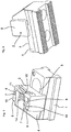
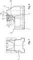
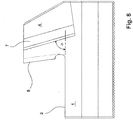
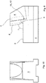
- FIGS. 1 to 7 a first embodiment of a jaw assembly according to the present invention is shown, which is particularly intended for use in conventional three-jaw chucks and gripper devices, but can also be used in other clamping or gripping device.
- the jaw assembly comprises a support jaw 1, which is used in a chuck inserted into a radial guide groove of the chuck body and movably guided therein in its longitudinal direction, and a removable jaw 2, which protrudes from the chuck body and is secured to the upper side of the support jaw 1.
- the support jaw 1 defines on its upper side a support surface 3, on which the interchangeable jaw 2 comes to rest.
- the support jaw 1 has at its rear end region on the support surface 3 upwardly projecting extension 4, which forms a contact surface 5 on its front end face on which a corresponding contact surface 6 comes to rest on the rear end face of the jaw 2, when the interchangeable jaw 2 is fixed to the support jaw 1.
- the contact surfaces 5, 6 are inclined at an identical angle ⁇ of 85 ° relative to the support surface 3 of the support jaw 1.
- the interchangeable jaw 2 At the two opposite side surfaces of the extension 4 connecting webs 7 are formed, on which the interchangeable jaw 2 is attached from above.
- the interchangeable jaw 2 on its rear side retaining cheeks 8, which surround the extension 4 side and on which on the inside in each case one to the connecting web 7 on the corresponding side surface of the support jaw 1 corresponding connecting groove 9 and an adjoining connecting web 10 are formed.
- the connecting grooves 9 and connecting webs 10 are compared to the support surface 3 of the support jaw 1 at an angle ⁇ , which is here about 85 °, inclined.
- ⁇ which is here about 85 °, inclined.
- the inner contour of the retaining cheeks 8 of the interchangeable jaw 2 in the region of the connecting grooves 9 and connecting webs 10 are formed wave-like curved.
- the curved connecting webs 7 are formed on the outer side walls of the extension 4 of the support jaw 1, so that the connecting webs 7, 10 on the support jaw 1 on the one hand and the change jaw 2 on the other hand in their contact area surface come into contact. Due to the continuous transitions, dirt accumulation can be avoided.
- a locking screw 11 is provided to secure the interchangeable jaw 2 on the support jaw 1. This is screwed into a threaded bore 12, which is formed in the extension 4 of the support jaw 1 and opens into the top.
- the threaded bore 12 is inclined relative to the bearing surface 3 and closes with this an angle ⁇ , which in turn is 85 °, so that the inclination angle ⁇ ⁇ ⁇ the connecting webs / connecting grooves 7, 9, 10, the contact surfaces 5, 6 and the threaded hole 12 is the same size.
- the threaded bore 12 is positioned such that the head 11a of the locking screw 11 comes into contact with a corresponding contact surface 13 of the interchangeable jaw 2 when screwed into the carrier jaw 1, so that the interchangeable jaw 2 is depressed on the one hand in the direction of the bearing surface 3 of the carrier jaw 1 and also against the contact surface 5 of the support jaw 1 is pressed.
- a recess 14 for receiving the head 11a of the locking screw 11 is formed in the extension 4 of the support jaw 1, wherein the bottom of the recess 14 is located in a plane perpendicular to the axis of the threaded bore 12 level.
- the change jaw 2 has a top on its top corresponding recess 15, the bottom of which defines the contact surface 13 which lies in a plane perpendicular to the axis of the threaded bore plane.
- FIG. 8 a carrier jaw 1 of another jaw assembly according to the present invention is shown.
- This defines on its upper side a bearing surface 3 for a change jaw 2, not shown, and has at its rear end portion on the support surface 3 upwardly projecting extension 4.
- a contact surface 5 is formed at the front end face of the extension 4.
- FIG. 8 recognizable that on the outer side surfaces of the extension 4 in each case an outwardly projecting connecting web 7 is provided.
- the support jaw 1 corresponds to the FIG. 8 the carrier jaw 1 from the previously described first embodiment of a clamping jaw arrangement according to the invention.
- the angle ⁇ under which the connecting webs 7 and thus the connecting grooves of the corresponding interchangeable jaw 2 are inclined relative to the support surface 3, shallower than the inclination angle ⁇ , which the contact surface 5 of the support jaw 1 and thus also the contact surface of the interchangeable jaw 2 with the support surface 3 include.
- the angle difference is exaggerated here and is about 1 to 2 °. The difference in angle causes the interchangeable jaw 2 is pulled against the contact surface 5 of the support jaw 1 when the interchangeable jaw 2 pushed onto the extension 4 of the support jaw 1 and the positive connection between the connecting webs 7 of the support jaw 1 and the connecting webs 10 / connecting grooves 9 of the interchangeable jaw 2 is produced.
- FIGS. 9 to 11 the support jaw 1 of a third embodiment of a clamping jaw arrangement according to the invention is shown.
- This has the same structure as the support jaw 1 in the FIGS. 1 to 7 described first embodiment of an inventive The jaw assembly.
- here are the connecting webs 7 on the upwardly projecting extension 4 of the support jaw 1 at the same angle ⁇ relative to the support surface 3 of the support jaw 1 inclined as the contact surface 5, which is formed on the front end face of the extension 4.
- elastic clamping means are provided on the support jaw 1, which exert on the interchangeable jaw 2 a compressive force by which the contact surface 6 of the interchangeable jaw 2 in the direction of the contact surface 5 of the extension 4 of the support jaw 1 is pressed when the interchangeable jaw 2 on the Carrier jaw 1 is inserted.
- the elastic clamping means are here in the form of compression spring elements 16 which are held in corresponding receptacles - here mounting holes 17 - in the extension 4 of the support jaw 1 and are in contact with the connecting webs 10 of the interchangeable jaw 2, when the interchangeable jaw 2 on the support jaw 1 is inserted to exert a directed from the contact surface 5 of the support jaw 1 pressure force F on the connecting webs.
- the compression spring elements 16 are positioned in a lower region of the extension 4 and here even below the support surface 3, so that the force exerted by the compression spring elements 16 compressive forces F are introduced into the lower region of the interchangeable jaw 2. In this way, it is ensured that the abutment surface 6 of the interchangeable jaw 2 rests flat against the abutment surface 5 of the carrier jaw 1 and in close contact therewith.
Landscapes
- Engineering & Computer Science (AREA)
- Mechanical Engineering (AREA)
- Clamps And Clips (AREA)
Claims (14)
- Dispositif de mâchoire de serrage avec une mâchoire porteuse (1), qui définit une surface d'appui (3) sur sa face supérieure et présente une extension (4) dépassant vers le haut de la surface d'appui (3) dans sa zone d'extrémité arrière, et une mâchoire interchangeable (2), qui est fixée de manière interchangeable ou peut être fixée à l'extension (4) de la mâchoire porteuse (1), deux joues de retenue (8) étant prévues sur la face arrière de la mâchoire interchangeable (2), qui entourent latéralement l'extension (4) de la mâchoire porteuse (1), et des nervures de connexion (7, 10) et des rainures de connexion (9) étant formées sur l'extension (4) de la mâchoire porteuse (1) et sur les côtés intérieurs des joues de retenue (8), qui entourent un angle identique prédéterminé (α) ≤ 90° avec la surface d'appui (3) et s'engagent positivement l'un dans l'autre lorsque la mâchoire interchangeable (2) est insérée par le haut sur l'extension (4) de la mâchoire porteuse (1), et des surfaces de contact correspondantes (5, 6) étant prévues sur la face d'extrémité avant de l'extension (4) de la mâchoire porteuse (1) et la face d'extrémité arrière de la mâchoire d'échange (2), lesquelles surfaces de contact viennent en contact l'une avec l'autre lorsque la mâchoire interchangeable (2) est insérée sur la mâchoire porteuse (1), et qui enferment un angle identique prédéterminé (γ) ≤ 90° avec la surface d'appui (3) de la mâchoire porteuse (1), et avec des moyens de fixation (11) pour fixer la mâchoire interchangeable (2) sur la mâchoire porteuse (1) contre le décollement, caractérisé en ce que les surfaces intérieures des joues de retenue (8) et les surfaces extérieures latérales de l'extension (4) dans la zone des nervures de connexion (7, 10) et des rainures de connexion (9) ont un contour arqué ou courbé en section transversale.
- Dispositif de mâchoire de serrage selon la revendication 1, caractérisé en ce que les surfaces intérieures des joues de retenue (8) et les surfaces extérieures de l'extension (4) dans la zone des nervures de connexion (7, 10) et/ou des rainures de connexion (9) sont gablées ou courbées sur toute leur longueur ou au moins sur une grande partie de leur longueur.
- Dispositif de mâchoire de serrage selon la revendication 1 ou 2, caractérisé en ce que les nervures de connexion (7, 10) et/ou les rainures de connexion (9) forment un contour ondulé.
- Dispositif de mâchoire de serrage selon l'une des revendications précédentes, caractérisé en ce que les joues de retenue (8) présentent chacune sur leurs côtés intérieurs un contour en forme d'onde avec une partie en forme de dépression d'onde qui forme une rainure de connexion (9) pour recevoir une nervure de connexion (7) de la mâchoire porteuse (1) et avec une partie en forme de crête d'onde qui est adjacente à cette dernière et forme une nervure de connexion (10) qui vient en contact avec le côté arrière de la rainure de connexion (7) de la mâchoire porteuse (1).
- Dispositif de mâchoire de serrage avec une mâchoire porteuse (1), qui définit une surface d'appui (3) sur sa face supérieure et présente une extension (4) dépassant vers le haut de la surface d'appui (3) dans sa zone d'extrémité arrière, et une mâchoire interchangeable (2), qui est fixée de manière interchangeable ou peut être fixée à l'extension (4) de la mâchoire porteuse (1), deux joues de retenue (8) étant prévues sur la face arrière de la mâchoire interchangeable (2), qui entourent latéralement l'extension (4) de la mâchoire porteuse (1), et des nervures de connexion (7, 10) et des rainures de connexion (9) étant formées sur l'extension (4) de la mâchoire porteuse (1) et sur les côtés intérieurs des joues de retenue (8), qui entourent un angle identique prédéterminé (α) ≤ 90° avec la surface d'appui (3) et s'engagent positivement l'un dans l'autre lorsque la mâchoire interchangeable (2) est insérée par le haut sur l'extension (4) de la mâchoire porteuse (1), et des surfaces de contact correspondantes (5, 6) étant prévues sur une face d'extrémité avant de l'extension (4) de la mâchoire porteuse (1) et une face d'extrémité arrière de la mâchoire d'échange (2), lesquelles surfaces de contact viennent en contact l'une avec l'autre lorsque la mâchoire interchangeable (2) est insérée sur la mâchoire porteuse (1), et qui enferment un angle identique prédéterminé (γ) ≤ 90° avec la surface de contact (3) de la mâchoire porteuse (1), et des moyens de fixation (11) pour fixer la mâchoire interchangeable (2) sur la mâchoire porteuse (1) contre le décollement, caractérisé en ce que l'angle (α) sous lequel les nervures de liaison (7, 10) et les rainures de liaison (9) sont inclinées par rapport à la surface d'appui (3) est plus petit que l'angle (γ) que les surfaces de contact (5, 6) entourent avec la surface d'appui (3).
- Dispositif de mâchoire de serrage selon la revendication 5, caractérisé en ce que l'angle (α) sous lequel les nervures de liaison (7, 10) et les rainures de liaison (9) sont inclinées par rapport à la surface d'appui (3) est plus petit que l'angle (γ) que les surfaces de contact (5, 6) entourent la surface d'appui (3) d'au moins 0,1°, en particulier au moins 0,3° et de préférence au moins 0,5° et/ou maximum 8°, en particulier maximum 6° et de préférence maximum 5°.
- Dispositif de mâchoire de serrage selon l'une des revendications précédentes, caractérisé en ce que les moyens de verrouillage comportent une vis de verrouillage (11) qui peut être vissée dans un alésage fileté (12) de l'extension (4) ouvert vers le côté supérieur de l'extension (4) de la mâchoire porteuse (1), la mâchoire interchangeable (2) présentant une surface de contact (13) avec laquelle la vis de verrouillage (11) vient en contact lorsqu'elle est vissée dans la mâchoire porteuse (1) afin de fixer la mâchoire d'échange (2) sur la mâchoire porteuse (1) pour l'empêcher d'être retirée.
- Dispositif de mâchoire de serrage selon la revendication 7, caractérisé en ce que l'alésage fileté (12) forme un angle (β) ≤ 90° avec la surface d'appui (3) de sorte que la mâchoire interchangeable (2) est pressée dans la direction de la surface de contact (5) de l'extension (4) de la mâchoire porteuse (1) lorsque la vis de verrouillage (11) est vissée.
- Dispositif de mâchoire de serrage selon la revendication 7 ou 8, caractérisé en ce qu'un évidement (14) destiné à recevoir la tête (11a) de la vis de verrouillage (11) est formé dans l'extension (4) de la mâchoire porteuse (1), le fond de l'évidement (14) se trouvant en particulier dans un plan perpendiculaire à l'axe de l'alésage fileté (12).
- Dispositif de mâchoire de serrage selon l'une des revendications 7 à 9, caractérisé en ce que la mâchoire interchangeable (2) présente sur sa face supérieure un évidement (15), sur sa face supérieure, sur le fond duquel est formée la surface de contact (13).
- Dispositif de mâchoire de serrage selon l'une des revendications précédentes, caractérisé en ce que des moyens de serrage élastiques sont prévus sur la mâchoire porteuse (1), qui exercent une force de compression sur la mâchoire interchangeable (2), au moyen de laquelle la surface de contact (6) de la mâchoire interchangeable (2) est pressée dans la direction de la surface de contact (5) de l'extension (4) de la mâchoire porteuse (1) lorsque la mâchoire interchangeable (2) est insérée sur la mâchoire porteuse (1).
- Dispositif de mâchoire de serrage selon la revendication 11, caractérisé en ce que les moyens de serrage élastiques comprennent des éléments de ressort de compression (16) qui sont maintenus dans des réceptacles correspondants (17) dans l'extension (4) de la mâchoire porteuse (1) et sont en contact avec une nervure de connexion (10) de la mâchoire interchangeable (2) lorsque la mâchoire interchangeable (2) est insérée sur la mâchoire porteuse (1) afin d'exercer une force de compression dirigée à l'opposé de la surface de contact (5) de la mâchoire porteuse (1) sur les nervures de connexion (10).
- Dispositif de mâchoire de serrage selon la revendication 12, caractérisé en ce que les moyens de serrage élastiques (16) sont positionnés en particulier de telle sorte qu'ils exercent la force de compression sur une zone inférieure de la mâchoire interchangeable (2) lorsque la mâchoire interchangeable (2) est insérée sur la mâchoire porteuse (1).
- Dispositif de mâchoire de serrage selon l'une des revendications précédentes, caractérisé en ce que la mâchoire interchangeable (2) s'engage sur la mâchoire porteuse (1) à l'état inséré de telle sorte que deux bandes de retenue viennent en contact avec des surfaces latérales opposées de la mâchoire porteuse (1) afin de positionner la mâchoire interchangeable sur la mâchoire porteuse (1).
Applications Claiming Priority (1)
| Application Number | Priority Date | Filing Date | Title |
|---|---|---|---|
| DE202013104141.6U DE202013104141U1 (de) | 2013-09-11 | 2013-09-11 | Spannbackenanordnung |
Publications (2)
| Publication Number | Publication Date |
|---|---|
| EP2848337A1 EP2848337A1 (fr) | 2015-03-18 |
| EP2848337B1 true EP2848337B1 (fr) | 2018-08-08 |
Family
ID=51584934
Family Applications (1)
| Application Number | Title | Priority Date | Filing Date |
|---|---|---|---|
| EP14184297.1A Active EP2848337B1 (fr) | 2013-09-11 | 2014-09-10 | Agencement de mâchoire de serrage |
Country Status (2)
| Country | Link |
|---|---|
| EP (1) | EP2848337B1 (fr) |
| DE (1) | DE202013104141U1 (fr) |
Families Citing this family (7)
| Publication number | Priority date | Publication date | Assignee | Title |
|---|---|---|---|---|
| DE102015109026A1 (de) * | 2015-06-08 | 2016-12-08 | Ahmet Teoman Atil | Spannsystem zum Einspannen von Werkstücken, sowie Spannfutter und Werkzeugmaschine hiermit |
| DE102016103868B3 (de) * | 2016-03-03 | 2016-12-22 | Schunk Gmbh & Co. Kg Spann- Und Greiftechnik | Spannbackenanordnung |
| DE102019100288A1 (de) | 2019-01-08 | 2020-07-09 | Röhm Gmbh | Spannbackenanordnung sowie Spannfutter |
| DE102019109856B4 (de) * | 2019-04-15 | 2024-01-25 | Röhm Gmbh | Spannbacke, Spanneinsatz sowie Spannfutter |
| CN110625408B (zh) * | 2019-10-14 | 2021-06-04 | 昆山匠联精密组件有限公司 | 内装式环形件快装夹具及外装式环形件快装夹具 |
| DE102021107489A1 (de) | 2021-03-25 | 2022-09-29 | Röhm Gmbh | Spannbacke sowie Spannfutter |
| DE102024136188B3 (de) | 2024-12-04 | 2026-04-16 | Mapal Dr. Kress Se & Co. Kg | Spanneinsatz und Spannanordnung |
Family Cites Families (8)
| Publication number | Priority date | Publication date | Assignee | Title |
|---|---|---|---|---|
| US2861492A (en) * | 1955-09-08 | 1958-11-25 | Alfred P Hokanson | Vise-jaw face plate slidable and pivotable on backwardly sloping jaw surface |
| DE8219125U1 (de) * | 1982-07-03 | 1982-10-07 | Röhm GmbH, 7927 Sontheim | Spannbacke fuer drehfutter |
| JPS6067004A (ja) * | 1983-09-16 | 1985-04-17 | Kitagawa Tekkosho:Kk | 工作機のチヤツク爪自動交換システム |
| JPS61182708A (ja) * | 1985-02-06 | 1986-08-15 | Kamizaki Kokyu Koki Seisakusho Kk | 工作機械のチヤツク装置 |
| DE3512929C2 (de) | 1985-04-11 | 1987-03-12 | Rudi 4018 Langenfeld Kirst | Spannbacke |
| US5324013A (en) * | 1993-01-05 | 1994-06-28 | Marino Michael L | Clamping mechanism |
| DE59912961D1 (de) * | 1999-04-09 | 2006-01-26 | Guido Hofer Maschinentechnik S | Vorrichtung zum Einspannen von zu bearbeitenden Werkstücken |
| JP2001334474A (ja) * | 2000-05-31 | 2001-12-04 | Takeda Kikai:Kk | バイス |
-
2013
- 2013-09-11 DE DE202013104141.6U patent/DE202013104141U1/de not_active Expired - Lifetime
-
2014
- 2014-09-10 EP EP14184297.1A patent/EP2848337B1/fr active Active
Non-Patent Citations (1)
| Title |
|---|
| None * |
Also Published As
| Publication number | Publication date |
|---|---|
| DE202013104141U1 (de) | 2014-12-12 |
| EP2848337A1 (fr) | 2015-03-18 |
Similar Documents
| Publication | Publication Date | Title |
|---|---|---|
| EP2848337B1 (fr) | Agencement de mâchoire de serrage | |
| DE69303969T2 (de) | Unterlegplatte für Schneidwerkzeug | |
| DE69522201T2 (de) | Werkzeughalter | |
| DE69019134T2 (de) | Vorrichtung und Verfahren zum Wiederherstellen von Turbinenschaufeln. | |
| EP2724817B1 (fr) | Mâchoire de serrage ou élément de serrage | |
| DE19914170C1 (de) | Bohrer mit auswechselbarem Schneideinsatz | |
| DE112009002735T5 (de) | Seitlich betätigbarer Hülsenverriegelungsmechanismus | |
| EP2922651B1 (fr) | Outil d'usinage par enlèvement de copeaux | |
| DE102016109327A1 (de) | Halter für ein Werkzeug zur spanenden Bearbeitung, insbesondere für ein Langdrehwerkzeug | |
| EP3512657B1 (fr) | Système d'outil | |
| AT7804U1 (de) | Klingenförmiger schneideinsatz und werkzeug für seine verwendung | |
| DE20102880U1 (de) | Spannbacke | |
| DE202009018832U1 (de) | Handwerkzeugmaschinenanordnung mit einer Handwerkzeugmaschine und mit einer Führungsschiene | |
| EP2659997A1 (fr) | Porte pièce pour la fixation d'une ébauche | |
| DE102005058657A1 (de) | Bohrfutter | |
| DE10157705A1 (de) | Spannbacke für ein Bohrfutter | |
| EP3292931B1 (fr) | Outil, notamment pour l'usinage de pièces à enlèvement de copeaux | |
| DE102017121286B3 (de) | Spannbacke | |
| EP1262262A1 (fr) | Barre d'alésage | |
| DE102017127270B3 (de) | Befestigungssystem zur Befestigung eines Werkzeugs an einer Werkzeugaufnahme sowie zugehöriger Werkzeugschlüssel | |
| DE10112930C1 (de) | Verfahren und Vorrichtung zum Durchtrennen einer Schweißelektrode an einer bestimmten Trennstelle | |
| DE29519262U1 (de) | Montageklammer zum Zusammenhalten von Blechen und Werkzeug zum Abziehen der Klammer | |
| DE102010005564A1 (de) | Anordnung zum Fügen und Trennen einer Kette | |
| DE102008005280B3 (de) | Klemmvorrichtung zum Einspannen von Werkstücken | |
| DE2401504C2 (de) | Erdungsklemme |
Legal Events
| Date | Code | Title | Description |
|---|---|---|---|
| PUAI | Public reference made under article 153(3) epc to a published international application that has entered the european phase |
Free format text: ORIGINAL CODE: 0009012 |
|
| 17P | Request for examination filed |
Effective date: 20140910 |
|
| AK | Designated contracting states |
Kind code of ref document: A1 Designated state(s): AL AT BE BG CH CY CZ DE DK EE ES FI FR GB GR HR HU IE IS IT LI LT LU LV MC MK MT NL NO PL PT RO RS SE SI SK SM TR |
|
| AX | Request for extension of the european patent |
Extension state: BA ME |
|
| R17P | Request for examination filed (corrected) |
Effective date: 20150720 |
|
| RBV | Designated contracting states (corrected) |
Designated state(s): AL AT BE BG CH CY CZ DE DK EE ES FI FR GB GR HR HU IE IS IT LI LT LU LV MC MK MT NL NO PL PT RO RS SE SI SK SM TR |
|
| GRAP | Despatch of communication of intention to grant a patent |
Free format text: ORIGINAL CODE: EPIDOSNIGR1 |
|
| INTG | Intention to grant announced |
Effective date: 20180412 |
|
| GRAS | Grant fee paid |
Free format text: ORIGINAL CODE: EPIDOSNIGR3 |
|
| GRAA | (expected) grant |
Free format text: ORIGINAL CODE: 0009210 |
|
| AK | Designated contracting states |
Kind code of ref document: B1 Designated state(s): AL AT BE BG CH CY CZ DE DK EE ES FI FR GB GR HR HU IE IS IT LI LT LU LV MC MK MT NL NO PL PT RO RS SE SI SK SM TR |
|
| REG | Reference to a national code |
Ref country code: GB Ref legal event code: FG4D Free format text: NOT ENGLISH |
|
| REG | Reference to a national code |
Ref country code: FR Ref legal event code: PLFP Year of fee payment: 5 |
|
| REG | Reference to a national code |
Ref country code: CH Ref legal event code: EP Ref country code: AT Ref legal event code: REF Ref document number: 1026422 Country of ref document: AT Kind code of ref document: T Effective date: 20180815 |
|
| REG | Reference to a national code |
Ref country code: IE Ref legal event code: FG4D Free format text: LANGUAGE OF EP DOCUMENT: GERMAN |
|
| REG | Reference to a national code |
Ref country code: DE Ref legal event code: R096 Ref document number: 502014009116 Country of ref document: DE |
|
| REG | Reference to a national code |
Ref country code: NL Ref legal event code: MP Effective date: 20180808 |
|
| REG | Reference to a national code |
Ref country code: LT Ref legal event code: MG4D |
|
| PG25 | Lapsed in a contracting state [announced via postgrant information from national office to epo] |
Ref country code: LT Free format text: LAPSE BECAUSE OF FAILURE TO SUBMIT A TRANSLATION OF THE DESCRIPTION OR TO PAY THE FEE WITHIN THE PRESCRIBED TIME-LIMIT Effective date: 20180808 Ref country code: FI Free format text: LAPSE BECAUSE OF FAILURE TO SUBMIT A TRANSLATION OF THE DESCRIPTION OR TO PAY THE FEE WITHIN THE PRESCRIBED TIME-LIMIT Effective date: 20180808 Ref country code: NL Free format text: LAPSE BECAUSE OF FAILURE TO SUBMIT A TRANSLATION OF THE DESCRIPTION OR TO PAY THE FEE WITHIN THE PRESCRIBED TIME-LIMIT Effective date: 20180808 Ref country code: RS Free format text: LAPSE BECAUSE OF FAILURE TO SUBMIT A TRANSLATION OF THE DESCRIPTION OR TO PAY THE FEE WITHIN THE PRESCRIBED TIME-LIMIT Effective date: 20180808 Ref country code: IS Free format text: LAPSE BECAUSE OF FAILURE TO SUBMIT A TRANSLATION OF THE DESCRIPTION OR TO PAY THE FEE WITHIN THE PRESCRIBED TIME-LIMIT Effective date: 20181208 Ref country code: BG Free format text: LAPSE BECAUSE OF FAILURE TO SUBMIT A TRANSLATION OF THE DESCRIPTION OR TO PAY THE FEE WITHIN THE PRESCRIBED TIME-LIMIT Effective date: 20181108 Ref country code: NO Free format text: LAPSE BECAUSE OF FAILURE TO SUBMIT A TRANSLATION OF THE DESCRIPTION OR TO PAY THE FEE WITHIN THE PRESCRIBED TIME-LIMIT Effective date: 20181108 Ref country code: GR Free format text: LAPSE BECAUSE OF FAILURE TO SUBMIT A TRANSLATION OF THE DESCRIPTION OR TO PAY THE FEE WITHIN THE PRESCRIBED TIME-LIMIT Effective date: 20181109 Ref country code: SE Free format text: LAPSE BECAUSE OF FAILURE TO SUBMIT A TRANSLATION OF THE DESCRIPTION OR TO PAY THE FEE WITHIN THE PRESCRIBED TIME-LIMIT Effective date: 20180808 Ref country code: PL Free format text: LAPSE BECAUSE OF FAILURE TO SUBMIT A TRANSLATION OF THE DESCRIPTION OR TO PAY THE FEE WITHIN THE PRESCRIBED TIME-LIMIT Effective date: 20180808 |
|
| PG25 | Lapsed in a contracting state [announced via postgrant information from national office to epo] |
Ref country code: HR Free format text: LAPSE BECAUSE OF FAILURE TO SUBMIT A TRANSLATION OF THE DESCRIPTION OR TO PAY THE FEE WITHIN THE PRESCRIBED TIME-LIMIT Effective date: 20180808 Ref country code: AL Free format text: LAPSE BECAUSE OF FAILURE TO SUBMIT A TRANSLATION OF THE DESCRIPTION OR TO PAY THE FEE WITHIN THE PRESCRIBED TIME-LIMIT Effective date: 20180808 Ref country code: LV Free format text: LAPSE BECAUSE OF FAILURE TO SUBMIT A TRANSLATION OF THE DESCRIPTION OR TO PAY THE FEE WITHIN THE PRESCRIBED TIME-LIMIT Effective date: 20180808 |
|
| PG25 | Lapsed in a contracting state [announced via postgrant information from national office to epo] |
Ref country code: CZ Free format text: LAPSE BECAUSE OF FAILURE TO SUBMIT A TRANSLATION OF THE DESCRIPTION OR TO PAY THE FEE WITHIN THE PRESCRIBED TIME-LIMIT Effective date: 20180808 Ref country code: ES Free format text: LAPSE BECAUSE OF FAILURE TO SUBMIT A TRANSLATION OF THE DESCRIPTION OR TO PAY THE FEE WITHIN THE PRESCRIBED TIME-LIMIT Effective date: 20180808 Ref country code: EE Free format text: LAPSE BECAUSE OF FAILURE TO SUBMIT A TRANSLATION OF THE DESCRIPTION OR TO PAY THE FEE WITHIN THE PRESCRIBED TIME-LIMIT Effective date: 20180808 Ref country code: RO Free format text: LAPSE BECAUSE OF FAILURE TO SUBMIT A TRANSLATION OF THE DESCRIPTION OR TO PAY THE FEE WITHIN THE PRESCRIBED TIME-LIMIT Effective date: 20180808 |
|
| REG | Reference to a national code |
Ref country code: DE Ref legal event code: R097 Ref document number: 502014009116 Country of ref document: DE |
|
| PG25 | Lapsed in a contracting state [announced via postgrant information from national office to epo] |
Ref country code: DK Free format text: LAPSE BECAUSE OF FAILURE TO SUBMIT A TRANSLATION OF THE DESCRIPTION OR TO PAY THE FEE WITHIN THE PRESCRIBED TIME-LIMIT Effective date: 20180808 Ref country code: SM Free format text: LAPSE BECAUSE OF FAILURE TO SUBMIT A TRANSLATION OF THE DESCRIPTION OR TO PAY THE FEE WITHIN THE PRESCRIBED TIME-LIMIT Effective date: 20180808 Ref country code: SK Free format text: LAPSE BECAUSE OF FAILURE TO SUBMIT A TRANSLATION OF THE DESCRIPTION OR TO PAY THE FEE WITHIN THE PRESCRIBED TIME-LIMIT Effective date: 20180808 |
|
| REG | Reference to a national code |
Ref country code: BE Ref legal event code: MM Effective date: 20180930 |
|
| PLBE | No opposition filed within time limit |
Free format text: ORIGINAL CODE: 0009261 |
|
| STAA | Information on the status of an ep patent application or granted ep patent |
Free format text: STATUS: NO OPPOSITION FILED WITHIN TIME LIMIT |
|
| REG | Reference to a national code |
Ref country code: IE Ref legal event code: MM4A |
|
| PG25 | Lapsed in a contracting state [announced via postgrant information from national office to epo] |
Ref country code: MC Free format text: LAPSE BECAUSE OF FAILURE TO SUBMIT A TRANSLATION OF THE DESCRIPTION OR TO PAY THE FEE WITHIN THE PRESCRIBED TIME-LIMIT Effective date: 20180808 Ref country code: LU Free format text: LAPSE BECAUSE OF NON-PAYMENT OF DUE FEES Effective date: 20180910 |
|
| 26N | No opposition filed |
Effective date: 20190509 |
|
| GBPC | Gb: european patent ceased through non-payment of renewal fee |
Effective date: 20181108 |
|
| PG25 | Lapsed in a contracting state [announced via postgrant information from national office to epo] |
Ref country code: IE Free format text: LAPSE BECAUSE OF NON-PAYMENT OF DUE FEES Effective date: 20180910 |
|
| PG25 | Lapsed in a contracting state [announced via postgrant information from national office to epo] |
Ref country code: BE Free format text: LAPSE BECAUSE OF NON-PAYMENT OF DUE FEES Effective date: 20180930 Ref country code: SI Free format text: LAPSE BECAUSE OF FAILURE TO SUBMIT A TRANSLATION OF THE DESCRIPTION OR TO PAY THE FEE WITHIN THE PRESCRIBED TIME-LIMIT Effective date: 20180808 |
|
| PG25 | Lapsed in a contracting state [announced via postgrant information from national office to epo] |
Ref country code: GB Free format text: LAPSE BECAUSE OF NON-PAYMENT OF DUE FEES Effective date: 20181108 |
|
| PG25 | Lapsed in a contracting state [announced via postgrant information from national office to epo] |
Ref country code: MT Free format text: LAPSE BECAUSE OF FAILURE TO SUBMIT A TRANSLATION OF THE DESCRIPTION OR TO PAY THE FEE WITHIN THE PRESCRIBED TIME-LIMIT Effective date: 20180808 |
|
| PG25 | Lapsed in a contracting state [announced via postgrant information from national office to epo] |
Ref country code: TR Free format text: LAPSE BECAUSE OF FAILURE TO SUBMIT A TRANSLATION OF THE DESCRIPTION OR TO PAY THE FEE WITHIN THE PRESCRIBED TIME-LIMIT Effective date: 20180808 |
|
| PG25 | Lapsed in a contracting state [announced via postgrant information from national office to epo] |
Ref country code: PT Free format text: LAPSE BECAUSE OF FAILURE TO SUBMIT A TRANSLATION OF THE DESCRIPTION OR TO PAY THE FEE WITHIN THE PRESCRIBED TIME-LIMIT Effective date: 20180808 Ref country code: HU Free format text: LAPSE BECAUSE OF FAILURE TO SUBMIT A TRANSLATION OF THE DESCRIPTION OR TO PAY THE FEE WITHIN THE PRESCRIBED TIME-LIMIT; INVALID AB INITIO Effective date: 20140910 |
|
| PG25 | Lapsed in a contracting state [announced via postgrant information from national office to epo] |
Ref country code: CY Free format text: LAPSE BECAUSE OF FAILURE TO SUBMIT A TRANSLATION OF THE DESCRIPTION OR TO PAY THE FEE WITHIN THE PRESCRIBED TIME-LIMIT Effective date: 20180808 Ref country code: MK Free format text: LAPSE BECAUSE OF NON-PAYMENT OF DUE FEES Effective date: 20180808 |
|
| PGFP | Annual fee paid to national office [announced via postgrant information from national office to epo] |
Ref country code: AT Payment date: 20200903 Year of fee payment: 7 |
|
| REG | Reference to a national code |
Ref country code: AT Ref legal event code: MM01 Ref document number: 1026422 Country of ref document: AT Kind code of ref document: T Effective date: 20210910 |
|
| PG25 | Lapsed in a contracting state [announced via postgrant information from national office to epo] |
Ref country code: AT Free format text: LAPSE BECAUSE OF NON-PAYMENT OF DUE FEES Effective date: 20210910 |
|
| P01 | Opt-out of the competence of the unified patent court (upc) registered |
Effective date: 20230628 |
|
| REG | Reference to a national code |
Ref country code: DE Ref legal event code: R081 Ref document number: 502014009116 Country of ref document: DE Owner name: SCHUNK SE & CO. KG SPANNTECHNIK GREIFTECHNIK A, DE Free format text: FORMER OWNER: SCHUNK GMBH & CO. KG SPANN- UND GREIFTECHNIK, 74348 LAUFFEN AM NECKAR, DE |
|
| REG | Reference to a national code |
Ref country code: CH Ref legal event code: U11 Free format text: ST27 STATUS EVENT CODE: U-0-0-U10-U11 (AS PROVIDED BY THE NATIONAL OFFICE) Effective date: 20251001 |
|
| PGFP | Annual fee paid to national office [announced via postgrant information from national office to epo] |
Ref country code: DE Payment date: 20250919 Year of fee payment: 12 |
|
| PGFP | Annual fee paid to national office [announced via postgrant information from national office to epo] |
Ref country code: IT Payment date: 20250923 Year of fee payment: 12 |
|
| PGFP | Annual fee paid to national office [announced via postgrant information from national office to epo] |
Ref country code: FR Payment date: 20250922 Year of fee payment: 12 |
|
| PGFP | Annual fee paid to national office [announced via postgrant information from national office to epo] |
Ref country code: CH Payment date: 20251001 Year of fee payment: 12 |