EP2848372A2 - Hammer mit biegesteifen Griff - Google Patents
Hammer mit biegesteifen Griff Download PDFInfo
- Publication number
- EP2848372A2 EP2848372A2 EP14184202.1A EP14184202A EP2848372A2 EP 2848372 A2 EP2848372 A2 EP 2848372A2 EP 14184202 A EP14184202 A EP 14184202A EP 2848372 A2 EP2848372 A2 EP 2848372A2
- Authority
- EP
- European Patent Office
- Prior art keywords
- handle
- hammer
- longitudinal
- projection
- dimension
- Prior art date
- Legal status (The legal status is an assumption and is not a legal conclusion. Google has not performed a legal analysis and makes no representation as to the accuracy of the status listed.)
- Granted
Links
Images







Classifications
-
- B—PERFORMING OPERATIONS; TRANSPORTING
- B25—HAND TOOLS; PORTABLE POWER-DRIVEN TOOLS; MANIPULATORS
- B25G—HANDLES FOR HAND IMPLEMENTS
- B25G1/00—Handle constructions
- B25G1/10—Handle constructions characterised by material or shape
-
- B—PERFORMING OPERATIONS; TRANSPORTING
- B25—HAND TOOLS; PORTABLE POWER-DRIVEN TOOLS; MANIPULATORS
- B25D—PERCUSSIVE TOOLS
- B25D1/00—Hand hammers; Hammer heads of special shape or materials
-
- B—PERFORMING OPERATIONS; TRANSPORTING
- B25—HAND TOOLS; PORTABLE POWER-DRIVEN TOOLS; MANIPULATORS
- B25D—PERCUSSIVE TOOLS
- B25D1/00—Hand hammers; Hammer heads of special shape or materials
- B25D1/04—Hand hammers; Hammer heads of special shape or materials with provision for withdrawing or holding nails or spikes
Definitions
- the present patent application relates to hammers and more particularly to a hammer having a bend resistant handle.
- Conventional hammers typically include a head fixedly secured to or integrally formed with a handle. During use, a striking surface disposed on the head of the hammer is configured to strike against an object, such as a nail or chisel.
- Claw hammers or hammers with a nail slot for removing nails, are used to remove nails in two ways.
- One way is to engage the nail with the hammer claw and use the curved top of the hammer head as a fulcrum to remove the nail.
- the hammer handle is pulled in a plane that the hammer is generally swung (i.e., a swing plane of the hammer) while the hammer head is in contact with a fixed surface.
- the second way is to engage the nail with the hammer claw and pull the handle in a direction normal to the swing plane (i.e., pull or pivot the hammer handle laterally).
- This side pulling method often generates mechanical advantage and is useful for removing large or deeply embedded nails.
- the hammer handle is typically designed for strength in the swing plane. Thus, removing nails using this side pulling method may cause the handle or shaft to flex or bend and put the handle or shaft under stress.
- Hammers with a solid steel shaft or handle often have the most noticeable amount of flex or bend in the lateral direction.
- the steel shaft of the hammer is often designed to be thin so as to reduce the overall weight of the hammer.
- the width of the hammer shaft may generally be increased.
- cross-sectional shapes like an I-beam or a dog bone may sometimes be used for the hammer shaft to increase the lateral stiffness of the hammer steel shaft.
- a hammer that includes a handle and a head.
- the handle has a bottom end, an upper portion, and a longitudinal axis extending in a swing plane of the hammer.
- the head is disposed on the upper portion of the handle.
- the head has a strike face, and the strike face has a longitudinal axis extending in the swing plane of the hammer.
- a majority of the longitudinal length of the handle has a longitudinal projection on a first side of the handle and a longitudinal recess on a second side of the handle opposite the first side.
- the first side of the handle and the second side of the handle generally face opposite directions that are perpendicular to the swing plane.
- Another aspect of the present patent application provides a method of forming a hammer, the hammer having a handle with a bottom end, an upper portion and a longitudinal axis extending in a swing plane of the hammer, and a head disposed on the upper portion of the handle.
- the method includes forming a longitudinal projection on a first side of the handle and a longitudinal recess on a second side of the handle opposite the first side by displacing an amount of material corresponding to the longitudinal recess from the second side of the handle to the first side of the handle.
- the longitudinal projection and longitudinal recess are formed for a majority of the longitudinal length of the handle.
- a hammer that includes a handle and a head.
- the handle has a bottom end, an upper portion, and a first side and a second side that generally face opposite directions that are perpendicular to a swing plane of the hammer.
- the head is disposed on the upper portion of the handle.
- the first side includes a longitudinal projection on at least a portion thereon and the second side includes a longitudinal recess on at least a portion thereon.
- At least a portion of the handle has a maximum handle thickness dimension measured in millimeters and an overall handle width dimension measured in millimeters taken at an axis perpendicular to a central longitudinal axis of the hammer.
- the maximum handle thickness dimension is measured from a surface of the longitudinal projection on the first side to a surface of a portion of the second side on which the longitudinal recess is not disposed.
- a ratio of the maximum handle thickness dimension to the overall handle width dimension is less than 0.4.
- the longitudinal projection and longitudinal recess comprise a concavo-convex shaped longitudinal configuration.
- the hammer comprises longitudinal flat end portions having opposite parallel sides, the longitudinal flat end portions are disposed on opposite sides of the longitudinal projection and the longitudinal recess.
- the longitudinal projection is disposed on one side of the swing plane and the longitudinal recess is disposed on opposite side of the swing plane.
- the longitudinal projection has a projection width dimension measured in millimeters taken at an axis perpendicular to the longitudinal axis of the handle and the handle has an overall handle width dimension measured in millimeters taken at the axis perpendicular to the longitudinal axis of the handle, and wherein a ratio of the projection width dimension to the overall handle width dimension is less than 0.7.
- the ratio of the projection width dimension to the overall handle width dimension is between 0.6 and 0.7.
- the longitudinal projection has a projection height dimension measured in millimeters taken at an axis perpendicular to the longitudinal axis of the handle and the longitudinal recess has a recess depth dimension measured in millimeters taken at the axis perpendicular to the longitudinal axis of the handle, wherein the projection height dimension is measured from the swing plane of the hammer to a surface of the projection, and wherein a ratio of the projection height dimension to the recess depth dimension is less than 1.05.
- the ratio of the projection height dimension to the recess depth dimension is between 1.2 and 0.8.
- the handle has a maximum handle thickness dimension measured in millimeters and an overall handle width dimension measured in millimeters taken at an axis perpendicular to the longitudinal axis of the handle, and wherein a ratio of the maximum handle thickness dimension to the overall handle width dimension is less than 0.4.
- the ratio of the maximum handle thickness dimension to the handle width dimension is between 0.6 and 0.1.
- the handle includes an upper handle portion having a maximum upper handle portion thickness dimension and a lower handle portion having a maximum lower handle portion thickness dimension.
- the maximum upper handle portion thickness dimension is greater than the maximum lower handle portion thickness dimension.
- the ratio of the maximum handle thickness dimension to the overall handle width dimension is between 0.6 and 0.1.
- the head is integrally formed with the upper portion of the handle.
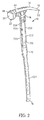
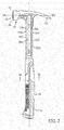
- FIGS 1 and 2 show a hammer 10 in accordance with an embodiment of the present patent application.
- the hammer 10 includes a handle 12 and a head 14.
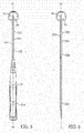
- the handle 12 includes a bottom end 16, an upper portion 18, and a longitudinal axis L--L (as shown in Figures 3 , 4 , 7 and 8 ) extending in a swing plane SP--SP (as shown in Figures 5, 6 , 9, 10 , 14 and 15 ) of the hammer 10.
- the head 14 is disposed on the upper portion 18 of the handle 12.
- the head has a strike face 20, and the strike face 20 has a longitudinal axis SFL--SFL (as shown in Figures 3 , 4 , 7 and 8 ) extending in the SP--SP swing plane of the hammer.
- a majority of the longitudinal length of the handle 12 has a longitudinal rib portion 210 on a first side 206 of the handle 12 and a longitudinal recess portion 212 on a second side 214 of the handle 12.
- the first side 206 of the handle 12 and the second side 214 of the handle 12 generally face opposite directions that are perpendicular to the swing plane SP--SP.
- a majority of the longitudinal length of the handle 12 has the longitudinal rib portion 210 on one side 206 of the swing plane SP--SP and the longitudinal recess portion 212 on the opposite side 214 of the swing plane SP--SP.
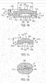
- the rib/recess configuration takes the form of a concavo-convex shaped cross-sectional configuration (shown and described in detail with respect to Figures 14 and 15 ) taken at a plane (e.g., plane T--T or plane T 1 --T 1 as shown in Figure 8 ) that is perpendicular to the central longitudinal axis L--L (as shown in Figures 3 , 4 , 7 and 8 ) of the hammer 10.
- the concavo-convex shaped cross-sectional configuration portion 226 of the handle 12 is flanked by two longitudinal flat areas 228 but other shapes may be used.
- the longitudinal flat end portions 228 have opposite parallel sides.
- the longitudinal flat end portions 228 are disposed on opposite sides of the longitudinal projection 210 and the longitudinal recess 212.
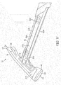
- At least a portion of the handle 12 has the protruding or rib portion 210 on one side 206 thereof and the recess portion 212 on the opposing side 214 thereof, where the protruding portion 210 is formed by displacing an amount of material corresponding to the recess portion 212 from one side 214 of the handle 12 to the other side 206 of the handle 12. That is, as shown in Figures 1 , 2 , 7 , 8 , 14 and 17 , this protruding portion 210 is protrusive on the side 206 of the shaft 12 and recessive on the opposite side 214 of the shaft 12.
- a convex surface 232 (as shown in Figure 14 ) of the curved or concavo-convex shaped cross-sectional portion 226 of the handle 12 generally forms the protruding portion 210.
- a concave surface 230 (as shown in Figure 14 ) of the curved or concavo-convex shaped cross-sectional portion 226 of the handle 12 generally forms the recess portion 212.
- the protruding portion 210 e.g., raised rib
- the recess portion 212 of the handle 12 extends through most of the length of the hammer handle 12.
- the upper and lower ranges for the total percentage of the length of the hammer that is protruding or recessed are 100% and 5%, respectively.
- the terms “shaft” and “handle” may be used interchangeably, unless otherwise prescribed.
- the handle 12 has an overall handle width dimension HW measured in millimeters and a maximum handle thickness dimension HT measured in millimeters taken at the plane T--T that is perpendicular to the central longitudinal axis L--L of the hammer 10.
- a ratio of the maximum handle thickness dimension HT to the overall handle width dimension HW is less than 0.75.
- the ratio of the maximum handle thickness dimension HT to the overall handle width dimension HW is less than 0.4.
- the ratio of the maximum handle thickness dimension HT to the overall handle width dimension HW is between 0.75 and 0.05.
- the ratio of the maximum handle thickness dimension HT to the overall handle width dimension HW is between 0.6 and 0.1.
- the ratio of the maximum handle thickness dimension HT to the overall handle width dimension HW for the illustrated hammer of the present patent application having the maximum handle thickness dimension HT of 6.8 millimeters and the overall handle width dimension HW of 26.04 millimeters is 0.261. In one embodiment, the ratio of the maximum handle thickness dimension HT to the overall handle width dimension HW is 0.274, 0.248, 0.287, 0.235, 0.313, or 0.209.
- the ratio of the maximum handle thickness dimension HT to the overall handle width dimension HW for a framer hammer having the maximum handle thickness dimension HT of 7 millimeters and the overall handle width dimension HW of 26 millimeters is 0.269. In another embodiment, the ratio of the maximum handle thickness dimension HT to the overall handle width dimension HW for a nailer hammer having the maximum handle thickness dimension HT of 7 millimeters and the overall handle width dimension HW of 25 millimeters is 0.28.
- the ratio of the maximum handle thickness dimension HT to the overall handle width dimension HW drops to 0.135.
- the ratio of the maximum handle thickness dimension HT to the overall handle width dimension HW increases to 0.538.
- the ratio of the maximum handle thickness dimension HT to the overall handle width dimension HW is 0.183. Specifically, in this case, the maximum handle thickness dimension HT is 4.75 millimeters and the overall handle width dimension HW is 26 millimeters. In one embodiment, when a rib portion of a hammer has a thickness of 9.25 millimeters and the overall handle width dimension HW is 26 millimeters, the ratio of the maximum handle thickness dimension HT to the overall handle width dimension HW is 0.356.
- the handle 12 includes recess portions or reduced thickness portions 212 on one side thereof and projection/rib portions or increased thickness portions 210 disposed thereon on the opposite side.
- the maximum handle thickness dimension HT of the handle 12 is a thickness measurement measured at the section at portions of the handle 12 where the thickness of the handle is maximum. In one embodiment, the maximum handle thickness dimension HT is measured from the surface 206 of the longitudinal projection 210 on the one side of the handle 12 to the surface 208 of a portion of the second side on which the longitudinal recess 212 is not disposed.
- the maximum handle thickness dimension HT is measured in millimeters from the left-most side surface 208 of the handle 12 to the right-most side surface 206, taken along the transverse plane T--T as shown.
- the longitudinal projection 210 has a projection width dimension PW measured in millimeters taken at the plane T--T that is perpendicular to the central longitudinal axis L--L of the hammer 10 and the handle has the overall handle width dimension HW measured in millimeters taken at the plane T--T that is perpendicular to the central longitudinal axis L--L of the hammer 10.
- a ratio of the projection width dimension PW to the overall handle width dimension HW is less than 0.7.
- a ratio of the projection width dimension PW to the overall handle width dimension HW is less than 0.95.
- the ratio of the projection width dimension PW to the overall handle width dimension HW is between 0.95 and 0.05.
- the ratio of the projection width dimension PW to the overall handle width dimension HW is between 0.6 and 0.7.
- the ratio of the projection width dimension PW to the overall handle width dimension HW of a nailer hammer having a projection width dimension PW of 16.78 millimeters and an overall width dimension HW of 25 millimeters is 0.67. In another embodiment, the ratio of the projection width dimension PW to the overall handle width dimension HW of a framer hammer having a projection width dimension PW of 17 millimeters and an overall width dimension HW of 26 millimeters is 0.65.
- the ratio of the projection width dimension PW to the overall handle width dimension HW for the illustrated hammer having the maximum handle thickness dimension HT of 16.18 millimeters and the overall handle width dimension HW of 26.04 millimeters is 0.621. In one embodiment, the ratio of the projection width dimension PW to the overall handle width dimension HW is 0.652, 0.59, 0.683, 0.559, 0.745, or 0.497.
- the projection may be almost as wide as the shaft of the hammer. In such an embodiment, the ratio of the projection width dimension PW to the overall handle width dimension HW approaches 1. In another embodiment, the projection width may shrink down to one time the material thickness or 4.75 millimeters. In such an embodiment, the ratio of the projection width dimension PW of 4.75 millimeters to the overall handle width dimension HW of 26 millimeters is 0.18.
- the longitudinal recess 212 has a recess width dimension RW measured in millimeters taken at the plane T--T that is perpendicular to the central longitudinal axis L--L of the hammer 10 and the handle 12 has an overall handle width dimension HW measured in millimeters taken at the plane T--T that is perpendicular to the central longitudinal axis L--L of the hammer 10.
- a ratio of the recess width dimension RW to the overall handle width dimension HW is less than 0.95.
- the ratio of the recess width dimension RW to the overall handle width dimension HW is between 0.95 and 0.05.
- the ratio of the recess width dimension RW to the overall handle width dimension HW of a framer hammer having a recess width dimension RW of 14.95 millimeters and an overall width dimension HW of 26 millimeters is 0.575. In another embodiment, the ratio of the recess width dimension RW to the overall handle width dimension HW of a nailer hammer having a recess width dimension RW of 15.48 millimeters and an overall width dimension HW of 25 millimeters is 0.62.
- the ratio of the recess width dimension RW to the overall handle width dimension HW for the illustrated hammer having the recess width dimension RW of 15.215 millimeters and the overall handle width dimension HW of 26.04 millimeters is 0.584.
- the ratio of the projection width dimension PW to the overall handle width dimension HW is 0.613, 0.555, 0.643, 0.526, 0.701, or 0.467.
- the recess may be almost as wide as the width of the shaft. In such an embodiment, the ratio of the recess width dimension RW to the overall handle width dimension HW approaches 1. In another embodiment, the hammer may not include a recess portion. In such an embodiment, the ratio of the recess width dimension RW to the overall handle width dimension HW approaches 0.
- the projection width dimension PW is a width dimension measured from one end of projection 210 to the other, opposite end of the projection 210.
- the recess width dimension RW is a width dimension measured from one end of recess 212 to the other, opposite end of the recess 212.
- the projection width dimension PW is same as the recess width dimension RW.
- the longitudinal projection 210 has a projection height dimension PH measured in millimeters taken at taken at the plane T--T that is perpendicular to the central longitudinal axis L--L of the hammer 10.
- the longitudinal recess 212 has a recess depth dimension RD measured in millimeters taken at the plane T--T that is perpendicular to the central longitudinal axis L--L of the hammer 10.
- the projection height dimension PH is measured from the swing plane SP--SP of the hammer 10 to the surface 206 of the longitudinal projection 210 on the one side of the handle 12.
- a ratio of the projection height dimension PH to the recess depth dimension RD is less than 1.05. In another embodiment, the ratio of the projection height dimension PH to the recess depth dimension RD is less than 3. In one embodiment, the ratio of the projection height dimension PH to the recess depth dimension RD is between 3 and 0.5. In another embodiment, the ratio of the projection height dimension PH to the recess depth dimension RD is between 1.2 and 0.8.
- the ratio of the projection height dimension PH to recess depth dimension RD for the illustrated hammer having the projection height dimension PH of 4.56 millimeters and the recess depth dimension RD of 2.24 millimeters is 2.036. In one embodiment, the ratio of the projection height dimension PH to the recess depth dimension RD is 2.138, 1.934, 2.4, 1.832, 2.443, or 1.629.
- the ratio of the height of the projection to the depth of the recess is approximately 1, i.e., the height of the projection is approximately equal to the depth of the recess, for example, when the hammer is made by stamping a sheet metal material. If the ratio is measured inside the coining details (i.e., decorative pockets) of the shaft, then the ratio of the height of the projection to depth of the recess may decrease to roughly 0.84.
- the height of the projection is greater than the depth of the recess. In another embodiment, the height of the projection is less than the depth of the recess. In one embodiment, when the height of the projection is greater/less than the depth of the recess, the hammer may be formed using a forged part. In such an embodiment, the ratio of the height of the projection to the depth of the recess is greater than 1. In one embodiment, if the height of the projection is three times the depth of the recess, the ratio of the height of the projection to the depth of the recess is approximately 3. In another embodiment, if the recess is two times as deep as the height of the projection, the ratio of the height of the projection to the depth of the recess is approximately 0.5.
- the hammer 10 includes an overall length dimension OAL (as shown in Figure 3 ).
- the overall length dimension OAL of the hammer 10 is measured along (or relative to) the central longitudinal axis L--L of the hammer 10.
- the overall length dimension OAL is measured from the bottom-most end surface 16 of the handle 12 to a top most end 54 of the head 14, taken along central longitudinal axis L--L as shown.
- the weight of the hammer 10 is nominally between 10 and 50 ounces; and the overall length dimension OAL of the hammer 10 is between 12 and 18 inches.
- the weight of the head of the hammer measured at a plane perpendicular to the swing plane and parallel to the central axis of the bell portion that is 2 inches from the top of the head of the hammer, is between 10 and 30 ounces.
- the head 14 of the hammer 10 includes the striking surface 20 at one end 22 thereof, and a pair of tapered, spaced-apart nail removing claws 36 at the opposing end 23.
- the nail removing claws 36 of the head 14 of the hammer 10 are spaced apart so as to provide a V-shaped space 38 (as shown in Figures 5, 6 , 11, 12 , 17 and 18 ) therebetween.
- the shank of a nail can be received in the V-shaped space 38 with the top of the hammer 10 facing the work piece and the nail is removed by engaging the spaced apart claws 36 with the head of the nail and withdrawing the nail from a work piece.
- no claw is provided (e.g., a ball peen hammer).
- the head 14 of the hammer 10 is made of steel, iron, titanium, or other suitable metal material.
- a bell portion 44 located at the forward portion of the head 14 of the hammer 10 includes the striking surface 20.
- a chamfer or bevel 48 is located circumferentially along the edges of the striking surface 20 of the hammer 10.
- the striking surface 20 of the hammer 10 is slightly convex in order to facilitate square contact during driving of nails.
- the head 14 of the hammer 10 is disposed at the upper portion 18 of the handle 12.
- the head 14 of the hammer 10 is integrally formed with the upper portion 18 of the handle 12.
- the handle has a metal (e.g., steel or titanium) shaft integrally formed with the head of the same material.
- a covering of different material e.g., an elastomer material
- the head and the handle are formed separately and then connected to one another.
- the head 14 of the hammer 10 may be mounted on the upper portion 18 of the handle 12 by securing the upper portion 18 of the handle 12 into a portion (e.g., an eye portion) of the head 14 of the hammer 10. Any suitable manner of connecting the head 14 and handle 12 may be employed.
- the handle shaft 12 can be made from a different material than the head 14.
- one or more recesses 272 are located adjacent to but spaced from the striking surface 20 of the head 14.
- a relatively large striking surface 20 is provided without substantially increasing the overall weight of the overall hammer 10 or of the head 14 by providing these recesses 272.
- the handle 12 can be formed by stamping, forging, or other known process.
- a groove 64 is located along a top surface of the bell 44.
- the groove 64 is constructed and arranged to receive and retain a nail (not shown) therein, when the nail is placed in an initial nail driving position to facilitate the start of a nail driving operation.
- an opening or groove 66 may be disposed on the bell portion 44 and is configured to receive a magnet 67 therein.
- the magnet 67 is constructed and arranged to help retain the nail in the initial nail driving position in the groove 64 to facilitate the start of the nail driving operation.
- a notch 70 is disposed on the top surface of the bell portion 44 and a surface 69 of the hammer 10 is constructed and arranged to support a head of the nail.
- the groove 64, the magnet 67, and the surface 69 act together to position and to initially drive the nail in a first blow into a work piece.
- the nail starter arrangement that includes the groove 64, the magnet 67, and the surface 69 are optional.
- the handle 12 is made of metal, a composite material, or a synthetic material.
- the handle 12 of the hammer 10 is made of a lighter material, such as wood, aluminum, a plastic material, a fiberglass material, or other suitable material.
- the handle 12 includes an upper handle portion 222 and a lower handle portion 224.
- the lower handle portion 224 is configured to receive a manually engageable gripping portion 24 thereon.
- the gripping portion 24 is simply the outer surface of the handle material (e.g., wood or metal).
- gripping portion 24 of the hammer 10 is molded onto an inner or core portion 216 (as shown in Figure 4 ) of the handle 12.
- the gripping portion 24 of the handle 12 is made of an elastomeric material, a rubber based material, a plastic based material or other suitable material.
- the gripping portion 24 can be ergonomically shaped.
- a core member 216 of the handle 12 has protrusions and or other similar structures to provide a mechanical interface for the overmolded material (i.e., material of the gripping portion 24).
- the overmolded material i.e., material of the gripping portion 24
- protrusion 218 and through hole 220 are provided on the core member 216 that enable a mechanical bond to be formed between the core member 216 and the material of the gripping portion 24 that is overmolded thereon.
- the protrusion 218 and through hole 220 provide interlocks for the material of the gripping portion 24 to take hold of the core member 216.
- the through holes 220 allow the material of the gripping portion 24 to flow/pass therethrough.
- the material of the gripping portion 24 is configured to conform to the concavo-convex cross-sectional shaped configuration of the core member 216 of the handle 12. That is, the material of the gripping portion 24 is configured to flow into the recess portion 212 (i.e., portion adjacent concave surface 230) and to surround the protruding portion 210. In one embodiment, the recessed portion 212 and the protruding portion 210 of the core member 216 enable a mechanical bond to be formed between the core member 216 of the handle 12 and the gripping portion 24.
- the shaft or handle of the hammer of the present patent application is made of a steel material
- the hammer is inherently resilient to an overstrike.
- the swing plane of the hammer is a plane, which, as viewed in Figures 5, 6 , 9 and 10 , is perpendicular to the page and extends longitudinally through the center of the hammer 10.
- the swing plane SP--SP of the hammer is shown in Figures 5, 6 , 9, 10 , 14 and 15 .
- the striking surface 20 strikes an object, such as a nail or a chisel.
- the swing plane SP--SP of the hammer 10 is generally perpendicular to a plane that passes through the central longitudinal axis L--L (as shown in Figures 3 , 4 , 7 and 8 ) of the hammer 10.
- the swing plane SP--SP of the hammer 10 is also generally perpendicular to the transverse planes T--T and T 1 --T 1 (as shown in Figure 8 ) of the hammer 10.
- the plane that passes through the central longitudinal axis L--L (as shown in Figures 3 , 4 , 7 and 8 ) of the hammer 10 is also generally perpendicular to the transverse planes T--T and T 1 --T 1 (as shown in Figure 8 ) of the hammer 10.
- the transverse planes T--T and T 1 --T 1 (as shown in Figure 8 ), the plane that passes through the central longitudinal axis L--L (as shown in Figures 3 , 4 , 7 and 8 ), and the swing plane SP--SP of the hammer 10 are perpendicular to each other.
- the transverse plane T 1 --T 1 is parallel and spaced-apart from the transverse plane T--T and both the transverse planes T 1 --T 1 and T--T are perpendicular to the central longitudinal axis L--L of the hammer 10.
- the hammer 10 includes the overall handle width dimension HW.
- the overall handle width dimension HW of the hammer 10 is measured at the transverse plane T--T that is perpendicular to the central longitudinal axis L--L of the hammer 10.
- the overall handle width dimension HW is measured in millimeters from a front surface 202 to a rear surface 204 of the handle 12, taken along the transverse plane T--T as shown.
- the hammer 10 includes the maximum handle thickness (depth or height) dimension HT.
- the maximum handle thickness dimension HT of the hammer 10 is measured at the transverse plane T--T of the hammer 10.
- the maximum handle thickness dimension HT is measured in millimeters from the left-most side surface 208 of the handle 12 to the right-most side surface 206, taken along the transverse plane T--T as shown.
- the overall handle width HW of the hammer 10 is between 24.5 and 26.5 millimeters; and the maximum handle thickness HT of the hammer 10 is between 6.5 and 7.5 millimeters.
- the lateral stiffness of the shaft 12 in this present patent application is a function of the cross-sectional shape of the shaft 12 and the height of the protruding portion 210 of the shaft 12.
- the ratio of the maximum shaft height dimension HT (measured in millimeters) to the overall shaft width dimension HW (measured in millimeters) is an important feature of this present patent application.
- the ratio of the maximum handle thickness dimension HT to the overall handle width dimension HW is less than 0.75.
- the ratio of the maximum handle thickness dimension HT to the overall handle width dimension HW is less than 0.4.
- the ratio is between 0.75 and 0.05.
- the ratio is between 0.6 and 0.1.
- the cross-sectional configuration of the core member 216 of the handle 12 taken at the transverse plane T--T i.e., perpendicular to the central longitudinal axis L--L of the hammer 10) is shown in Figure 14 and the cross-sectional configuration of the core member 216 of the handle 12 taken at the transverse plane T 1 --T 1 (i.e., perpendicular to the central longitudinal axis L--L of the hammer 10) is shown in Figure 15 .
- the cross-sectional configuration of the core member 216 of the handle 12 generally has the concavo-convex shaped cross-sectional configuration portion 226.
- the concavo-convex shaped cross-sectional configuration portion 226 includes the convex surface 232 forming the protruding portion 210 on one side 206 of the hammer 10 and the concave surface 230 forming the recess portion 212 on the opposing side 214 of the hammer 10.
- the hammer 10 includes the end portions 228 disposed at ends of the concavo-convex shaped cross-sectional configuration portion 226.
- the end portions 228 generally have rectangular cross-sectional configuration.
- the convex surface 232 of the concavo-convex shaped cross-sectional configuration portion 226 projects beyond the portion of rectangular cross-sectional configuration of the end portions 228 by an amount corresponding to the depth of the recess portion 212.
- the concavo-convex shaped cross-sectional configuration portion 226 is asymmetrical about the swing plane SP--SP of the hammer 10.
- This asymmetrical concavo-convex shaped cross-sectional configuration portion 226 of the handle 10 is adapted to increase the lateral stiffness of the handle.
- the lack of symmetry in the concavo-convex shaped cross-sectional configuration portion 226 (i.e., about the swing plane SP--SP of the hammer 10) is seen clearly in Figures 14 and 15 .
- the concavo-convex shaped cross-sectional configuration portion 226 is offset with respect to the swing plane SP--SP of the hammer 10. That is, the upper portion of the concavo-convex shaped cross-sectional configuration portion 226 is offset to one side of the swing plane SP--SP of the hammer 10.
- the lower handle portion 224 has an overall handle width dimension HW L and the upper handle portion 222 has an overall handle width dimension HW U .
- the overall handle width dimension HW L of the lower handle portion 224 and the overall handle width dimension HW U of the upper handle portion 222 are measured at the transverse planes T 1 --T 1 and T--T, respectively, of the hammer 10.
- the overall handle width dimension HW L of the lower handle portion 224 is different from the overall handle width dimension HW U of the upper handle portion 222.
- the overall handle width dimension HW L of the lower handle portion 224 is smaller than the overall handle width dimension HW U of the upper handle portion 222 so as to maintain a light weight configuration of the hammer while providing the desired lateral stiffness to the handle 12.
- the overall handle width dimension HW U of the upper handle portion 222 is higher than the overall handle width dimension HW L of the lower handle portion 224 so as to provide the desired lateral stiffness to the handle 12.
- the width of the hammer shaft in the upper portion 222 HW U is increased relative to the width HW L of the lower portion 224 in order to provide the desired lateral stiffness to the handle 12.
- the overall handle width dimension HW L of the lower handle portion 224 may be same as the overall handle width dimension HW U of the upper handle portion 222.
- the overall handle width dimension HW L of the lower handle portion 224 may be greater than the overall handle width dimension HW U of the upper handle portion 222.
- the overall handle width dimension HW L of the lower handle portion may be greater than the overall handle width dimension HW U of the upper handle portion, for example, in a 10 ounces welded hammer.
- the lower handle portion 224 has a maximum handle thickness dimension HT L and the upper handle portion 222 has a maximum handle thickness dimension HT U .
- the maximum handle thickness dimension HT L of the lower handle portion 224 and the maximum handle thickness dimension HT U of the upper handle portion 222 are measured at the transverse planes T 1 --T 1 and T--T, respectively, of the hammer 10.
- the maximum handle thickness dimension HT L of the lower handle portion 224 is same as the maximum handle thickness dimension HT U of the upper handle portion 222. In another embodiment, the maximum handle thickness dimension HT L of the lower handle portion 224 may be different from the maximum handle thickness dimension HT U of the upper handle portion 222. In one embodiment, the maximum upper handle portion thickness dimension HT U is greater than the maximum lower handle portion thickness dimension HT L .
- the cross-sectional configuration of the core member 216 of the handle 12 taken at the transverse plane T 1 --T 1 is very similar to that of the cross-sectional configuration of the core member 216 of the handle 12 taken at the transverse plane T--T, except for the noted difference.
- the overall handle width dimension HW L of the lower handle portion 224 is smaller as the overall handle width dimension HW U of the upper handle portion 222, therefore, the cross-sectional configuration of the core member 216 of the handle 12 taken at the transverse plane T 1 --T 1 is generally narrower than that of the cross-sectional configuration of the core member 216 of the handle 12 taken at the transverse plane T--T.
- Figures 14 and 15 show portions and dimensions of the handle core portion of the hammer 10 in accordance with an embodiment of the present patent application.
- the portions and dimensions of the handle core portion of the hammer 10 shown in Figures 14 and 15 are intended to be merely exemplary and not limiting in any way.
- the portions and dimensions of the handle core portion of the hammer 10 shown in Figures 14 and 15 are drawn to scale in accordance with one embodiment, although other scales and shapes may be used in other embodiments.
- the dimensions of the handle core portion as shown in Figures 14 and 15 are measured in millimeters unless indicated otherwise.
- the dimensions of the handle core portion of the hammer 10, as shown in Figures 14 and 15 and as described in the present patent application are up to 10 percent greater than or up to 10 percent less than those illustrated.
- the dimensions of various parts of the hammer 10, as shown in Figures 14 and 15 and as described in the present patent application are up to 5 percent greater than or up to 5 percent less than those illustrated.
- the dimensions of various parts of the hammer 10, as shown in Figures 14 and 15 and as described in the present patent application are up to 20 percent greater than or up to 20 percent less than those illustrated.
- the tolerance is ⁇ 0.25 millimeters. In one embodiment, for dimensions having two digits after the decimal place, the tolerance is ⁇ 0.1 millimeters.
- the handle described in the present patent application may be used, for example, in the hammer disclosed in U.S. Patent Serial No. 13/605,151 , which is hereby incorporated by reference in its entirety.
- the hammer shaft or handle of the present patent application is constructed and arranged to provide a high lateral stiffness (or strength) while maintaining a light weight configuration. As discussed above, in one embodiment, the present patent application achieves this very high lateral stiffness (i.e., while keeping the shaft or handle weight low), for example, by making the cross sectional shape along the swing plane asymmetrical.
Landscapes
- Engineering & Computer Science (AREA)
- Mechanical Engineering (AREA)
- Percussive Tools And Related Accessories (AREA)
- Food-Manufacturing Devices (AREA)
Applications Claiming Priority (1)
| Application Number | Priority Date | Filing Date | Title |
|---|---|---|---|
| US14/025,314 US9193059B2 (en) | 2013-09-12 | 2013-09-12 | Hammer with bend resistant handle |
Publications (3)
| Publication Number | Publication Date |
|---|---|
| EP2848372A2 true EP2848372A2 (de) | 2015-03-18 |
| EP2848372A3 EP2848372A3 (de) | 2016-03-09 |
| EP2848372B1 EP2848372B1 (de) | 2017-01-11 |
Family
ID=51494186
Family Applications (1)
| Application Number | Title | Priority Date | Filing Date |
|---|---|---|---|
| EP14184202.1A Active EP2848372B1 (de) | 2013-09-12 | 2014-09-10 | Hammer mit biegesteifem Griff |
Country Status (2)
| Country | Link |
|---|---|
| US (1) | US9193059B2 (de) |
| EP (1) | EP2848372B1 (de) |
Cited By (2)
| Publication number | Priority date | Publication date | Assignee | Title |
|---|---|---|---|---|
| EP4299179A1 (de) * | 2022-06-28 | 2024-01-03 | Funai Electric Co., Ltd. | Grundierungsvorrichtung und grundierungsverfahren für flüssigkeitskartusche und flüssigkeitsabgabevorrichtung |
| EP4470723A1 (de) * | 2023-05-31 | 2024-12-04 | Techtronic Cordless GP | Schlagwerkzeug |
Families Citing this family (31)
| Publication number | Priority date | Publication date | Assignee | Title |
|---|---|---|---|---|
| GB2541304B (en) | 2014-03-07 | 2020-12-02 | Estwing Mfg Company | Striking tool with attached striking surface |
| NZ724384A (en) | 2014-03-07 | 2019-07-26 | Estwing Mfg Company Inc | Aluminum striking tools |
| USD788562S1 (en) | 2014-06-05 | 2017-06-06 | Estwing Manufacturing Company, Inc. | Hammer |
| US20160039078A1 (en) * | 2014-08-05 | 2016-02-11 | Joshua D. West | Hammer |
| USD777549S1 (en) * | 2015-02-16 | 2017-01-31 | Yi-Kung Hung | Hammer |
| USD781124S1 (en) * | 2015-06-25 | 2017-03-14 | Lucky-Brand Industrial Co., Ltd. | Hammer |
| US10464198B1 (en) * | 2016-03-06 | 2019-11-05 | David Edward Steidtmann | Hammer with lightweight handle |
| CA171532S (en) * | 2016-07-11 | 2017-06-20 | Jiangsu Sainty Sumex Tools Corp Ltd | Hammer |
| USD829074S1 (en) | 2016-09-21 | 2018-09-25 | Estwing Manufacturing Company, Inc. | Hammer |
| USD837019S1 (en) * | 2016-11-18 | 2019-01-01 | Milwaukee Electric Tool Corporation | Hammer |
| USD837021S1 (en) * | 2016-11-18 | 2019-01-01 | Milwaukee Electric Tool Corporation | Hammer |
| USD825308S1 (en) * | 2017-01-11 | 2018-08-14 | Cheng-Tung Hsu | Hammer |
| US11358263B2 (en) | 2018-02-21 | 2022-06-14 | Milwaukee Electric Tool Corporation | Hammer |
| USD862191S1 (en) * | 2018-03-09 | 2019-10-08 | Stanley Black & Decker, Inc. | Axe |
| USD872555S1 (en) * | 2018-05-30 | 2020-01-14 | Fiskars Finland Oy Ab | Hammer |
| US11337885B1 (en) * | 2018-08-30 | 2022-05-24 | Eric Conley | Handled soft tissue mobilization devices and methods for making same |
| USD897805S1 (en) * | 2018-12-28 | 2020-10-06 | Stanley Black & Decker, Inc. | Hammer handle |
| US11833651B2 (en) | 2019-02-07 | 2023-12-05 | Milwaukee Electric Tool Corporation | Hammer with hardened textured striking face |
| USD910402S1 (en) * | 2019-09-18 | 2021-02-16 | Daniel J. Raymond | Hammer |
| USD910403S1 (en) * | 2019-09-18 | 2021-02-16 | Daniel J. Raymond | Hammer |
| EP4087708A4 (de) | 2020-01-10 | 2024-01-24 | Milwaukee Electric Tool Corporation | Hammer |
| USD924032S1 (en) * | 2020-02-18 | 2021-07-06 | Lu Kang Hand Tools Industrial Co., Ltd. | American-type hammer |
| USD935297S1 (en) * | 2020-05-07 | 2021-11-09 | Garant Gp | Tool handle with a grip |
| USD936444S1 (en) * | 2020-05-07 | 2021-11-23 | Garant Gp | Tool handle with a grip |
| CN112936190A (zh) * | 2021-01-22 | 2021-06-11 | 赵彦巧 | 野外勘测用多功能地质锤 |
| USD973460S1 (en) * | 2021-03-04 | 2022-12-27 | Apex Brands, Inc. | Hammer |
| DE202021103854U1 (de) * | 2021-07-20 | 2021-08-05 | Lucky-Brand Industrial Co., Ltd. | Hammerwerkzeug für die Positionierung von Doppelkopfnägeln |
| USD1011857S1 (en) * | 2022-03-10 | 2024-01-23 | Js Products, Inc. | Striking tool |
| USD1011165S1 (en) * | 2022-03-10 | 2024-01-16 | Js Products, Inc. | Striking tool |
| WO2025106373A1 (en) * | 2023-11-14 | 2025-05-22 | Stanley Black & Decker, Inc. | Head retention for striking tool |
| US20250282043A1 (en) * | 2024-03-08 | 2025-09-11 | Daniel J. Raymond | Hammer handle |
Family Cites Families (6)
| Publication number | Priority date | Publication date | Assignee | Title |
|---|---|---|---|---|
| US2729253A (en) * | 1954-12-07 | 1956-01-03 | Hardware Products Co | Hammer with tubular handle having reinforcing means |
| US2837381A (en) * | 1955-11-21 | 1958-06-03 | Oscar L Sarlandt | Reinforced tool handle attachment |
| US5768956A (en) * | 1996-03-28 | 1998-06-23 | Coonrad; Todd Douglas | Striking tool |
| US6149538A (en) * | 1996-07-19 | 2000-11-21 | Tiura; Oliver | Handle for striking device |
| CN101992462B (zh) * | 2009-08-14 | 2015-08-19 | 杭州巨星科技股份有限公司 | 工具手柄及其制造方法 |
| US20130126807A1 (en) * | 2011-11-22 | 2013-05-23 | Stanley Black & Decker, Inc. | Welded hammer |
-
2013
- 2013-09-12 US US14/025,314 patent/US9193059B2/en active Active
-
2014
- 2014-09-10 EP EP14184202.1A patent/EP2848372B1/de active Active
Cited By (2)
| Publication number | Priority date | Publication date | Assignee | Title |
|---|---|---|---|---|
| EP4299179A1 (de) * | 2022-06-28 | 2024-01-03 | Funai Electric Co., Ltd. | Grundierungsvorrichtung und grundierungsverfahren für flüssigkeitskartusche und flüssigkeitsabgabevorrichtung |
| EP4470723A1 (de) * | 2023-05-31 | 2024-12-04 | Techtronic Cordless GP | Schlagwerkzeug |
Also Published As
| Publication number | Publication date |
|---|---|
| US9193059B2 (en) | 2015-11-24 |
| EP2848372A3 (de) | 2016-03-09 |
| US20150068366A1 (en) | 2015-03-12 |
| EP2848372B1 (de) | 2017-01-11 |
Similar Documents
| Publication | Publication Date | Title |
|---|---|---|
| EP2848372B1 (de) | Hammer mit biegesteifem Griff | |
| US10717181B2 (en) | Roofing and nail removal hammer | |
| US7874231B2 (en) | Striking tool | |
| EP2743037B1 (de) | Vibrationsgedämpfter Hammer | |
| US20160039078A1 (en) | Hammer | |
| US10213932B2 (en) | Handle protector for a hand tool | |
| US8141458B1 (en) | Hammer head with recessed traction striking surface | |
| US20120091409A1 (en) | Striking tools | |
| US9789597B2 (en) | Striking tool with attached striking surface | |
| US7143667B2 (en) | Striking or pulling tool with a split head | |
| US9233462B2 (en) | Hammer | |
| US9802304B2 (en) | Aluminum striking tools | |
| US9815216B1 (en) | Apparatus for splitting wood into kindling | |
| US4336832A (en) | Non-slip hammer | |
| CN207888579U (zh) | 一种工具 | |
| US8424212B2 (en) | Apparatus for splitting wood into kindling | |
| US4718313A (en) | Hammer head for a hammer | |
| KR200428389Y1 (ko) | 보강요홈이 요설된 고무망치 몸체. | |
| KR20190001801U (ko) | 못 타격 펀치 |
Legal Events
| Date | Code | Title | Description |
|---|---|---|---|
| PUAI | Public reference made under article 153(3) epc to a published international application that has entered the european phase |
Free format text: ORIGINAL CODE: 0009012 |
|
| 17P | Request for examination filed |
Effective date: 20140910 |
|
| AK | Designated contracting states |
Kind code of ref document: A2 Designated state(s): AL AT BE BG CH CY CZ DE DK EE ES FI FR GB GR HR HU IE IS IT LI LT LU LV MC MK MT NL NO PL PT RO RS SE SI SK SM TR |
|
| AX | Request for extension of the european patent |
Extension state: BA ME |
|
| PUAL | Search report despatched |
Free format text: ORIGINAL CODE: 0009013 |
|
| AK | Designated contracting states |
Kind code of ref document: A3 Designated state(s): AL AT BE BG CH CY CZ DE DK EE ES FI FR GB GR HR HU IE IS IT LI LT LU LV MC MK MT NL NO PL PT RO RS SE SI SK SM TR |
|
| AX | Request for extension of the european patent |
Extension state: BA ME |
|
| RIC1 | Information provided on ipc code assigned before grant |
Ipc: B25D 1/04 20060101ALI20160203BHEP Ipc: B25G 1/10 20060101AFI20160203BHEP |
|
| R17P | Request for examination filed (corrected) |
Effective date: 20160824 |
|
| RBV | Designated contracting states (corrected) |
Designated state(s): AL AT BE BG CH CY CZ DE DK EE ES FI FR GB GR HR HU IE IS IT LI LT LU LV MC MK MT NL NO PL PT RO RS SE SI SK SM TR |
|
| GRAP | Despatch of communication of intention to grant a patent |
Free format text: ORIGINAL CODE: EPIDOSNIGR1 |
|
| INTG | Intention to grant announced |
Effective date: 20161021 |
|
| STAA | Information on the status of an ep patent application or granted ep patent |
Free format text: STATUS: GRANT OF PATENT IS INTENDED |
|
| GRAS | Grant fee paid |
Free format text: ORIGINAL CODE: EPIDOSNIGR3 |
|
| GRAA | (expected) grant |
Free format text: ORIGINAL CODE: 0009210 |
|
| STAA | Information on the status of an ep patent application or granted ep patent |
Free format text: STATUS: THE PATENT HAS BEEN GRANTED |
|
| AK | Designated contracting states |
Kind code of ref document: B1 Designated state(s): AL AT BE BG CH CY CZ DE DK EE ES FI FR GB GR HR HU IE IS IT LI LT LU LV MC MK MT NL NO PL PT RO RS SE SI SK SM TR |
|
| REG | Reference to a national code |
Ref country code: GB Ref legal event code: FG4D |
|
| REG | Reference to a national code |
Ref country code: CH Ref legal event code: EP |
|
| REG | Reference to a national code |
Ref country code: AT Ref legal event code: REF Ref document number: 860828 Country of ref document: AT Kind code of ref document: T Effective date: 20170115 |
|
| REG | Reference to a national code |
Ref country code: IE Ref legal event code: FG4D |
|
| REG | Reference to a national code |
Ref country code: DE Ref legal event code: R096 Ref document number: 602014006160 Country of ref document: DE |
|
| REG | Reference to a national code |
Ref country code: LT Ref legal event code: MG4D |
|
| REG | Reference to a national code |
Ref country code: NL Ref legal event code: MP Effective date: 20170111 |
|
| REG | Reference to a national code |
Ref country code: AT Ref legal event code: MK05 Ref document number: 860828 Country of ref document: AT Kind code of ref document: T Effective date: 20170111 |
|
| PG25 | Lapsed in a contracting state [announced via postgrant information from national office to epo] |
Ref country code: NL Free format text: LAPSE BECAUSE OF FAILURE TO SUBMIT A TRANSLATION OF THE DESCRIPTION OR TO PAY THE FEE WITHIN THE PRESCRIBED TIME-LIMIT Effective date: 20170111 |
|
| PG25 | Lapsed in a contracting state [announced via postgrant information from national office to epo] |
Ref country code: NO Free format text: LAPSE BECAUSE OF FAILURE TO SUBMIT A TRANSLATION OF THE DESCRIPTION OR TO PAY THE FEE WITHIN THE PRESCRIBED TIME-LIMIT Effective date: 20170411 Ref country code: LT Free format text: LAPSE BECAUSE OF FAILURE TO SUBMIT A TRANSLATION OF THE DESCRIPTION OR TO PAY THE FEE WITHIN THE PRESCRIBED TIME-LIMIT Effective date: 20170111 Ref country code: HR Free format text: LAPSE BECAUSE OF FAILURE TO SUBMIT A TRANSLATION OF THE DESCRIPTION OR TO PAY THE FEE WITHIN THE PRESCRIBED TIME-LIMIT Effective date: 20170111 Ref country code: FI Free format text: LAPSE BECAUSE OF FAILURE TO SUBMIT A TRANSLATION OF THE DESCRIPTION OR TO PAY THE FEE WITHIN THE PRESCRIBED TIME-LIMIT Effective date: 20170111 Ref country code: IS Free format text: LAPSE BECAUSE OF FAILURE TO SUBMIT A TRANSLATION OF THE DESCRIPTION OR TO PAY THE FEE WITHIN THE PRESCRIBED TIME-LIMIT Effective date: 20170511 Ref country code: GR Free format text: LAPSE BECAUSE OF FAILURE TO SUBMIT A TRANSLATION OF THE DESCRIPTION OR TO PAY THE FEE WITHIN THE PRESCRIBED TIME-LIMIT Effective date: 20170412 |
|
| REG | Reference to a national code |
Ref country code: FR Ref legal event code: PLFP Year of fee payment: 4 |
|
| PG25 | Lapsed in a contracting state [announced via postgrant information from national office to epo] |
Ref country code: LV Free format text: LAPSE BECAUSE OF FAILURE TO SUBMIT A TRANSLATION OF THE DESCRIPTION OR TO PAY THE FEE WITHIN THE PRESCRIBED TIME-LIMIT Effective date: 20170111 Ref country code: RS Free format text: LAPSE BECAUSE OF FAILURE TO SUBMIT A TRANSLATION OF THE DESCRIPTION OR TO PAY THE FEE WITHIN THE PRESCRIBED TIME-LIMIT Effective date: 20170111 Ref country code: AT Free format text: LAPSE BECAUSE OF FAILURE TO SUBMIT A TRANSLATION OF THE DESCRIPTION OR TO PAY THE FEE WITHIN THE PRESCRIBED TIME-LIMIT Effective date: 20170111 Ref country code: PT Free format text: LAPSE BECAUSE OF FAILURE TO SUBMIT A TRANSLATION OF THE DESCRIPTION OR TO PAY THE FEE WITHIN THE PRESCRIBED TIME-LIMIT Effective date: 20170511 Ref country code: BG Free format text: LAPSE BECAUSE OF FAILURE TO SUBMIT A TRANSLATION OF THE DESCRIPTION OR TO PAY THE FEE WITHIN THE PRESCRIBED TIME-LIMIT Effective date: 20170411 Ref country code: SE Free format text: LAPSE BECAUSE OF FAILURE TO SUBMIT A TRANSLATION OF THE DESCRIPTION OR TO PAY THE FEE WITHIN THE PRESCRIBED TIME-LIMIT Effective date: 20170111 Ref country code: ES Free format text: LAPSE BECAUSE OF FAILURE TO SUBMIT A TRANSLATION OF THE DESCRIPTION OR TO PAY THE FEE WITHIN THE PRESCRIBED TIME-LIMIT Effective date: 20170111 Ref country code: PL Free format text: LAPSE BECAUSE OF FAILURE TO SUBMIT A TRANSLATION OF THE DESCRIPTION OR TO PAY THE FEE WITHIN THE PRESCRIBED TIME-LIMIT Effective date: 20170111 |
|
| REG | Reference to a national code |
Ref country code: DE Ref legal event code: R097 Ref document number: 602014006160 Country of ref document: DE |
|
| PG25 | Lapsed in a contracting state [announced via postgrant information from national office to epo] |
Ref country code: RO Free format text: LAPSE BECAUSE OF FAILURE TO SUBMIT A TRANSLATION OF THE DESCRIPTION OR TO PAY THE FEE WITHIN THE PRESCRIBED TIME-LIMIT Effective date: 20170111 Ref country code: SK Free format text: LAPSE BECAUSE OF FAILURE TO SUBMIT A TRANSLATION OF THE DESCRIPTION OR TO PAY THE FEE WITHIN THE PRESCRIBED TIME-LIMIT Effective date: 20170111 Ref country code: EE Free format text: LAPSE BECAUSE OF FAILURE TO SUBMIT A TRANSLATION OF THE DESCRIPTION OR TO PAY THE FEE WITHIN THE PRESCRIBED TIME-LIMIT Effective date: 20170111 Ref country code: IT Free format text: LAPSE BECAUSE OF FAILURE TO SUBMIT A TRANSLATION OF THE DESCRIPTION OR TO PAY THE FEE WITHIN THE PRESCRIBED TIME-LIMIT Effective date: 20170111 Ref country code: CZ Free format text: LAPSE BECAUSE OF FAILURE TO SUBMIT A TRANSLATION OF THE DESCRIPTION OR TO PAY THE FEE WITHIN THE PRESCRIBED TIME-LIMIT Effective date: 20170111 |
|
| PLBE | No opposition filed within time limit |
Free format text: ORIGINAL CODE: 0009261 |
|
| STAA | Information on the status of an ep patent application or granted ep patent |
Free format text: STATUS: NO OPPOSITION FILED WITHIN TIME LIMIT |
|
| PG25 | Lapsed in a contracting state [announced via postgrant information from national office to epo] |
Ref country code: SM Free format text: LAPSE BECAUSE OF FAILURE TO SUBMIT A TRANSLATION OF THE DESCRIPTION OR TO PAY THE FEE WITHIN THE PRESCRIBED TIME-LIMIT Effective date: 20170111 Ref country code: DK Free format text: LAPSE BECAUSE OF FAILURE TO SUBMIT A TRANSLATION OF THE DESCRIPTION OR TO PAY THE FEE WITHIN THE PRESCRIBED TIME-LIMIT Effective date: 20170111 |
|
| 26N | No opposition filed |
Effective date: 20171012 |
|
| PG25 | Lapsed in a contracting state [announced via postgrant information from national office to epo] |
Ref country code: SI Free format text: LAPSE BECAUSE OF FAILURE TO SUBMIT A TRANSLATION OF THE DESCRIPTION OR TO PAY THE FEE WITHIN THE PRESCRIBED TIME-LIMIT Effective date: 20170111 |
|
| REG | Reference to a national code |
Ref country code: CH Ref legal event code: PL |
|
| PG25 | Lapsed in a contracting state [announced via postgrant information from national office to epo] |
Ref country code: MC Free format text: LAPSE BECAUSE OF FAILURE TO SUBMIT A TRANSLATION OF THE DESCRIPTION OR TO PAY THE FEE WITHIN THE PRESCRIBED TIME-LIMIT Effective date: 20170111 |
|
| REG | Reference to a national code |
Ref country code: IE Ref legal event code: MM4A |
|
| REG | Reference to a national code |
Ref country code: BE Ref legal event code: MM Effective date: 20170930 |
|
| PG25 | Lapsed in a contracting state [announced via postgrant information from national office to epo] |
Ref country code: LU Free format text: LAPSE BECAUSE OF NON-PAYMENT OF DUE FEES Effective date: 20170910 |
|
| PG25 | Lapsed in a contracting state [announced via postgrant information from national office to epo] |
Ref country code: LI Free format text: LAPSE BECAUSE OF NON-PAYMENT OF DUE FEES Effective date: 20170930 Ref country code: CH Free format text: LAPSE BECAUSE OF NON-PAYMENT OF DUE FEES Effective date: 20170930 Ref country code: IE Free format text: LAPSE BECAUSE OF NON-PAYMENT OF DUE FEES Effective date: 20170910 |
|
| REG | Reference to a national code |
Ref country code: FR Ref legal event code: PLFP Year of fee payment: 5 |
|
| PG25 | Lapsed in a contracting state [announced via postgrant information from national office to epo] |
Ref country code: BE Free format text: LAPSE BECAUSE OF NON-PAYMENT OF DUE FEES Effective date: 20170930 |
|
| PG25 | Lapsed in a contracting state [announced via postgrant information from national office to epo] |
Ref country code: MT Free format text: LAPSE BECAUSE OF NON-PAYMENT OF DUE FEES Effective date: 20170910 |
|
| PGFP | Annual fee paid to national office [announced via postgrant information from national office to epo] |
Ref country code: FR Payment date: 20180813 Year of fee payment: 5 |
|
| PG25 | Lapsed in a contracting state [announced via postgrant information from national office to epo] |
Ref country code: HU Free format text: LAPSE BECAUSE OF FAILURE TO SUBMIT A TRANSLATION OF THE DESCRIPTION OR TO PAY THE FEE WITHIN THE PRESCRIBED TIME-LIMIT; INVALID AB INITIO Effective date: 20140910 |
|
| PG25 | Lapsed in a contracting state [announced via postgrant information from national office to epo] |
Ref country code: CY Free format text: LAPSE BECAUSE OF FAILURE TO SUBMIT A TRANSLATION OF THE DESCRIPTION OR TO PAY THE FEE WITHIN THE PRESCRIBED TIME-LIMIT Effective date: 20170111 |
|
| PG25 | Lapsed in a contracting state [announced via postgrant information from national office to epo] |
Ref country code: MK Free format text: LAPSE BECAUSE OF FAILURE TO SUBMIT A TRANSLATION OF THE DESCRIPTION OR TO PAY THE FEE WITHIN THE PRESCRIBED TIME-LIMIT Effective date: 20170111 |
|
| PG25 | Lapsed in a contracting state [announced via postgrant information from national office to epo] |
Ref country code: TR Free format text: LAPSE BECAUSE OF FAILURE TO SUBMIT A TRANSLATION OF THE DESCRIPTION OR TO PAY THE FEE WITHIN THE PRESCRIBED TIME-LIMIT Effective date: 20170111 |
|
| PG25 | Lapsed in a contracting state [announced via postgrant information from national office to epo] |
Ref country code: AL Free format text: LAPSE BECAUSE OF FAILURE TO SUBMIT A TRANSLATION OF THE DESCRIPTION OR TO PAY THE FEE WITHIN THE PRESCRIBED TIME-LIMIT Effective date: 20170111 |
|
| PG25 | Lapsed in a contracting state [announced via postgrant information from national office to epo] |
Ref country code: FR Free format text: LAPSE BECAUSE OF NON-PAYMENT OF DUE FEES Effective date: 20190930 |
|
| PGFP | Annual fee paid to national office [announced via postgrant information from national office to epo] |
Ref country code: DE Payment date: 20250919 Year of fee payment: 12 |
|
| PGFP | Annual fee paid to national office [announced via postgrant information from national office to epo] |
Ref country code: GB Payment date: 20250923 Year of fee payment: 12 |