EP2848442B1 - Dachvorrichtung - Google Patents
Dachvorrichtung Download PDFInfo
- Publication number
- EP2848442B1 EP2848442B1 EP14184881.2A EP14184881A EP2848442B1 EP 2848442 B1 EP2848442 B1 EP 2848442B1 EP 14184881 A EP14184881 A EP 14184881A EP 2848442 B1 EP2848442 B1 EP 2848442B1
- Authority
- EP
- European Patent Office
- Prior art keywords
- weather strip
- panel
- border
- opening
- seal
- Prior art date
- Legal status (The legal status is an assumption and is not a legal conclusion. Google has not performed a legal analysis and makes no representation as to the accuracy of the status listed.)
- Active
Links
Images


Classifications
-
- B—PERFORMING OPERATIONS; TRANSPORTING
- B60—VEHICLES IN GENERAL
- B60J—WINDOWS, WINDSCREENS, NON-FIXED ROOFS, DOORS, OR SIMILAR DEVICES FOR VEHICLES; REMOVABLE EXTERNAL PROTECTIVE COVERINGS SPECIALLY ADAPTED FOR VEHICLES
- B60J7/00—Non-fixed roofs; Roofs with movable panels, e.g. rotary sunroofs
- B60J7/02—Non-fixed roofs; Roofs with movable panels, e.g. rotary sunroofs of sliding type, e.g. comprising guide shoes
- B60J7/04—Non-fixed roofs; Roofs with movable panels, e.g. rotary sunroofs of sliding type, e.g. comprising guide shoes with rigid plate-like element or elements, e.g. open roofs with harmonica-type folding rigid panels
- B60J7/043—Sunroofs e.g. sliding above the roof
- B60J7/0435—Sunroofs e.g. sliding above the roof pivoting upwardly to vent mode and moving at the outside of the roof to fully open mode
-
- B—PERFORMING OPERATIONS; TRANSPORTING
- B60—VEHICLES IN GENERAL
- B60J—WINDOWS, WINDSCREENS, NON-FIXED ROOFS, DOORS, OR SIMILAR DEVICES FOR VEHICLES; REMOVABLE EXTERNAL PROTECTIVE COVERINGS SPECIALLY ADAPTED FOR VEHICLES
- B60J10/00—Sealing arrangements
- B60J10/20—Sealing arrangements characterised by the shape
- B60J10/21—Sealing arrangements characterised by the shape having corner parts or bends
-
- B—PERFORMING OPERATIONS; TRANSPORTING
- B60—VEHICLES IN GENERAL
- B60J—WINDOWS, WINDSCREENS, NON-FIXED ROOFS, DOORS, OR SIMILAR DEVICES FOR VEHICLES; REMOVABLE EXTERNAL PROTECTIVE COVERINGS SPECIALLY ADAPTED FOR VEHICLES
- B60J10/00—Sealing arrangements
- B60J10/40—Sealing arrangements characterised by contact between two or more cooperating sealing arrangements
-
- B—PERFORMING OPERATIONS; TRANSPORTING
- B60—VEHICLES IN GENERAL
- B60J—WINDOWS, WINDSCREENS, NON-FIXED ROOFS, DOORS, OR SIMILAR DEVICES FOR VEHICLES; REMOVABLE EXTERNAL PROTECTIVE COVERINGS SPECIALLY ADAPTED FOR VEHICLES
- B60J10/00—Sealing arrangements
- B60J10/80—Sealing arrangements specially adapted for opening panels, e.g. doors
- B60J10/82—Sealing arrangements specially adapted for opening panels, e.g. doors for movable panels in roofs
Definitions
- This disclosure generally relates to a roof apparatus.
- Patent reference 1 A known roof apparatus is disclosed in JP2010-95129A (hereinafter referred to as Patent reference 1).
- the roof apparatus disclosed in Patent reference 1 includes plural panels which cover an opening formed at a roof of a vehicle.
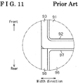
- a panel frame body 92 is provided and fixed to an entire periphery of a rim portion of a front panel 91 which is positioned at a front of the vehicle.
- a weather strip 93 is attached to an entire periphery of the panel frame body 92.
- a panel frame body 97 is provided and fixed to an entire periphery of a rim portion of a rear panel 96 which is positioned at a rear of the vehicle.
- a weather strip 98 is attached to an entire periphery of the panel frame body 97 except for a front rim portion thereof.
- the weather strip 93 liquid-tightly contacts an opening rim of the opening closer to a front of the vehicle and a front rim of the panel frame body 97, whereas the weather strip 98 liquid-tightly contacts the opening rim of the opening closer to the rear of the vehicle.
- a sealing function is assured to an entire periphery of the opening together with a border portion between the front panel 91 and the rear panel 96.
- the sealing is cut at a side portion of the border portion between the front panel 91 and the rear panel 96 because it is difficult to assure the sealing function at a portion between the weather strip 93 and a front rim of the weather strip 98.
- the side portion may allow infiltration of rainwater.
- Patent reference 2 Another known roof apparatus is disclosed in JP2012-96766A (hereinafter, referred to as Patent reference 2).
- a weather strip is attached to an entire periphery of an opening of a roof.
- a sealing function of a border portion between a movable panel which is positioned at a front of a vehicle and a fixed panel which is positioned at a rear of the vehicle is assured by a weather strip attached on a front rim portion of, for example, the fixed panel.
- the sealing is cut at a side portion of the border ortion.
- Yet another roof apparatus is known from DE 103 45 855 A1 and discloses the preamble of claim 1.
- a roof apparatus includes plural panels being positioned next to each other in a vehicle front-rear direction, the plural panels configured to a roof to cover an opening formed on the roof of the vehicle, the plural panels including a first panel for opening and closing the opening, the plural panels including a second panel being positioned at a front or a rear of the vehicle and next to the first panel, the second panel being fixed to establish a state where the opening is closed.
- the roof apparatus further includes a weather strip including a weather strip body being attached to an entire periphery of the opening of the roof, the weather strip body sealing a portion between an opening rim of the opening and a peripheral rim formed by the plural panels, a border weather strip attached to the second panel at a border portion between the first panel and the second panel which are positioned next to each other, the border weather strip sealing the border portion between the first panel and the second panel, and a connection portion integrally connecting the weather strip body and each opposing end of the border weather strip in a vehicle width direction.
- a weather strip including a weather strip body being attached to an entire periphery of the opening of the roof, the weather strip body sealing a portion between an opening rim of the opening and a peripheral rim formed by the plural panels, a border weather strip attached to the second panel at a border portion between the first panel and the second panel which are positioned next to each other, the border weather strip sealing the border portion between the first panel and the second panel, and a connection portion integrally connecting the weather strip body
- the portion between the peripheral rim of the first panel and the opening rim of the opening, and the border portion between the first panel and the second panel are sealed by the single weather strip.
- the portion between the peripheral rim of the second panel and the opening rim of the opening, and the border portion between the second panel and the first panel are sealed by the single weather strip.
- the sealing may be prevented from being cut at the entire periphery of the opening including the border portion between the first panel and the second panel.
- the weather strip body includes a first side-portion weather strip and a second side-portion weather strip serving as a pair, the first side-portion weather strip and the second side-portion weather strip extending in the vehicle front-rear direction along opposing rim portions of the opening in the vehicle width direction, respectively.
- Each of the first side-portion weather strip and the second side-portion weather strip is made from an extruded member having a constant cross section
- said each of the first side-portion weather strip and the second side-portion weather strip includes an attachment portion configured to be attached to the roof
- said each of the first side-portion weather strip and the second side-portion weather strip includes a first seal portion connected to the attachment portion and liquid-tightly contacts the opening rim of the opening
- said each of the first side-portion weather strip and the second side-portion weather strip includes a second seal portion connected to the attachment portion and liquid-tightly contacts the peripheral rim formed by the first panel and the second panel.
- the connection portion connects the first side-portion weather strip and the second side-portion weather strip with each end of the border weather strip while leaving at least the first seal portion.
- the cross-sectional shape of the first seal portion may be maintained when being positioned at the connection portion. Accordingly, the sealing performance may be prevented from being varied between the first seal portion and the opening rim of the opening.
- connection portion connects the first side-portion weather strip and the second side-portion weather strip with said each end of the border weather strip while leaving the first seal portion and the attachment portion.
- the cross-sectional shape of the attachment portion in addition to the first seal portion may be maintained when being positioned at the connection portion.
- the sealing performance may be prevented from being varied between the first seal portion and the opening rim of the opening.
- the border weather strip is made from an extruded member having a constant cross section.
- the connection portion includes a gradually changed portion whose cross-sectional shape is gradually changed from a cross-sectional shape of the border weather strip to a cross-sectional shape of at least the second seal portion and vice versa.
- the gradually changed portion may prevent the cross-sectional shape of the second seal portion from being changed sharply.
- the second seal portion forms a hollow cross section together with the attachment portion by connecting ends of the second seal portion to the attachment portion.
- the border weather strip includes a panel attachment portion attached to the second panel.
- the border weather strip further includes a third seal portion connected to the panel attachment portion and liquid-tightly contacts a rim end of the first panel facing the second panel in the vehicle front-rear direction.
- the border weather strip further includes a fourth seal portion connected to the panel attachment portion and liquid-tightly contacts the rim end of the second panel facing the first panel in the vehicle front-rear direction.
- the fourth seal portion forms a non-hollow cross section together with the panel attachment portion by being cantilevered by the panel attachment portion.
- the cross-sectional shape of the gradually changed portion is gradually changed from the hollow cross-sectional shape formed by the second seal portion to the non-hollow cross-sectional shape formed by the fourth seal portion and vice versa.
- the second seal portion and the fourth seal portion which include different cross-sectional shapes from each other may be connected smoothly by the gradually changed portion.
- the second panel includes a base panel which is made of metal and is configured to fix the second panel to the roof.
- the base panel includes a receiving portion receiving reaction force applied to the connection portion from the first panel which is in a fully-closed state.
- the reaction force applied to the connection portion from the first panel is received by the receiving portion which serves as a part of the metal-made base panel. Accordingly, for example, the sealing performance may not be degraded due to the instability of the posture of the connection portion when elastically deformed.
- the weather strip body includes a first side-portion weather strip and a second side-portion weather strip serving as a pair, the first side-portion weather strip and the second side-portion weather strip extending in the vehicle front-rear direction along opposing rim portions of the opening in the vehicle width direction, respectively.
- Each of the first side-portion weather strip and the second side-portion weather strip is made from an extruded member having a constant cross section
- said each of the first side-portion weather strip and the second side-portion weather strip includes an attachment portion configured to be attached to the roof
- said each of the first side-portion weather strip and the second side-portion weather strip includes a first seal portion connected to the attachment portion and liquid-tightly contacts the opening rim of the opening
- said each of the first side-portion weather strip and the second side-portion weather strip includes a second seal portion connected to the attachment portion and liquid-tightly contacts the peripheral rim formed by the first panel and the second panel.
- connection portion is connected to the first side-portion weather strip and the second side-portion weather strip so as to be replaced with a portion of the first side-portion weather strip and the second side-portion weather strip, the portion including an entire width of the first side-portion weather strip and the second side-portion weather strip in the vehicle width direction, and the portion including an entire length of the border weather strip in the vehicle front-rear direction.
- the sealing by the weather strip may be prevented from being cut.
- a front-rear direction corresponds to a front-rear direction of a vehicle
- an upward and a downward correspond to an upward and a downward in a vehicle height direction
- a width direction corresponds a width direction of the vehicle.
- a vehicle inner side corresponds to the inner in a vehicle width direction directed to an inside of a vehicle compartment
- a vehicle outer side corresponds to the outer in the vehicle width direction directed to an outside of the vehicle compartment.
- a substantially quadrilateral opening 11 is formed on a roof 10 of a vehicle, for example, an automobile.
- An opening rim of the opening 11 includes a body-side flange portion 11a which is formed in a substantially quadrilateral tube extending downward of a substantially entire periphery of the opening 11.
- a movable panel 12 i.e., serving as a first panel
- a fixed panel 13 i.e., serving as a second panel
- the movable panel 12 serving as a first panel is provided to open and close a front portion of the opening 11.
- the movable panel 12 is provided to perform a tilt-up operation in which a rear portion of the movable panel 12 is raised with a front portion of the movable panel 12 as a rotation center and a sliding operation in the front-rear direction.
- An outer sliding type in which the movable panel 12 slides while maintaining a tilt-up state, is adopted for an opening and closing operation of the front portion of the opening 11.
- the movable panel 12 includes a first rim portion 12a formed in a substantially quadrilateral loop shape along a peripheral rim portion of the movable panel 12 and is made from, for example, a resin material.
- the fixed panel 13 serving as a second panel is attached to always close a rear portion of the opening 11.
- the fixed panel 13 includes a second rim portion 13a formed in a substantially quadrilateral loop shape along a peripheral rim portion of the fixed panel 13 and is made from, for example, a resin material.
- a pair of guide rails 14 extending in the front-rear direction along opposing rim portions of the opening 11 in the width direction is provided at the roof 10. Further, a front housing 16 extends along a front rim portion of the opening 11 and connects each of front ends of the guide rails 14 at the roof 10 in the width direction, whereas a rear housing 17 extends along a rear rim portion of the opening 11 and connects each of rear ends of the guide rails 14 at the roof 10 in the width direction.
- Each of the guide rails 14 is made from an extruded member, for example, aluminum alloy, whereas the front housing 16 and the rear housing 17 are made from, for example, a resin material.
- a pair of function members is movably supported on the opposing guide rails 14 in the front-rear direction.
- the movable panel 12 is linked and supported on the function members so as to be extended thereover.
- the movable panel 12 opens and closes in accordance with the movement of the function members in the front-rear direction.
- a weather strip 20 is mounted to the roof 10.
- the weather strip 20 includes a weather strip body 21, a border weather strip 25, and connection portions 26.
- the weather strip body 21 formed in a substantially quadrilateral loop shape is provided along a peripheral rim portion of the opening 11.
- the border weather strip 25 extends along a front rim portion of the fixed panel 13 in the width direction.
- the connection portion 26 made by die forming integrally connects the weather strip body 21 and opposing ends of the border weather strip 25 in the width direction, respectively.
- the weather strip body 21 includes a pair of side-portion weather strips 22 (i.e., serving as a first side-portion weather strip and a second side-portion weather strip) and a pair of front/rear portion weather strips 23.
- the pair of side-portion weather strips 22 extends in the front-rear direction along the opposing rim portions of the opening 11 in the width direction.
- the pair of front/rear portion weather strips 23 extends in the width direction along the opposing rim portions of the opening 11 in the front-rear direction.
- Front-rear portion weather strips 23 serving as a pair connect to a front end of the side-portion weather strip 22 and to a rear end of the side-portion weather strip 22, respectively, via a corner portion 24 which is made by die forming.
- Each of the side-portion weather strips 22 is made from an extruded member which has a substantially constant cross section in the front-rear direction, whereas the front-rear portion weather strips 23 and the border weather strip 25 are made from extruded members which have substantially constant cross sections, respectively, in the width direction.
- each of the side-portion weather strips 22 is attached on the guide rail 14 and seals a portion between the body-side flange portion 11a of the opening 11 and each rim end of the movable panel 12 and the fixed panel 13 at opposing sides in the width direction. That is, the opposing end rims in the width direction and a rear end rim of the second rim portion 13a of the fixed panel 13 include a panel-side flange portion 13b extending downward of the substantially entire length of the second rim portion 13a.
- Each of the guide rails 14 includes a wall 15 formed in a substantial longitudinal shape and standing upwardly over the substantially entire length in the longitudinal direction of the guide rails 14.
- the side-portion weather strip 22 includes an attachment portion 31, a first seal portion 32, and a second seal portion 33.
- the attachment portion 31 includes a cross section which is formed in a substantially C-shape and sandwiches and fits an upper portion of the wall 15.
- the first seal portion 32 is curved to protrude towards the vehicle outer side from the attachment portion 31.
- the second seal portion 33 is curved to protrude towards the vehicle inner side from the attachment portion 31.
- the attachment portion 31 is made from a solid material of synthetic rubber, for example, ethylene propylene dien monomer, or EPDM, or of thermoplastic elastomer, whereas the first and second seal portions 32, 33 are made from sponge material of the synthetic rubber, for example, EPDM or of the thermoplastic elastomer.
- a first end of the first seal portion 32 is connected to an upper end of the attachment portion 31, whereas a second end of the first seal portion 32 is connected to a lower end of the attachment portion 31 at the vehicle outer side relative to the wall 15.
- the first seal portion 32 is formed to have a substantially bow shape in cross section and protrudes towards the vehicle outer side (i.e., towards the body-side flange portion 11 a).
- the first seal portion 32 formed in a substantially D-shape in a cross section together with the attachment portion 31 elastically deforms, or resiliently reforms so as to overlap with a portion of the body-side flange portion 11 a in the vehicle height direction and liquid-tightly contacts therewith.
- a first end of the second seal portion 33 is connected to the upper end of the attachment portion 31, whereas a second end of the second seal portion 33 is connected to the lower end of the attachment portion 31 at the vehicle inner side relative to the wall 15.
- the second seal portion 33 is formed to have a substantially bow shape in cross section and protrudes towards the vehicle inner side (i.e., towards the panel-side flange portion 13b).
- the second seal portion 33 formed in a substantially D-shape in a cross section together with the attachment portion 31 elastically deforms, or resiliently reforms so as to overlap with a portion of the panel-side flange portion 13b in the vehicle height direction and liquid-tightly contacts therewith.
- opposing end rims in the width direction and a front end rim of the first rim portion 12a of the movable panel 12 include a panel-side flange portion 12b extending downward of the substantially entire length of the first rim portion 12a.
- the second seal portion 33 elastically deforms, or resiliently reforms so as to overlap with a portion of the panel-side flange portion 12b of the fully-closed movable panel 12 in the vehicle height direction and liquid-tightly contacts therewith.
- the front housing 16 is provided with a mounted wall which is similar to the wall 15, whereas the front-rear portion weather strip 23 positioned at the front of the vehicle is provided with an attachment portion, a first seal portion and a second seal portion which are similar to the attachment portion 31, the first seal portion 32, and the second seal portion 33.
- the front-rear weather strip 23 includes the attachment portion which sandwiches and fits an upper portion of the mounted wall of the front housing 16.
- the first seal portion liquid-tightly contacts the body-side flange portion 11 a, whereas the second seal portion liquid-tightly contacts the panel-side flange portion 12b of the fully-closed movable panel 12.
- the rear housing 17 is provided with a mounted wall which is similar to the wall 15, whereas the front-rear portion weather strip 23 positioned at the rear of the vehicle is provided with an attachment portion, a first seal portion and a second seal portion which are similar to the attachment portion 31, the first seal portion 32, and the second seal portion 33.
- the front-rear weather strip 23 includes the attachment portion which sandwiches and fits an upper portion of the mounted wall of the rear housing 17.
- the first seal portion liquid-tightly contacts the body-side flange portion 11a, whereas the second seal portion liquid-tightly contacts the panel-side flange portion 13b of the fixed panel 13.
- the border weather strip 25 is attached to the front rim portion of the fixed panel 13 and seals a border portion (clearance) between the fully-closed movable panel 12 and the fixed panel 13. That is, as shown in Fig. 5 , a panel-side engagement protrusion 13c formed in a substantially hooked shape in cross section is positioned at the front end rim of the second rim portion 13a of the fixed panel 13 and protrudes from a lower portion toward the front of the vehicle.
- a seal-side engagement protrusion 25a serving as a panel attachment portion formed in a substantially hooked shape in cross section protrudes from an upper portion towards the rear of the vehicle so as to engage with, from different directions, the panel-side engagement protrusion 13c of the fixed panel 13 which protrudes from a lower portion towards the front of the vehicle.
- the border weather strip 25 includes a third seal portion 25b and a fourth seal portion 25c.
- the third seal portion 25b is curved to protrude from the seal-side engagement protrusion 25a to the front of the vehicle.
- the fourth seal portion 25c protrudes from the seal-side engagement protrusion 25a to the rear of the vehicle.
- the seal-side engagement protrusion 25a is made from a solid material of synthetic rubber, for example, EPDM, or of thermoplastic elastomer, whereas the third and fourth seal portions 25b, 25c are made from sponge material of the synthetic rubber, for example, EPDM or of the thermoplastic elastomer.
- a first end of the third seal portion 25b is connected to an upper end of the seal-side engagement protrusion 25a, whereas a second end of the third seal portion 25b is connected a lower end of the seal-side engagement protrusion 25a.
- the third seal portion 25b is formed to have a substantially bow shape in cross section and protrudes towards the front of the vehicle (i.e., towards the panel-side flange portion 12b of the movable panel 12).
- the third seal portion 25b is formed in a substantially D-shape in a hollow cross section together with the seal-side engagement protrusion 25a and elastically deforms, or resiliently reforms so as to overlap with a portion of the panel-side flange portion 12b in the vehicle height direction and liquid-tightly contacts therewith.
- a first end of the fourth seal portion 25c is cantilevered and connected to the upper end of the seal-side engagement protrusion 25a.
- the fourth seal portion 25c is formed in a substantially lip shape in cross section and extends towards the rear of the vehicle (i.e., towards the second rim portion 13a of the fixed panel 13). That is, the fourth seal portion 25c includes a non-hollow cross section together with the seal-side engagement protrusion 25a and liquid-tightly contacts the panel-side flange portion 13b.
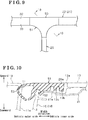
- connection portions 26 are made from the synthetic rubber, for example, EPDM or from the thermoplastic elastomer, and as shown in Fig. 2 , the connection portion 26 is formed in a substantially T shape in a plan view extending to be gradually wider towards the vehicle outer side.
- An end of the connection portion 26 positioned at the vehicle outer side is connected to the second seal portion 33 so as to be replaced with a portion of the second seal portion 33, the portion including an entire length of the border weather strip 25 in the front-rear direction.
- An end of the connection portion 26 positioned at the vehicle inner side is connected to an end of the border weather strip 25.
- the connection portion 26 faces and comes close contact with the first rim portion 12a of the fully-closed movable panel 12 at the front side portion while facing and coming close contact with the second rim portion 13a of the fixed panel 13 at the rear side portion.
- connection portions 26 is supported by the fixed panel 13. That is, as shown in Fig. 3 , the fixed panel 13 includes a substantially quadrilateral frame-shaped base panel 41 which is made from a steel plate and is positioned downwardly along the peripheral rim portion. The base panel 41 fixes the fixed panel 13 to the roof 10. Further, as shown in Fig. 6 in addition to Fig. 3 , the base panel 41 includes a support wall portion 41a positioned at a corner portion of the second rim portion 13a which faces the connection portion 26 and extending toward the front of the vehicle relative to the second rim portion 13a. The connection portion 26 is mounted on the support wall portion 41 a.
- connection portion 26 includes an engagement protrusion 26a formed in a substantially hooked shape in cross section, protruding from the vehicle outer side to downward and engaging with, from different directions, the panel-side engagement protrusion 13c of the fixed panel 13 protruding from the vehicle inner side to upward at a corner portion of the second rim portion 13a which faces the connection portion 26.
- the connection portion 26 is fixed to the fixed panel 13 by engaging the engagement protrusion 26a with the panel-side engagement protrusion 13c.
- the base panel 41 includes a receiving portion 41 b which is formed in a pawl shape and stands upwardly from the end of the support wall portion 41a.
- the receiving portion 41 b is curved to have a substantially bow shape along the front side portion of the connection portion 26 where the first rim portion 12a of the fully-closed movable panel 12 comes in close contact therewith.
- the receiving portion 41b is positioned within the connection portion 26 and receives a reaction force which is applied to the connection portion 26 from the movable panel 12, for example, for stabilizing a posture of the connection portion 26 when being elastically deformed. That is, the position of the connection portion 26 is defined by the rim portions 12a, 13a of the movable panel 12 and the fixed panel 13, respectively, and the base panel 41. Accordingly, the sealing function between the movable panel 12 and the fixed panel 13 is assured.
- the base panel 41 includes an extending wall portion 41 c which is placed at a position being interposed by the opposing support wall portions 41a in the width direction and extends towards the front of the vehicle.
- a substantially band-shaped up-down seal portion 29 which is made from synthetic rubber, for example, EPDM or from thermoplastic elastomer is fixed to a front end portion of the extending wall portion 41 c.
- An upper end portion of the up-down seal portion 29 liquid-tightly contacts the bottom surface of the fully-closed movable panel 12.
- the up-down seal portion 29 may be integrally formed with the border weather strip 25.
- the second seal portion 33 of the side-portion weather strip 22 forms a hollow cross section together with the attachment portion 31, whereas the fourth seal portion 25c of the border weather strip 25 forms a non-hollow cross section together with the seal-side engagement protrusion 25a.
- the rear side portion of the connection portion 26 includes a gradually changed portion 27 whose cross-sectional shape is gradually changed from the hollow cross-sectional shape formed by the second seal portion 33 to the non-hollow cross-sectional shape formed by the fourth seal portion 25c, and vice versa as shown a change from Fig. 8 to Fig. 6 . Accordingly, the cross section of the second seal portion 33 is prevented from being changed sharply at the connection portion 26.
- the operation of the roof apparatus according to the embodiment will be explained.
- the movable panel 12 when the movable panel 12 is in a fully-closed state, a portion between the panel-side flange portion 12b of the movable panel 12 and the body-side flange portion 11a of the opening 11, and the border portion between the movable panel 12 and the fixed panel 13 are sealed by the single weather strip 20, that is, the front portion of the weather strip body 21, the border weather strip 25 and each of the connection portions 26 over the entire periphery of the movable panel 12. That is, the movable panel 12 covers and comes close contact with the single opening 11 formed at the front portion of the weather strip 20.
- the fixed panel 13 a portion between the panel-side flange portion 13b of the fixed panel 13 and the body-side flange portion 11 a of the opening 11, and the border portion between the fixed panel 13 and the movable panel 12 are sealed by the single weather strip 20, that is, the rear portion of the weather strip body 21, the border weather strip 25 and each of the connection portions 26 over the entire periphery of the fixed panel 13. That is, the fixed panel 13 covers and comes close contact with the single opening 11 formed at the rear portion of the weather strip 20.
- the sealing of the entire periphery of the opening 11 including the border portion between the movable panel 12 and the fixed panel 13 is prevented from being cut. Accordingly, the leakage of water and air by the opening 11 is prevented.
- a part of the function members protrudes upward from a portion between the panel-side flange portion 12b and the side-portion weather strip 22.
- the portion protruding upward is set not to reach the border weather strip 25.
- the sealing of the entire periphery of the opening 11 including the border portion between the movable panel 12 and the fixed panel 13 is prevented from being cut.
- connection portion 26 connects the side-portion weather strip 22 and the end of the border weather strip 25 while leaving the first seal portion 32. Accordingly, the cross-sectional shape of the first seal portion 32 may be maintained when being positioned at the connection portion 26 and may prevent the sharp variance of the sealing performance between the first seal portion 32 and the body-side flange portion 11 a.
- connection portion 26 connects the side-portion weather strip 22 and the end of the border weather strip 25 while leaving the attachment portion 31 in addition to the first seal portion 32. Accordingly, the cross-sectional shapes of the attachment portion 31 in addition to the first seal portion 32 may be maintained when being positioned at the connection portion 26 and may prevent the sharp variance of the sealing performance between the first seal portion 32 and the body-side flange portion 11 a.
- connection portion 26 includes the gradually changed potion 27 whose cross-sectional shape is gradually changed from the cross-sectional shape of the border weather strip 25 and the cross-sectional shape of at least the second seal portion 33 and vice versa.
- the cross-sectional shape of the second seal portion 33 is prevented from being changed sharply. Accordingly, the sealing performance between the second seal portion 33 and the panel-side flange portion 13b of the fixed panel 13 may be prevented from being changed sharply.
- the cross-sectional shape of the gradually changed portion 27 is gradually changed from the hollow cross-section formed by the second seal portion 33 to the non-hollow cross-section formed by the fourth seal portion 25c and vice versa. Accordingly, the gradually changed portion 27 smoothly connects the second seal portion 33 and the fourth seal portion 25c which include different cross-sectional shapes from each other.
- the receiving portion 41 b which is the part of the metal-made base panel 41 receives the reaction force applied to the connection portion 26 from the fully-closed movable panel 12, the sealing performance may not be degraded due to, for example, the instability of the posture of the connection portion 26 when elastically deformed.
- the base panel 41 is made of metal, sufficient support strength may be assured when positioning the receiving portion 41 b by extending the support wall portion 41 a.
- a die-formed connection portion 51 may be connected to the side-portion weather strip 22 so as to be replaced with a portion of the side-portion 22, the portion including an entire width of the side-portion weather strip 22 in the vehicle width direction, and the portion including the entire length of the border weather strip 25 in the front-rear direction.
- the connection portion 51 faces and comes in close contact with the first rim portion 12a of the fully-closed movable panel 12 at the front side portion of the connection portion 51 while facing and coming in close contact with the second rim portion 13a of the fixed portion 13 at the rear side portion of the connection portion 51.
- connection portion 51 includes an intermediate attachment portion 52 which corresponds to the attachment portion 31 of the embodiment and sandwiches and fits the upper portion of the wall 15. Further, the connection portion 51 includes an intermediate seal portion 53 which corresponds to the first seal portion 32 of the embodiment and liquid-tightly contacts the body-side flange portion 11a.
- the roof apparatus may include a die-formed connection portion being connected to the side-portion weather strip 22 so as to be replaced with a portion of the attachment portion 31 and the second seal portion 33 of the side portion weather strip 22, the portion including the entire length of the border weather strip 25 in the front-rear direction.
- the cross-sectional shape of the first seal portion 32 may be maintained when being positioned at the connection portion and may prevent the variance of the sealing performance between the connection portion and the body-side flange portion 11 a.
- the roof apparatus does not have to include the receiving portion 41 b of the base panel 41.
- the roof apparatus is provided with a gradually changed portion whose cross-sectional shape is gradually changed from the cross-sectional shape of the attachment portion 31 of the side-portion weather strip 22 to the cross-sectional shape of the seal-side engagement protrusion 25a of the border weather strip 25 and vice versa.
- the roof apparatus of the aforementioned embodiment does not have to include the gradually changed portion 27 whose cross-sectional shape is gradually changed from the hollow cross section formed by the second seal portion 33 to the non-hollow cross section formed by the fourth seal portion 25c and vice versa.
- the fourth seal portion 25c of the border weather strip 25 may include a hollow cross section together with the seal-side engagement protrusion 25a.
- each of the side-portion weather strips 22 may be attached to the roof 10 via an applicable bracket.
- a front side of the front-rear portion weather strips 23 may be attached to the roof 10 via an applicable bracket.
- a rear side of the front-rear portion weather strip 23 may be attached to the roof 10 via an applicable bracket, or may be attached to the fixed panel 13.
- three or more panels covering the opening 11 may be arranged next to each other in the front-rear direction as long as the movable panel 12 (the first panel) and the fixed panel 13 (the second panel) may be arranged alternately in the front-rear direction.
- the border weather strip 25 may be positioned between the movable panel 12 and the fixed panel 13 which are positioned next to each other.
Landscapes
- Engineering & Computer Science (AREA)
- Mechanical Engineering (AREA)
- Seal Device For Vehicle (AREA)
Claims (7)
- Dachvorrichtung, mit:einer Mehrzahl Paneele (12, 13), welche in einer Fahrzeuglängsrichtung nebeneinander positioniert sind, wobei die Mehrzahl Paneele (12, 13) an einem Dach (10) ausgebildet ist, um eine in dem Dach (10) des Fahrzeugs ausgebildete Öffnung (11) abzudecken;wobei die Mehrzahl Paneele (12, 13) ein erstes Paneel (12) zum Öffnen und Schließen der Öffnung (11) und ein zweites Paneel (13) beinhaltet, welches vorne oder hinten am Fahrzeug und neben dem ersten Paneel (12) positioniert ist, wobei das zweite Paneel (13) fixiert ist, um einen Zustand zu etablieren, in dem die Öffnung (11) geschlossen ist; undeinem Dichtungsstreifen (20), mit:einem Dichtungsstreifenkörper (21), welcher an einer gesamten Peripherie der Öffnung (11) des Dachs (10) befestigt ist, wobei der Dichtungsstreifenkörper (21) einen Abschnitt zwischen einem Öffnungsrand der Öffnung (11) und einem peripheren Rand abdichtet, welcher durch die Mehrzahl Paneele (12, 13) ausgebildet ist;einem Grenzdichtungsstreifen (25), welcher an dem zweiten Paneel (13) an einem Grenzabschnitt zwischen dem ersten Paneel (12) und dem zweiten Paneel (13) befestigt ist, die nebeneinander positioniert sind, wobei der Grenzdichtungsstreifen (25) den Grenzabschnitt zwischen dem ersten Paneel (12) und dem zweiten Paneel (13) abdichtet; und gekennzeichnet durcheinen Verbindungsabschnitt (26, 51), welcher den Dichtungsstreifenkörper (21) und jedes gegenüberliegende Ende des Grenzdichtungsstreifens (25) in einer Fahrzeugbreitenrichtung integral verbindet.
- Dachvorrichtung gemäß Anspruch 1, wobei:der Dichtungsstreifenkörper (21) einen ersten Seitenabschnitt-Dichtungsstreifen (22) und einen zweiten Seitenabschnitt-Dichtungsstreifen (22) beinhaltet, welche als ein Paar dienen, wobei sich der erste Seitenabschnitt-Dichtungsstreifen (22) und der zweite Seitenabschnitt-Dichtungsstreifen in der Fahrzeuglängsrichtung jeweils entlang sich in der Fahrzeugbreitenrichtung gegenüberliegender Randabschnitte der Öffnung (11) erstrecken;jeder der ersten Seitenabschnitt-Dichtungsstreifen (22) und der zweiten Seitenabschnitt-Dichtungsstreifen (22) aus einem extrudierten Bauteil gemacht ist, welches einen konstanten Querschnitt aufweist, wobei jeder der besagten ersten Seitenabschnitt-Dichtungsstreifen (22) und der zweiten Seitenabschnitt-Dichtungsstreifen (22) einen Befestigungsabschnitt (31) beinhaltet, welcher ausgebildet ist, um am Dach (10) befestigt zu sein, wobei jeder der besagten ersten Seitenabschnitt-Dichtungsstreifen (22) und zweiten Seitenabschnitt-Dichtungsstreifen (22) einen ersten Dichtungsabschnitt (32) beinhaltet, welcher mit dem Befestigungsabschnitt (31) verbunden ist und den Öffnungsrand der Öffnung (11) flüssigkeitsdichtend berührt, und jeder der besagten ersten Seitenabschnitt-Dichtungsstreifen (22) und der zweiten Seitenabschnitt-Dichtungsstreifen (22) einen zweiten Dichtungsabschnitt (33) beinhaltet, welcher mit dem Befestigungsabschnitt (31) verbunden ist und den durch das erste Paneel (12) und das zweite Paneel (13) ausgebildeten peripheren Rand flüssigkeitsdichtend berührt; undder Verbindungsabschnitt (26) den ersten Seitenabschnitt-Dichtungsstreifen (22) und den zweiten Seitenabschnitt-Dichtungsstreifen (22) mit jedem Ende des Grenzdichtungsstreifens (25) verbindet, wobei zumindest der erste Dichtungsabschnitt (32) belassen wird.
- Dachvorrichtung gemäß Anspruch 2, wobei der Verbindungsabschnitt (26) den ersten Seitenabschnitt-Dichtungsstreifen (22) und den zweiten Seitenabschnitt-Dichtungsstreifen (22) mit jedem besagten Ende des Grenzdichtungsstreifens (25) verbindet, wobei der erste Dichtungsabschnitt (32) und der Befestigungsabschnitt (31) belassen werden.
- Dachvorrichtung gemäß entweder Anspruch 2 oder 3, wobei
der Grenzdichtungsstreifen (25) aus einem extrudierten Bauteil gemacht ist, welches einen konstanten Querschnitt aufweist; und
der Verbindungsabschnitt (26) einen sich allmählich ändernden Abschnitt (27) beinhaltet, dessen Querschnittsform sich allmählich von einer Querschnittsform des Grenzdichtungsstreifens (25) zu einer Querschnittsform von zumindest dem zweiten Dichtungsabschnitt (33) ändert und umgekehrt. - Dachvorrichtung gemäß Anspruch 4, wobei
der zweite Dichtungsabschnitt (33) zusammen mit dem Befestigungsabschnitt (31) einen hohlen Querschnitt ausbildet, indem die Enden des zweiten Dichtungsabschnitts (33) mit dem Befestigungsabschnitt (31) verbunden sind;
der Grenzdichtungsstreifen (25) einen Paneelbefestigungsabschnitt (25a) beinhaltet, welcher an dem zweiten Paneel (13) befestigt ist, der Grenzdichtungsstreifen (25) einen dritten Dichtungsabschnitt (25b) beinhaltet, welcher mit dem Paneelbefestigungsabschnitt (25a) verbunden ist und ein Randende des ersten Paneels (12), welches dem zweiten Paneel (13) in der Fahrzeuglängsrichtung zugewandt ist, flüssigkeitsdichtend berührt, und der Grenzdichtungsstreifen (25) einen vierten Dichtungsabschnitt (25c) beinhaltet, welcher mit dem Paneelbefestigungsabschnitt (25a) verbunden ist und ein Randende des zweiten Paneels (13), welches dem ersten Paneel (12) in der Fahrzeuglängsrichtung zugewandt ist, flüssigkeitsdichtend berührt;
der vierte Dichtungsabschnitt (25c) zusammen mit dem Paneelbefestigungsabschnitt (25a) einen nicht-hohlen Querschnitt durch einseitiges Einspannen durch den Paneelbefestigungsabschnitt (25a) ausbildet; und
sich die Querschnittsform des allmählich ändernden Abschnitts (27) von der durch den zweiten Dichtungsabschnitt (33) ausgebildeten hohlen Querschnittsform zu der durch den vierten Dichtungsabschnitt ausgebildeten nicht-hohlen Querschnittsform ändert und umgekehrt. - Dachvorrichtung gemäß einem der Ansprüche 1 bis 5, wobei
das zweite Paneel (13) eine Grundplatte (41) beinhaltet, welche aus Metall hergestellt ist, wobei die Grundplatte (41) ausgebildet ist, um das zweite Paneel (13) an dem Dach (10) zu fixieren; und
die Grundplatte (41) einen Aufnahmeabschnitt (41 b) beinhaltet, welche eine Reaktionskraft aufnimmt, die von dem ersten Paneel (12), welches in einem vollständig geschlossenen Zustand ist, auf den Verbindungsabschnitt (26) ausgeübt wird. - Dachvorrichtung gemäß entweder Anspruch 1 oder 6, wobei
der Dichtungsstreifenkörper (21) einen ersten Seitenabschnitt-Dichtungsstreifen (22) und einen zweiten Seitenabschnitt-Dichtungsstreifen (22) beinhaltet, welche als ein Paar dienen, wobei sich der erste Seitenabschnitt-Dichtungsstreifen (22) und der zweite Seitenabschnitt-Dichtungsstreifen (22) jeweils in der Fahrzeuglängsrichtung entlang sich in der Fahrzeugbreitenrichtung gegenüberliegender Randabschnitte der Öffnung (11) erstrecken;
jeder der ersten Seitenabschnitt-Dichtungsstreifen (22) und der zweiten Seitenabschnitt-Dichtungsstreifen (22) aus einem extrudierten Bauteil gemacht ist, welches einen konstanten Querschnitt aufweist, wobei jeder der besagten ersten Seitenabschnitt-Dichtungsstreifen (22) und der zweiten Seitenabschnitt-Dichtungsstreifen (22) einen Befestigungsabschnitt (31) beinhaltet, welcher ausgebildet ist, um an dem Dach (10) befestigt zu sein, wobei jeder der besagten ersten Seitenabschnitt-Dichtungsstreifen (22) und der zweiten Seitenabschnitt-Dichtungsstreifen (22) einen ersten Dichtungsabschnitt (32) beinhaltet, welcher mit dem Befestigungsabschnitt (31) verbunden ist und den Öffnungsrand der Öffnung (11) flüssigkeitsdichtend berührt und jeder der besagten ersten Seitenabschnitt-Dichtungsstreifen (22) und zweiten Seitenabschnitt-Dichtungsstreifen (22) einen zweiten Dichtungsabschnitt (33) beinhaltet, welcher mit dem Befestigungsabschnitt (31) verbunden ist und den durch das erste Paneel (12) und das zweite Paneel (13) ausgebildeten peripheren Rand flüssigkeitsdichtend berührt; und
der Verbindungsabschnitt (51) mit dem ersten Seitenabschnitt-Dichtungsstreifen (22) und dem zweiten Seitenabschnitt-Dichtungsstreifen (22) verbunden ist, um gegen einen Abschnitt des ersten Seitenabschnitt-Dichtungsstreifens (22) und des zweiten Seitenabschnitt-Dichtungsstreifens (22) ausgewechselt zu werden, wobei der Abschnitt eine Gesamtbreite des ersten Seitenabschnitt-Dichtungsstreifens (22) und des zweiten Seitenabschnitt-Dichtungsstreifens (22) in der Fahrzeugbreitenrichtung umfasst, und der Abschnitt in der Fahrzeuglängsrichtung eine Gesamtlänge des Grenzdichtungsstreifens (25) umfasst.
Applications Claiming Priority (1)
| Application Number | Priority Date | Filing Date | Title |
|---|---|---|---|
| JP2013192091A JP6268841B2 (ja) | 2013-09-17 | 2013-09-17 | ルーフ装置 |
Publications (3)
| Publication Number | Publication Date |
|---|---|
| EP2848442A2 EP2848442A2 (de) | 2015-03-18 |
| EP2848442A3 EP2848442A3 (de) | 2015-04-01 |
| EP2848442B1 true EP2848442B1 (de) | 2016-04-13 |
Family
ID=51570280
Family Applications (1)
| Application Number | Title | Priority Date | Filing Date |
|---|---|---|---|
| EP14184881.2A Active EP2848442B1 (de) | 2013-09-17 | 2014-09-16 | Dachvorrichtung |
Country Status (4)
| Country | Link |
|---|---|
| US (1) | US9193249B2 (de) |
| EP (1) | EP2848442B1 (de) |
| JP (1) | JP6268841B2 (de) |
| CN (1) | CN204095479U (de) |
Families Citing this family (9)
| Publication number | Priority date | Publication date | Assignee | Title |
|---|---|---|---|---|
| JP5718519B1 (ja) * | 2014-11-20 | 2015-05-13 | 西川ゴム工業株式会社 | ドアウェザーストリップ |
| JP2016190523A (ja) * | 2015-03-31 | 2016-11-10 | アイシン精機株式会社 | サンルーフ装置のウエザストリップ |
| CN108820128B (zh) * | 2018-07-26 | 2023-07-18 | 上海外高桥造船有限公司 | 船用挡风隔堵 |
| JP7183903B2 (ja) | 2019-03-26 | 2022-12-06 | 豊田合成株式会社 | ルーフウェザストリップ |
| DE102020134022A1 (de) * | 2020-12-17 | 2022-06-23 | Webasto SE | Öffenbares Fahrzeugdach mit Dichtungsanordnung an Festdachelement |
| DE102021111972A1 (de) * | 2021-05-07 | 2022-11-10 | Webasto SE | Öffenbares Fahrzeugdach mit Deckelelement, Festdachelement und Dichtungsanordnung |
| DE102022112770A1 (de) | 2022-05-20 | 2023-11-23 | Webasto SE | Dachanordnung für ein Fahrzeugdach und Fahrzeugdach mit einer Dachöffnung |
| US20250026190A1 (en) * | 2023-07-17 | 2025-01-23 | Aisin Corporation | Weather strip retention system for transition portions of a sunroof assembly |
| CN121507561A (zh) * | 2025-11-12 | 2026-02-10 | 上海勘测设计研究院有限公司 | 具有自行启闭功能的屋顶结构及海上升压站 |
Family Cites Families (12)
| Publication number | Priority date | Publication date | Assignee | Title |
|---|---|---|---|---|
| US2547799A (en) * | 1947-04-16 | 1951-04-03 | Gen Motors Corp | Window mounting |
| JPH0717153B2 (ja) * | 1989-07-12 | 1995-03-01 | マツダ株式会社 | 車両のドア構造 |
| JPH07223441A (ja) * | 1994-02-10 | 1995-08-22 | Nishikawa Rubber Co Ltd | ウエザーストリップ |
| US5566510A (en) * | 1994-10-26 | 1996-10-22 | Gencorp Inc. | Molded glass run channel corner assembly |
| DE29720053U1 (de) * | 1997-11-12 | 1999-03-18 | Meteor Gummiwerke K. H. Bädje GmbH & Co, 31167 Bockenem | Dichtungsverbindungselement, Dichtungsendstück und Dichtung |
| US6658802B2 (en) * | 2000-10-24 | 2003-12-09 | Northwest Rubber Extruders, Inc. | Seal for fixed window of motor vehicle with curved concave corners |
| JP4147957B2 (ja) * | 2003-01-31 | 2008-09-10 | 豊田合成株式会社 | 自動車用ウエザストリップの取付構造 |
| DE10345855A1 (de) * | 2003-09-30 | 2005-05-19 | Webasto Ag | Dichtungsanordnung für ein außen geführtes Fahrzeug-Schiebedach |
| JP2005162099A (ja) * | 2003-12-04 | 2005-06-23 | Aisin Seiki Co Ltd | サンルーフ装置のウェザストリップ |
| JP2006168588A (ja) * | 2004-12-17 | 2006-06-29 | Toyoda Gosei Co Ltd | 自動車用のシール構造 |
| JP5351485B2 (ja) | 2008-10-16 | 2013-11-27 | 八千代工業株式会社 | サンルーフ装置 |
| JP5609556B2 (ja) | 2010-11-05 | 2014-10-22 | アイシン精機株式会社 | ルーフ装置 |
-
2013
- 2013-09-17 JP JP2013192091A patent/JP6268841B2/ja active Active
-
2014
- 2014-09-15 CN CN201420528666.XU patent/CN204095479U/zh not_active Expired - Lifetime
- 2014-09-16 EP EP14184881.2A patent/EP2848442B1/de active Active
- 2014-09-16 US US14/487,164 patent/US9193249B2/en active Active
Also Published As
| Publication number | Publication date |
|---|---|
| JP6268841B2 (ja) | 2018-01-31 |
| US9193249B2 (en) | 2015-11-24 |
| JP2015058746A (ja) | 2015-03-30 |
| US20150076868A1 (en) | 2015-03-19 |
| EP2848442A2 (de) | 2015-03-18 |
| EP2848442A3 (de) | 2015-04-01 |
| CN204095479U (zh) | 2015-01-14 |
Similar Documents
| Publication | Publication Date | Title |
|---|---|---|
| US9193249B2 (en) | Roof apparatus | |
| CN205970791U (zh) | 汽车车门用嵌条的安装构造 | |
| JP6700979B2 (ja) | 自動車ドア用グラスラン | |
| CN107031360B (zh) | 车门密封结构 | |
| US10611223B2 (en) | Glass run for automobile door | |
| JP6065798B2 (ja) | 自動車用ガラスランの取付構造 | |
| JP2001233060A (ja) | 自動車用ドアにおけるトリム及びガラスランの取付構造 | |
| JP2017136979A (ja) | 自動車用ドアのシール構造 | |
| CN108116202B (zh) | 汽车车门用玻璃导槽的安装构造 | |
| JP2018149984A (ja) | ガラスラン | |
| US11225130B2 (en) | Roof weather strip | |
| US11987104B2 (en) | Vehicle door sealing member | |
| JP2008184040A (ja) | ドアウエザストリップ | |
| JP2015231793A (ja) | 車両のスライドドア構造 | |
| JP2019077440A (ja) | 自動車ドア用グラスラン及びその組立方法 | |
| US10926613B2 (en) | Automobile door sash structure | |
| JP2013032080A (ja) | 自動車用ドア構造 | |
| JP6051918B2 (ja) | 車両用ドアサッシュ構造 | |
| JP2020050123A (ja) | アウターウェザストリップ | |
| JP2008162474A (ja) | 自動車用ルーフサイドウエザストリップ | |
| JP5246485B2 (ja) | ドアウエザストリップ | |
| JP4868252B2 (ja) | ガラスランの取付け構造 | |
| JP5521958B2 (ja) | 自動車用ウエザストリップ | |
| JP4735327B2 (ja) | ドアウエザストリップ | |
| JP7374750B2 (ja) | グラスラン |
Legal Events
| Date | Code | Title | Description |
|---|---|---|---|
| PUAL | Search report despatched |
Free format text: ORIGINAL CODE: 0009013 |
|
| PUAI | Public reference made under article 153(3) epc to a published international application that has entered the european phase |
Free format text: ORIGINAL CODE: 0009012 |
|
| 17P | Request for examination filed |
Effective date: 20140916 |
|
| AK | Designated contracting states |
Kind code of ref document: A2 Designated state(s): AL AT BE BG CH CY CZ DE DK EE ES FI FR GB GR HR HU IE IS IT LI LT LU LV MC MK MT NL NO PL PT RO RS SE SI SK SM TR |
|
| AX | Request for extension of the european patent |
Extension state: BA ME |
|
| AK | Designated contracting states |
Kind code of ref document: A3 Designated state(s): AL AT BE BG CH CY CZ DE DK EE ES FI FR GB GR HR HU IE IS IT LI LT LU LV MC MK MT NL NO PL PT RO RS SE SI SK SM TR |
|
| AX | Request for extension of the european patent |
Extension state: BA ME |
|
| RIC1 | Information provided on ipc code assigned before grant |
Ipc: B60J 10/12 20060101ALI20150224BHEP Ipc: B60J 7/047 20060101AFI20150224BHEP Ipc: B60J 10/00 20060101ALI20150224BHEP |
|
| R17P | Request for examination filed (corrected) |
Effective date: 20150327 |
|
| RBV | Designated contracting states (corrected) |
Designated state(s): AL AT BE BG CH CY CZ DE DK EE ES FI FR GB GR HR HU IE IS IT LI LT LU LV MC MK MT NL NO PL PT RO RS SE SI SK SM TR |
|
| GRAP | Despatch of communication of intention to grant a patent |
Free format text: ORIGINAL CODE: EPIDOSNIGR1 |
|
| RIC1 | Information provided on ipc code assigned before grant |
Ipc: B60J 7/043 20060101AFI20150831BHEP Ipc: B60J 10/12 20060101ALI20150831BHEP Ipc: B60J 10/00 20060101ALI20150831BHEP |
|
| INTG | Intention to grant announced |
Effective date: 20150928 |
|
| RIN1 | Information on inventor provided before grant (corrected) |
Inventor name: SAWADA, KAZUKI |
|
| GRAS | Grant fee paid |
Free format text: ORIGINAL CODE: EPIDOSNIGR3 |
|
| REG | Reference to a national code |
Ref country code: DE Ref legal event code: R079 Ref document number: 602014001485 Country of ref document: DE Free format text: PREVIOUS MAIN CLASS: B60J0007047000 Ipc: B60J0007043000 |
|
| GRAA | (expected) grant |
Free format text: ORIGINAL CODE: 0009210 |
|
| RIC1 | Information provided on ipc code assigned before grant |
Ipc: B60J 10/21 20160101ALI20160219BHEP Ipc: B60J 10/40 20160101ALI20160219BHEP Ipc: B60J 7/043 20060101AFI20160219BHEP Ipc: B60J 10/82 20160101ALI20160219BHEP |
|
| AK | Designated contracting states |
Kind code of ref document: B1 Designated state(s): AL AT BE BG CH CY CZ DE DK EE ES FI FR GB GR HR HU IE IS IT LI LT LU LV MC MK MT NL NO PL PT RO RS SE SI SK SM TR |
|
| REG | Reference to a national code |
Ref country code: GB Ref legal event code: FG4D |
|
| REG | Reference to a national code |
Ref country code: AT Ref legal event code: REF Ref document number: 789711 Country of ref document: AT Kind code of ref document: T Effective date: 20160415 Ref country code: CH Ref legal event code: EP |
|
| REG | Reference to a national code |
Ref country code: IE Ref legal event code: FG4D |
|
| REG | Reference to a national code |
Ref country code: DE Ref legal event code: R096 Ref document number: 602014001485 Country of ref document: DE |
|
| REG | Reference to a national code |
Ref country code: LT Ref legal event code: MG4D |
|
| REG | Reference to a national code |
Ref country code: FR Ref legal event code: PLFP Year of fee payment: 3 |
|
| REG | Reference to a national code |
Ref country code: AT Ref legal event code: MK05 Ref document number: 789711 Country of ref document: AT Kind code of ref document: T Effective date: 20160413 |
|
| REG | Reference to a national code |
Ref country code: NL Ref legal event code: MP Effective date: 20160413 |
|
| PG25 | Lapsed in a contracting state [announced via postgrant information from national office to epo] |
Ref country code: NL Free format text: LAPSE BECAUSE OF FAILURE TO SUBMIT A TRANSLATION OF THE DESCRIPTION OR TO PAY THE FEE WITHIN THE PRESCRIBED TIME-LIMIT Effective date: 20160413 Ref country code: FI Free format text: LAPSE BECAUSE OF FAILURE TO SUBMIT A TRANSLATION OF THE DESCRIPTION OR TO PAY THE FEE WITHIN THE PRESCRIBED TIME-LIMIT Effective date: 20160413 Ref country code: NO Free format text: LAPSE BECAUSE OF FAILURE TO SUBMIT A TRANSLATION OF THE DESCRIPTION OR TO PAY THE FEE WITHIN THE PRESCRIBED TIME-LIMIT Effective date: 20160713 Ref country code: PL Free format text: LAPSE BECAUSE OF FAILURE TO SUBMIT A TRANSLATION OF THE DESCRIPTION OR TO PAY THE FEE WITHIN THE PRESCRIBED TIME-LIMIT Effective date: 20160413 Ref country code: LT Free format text: LAPSE BECAUSE OF FAILURE TO SUBMIT A TRANSLATION OF THE DESCRIPTION OR TO PAY THE FEE WITHIN THE PRESCRIBED TIME-LIMIT Effective date: 20160413 |
|
| PG25 | Lapsed in a contracting state [announced via postgrant information from national office to epo] |
Ref country code: AT Free format text: LAPSE BECAUSE OF FAILURE TO SUBMIT A TRANSLATION OF THE DESCRIPTION OR TO PAY THE FEE WITHIN THE PRESCRIBED TIME-LIMIT Effective date: 20160413 Ref country code: PT Free format text: LAPSE BECAUSE OF FAILURE TO SUBMIT A TRANSLATION OF THE DESCRIPTION OR TO PAY THE FEE WITHIN THE PRESCRIBED TIME-LIMIT Effective date: 20160816 Ref country code: SE Free format text: LAPSE BECAUSE OF FAILURE TO SUBMIT A TRANSLATION OF THE DESCRIPTION OR TO PAY THE FEE WITHIN THE PRESCRIBED TIME-LIMIT Effective date: 20160413 Ref country code: LV Free format text: LAPSE BECAUSE OF FAILURE TO SUBMIT A TRANSLATION OF THE DESCRIPTION OR TO PAY THE FEE WITHIN THE PRESCRIBED TIME-LIMIT Effective date: 20160413 Ref country code: GR Free format text: LAPSE BECAUSE OF FAILURE TO SUBMIT A TRANSLATION OF THE DESCRIPTION OR TO PAY THE FEE WITHIN THE PRESCRIBED TIME-LIMIT Effective date: 20160714 Ref country code: RS Free format text: LAPSE BECAUSE OF FAILURE TO SUBMIT A TRANSLATION OF THE DESCRIPTION OR TO PAY THE FEE WITHIN THE PRESCRIBED TIME-LIMIT Effective date: 20160413 Ref country code: ES Free format text: LAPSE BECAUSE OF FAILURE TO SUBMIT A TRANSLATION OF THE DESCRIPTION OR TO PAY THE FEE WITHIN THE PRESCRIBED TIME-LIMIT Effective date: 20160413 Ref country code: HR Free format text: LAPSE BECAUSE OF FAILURE TO SUBMIT A TRANSLATION OF THE DESCRIPTION OR TO PAY THE FEE WITHIN THE PRESCRIBED TIME-LIMIT Effective date: 20160413 |
|
| PG25 | Lapsed in a contracting state [announced via postgrant information from national office to epo] |
Ref country code: BE Free format text: LAPSE BECAUSE OF FAILURE TO SUBMIT A TRANSLATION OF THE DESCRIPTION OR TO PAY THE FEE WITHIN THE PRESCRIBED TIME-LIMIT Effective date: 20160413 Ref country code: IT Free format text: LAPSE BECAUSE OF FAILURE TO SUBMIT A TRANSLATION OF THE DESCRIPTION OR TO PAY THE FEE WITHIN THE PRESCRIBED TIME-LIMIT Effective date: 20160413 |
|
| REG | Reference to a national code |
Ref country code: DE Ref legal event code: R097 Ref document number: 602014001485 Country of ref document: DE |
|
| PG25 | Lapsed in a contracting state [announced via postgrant information from national office to epo] |
Ref country code: DK Free format text: LAPSE BECAUSE OF FAILURE TO SUBMIT A TRANSLATION OF THE DESCRIPTION OR TO PAY THE FEE WITHIN THE PRESCRIBED TIME-LIMIT Effective date: 20160413 Ref country code: SK Free format text: LAPSE BECAUSE OF FAILURE TO SUBMIT A TRANSLATION OF THE DESCRIPTION OR TO PAY THE FEE WITHIN THE PRESCRIBED TIME-LIMIT Effective date: 20160413 Ref country code: CZ Free format text: LAPSE BECAUSE OF FAILURE TO SUBMIT A TRANSLATION OF THE DESCRIPTION OR TO PAY THE FEE WITHIN THE PRESCRIBED TIME-LIMIT Effective date: 20160413 Ref country code: EE Free format text: LAPSE BECAUSE OF FAILURE TO SUBMIT A TRANSLATION OF THE DESCRIPTION OR TO PAY THE FEE WITHIN THE PRESCRIBED TIME-LIMIT Effective date: 20160413 Ref country code: RO Free format text: LAPSE BECAUSE OF FAILURE TO SUBMIT A TRANSLATION OF THE DESCRIPTION OR TO PAY THE FEE WITHIN THE PRESCRIBED TIME-LIMIT Effective date: 20160413 |
|
| PLBE | No opposition filed within time limit |
Free format text: ORIGINAL CODE: 0009261 |
|
| STAA | Information on the status of an ep patent application or granted ep patent |
Free format text: STATUS: NO OPPOSITION FILED WITHIN TIME LIMIT |
|
| PG25 | Lapsed in a contracting state [announced via postgrant information from national office to epo] |
Ref country code: SM Free format text: LAPSE BECAUSE OF FAILURE TO SUBMIT A TRANSLATION OF THE DESCRIPTION OR TO PAY THE FEE WITHIN THE PRESCRIBED TIME-LIMIT Effective date: 20160413 |
|
| 26N | No opposition filed |
Effective date: 20170116 |
|
| PG25 | Lapsed in a contracting state [announced via postgrant information from national office to epo] |
Ref country code: MC Free format text: LAPSE BECAUSE OF FAILURE TO SUBMIT A TRANSLATION OF THE DESCRIPTION OR TO PAY THE FEE WITHIN THE PRESCRIBED TIME-LIMIT Effective date: 20160413 |
|
| PG25 | Lapsed in a contracting state [announced via postgrant information from national office to epo] |
Ref country code: SI Free format text: LAPSE BECAUSE OF FAILURE TO SUBMIT A TRANSLATION OF THE DESCRIPTION OR TO PAY THE FEE WITHIN THE PRESCRIBED TIME-LIMIT Effective date: 20160413 |
|
| REG | Reference to a national code |
Ref country code: IE Ref legal event code: MM4A |
|
| PG25 | Lapsed in a contracting state [announced via postgrant information from national office to epo] |
Ref country code: IE Free format text: LAPSE BECAUSE OF NON-PAYMENT OF DUE FEES Effective date: 20160916 |
|
| REG | Reference to a national code |
Ref country code: FR Ref legal event code: PLFP Year of fee payment: 4 |
|
| PG25 | Lapsed in a contracting state [announced via postgrant information from national office to epo] |
Ref country code: LU Free format text: LAPSE BECAUSE OF NON-PAYMENT OF DUE FEES Effective date: 20160916 |
|
| REG | Reference to a national code |
Ref country code: CH Ref legal event code: PL |
|
| PG25 | Lapsed in a contracting state [announced via postgrant information from national office to epo] |
Ref country code: HU Free format text: LAPSE BECAUSE OF FAILURE TO SUBMIT A TRANSLATION OF THE DESCRIPTION OR TO PAY THE FEE WITHIN THE PRESCRIBED TIME-LIMIT; INVALID AB INITIO Effective date: 20140916 |
|
| PG25 | Lapsed in a contracting state [announced via postgrant information from national office to epo] |
Ref country code: MT Free format text: LAPSE BECAUSE OF NON-PAYMENT OF DUE FEES Effective date: 20160930 Ref country code: MK Free format text: LAPSE BECAUSE OF FAILURE TO SUBMIT A TRANSLATION OF THE DESCRIPTION OR TO PAY THE FEE WITHIN THE PRESCRIBED TIME-LIMIT Effective date: 20160413 Ref country code: CY Free format text: LAPSE BECAUSE OF FAILURE TO SUBMIT A TRANSLATION OF THE DESCRIPTION OR TO PAY THE FEE WITHIN THE PRESCRIBED TIME-LIMIT Effective date: 20160413 Ref country code: IS Free format text: LAPSE BECAUSE OF FAILURE TO SUBMIT A TRANSLATION OF THE DESCRIPTION OR TO PAY THE FEE WITHIN THE PRESCRIBED TIME-LIMIT Effective date: 20160413 |
|
| PG25 | Lapsed in a contracting state [announced via postgrant information from national office to epo] |
Ref country code: LI Free format text: LAPSE BECAUSE OF NON-PAYMENT OF DUE FEES Effective date: 20170930 Ref country code: BG Free format text: LAPSE BECAUSE OF FAILURE TO SUBMIT A TRANSLATION OF THE DESCRIPTION OR TO PAY THE FEE WITHIN THE PRESCRIBED TIME-LIMIT Effective date: 20160413 Ref country code: CH Free format text: LAPSE BECAUSE OF NON-PAYMENT OF DUE FEES Effective date: 20170930 |
|
| REG | Reference to a national code |
Ref country code: FR Ref legal event code: PLFP Year of fee payment: 5 |
|
| PG25 | Lapsed in a contracting state [announced via postgrant information from national office to epo] |
Ref country code: TR Free format text: LAPSE BECAUSE OF FAILURE TO SUBMIT A TRANSLATION OF THE DESCRIPTION OR TO PAY THE FEE WITHIN THE PRESCRIBED TIME-LIMIT Effective date: 20160413 Ref country code: AL Free format text: LAPSE BECAUSE OF FAILURE TO SUBMIT A TRANSLATION OF THE DESCRIPTION OR TO PAY THE FEE WITHIN THE PRESCRIBED TIME-LIMIT Effective date: 20160413 |
|
| GBPC | Gb: european patent ceased through non-payment of renewal fee |
Effective date: 20180916 |
|
| PG25 | Lapsed in a contracting state [announced via postgrant information from national office to epo] |
Ref country code: GB Free format text: LAPSE BECAUSE OF NON-PAYMENT OF DUE FEES Effective date: 20180916 |
|
| PGFP | Annual fee paid to national office [announced via postgrant information from national office to epo] |
Ref country code: FR Payment date: 20220808 Year of fee payment: 9 |
|
| PG25 | Lapsed in a contracting state [announced via postgrant information from national office to epo] |
Ref country code: FR Free format text: LAPSE BECAUSE OF NON-PAYMENT OF DUE FEES Effective date: 20230930 |
|
| PGFP | Annual fee paid to national office [announced via postgrant information from national office to epo] |
Ref country code: DE Payment date: 20250730 Year of fee payment: 12 |