EP2848800A1 - Procédé destiné au démarrage d'un moteur à combustion interne doté d'un dispositif de démarrage - Google Patents
Procédé destiné au démarrage d'un moteur à combustion interne doté d'un dispositif de démarrage Download PDFInfo
- Publication number
- EP2848800A1 EP2848800A1 EP14002709.5A EP14002709A EP2848800A1 EP 2848800 A1 EP2848800 A1 EP 2848800A1 EP 14002709 A EP14002709 A EP 14002709A EP 2848800 A1 EP2848800 A1 EP 2848800A1
- Authority
- EP
- European Patent Office
- Prior art keywords
- fuel
- crankshaft
- fuel valve
- internal combustion
- combustion engine
- Prior art date
- Legal status (The legal status is an assumption and is not a legal conclusion. Google has not performed a legal analysis and makes no representation as to the accuracy of the status listed.)
- Granted
Links
Images


Classifications
-
- F—MECHANICAL ENGINEERING; LIGHTING; HEATING; WEAPONS; BLASTING
- F02—COMBUSTION ENGINES; HOT-GAS OR COMBUSTION-PRODUCT ENGINE PLANTS
- F02D—CONTROLLING COMBUSTION ENGINES
- F02D41/00—Electrical control of supply of combustible mixture or its constituents
- F02D41/02—Circuit arrangements for generating control signals
- F02D41/04—Introducing corrections for particular operating conditions
- F02D41/06—Introducing corrections for particular operating conditions for engine starting or warming up
- F02D41/062—Introducing corrections for particular operating conditions for engine starting or warming up for starting
-
- F—MECHANICAL ENGINEERING; LIGHTING; HEATING; WEAPONS; BLASTING
- F02—COMBUSTION ENGINES; HOT-GAS OR COMBUSTION-PRODUCT ENGINE PLANTS
- F02B—INTERNAL-COMBUSTION PISTON ENGINES; COMBUSTION ENGINES IN GENERAL
- F02B63/00—Adaptations of engines for driving pumps, hand-held tools or electric generators; Portable combinations of engines with engine-driven devices
- F02B63/02—Adaptations of engines for driving pumps, hand-held tools or electric generators; Portable combinations of engines with engine-driven devices for hand-held tools
-
- F—MECHANICAL ENGINEERING; LIGHTING; HEATING; WEAPONS; BLASTING
- F02—COMBUSTION ENGINES; HOT-GAS OR COMBUSTION-PRODUCT ENGINE PLANTS
- F02D—CONTROLLING COMBUSTION ENGINES
- F02D41/00—Electrical control of supply of combustible mixture or its constituents
- F02D41/20—Output circuits, e.g. for controlling currents in command coils
-
- F—MECHANICAL ENGINEERING; LIGHTING; HEATING; WEAPONS; BLASTING
- F02—COMBUSTION ENGINES; HOT-GAS OR COMBUSTION-PRODUCT ENGINE PLANTS
- F02M—SUPPLYING COMBUSTION ENGINES IN GENERAL WITH COMBUSTIBLE MIXTURES OR CONSTITUENTS THEREOF
- F02M1/00—Carburettors with means for facilitating engine's starting or its idling below operational temperatures
- F02M1/02—Carburettors with means for facilitating engine's starting or its idling below operational temperatures the means to facilitate starting or idling being chokes for enriching fuel-air mixture
-
- F—MECHANICAL ENGINEERING; LIGHTING; HEATING; WEAPONS; BLASTING
- F02—COMBUSTION ENGINES; HOT-GAS OR COMBUSTION-PRODUCT ENGINE PLANTS
- F02M—SUPPLYING COMBUSTION ENGINES IN GENERAL WITH COMBUSTIBLE MIXTURES OR CONSTITUENTS THEREOF
- F02M3/00—Idling devices for carburettors
- F02M3/02—Preventing flow of idling fuel
-
- F—MECHANICAL ENGINEERING; LIGHTING; HEATING; WEAPONS; BLASTING
- F02—COMBUSTION ENGINES; HOT-GAS OR COMBUSTION-PRODUCT ENGINE PLANTS
- F02M—SUPPLYING COMBUSTION ENGINES IN GENERAL WITH COMBUSTIBLE MIXTURES OR CONSTITUENTS THEREOF
- F02M3/00—Idling devices for carburettors
- F02M3/02—Preventing flow of idling fuel
- F02M3/04—Preventing flow of idling fuel under conditions where engine is driven instead of driving, e.g. driven by vehicle running down hill
- F02M3/05—Pneumatic or mechanical control, e.g. with speed regulation
-
- F—MECHANICAL ENGINEERING; LIGHTING; HEATING; WEAPONS; BLASTING
- F02—COMBUSTION ENGINES; HOT-GAS OR COMBUSTION-PRODUCT ENGINE PLANTS
- F02M—SUPPLYING COMBUSTION ENGINES IN GENERAL WITH COMBUSTIBLE MIXTURES OR CONSTITUENTS THEREOF
- F02M69/00—Low-pressure fuel-injection apparatus ; Apparatus with both continuous and intermittent injection; Apparatus injecting different types of fuel
- F02M69/30—Low-pressure fuel-injection apparatus ; Apparatus with both continuous and intermittent injection; Apparatus injecting different types of fuel characterised by means for facilitating the starting-up or idling of engines or by means for enriching fuel charge, e.g. below operational temperatures or upon high power demand of engines
- F02M69/34—Low-pressure fuel-injection apparatus ; Apparatus with both continuous and intermittent injection; Apparatus injecting different types of fuel characterised by means for facilitating the starting-up or idling of engines or by means for enriching fuel charge, e.g. below operational temperatures or upon high power demand of engines with an auxiliary fuel circuit supplying fuel to the engine, e.g. with the fuel pump outlet being directly connected to injection nozzles
-
- F—MECHANICAL ENGINEERING; LIGHTING; HEATING; WEAPONS; BLASTING
- F02—COMBUSTION ENGINES; HOT-GAS OR COMBUSTION-PRODUCT ENGINE PLANTS
- F02M—SUPPLYING COMBUSTION ENGINES IN GENERAL WITH COMBUSTIBLE MIXTURES OR CONSTITUENTS THEREOF
- F02M69/00—Low-pressure fuel-injection apparatus ; Apparatus with both continuous and intermittent injection; Apparatus injecting different types of fuel
- F02M69/46—Details, component parts or accessories not provided for in, or of interest apart from, the apparatus covered by groups F02M69/02 - F02M69/44
- F02M69/462—Arrangement of fuel conduits, e.g. with valves for maintaining pressure in the pipes after the engine being shut-down
-
- F—MECHANICAL ENGINEERING; LIGHTING; HEATING; WEAPONS; BLASTING
- F02—COMBUSTION ENGINES; HOT-GAS OR COMBUSTION-PRODUCT ENGINE PLANTS
- F02N—STARTING OF COMBUSTION ENGINES; STARTING AIDS FOR SUCH ENGINES, NOT OTHERWISE PROVIDED FOR
- F02N3/00—Other muscle-operated starting apparatus
- F02N3/02—Other muscle-operated starting apparatus having pull-cords
-
- F—MECHANICAL ENGINEERING; LIGHTING; HEATING; WEAPONS; BLASTING
- F02—COMBUSTION ENGINES; HOT-GAS OR COMBUSTION-PRODUCT ENGINE PLANTS
- F02P—IGNITION, OTHER THAN COMPRESSION IGNITION, FOR INTERNAL-COMBUSTION ENGINES; TESTING OF IGNITION TIMING IN COMPRESSION-IGNITION ENGINES
- F02P1/00—Installations having electric ignition energy generated by magneto- or dynamo- electric generators without subsequent storage
-
- F—MECHANICAL ENGINEERING; LIGHTING; HEATING; WEAPONS; BLASTING
- F02—COMBUSTION ENGINES; HOT-GAS OR COMBUSTION-PRODUCT ENGINE PLANTS
- F02P—IGNITION, OTHER THAN COMPRESSION IGNITION, FOR INTERNAL-COMBUSTION ENGINES; TESTING OF IGNITION TIMING IN COMPRESSION-IGNITION ENGINES
- F02P5/00—Advancing or retarding ignition; Control therefor
- F02P5/04—Advancing or retarding ignition; Control therefor automatically, as a function of the working conditions of the engine or vehicle or of the atmospheric conditions
- F02P5/145—Advancing or retarding ignition; Control therefor automatically, as a function of the working conditions of the engine or vehicle or of the atmospheric conditions using electrical means
- F02P5/15—Digital data processing
- F02P5/1502—Digital data processing using one central computing unit
- F02P5/1506—Digital data processing using one central computing unit with particular means during starting
-
- F—MECHANICAL ENGINEERING; LIGHTING; HEATING; WEAPONS; BLASTING
- F02—COMBUSTION ENGINES; HOT-GAS OR COMBUSTION-PRODUCT ENGINE PLANTS
- F02P—IGNITION, OTHER THAN COMPRESSION IGNITION, FOR INTERNAL-COMBUSTION ENGINES; TESTING OF IGNITION TIMING IN COMPRESSION-IGNITION ENGINES
- F02P5/00—Advancing or retarding ignition; Control therefor
- F02P5/04—Advancing or retarding ignition; Control therefor automatically, as a function of the working conditions of the engine or vehicle or of the atmospheric conditions
- F02P5/145—Advancing or retarding ignition; Control therefor automatically, as a function of the working conditions of the engine or vehicle or of the atmospheric conditions using electrical means
- F02P5/155—Analogue data processing
- F02P5/1558—Analogue data processing with special measures for starting
-
- F—MECHANICAL ENGINEERING; LIGHTING; HEATING; WEAPONS; BLASTING
- F02—COMBUSTION ENGINES; HOT-GAS OR COMBUSTION-PRODUCT ENGINE PLANTS
- F02P—IGNITION, OTHER THAN COMPRESSION IGNITION, FOR INTERNAL-COMBUSTION ENGINES; TESTING OF IGNITION TIMING IN COMPRESSION-IGNITION ENGINES
- F02P9/00—Electric spark ignition control, not otherwise provided for
-
- F—MECHANICAL ENGINEERING; LIGHTING; HEATING; WEAPONS; BLASTING
- F02—COMBUSTION ENGINES; HOT-GAS OR COMBUSTION-PRODUCT ENGINE PLANTS
- F02B—INTERNAL-COMBUSTION PISTON ENGINES; COMBUSTION ENGINES IN GENERAL
- F02B75/00—Other engines
- F02B75/02—Engines characterised by their cycles, e.g. six-stroke
- F02B2075/022—Engines characterised by their cycles, e.g. six-stroke having less than six strokes per cycle
- F02B2075/025—Engines characterised by their cycles, e.g. six-stroke having less than six strokes per cycle two
-
- F—MECHANICAL ENGINEERING; LIGHTING; HEATING; WEAPONS; BLASTING
- F02—COMBUSTION ENGINES; HOT-GAS OR COMBUSTION-PRODUCT ENGINE PLANTS
- F02D—CONTROLLING COMBUSTION ENGINES
- F02D41/00—Electrical control of supply of combustible mixture or its constituents
- F02D41/20—Output circuits, e.g. for controlling currents in command coils
- F02D2041/202—Output circuits, e.g. for controlling currents in command coils characterised by the control of the circuit
- F02D2041/2051—Output circuits, e.g. for controlling currents in command coils characterised by the control of the circuit using voltage control
-
- F—MECHANICAL ENGINEERING; LIGHTING; HEATING; WEAPONS; BLASTING
- F02—COMBUSTION ENGINES; HOT-GAS OR COMBUSTION-PRODUCT ENGINE PLANTS
- F02D—CONTROLLING COMBUSTION ENGINES
- F02D2200/00—Input parameters for engine control
- F02D2200/02—Input parameters for engine control the parameters being related to the engine
- F02D2200/10—Parameters related to the engine output, e.g. engine torque or engine speed
- F02D2200/1012—Engine speed gradient
-
- F—MECHANICAL ENGINEERING; LIGHTING; HEATING; WEAPONS; BLASTING
- F02—COMBUSTION ENGINES; HOT-GAS OR COMBUSTION-PRODUCT ENGINE PLANTS
- F02D—CONTROLLING COMBUSTION ENGINES
- F02D2400/00—Control systems adapted for specific engine types; Special features of engine control systems not otherwise provided for; Power supply, connectors or cabling for engine control systems
- F02D2400/04—Two-stroke combustion engines with electronic control
-
- F—MECHANICAL ENGINEERING; LIGHTING; HEATING; WEAPONS; BLASTING
- F02—COMBUSTION ENGINES; HOT-GAS OR COMBUSTION-PRODUCT ENGINE PLANTS
- F02D—CONTROLLING COMBUSTION ENGINES
- F02D2400/00—Control systems adapted for specific engine types; Special features of engine control systems not otherwise provided for; Power supply, connectors or cabling for engine control systems
- F02D2400/06—Small engines with electronic control, e.g. for hand held tools
-
- F—MECHANICAL ENGINEERING; LIGHTING; HEATING; WEAPONS; BLASTING
- F02—COMBUSTION ENGINES; HOT-GAS OR COMBUSTION-PRODUCT ENGINE PLANTS
- F02D—CONTROLLING COMBUSTION ENGINES
- F02D39/00—Other non-electrical control
- F02D39/04—Other non-electrical control for engines with other cycles than four-stroke, e.g. two-stroke
-
- F—MECHANICAL ENGINEERING; LIGHTING; HEATING; WEAPONS; BLASTING
- F02—COMBUSTION ENGINES; HOT-GAS OR COMBUSTION-PRODUCT ENGINE PLANTS
- F02D—CONTROLLING COMBUSTION ENGINES
- F02D41/00—Electrical control of supply of combustible mixture or its constituents
- F02D41/30—Controlling fuel injection
-
- Y—GENERAL TAGGING OF NEW TECHNOLOGICAL DEVELOPMENTS; GENERAL TAGGING OF CROSS-SECTIONAL TECHNOLOGIES SPANNING OVER SEVERAL SECTIONS OF THE IPC; TECHNICAL SUBJECTS COVERED BY FORMER USPC CROSS-REFERENCE ART COLLECTIONS [XRACs] AND DIGESTS
- Y02—TECHNOLOGIES OR APPLICATIONS FOR MITIGATION OR ADAPTATION AGAINST CLIMATE CHANGE
- Y02T—CLIMATE CHANGE MITIGATION TECHNOLOGIES RELATED TO TRANSPORTATION
- Y02T10/00—Road transport of goods or passengers
- Y02T10/10—Internal combustion engine [ICE] based vehicles
- Y02T10/40—Engine management systems
Definitions
- the invention relates to a method for starting an internal combustion engine with a starting device according to the preamble of claim 1.
- Internal combustion engines in portable, hand-held implements such as motor chain saws, cutters, brushcutters, blowers or other hand-held implements are mainly equipped with a pull starter to start the engine manually.
- the recoil starter acts on the crankshaft of the internal combustion engine and turns them.
- the internal combustion engine is supplied via a suction a fuel / air mixture, which - the internal combustion engine is a two-stroke engine - also contains the necessary to operate a two-stroke engine oil.
- the aspirated fuel / air mixture is compressed by a piston in a combustion chamber of the internal combustion engine and ignited by a spark plug, which is driven by an ignition unit.
- the fuel is supplied to the intake passage via a fuel system which has a fuel channel opening into the intake passage, through which the supplied fuel quantity flows.
- a fuel system which has a fuel channel opening into the intake passage, through which the supplied fuel quantity flows.
- an electric fuel valve is arranged, which is open in its de-energized state and releases the fuel passage and only upon application of an operating voltage, the fuel passage closes, so that the fuel passage is blocked and no fuel can be sucked into the intake passage.
- An electronic control unit controls the fuel valve and the ignition, the electrical energy being provided by a generator rotating with the crankshaft.
- the fuel valve is a normally open valve and prior to the start of the engine, no electrical energy is available to close the fuel valve, the fuel passage of the fuel system is initially open. If the internal combustion engine is started, for example via a recoil starter, combustion air is sucked in via the intake duct and, because of the resulting suction vacuum, fuel is also transferred via the intended fuel paths into the intake duct. Only after the ignition generator, which is driven by the crankshaft, provides sufficient energy, can a spark be triggered at the spark plug and the fuel valve be controlled to meter a desired amount of fuel.
- the invention has for its object to minimize the start of an internal combustion engine uncontrolled fuel flow into the intake passage.
- the energy generated by the ignition generator is first used to close the fuel valve and only after the closing of the fuel valve, the ignition enabled.
- the electrical energy necessary for operating the electrical consumers is generated exclusively by the ignition generator. It is expedient to first establish the power supply of the control unit with the onset of rotation of the crankshaft, so that the control unit is woken up to their control functions - control of the fuel valve, trigger the ignition - exercise.
- the ignition generator is designed such that before the top dead center OT of the piston, a first - complete - voltage wave is generated and a second voltage wave is generated before the bottom dead center UT of the piston. This is achieved by arranging two or more permanent magnets over the circumference of the magnet wheel of the ignition generator, which are preferably diametrically opposed.
- the fuel valve is first energized, ie closed, at each start of the internal combustion engine as the crankshaft starts to rotate, before a spark is triggered by the control unit on the spark plug. It may be expedient to keep the fuel valve closed over several crankshaft revolutions, for example, over two to six crankshaft revolutions, in order to flush the combustion chamber with fuel-free combustion air before - metered by the control unit - the fuel quantity necessary for the operation of the internal combustion engine is metered. It has proven to be advantageous to keep the fuel valve closed during a starting operation over three crankshaft revolutions.
- This can be advantageous if the internal combustion engine has run dry, that is, runs out due to lack of fuel.
- oil is added to the fuel for lubrication. If the internal combustion engine runs dry, the lubrication decreases so that there is increased friction within the internal combustion engine. In order to determine the state of increased friction, the rotational speed of the crankshaft of the internal combustion engine is detected and evaluated in the starting process. If the combustion engine does not start after a start-up process, the speed will fall back to zero.
- the slope of the speed drop to zero depends on the lubrication; a steep speed drop is an indicator of reduced lubrication. If a predetermined limit for the slope of the speed drop is exceeded, so there is a lack of lubrication, the fuel valve is advantageously kept open during the starting process for one or more crankshaft revolutions.
- the internal combustion engine can provide sufficient fuel / oil mixture and ensure proper lubrication within the internal combustion engine.
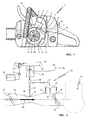
- FIG. 1 shown implement 1 is designed as a motor chain saw.
- the implement 1 could also be a cut-off grinder, a blower, a brushcutter or the like portable hand-held implement.
- an internal combustion engine 14 which has a cylinder 3 with a piston 4 moved up and down, which drives a crankshaft 6 via a connecting rod 5.
- the formed in the cylinder 3, bounded by the piston 4 combustion chamber 7 is associated with a spark plug 8, which serves to ignite a compressed in the combustion chamber 7 mixture.
- a fan 12 rotates, on the circumference 10 at least one permanent magnet is arranged.
- the permanent magnet cooperates with a yoke 11 of an ignition generator 9, which comprises an ignition control unit 13.
- the ignition control unit 13 is connected via an ignition cable 15 with the spark plug 8 and triggers a function of the rotational position of the crankshaft 6 and thus the stroke position of the piston 4 a spark for combustion of a sucked into the combustion chamber 7 fuel / air mixture.
- the fuel / air mixture is - as in Fig. 2 schematically illustrated - formed in an intake passage 20, to which a Venturiabites 21 is provided, through which the internal combustion engine 14 flowing combustion air (arrow 16) generates a negative pressure to suck via a main nozzle path 22 of the fuel system fuel.
- the fuel is supplied from a tank 23 via a Kraftstoffvor suitmpe 24 and a control valve 25 a control chamber 26.
- the control valve 25 is pressure-controlled and always opens when, due to the outflow of fuel, the control diaphragm 27 moves in the direction of the control chamber 26.
- the fuel channel 28 from the control chamber 26 to the main nozzle path 22 is controlled by an electrically operated fuel valve 30, which is electrically controlled by the ignition control unit 13 via a valve cable 29.
- the fuel channel 28 branches after the fuel valve 30 into the main nozzle path 22 and the idling path 32, which feeds via an idling chamber 31 and a plurality of idling nozzles 34, 35 and 36 opening into the intake passage 20 in the swiveling range of the throttle valve 33.
- a choke flap 37 located upstream of the venturi section 21 is closed, so that the negative pressure in the intake duct 20 is increased at the start.
- the increased negative pressure leads - is the fuel valve 30 open - to increased fuel flow through the main nozzle 39 of the main nozzle path 22 and the idling nozzles 34, 35 and 36 of the Leerlauspfades 32 in the intake passage 20.
- the internal combustion engine 14 is enriched for the start mixture fed (rich mixture).
- the electrical power supply of the ignition control unit 13, the spark plug 8 and the fuel valve 30 is effected by the in Fig. 3 Ignition generator 9 shown schematically, which consists of two with the crankshaft 6 rotating permanent magnets 17 and 18 and an associated yoke 11.
- the permanent magnets 17 and 18 are arranged on the circumference of the fan wheel 12 and cooperate with the yoke 11, which is on his Legs carries not shown coils.
- the yoke 11, the coils and the electronic circuit for controlling the fuel valve 30 and the spark plug 8 are encapsulated in a common unit to the ignition control unit 13.
- a preferably integrated in the ignition control unit 13 microprocessor 19 controls the ignition on the one hand and the opening duration of the fuel valve 30 on the other.
- the fuel valve 30 is a normally open valve as shown in FIG DE 102 42 816 A1 is described, the disclosure of which is part of the present application.
- the electrical energy generated at the beginning of the rotation of the crankshaft 6 in the direction of rotation 40 is first applied to the fuel valve 30, so that this - normally open - valve is initially closed.
- a voltage U is applied, wherein the voltage U V at the fuel valve 30 by a time factor .DELTA.t before the first ignition is so before the control unit 13 triggers a spark Z (diagram of the ignition ZZP) on the spark plug 8.
- the overall system is designed such that only the ignition generator 9 generates the energy necessary for the operation of the electrical consumers such as the spark plug 10, the fuel valve 30 and the microprocessor 19.
- the sequence is approximately such that with the onset of rotation of the crankshaft 6 and a first Vorbeidrenhen a permanent magnet 17 or 18 on the yoke 11 of the ignition generator 9, first the power supply of the control unit 13 made and thus the microprocessor of the control unit 13 is woken up so that it works and his Can fulfill control tasks.
- the ignition generator 9 is designed such that a first voltage wave is generated - by the first permanent magnet 17 - before a top dead center OT of the piston 4 and a second voltage wave through the permanent magnet 18 before a bottom dead center UT of the piston 4. This ensures that, after one revolution, sufficient energy is available to close the fuel valve 30. In this case, regardless of the operating temperature of the internal combustion engine 14 at each start of the engine 14 with the onset of rotation of the crankshaft 6, only the fuel valve 30 is energized before a spark Z is triggered.
- the fuel valve can be provided to keep the fuel valve closed over several crankshaft revolutions, preferably over two to six crankshaft revolutions, to ensure in this way that no superfatting of the starting mixture - especially at hot start - can occur.
- the valve is expediently kept completely closed over three crankshaft revolutions. It may be appropriate to trigger a spark in spite of the closed fuel valve in order to burn any residual mixture present in the combustion chamber.
- the control unit 13 After the fixed predetermined prioritized control of the fuel valve and one or more crankshaft revolutions of the microprocessor of the control unit is ready for operation and now takes over the control of the opening times of the fuel valve in response to one or more current operating parameters such. As the temperature, the rotational speed, the opening position of the throttle valve or the like. Accordingly, the closing duration of the fuel valve is then adjusted or varied, as in Fig. 4 below at the closing times shown on the right.
- the control unit 13 has taken over the control of the fuel valve; the fixed prioritization of the fuel valve according to the invention in the power supply in the start case is canceled.
- the field 62 branches via the branch "YES" to a delay z, ie, the fuel valve is advantageously kept open during the starting process for one or more crankshaft revolutions. So can the internal combustion engine sufficient Provided fuel / oil mixture and ensure adequate lubrication within the engine.
- Detecting a high friction state is also beneficial when fuel delivery is limited due to air or vapor bubbles in the fuel system. Limited or interrupted fuel delivery may also result in a high friction condition in the internal combustion engine. It may be advantageous, even in this state, to delay the signal for closing the electric fuel valve in order to support the fuel delivery.
- the principle for determining the reduced lubrication is carried out according to the flowchart in Fig. 5 ,
Landscapes
- Engineering & Computer Science (AREA)
- Chemical & Material Sciences (AREA)
- Combustion & Propulsion (AREA)
- Mechanical Engineering (AREA)
- General Engineering & Computer Science (AREA)
- Signal Processing (AREA)
- Theoretical Computer Science (AREA)
- Ignition Installations For Internal Combustion Engines (AREA)
- Electrical Control Of Air Or Fuel Supplied To Internal-Combustion Engine (AREA)
- Electrical Control Of Ignition Timing (AREA)
- Fuel-Injection Apparatus (AREA)
- Control Of Vehicle Engines Or Engines For Specific Uses (AREA)
Applications Claiming Priority (1)
| Application Number | Priority Date | Filing Date | Title |
|---|---|---|---|
| DE102013013628.8A DE102013013628B4 (de) | 2013-08-16 | 2013-08-16 | Verfahren zum Starten eines Verbrennungsmotors mit einer Startvorrichtung |
Publications (2)
| Publication Number | Publication Date |
|---|---|
| EP2848800A1 true EP2848800A1 (fr) | 2015-03-18 |
| EP2848800B1 EP2848800B1 (fr) | 2024-05-29 |
Family
ID=51292782
Family Applications (1)
| Application Number | Title | Priority Date | Filing Date |
|---|---|---|---|
| EP14002709.5A Active EP2848800B1 (fr) | 2013-08-16 | 2014-08-02 | Procédé destiné au démarrage d'un moteur à combustion interne doté d'un dispositif de démarrage |
Country Status (5)
| Country | Link |
|---|---|
| US (1) | US20150047593A1 (fr) |
| EP (1) | EP2848800B1 (fr) |
| JP (1) | JP2015036552A (fr) |
| CN (1) | CN104389711B (fr) |
| DE (1) | DE102013013628B4 (fr) |
Cited By (1)
| Publication number | Priority date | Publication date | Assignee | Title |
|---|---|---|---|---|
| EP3181856A3 (fr) * | 2015-12-15 | 2017-07-05 | Andreas Stihl AG & Co. KG | Appareil de travail manuel comprenant un dispositif de commande |
Families Citing this family (4)
| Publication number | Priority date | Publication date | Assignee | Title |
|---|---|---|---|---|
| US10800065B2 (en) * | 2015-12-15 | 2020-10-13 | Andreas Stihl Ag & Co. Kg | Hand-guided power tool with a control device |
| US10794351B2 (en) | 2016-08-10 | 2020-10-06 | Andreas Stihl Ag & Co. Kg | Starter device for an internal combustion engine and backpack power tool with an internal combustion engine and with a starter device for the internal combustion engine |
| DE102018002964A1 (de) | 2017-09-15 | 2019-03-21 | Andreas Stihl Ag & Co. Kg | Handgeführtes Arbeitsgerät |
| JP7409914B2 (ja) * | 2020-03-11 | 2024-01-09 | 株式会社やまびこ | エンジンを備えた携帯作業機 |
Citations (7)
| Publication number | Priority date | Publication date | Assignee | Title |
|---|---|---|---|---|
| US5419291A (en) * | 1992-06-16 | 1995-05-30 | Honda Giken Kogyo Kabushiki Kaisha | Electronic fuel injection system without battery for internal combustion engine |
| US20040025839A1 (en) * | 2002-08-09 | 2004-02-12 | Kazuyoshi Kashibata | Fuel injection and ignition system for internal combustion engine |
| DE10242816A1 (de) | 2002-09-14 | 2004-03-25 | Andreas Stihl Ag & Co | Elektromagnetisches Ventil |
| DE102005019762A1 (de) * | 2005-04-28 | 2006-11-02 | Andreas Stihl Ag & Co. Kg | Verfahren zur Steuerung eines elektromagnetischen Ventils in einem Kraftstoffsystem |
| EP1887204A1 (fr) * | 2006-08-01 | 2008-02-13 | Keihin Corporation | Dispositif électronique de commande d'injection de carburant |
| EP2031218A2 (fr) * | 2007-08-29 | 2009-03-04 | Keihin Corporation | Appareil de contrôle pour moteur à combustion interne |
| DE102009040321A1 (de) * | 2009-09-05 | 2011-03-10 | Andreas Stihl Ag & Co. Kg | Verfahren zum Betrieb eines Verbrennungsmotors |
Family Cites Families (9)
| Publication number | Priority date | Publication date | Assignee | Title |
|---|---|---|---|---|
| JP2503960B2 (ja) * | 1986-02-28 | 1996-06-05 | スズキ株式会社 | 燃料噴射制御装置 |
| JP2757566B2 (ja) * | 1990-12-28 | 1998-05-25 | 国産電機株式会社 | 内燃機関用燃料噴射装置 |
| JP3086335B2 (ja) * | 1992-06-16 | 2000-09-11 | 本田技研工業株式会社 | エンジンのバッテリレス電子燃料噴射制御装置 |
| JP3361422B2 (ja) * | 1995-12-15 | 2003-01-07 | 日本特殊陶業株式会社 | エンジン始動制御方法及び装置 |
| US6868832B2 (en) * | 2003-07-09 | 2005-03-22 | Honda Motor Co., Ltd. | Electronic controlled fuel injection apparatus of internal combustion engine |
| DE10335345B4 (de) * | 2003-08-01 | 2013-04-18 | Andreas Stihl Ag & Co. Kg | Verfahren zum Betrieb einer Vergaseranordnung für einen Verbrennungsmotor und Vergaseranordnung zu dessen Durchführung |
| JP4173502B2 (ja) * | 2005-08-05 | 2008-10-29 | 株式会社ケーヒン | 電子燃料噴射制御装置 |
| DE102005038198B4 (de) * | 2005-08-12 | 2021-10-07 | Andreas Stihl Ag & Co. Kg | Zündschaltung mit einem energiereichen Funken für einen Verbrennungsmotor |
| DE102009053047A1 (de) | 2009-11-16 | 2011-05-19 | Andreas Stihl Ag & Co. Kg | Verfahren zum Betrieb eines Verbrennungsmotors |
-
2013
- 2013-08-16 DE DE102013013628.8A patent/DE102013013628B4/de active Active
-
2014
- 2014-08-02 EP EP14002709.5A patent/EP2848800B1/fr active Active
- 2014-08-15 CN CN201410401901.1A patent/CN104389711B/zh active Active
- 2014-08-15 JP JP2014165429A patent/JP2015036552A/ja active Pending
- 2014-08-18 US US14/462,155 patent/US20150047593A1/en not_active Abandoned
Patent Citations (7)
| Publication number | Priority date | Publication date | Assignee | Title |
|---|---|---|---|---|
| US5419291A (en) * | 1992-06-16 | 1995-05-30 | Honda Giken Kogyo Kabushiki Kaisha | Electronic fuel injection system without battery for internal combustion engine |
| US20040025839A1 (en) * | 2002-08-09 | 2004-02-12 | Kazuyoshi Kashibata | Fuel injection and ignition system for internal combustion engine |
| DE10242816A1 (de) | 2002-09-14 | 2004-03-25 | Andreas Stihl Ag & Co | Elektromagnetisches Ventil |
| DE102005019762A1 (de) * | 2005-04-28 | 2006-11-02 | Andreas Stihl Ag & Co. Kg | Verfahren zur Steuerung eines elektromagnetischen Ventils in einem Kraftstoffsystem |
| EP1887204A1 (fr) * | 2006-08-01 | 2008-02-13 | Keihin Corporation | Dispositif électronique de commande d'injection de carburant |
| EP2031218A2 (fr) * | 2007-08-29 | 2009-03-04 | Keihin Corporation | Appareil de contrôle pour moteur à combustion interne |
| DE102009040321A1 (de) * | 2009-09-05 | 2011-03-10 | Andreas Stihl Ag & Co. Kg | Verfahren zum Betrieb eines Verbrennungsmotors |
Cited By (2)
| Publication number | Priority date | Publication date | Assignee | Title |
|---|---|---|---|---|
| EP3181856A3 (fr) * | 2015-12-15 | 2017-07-05 | Andreas Stihl AG & Co. KG | Appareil de travail manuel comprenant un dispositif de commande |
| US10322519B2 (en) | 2015-12-15 | 2019-06-18 | Andreas Stihl Ag & Co. Kg | Hand-guided power tool with a control device |
Also Published As
| Publication number | Publication date |
|---|---|
| CN104389711A (zh) | 2015-03-04 |
| DE102013013628A1 (de) | 2015-02-19 |
| EP2848800B1 (fr) | 2024-05-29 |
| US20150047593A1 (en) | 2015-02-19 |
| CN104389711B (zh) | 2018-07-03 |
| JP2015036552A (ja) | 2015-02-23 |
| DE102013013628B4 (de) | 2022-11-10 |
Similar Documents
| Publication | Publication Date | Title |
|---|---|---|
| EP1413727B1 (fr) | Méthode pour l'arrêt d'un moteur à combustion interne et moteur à combustion interne pour la mise en oeuvre de cette méthode | |
| DE102007031396B4 (de) | Verfahren zum Betrieb eines Zweitaktmotors | |
| DE102012002225B4 (de) | Handgeführtes Arbeitsgerät | |
| DE10335345B4 (de) | Verfahren zum Betrieb einer Vergaseranordnung für einen Verbrennungsmotor und Vergaseranordnung zu dessen Durchführung | |
| EP2848800B1 (fr) | Procédé destiné au démarrage d'un moteur à combustion interne doté d'un dispositif de démarrage | |
| EP2891785B1 (fr) | Procédé de fonctionnement d'un outillage portatif doté d'un moteur à combustion interne | |
| EP2746569B1 (fr) | Procédé de fonctionnement d'un moteur à combustion interne d'un outillage portatif | |
| DE102009053236A1 (de) | Handgeführtes Arbeitsgerät mit einem luftgekühlten Verbrennungsmotor | |
| EP2826982B1 (fr) | Procédé destiné au fonctionnement d'un moteur à combustion interne | |
| DE102008019088A1 (de) | Verfahren zum Betrieb eines Verbrennungsmotors | |
| DE1918382A1 (de) | Einrichtung an Brennkraftmaschinen zum Verhindern des Ausstroemens von Brennstoff aus dem Gemischbildungssystem in die Atmosphaere | |
| EP2787215B1 (fr) | Procédé destiné au fonctionnement d'un moteur à combustion interne | |
| DE3435824A1 (de) | Brennstoffeinspritzpumpe fuer dieselbrennkraftmaschinen | |
| EP2270325B1 (fr) | Procédé pour le fonctionnement d'un moteur à combustion interne | |
| DE102005019762B4 (de) | Verfahren zur Steuerung eines elektromagnetischen Ventils in einem Kraftstoffsystem | |
| DE2542619A1 (de) | Vorrichtung zum steuern der kraftstoffzufuhr zu einem verbrennungsmotor eines kraftfahrzeuges | |
| DE102009025195A1 (de) | Verfahren zum Betrieb eines Verbrennungsmotors | |
| DE10301191B4 (de) | Verfahren und Vorrichtung zum Betrieb einer Brennkraftmaschine | |
| EP3144521A2 (fr) | Procede de fonctionnement d'un appareil de travail comprenant un moteur a combustion | |
| DE102011008737B4 (de) | Verbrennungsmotor, Diagnosegerät für einen Verbrennungsmotor und Verfahren zur Einstellung eines Verbrennungsmotors | |
| DE102005002275A1 (de) | Verfahren zum Betrieb eines Einzylinder-Zweitaktmotors | |
| EP3660285B1 (fr) | À lubrificationmoteur à quatre temps lubrifié par mélange, appareil de travail guidé à la main à l'aide d'un moteur à quatre temps et procédé de fonctionnement d'un moteur à quatre temps lubrifié par mélange | |
| DE112011105943B4 (de) | Kraftmaschine und Abschaltverfahren für eine Kraftmaschine | |
| DE1186266B (de) | Vorrichtung zur Erzielung eines gleichmaessigen Leerlaufs einer mehrzylindrigen Zweitaktbrennkraftmaschine, vorzugsweise Vergasermaschine | |
| DE4236007B4 (de) | Verfahren und Vorrichtung zum Starten eines Ottomotors |
Legal Events
| Date | Code | Title | Description |
|---|---|---|---|
| PUAI | Public reference made under article 153(3) epc to a published international application that has entered the european phase |
Free format text: ORIGINAL CODE: 0009012 |
|
| 17P | Request for examination filed |
Effective date: 20140802 |
|
| AK | Designated contracting states |
Kind code of ref document: A1 Designated state(s): AL AT BE BG CH CY CZ DE DK EE ES FI FR GB GR HR HU IE IS IT LI LT LU LV MC MK MT NL NO PL PT RO RS SE SI SK SM TR |
|
| AX | Request for extension of the european patent |
Extension state: BA ME |
|
| R17P | Request for examination filed (corrected) |
Effective date: 20150918 |
|
| RBV | Designated contracting states (corrected) |
Designated state(s): AL AT BE BG CH CY CZ DE DK EE ES FI FR GB GR HR HU IE IS IT LI LT LU LV MC MK MT NL NO PL PT RO RS SE SI SK SM TR |
|
| STAA | Information on the status of an ep patent application or granted ep patent |
Free format text: STATUS: EXAMINATION IS IN PROGRESS |
|
| 17Q | First examination report despatched |
Effective date: 20210512 |
|
| RIC1 | Information provided on ipc code assigned before grant |
Ipc: F02B 75/02 20060101ALN20231108BHEP Ipc: F02D 39/04 20060101ALN20231108BHEP Ipc: F02D 41/30 20060101ALN20231108BHEP Ipc: F02P 5/155 20060101ALI20231108BHEP Ipc: F02M 3/02 20060101ALI20231108BHEP Ipc: F02M 1/02 20060101ALI20231108BHEP Ipc: F02M 3/05 20060101ALI20231108BHEP Ipc: F02M 69/46 20060101ALI20231108BHEP Ipc: F02M 69/34 20060101ALI20231108BHEP Ipc: F02D 41/20 20060101ALI20231108BHEP Ipc: F02D 41/06 20060101ALI20231108BHEP Ipc: F02B 63/02 20060101ALI20231108BHEP Ipc: F02P 1/00 20060101ALI20231108BHEP Ipc: F02P 5/15 20060101ALI20231108BHEP Ipc: F02N 3/02 20060101AFI20231108BHEP |
|
| GRAP | Despatch of communication of intention to grant a patent |
Free format text: ORIGINAL CODE: EPIDOSNIGR1 |
|
| STAA | Information on the status of an ep patent application or granted ep patent |
Free format text: STATUS: GRANT OF PATENT IS INTENDED |
|
| RIC1 | Information provided on ipc code assigned before grant |
Ipc: F02B 75/02 20060101ALN20231205BHEP Ipc: F02D 39/04 20060101ALN20231205BHEP Ipc: F02D 41/30 20060101ALN20231205BHEP Ipc: F02P 5/155 20060101ALI20231205BHEP Ipc: F02M 3/02 20060101ALI20231205BHEP Ipc: F02M 1/02 20060101ALI20231205BHEP Ipc: F02M 3/05 20060101ALI20231205BHEP Ipc: F02M 69/46 20060101ALI20231205BHEP Ipc: F02M 69/34 20060101ALI20231205BHEP Ipc: F02D 41/20 20060101ALI20231205BHEP Ipc: F02D 41/06 20060101ALI20231205BHEP Ipc: F02B 63/02 20060101ALI20231205BHEP Ipc: F02P 1/00 20060101ALI20231205BHEP Ipc: F02P 5/15 20060101ALI20231205BHEP Ipc: F02N 3/02 20060101AFI20231205BHEP |
|
| INTG | Intention to grant announced |
Effective date: 20240108 |
|
| GRAS | Grant fee paid |
Free format text: ORIGINAL CODE: EPIDOSNIGR3 |
|
| GRAA | (expected) grant |
Free format text: ORIGINAL CODE: 0009210 |
|
| STAA | Information on the status of an ep patent application or granted ep patent |
Free format text: STATUS: THE PATENT HAS BEEN GRANTED |
|
| RBV | Designated contracting states (corrected) |
Designated state(s): AL AT BE BG CH CY CZ DK EE ES FI FR GB GR HR HU IE IS IT LI LT LU LV MC MK MT NL NO PL PT RO RS SE SI SK SM TR |
|
| AK | Designated contracting states |
Kind code of ref document: B1 Designated state(s): AL AT BE BG CH CY CZ DK EE ES FI FR GB GR HR HU IE IS IT LI LT LU LV MC MK MT NL NO PL PT RO RS SE SI SK SM TR |
|
| REG | Reference to a national code |
Ref country code: GB Ref legal event code: FG4D Free format text: NOT ENGLISH |
|
| REG | Reference to a national code |
Ref country code: CH Ref legal event code: EP |
|
| REG | Reference to a national code |
Ref country code: IE Ref legal event code: FG4D Free format text: LANGUAGE OF EP DOCUMENT: GERMAN |
|
| REG | Reference to a national code |
Ref country code: LT Ref legal event code: MG9D |
|
| REG | Reference to a national code |
Ref country code: NL Ref legal event code: MP Effective date: 20240529 |
|
| PG25 | Lapsed in a contracting state [announced via postgrant information from national office to epo] |
Ref country code: IS Free format text: LAPSE BECAUSE OF FAILURE TO SUBMIT A TRANSLATION OF THE DESCRIPTION OR TO PAY THE FEE WITHIN THE PRESCRIBED TIME-LIMIT Effective date: 20240929 |
|
| PG25 | Lapsed in a contracting state [announced via postgrant information from national office to epo] |
Ref country code: BG Free format text: LAPSE BECAUSE OF FAILURE TO SUBMIT A TRANSLATION OF THE DESCRIPTION OR TO PAY THE FEE WITHIN THE PRESCRIBED TIME-LIMIT Effective date: 20240529 |
|
| PG25 | Lapsed in a contracting state [announced via postgrant information from national office to epo] |
Ref country code: FI Free format text: LAPSE BECAUSE OF FAILURE TO SUBMIT A TRANSLATION OF THE DESCRIPTION OR TO PAY THE FEE WITHIN THE PRESCRIBED TIME-LIMIT Effective date: 20240529 Ref country code: HR Free format text: LAPSE BECAUSE OF FAILURE TO SUBMIT A TRANSLATION OF THE DESCRIPTION OR TO PAY THE FEE WITHIN THE PRESCRIBED TIME-LIMIT Effective date: 20240529 |
|
| PG25 | Lapsed in a contracting state [announced via postgrant information from national office to epo] |
Ref country code: GR Free format text: LAPSE BECAUSE OF FAILURE TO SUBMIT A TRANSLATION OF THE DESCRIPTION OR TO PAY THE FEE WITHIN THE PRESCRIBED TIME-LIMIT Effective date: 20240830 |
|
| PG25 | Lapsed in a contracting state [announced via postgrant information from national office to epo] |
Ref country code: ES Free format text: LAPSE BECAUSE OF FAILURE TO SUBMIT A TRANSLATION OF THE DESCRIPTION OR TO PAY THE FEE WITHIN THE PRESCRIBED TIME-LIMIT Effective date: 20240529 |
|
| PG25 | Lapsed in a contracting state [announced via postgrant information from national office to epo] |
Ref country code: PL Free format text: LAPSE BECAUSE OF FAILURE TO SUBMIT A TRANSLATION OF THE DESCRIPTION OR TO PAY THE FEE WITHIN THE PRESCRIBED TIME-LIMIT Effective date: 20240529 |
|
| PG25 | Lapsed in a contracting state [announced via postgrant information from national office to epo] |
Ref country code: LV Free format text: LAPSE BECAUSE OF FAILURE TO SUBMIT A TRANSLATION OF THE DESCRIPTION OR TO PAY THE FEE WITHIN THE PRESCRIBED TIME-LIMIT Effective date: 20240529 |
|
| PG25 | Lapsed in a contracting state [announced via postgrant information from national office to epo] |
Ref country code: PL Free format text: LAPSE BECAUSE OF FAILURE TO SUBMIT A TRANSLATION OF THE DESCRIPTION OR TO PAY THE FEE WITHIN THE PRESCRIBED TIME-LIMIT Effective date: 20240529 Ref country code: NO Free format text: LAPSE BECAUSE OF FAILURE TO SUBMIT A TRANSLATION OF THE DESCRIPTION OR TO PAY THE FEE WITHIN THE PRESCRIBED TIME-LIMIT Effective date: 20240829 Ref country code: LV Free format text: LAPSE BECAUSE OF FAILURE TO SUBMIT A TRANSLATION OF THE DESCRIPTION OR TO PAY THE FEE WITHIN THE PRESCRIBED TIME-LIMIT Effective date: 20240529 Ref country code: IS Free format text: LAPSE BECAUSE OF FAILURE TO SUBMIT A TRANSLATION OF THE DESCRIPTION OR TO PAY THE FEE WITHIN THE PRESCRIBED TIME-LIMIT Effective date: 20240929 Ref country code: HR Free format text: LAPSE BECAUSE OF FAILURE TO SUBMIT A TRANSLATION OF THE DESCRIPTION OR TO PAY THE FEE WITHIN THE PRESCRIBED TIME-LIMIT Effective date: 20240529 Ref country code: GR Free format text: LAPSE BECAUSE OF FAILURE TO SUBMIT A TRANSLATION OF THE DESCRIPTION OR TO PAY THE FEE WITHIN THE PRESCRIBED TIME-LIMIT Effective date: 20240830 Ref country code: FI Free format text: LAPSE BECAUSE OF FAILURE TO SUBMIT A TRANSLATION OF THE DESCRIPTION OR TO PAY THE FEE WITHIN THE PRESCRIBED TIME-LIMIT Effective date: 20240529 Ref country code: ES Free format text: LAPSE BECAUSE OF FAILURE TO SUBMIT A TRANSLATION OF THE DESCRIPTION OR TO PAY THE FEE WITHIN THE PRESCRIBED TIME-LIMIT Effective date: 20240529 Ref country code: BG Free format text: LAPSE BECAUSE OF FAILURE TO SUBMIT A TRANSLATION OF THE DESCRIPTION OR TO PAY THE FEE WITHIN THE PRESCRIBED TIME-LIMIT Effective date: 20240529 Ref country code: RS Free format text: LAPSE BECAUSE OF FAILURE TO SUBMIT A TRANSLATION OF THE DESCRIPTION OR TO PAY THE FEE WITHIN THE PRESCRIBED TIME-LIMIT Effective date: 20240829 |
|
| PG25 | Lapsed in a contracting state [announced via postgrant information from national office to epo] |
Ref country code: NL Free format text: LAPSE BECAUSE OF FAILURE TO SUBMIT A TRANSLATION OF THE DESCRIPTION OR TO PAY THE FEE WITHIN THE PRESCRIBED TIME-LIMIT Effective date: 20240529 |
|
| PG25 | Lapsed in a contracting state [announced via postgrant information from national office to epo] |
Ref country code: NL Free format text: LAPSE BECAUSE OF FAILURE TO SUBMIT A TRANSLATION OF THE DESCRIPTION OR TO PAY THE FEE WITHIN THE PRESCRIBED TIME-LIMIT Effective date: 20240529 |
|
| PG25 | Lapsed in a contracting state [announced via postgrant information from national office to epo] |
Ref country code: DK Free format text: LAPSE BECAUSE OF FAILURE TO SUBMIT A TRANSLATION OF THE DESCRIPTION OR TO PAY THE FEE WITHIN THE PRESCRIBED TIME-LIMIT Effective date: 20240529 |
|
| PG25 | Lapsed in a contracting state [announced via postgrant information from national office to epo] |
Ref country code: EE Free format text: LAPSE BECAUSE OF FAILURE TO SUBMIT A TRANSLATION OF THE DESCRIPTION OR TO PAY THE FEE WITHIN THE PRESCRIBED TIME-LIMIT Effective date: 20240529 |
|
| PG25 | Lapsed in a contracting state [announced via postgrant information from national office to epo] |
Ref country code: CZ Free format text: LAPSE BECAUSE OF FAILURE TO SUBMIT A TRANSLATION OF THE DESCRIPTION OR TO PAY THE FEE WITHIN THE PRESCRIBED TIME-LIMIT Effective date: 20240529 |
|
| PG25 | Lapsed in a contracting state [announced via postgrant information from national office to epo] |
Ref country code: SK Free format text: LAPSE BECAUSE OF FAILURE TO SUBMIT A TRANSLATION OF THE DESCRIPTION OR TO PAY THE FEE WITHIN THE PRESCRIBED TIME-LIMIT Effective date: 20240529 Ref country code: RO Free format text: LAPSE BECAUSE OF FAILURE TO SUBMIT A TRANSLATION OF THE DESCRIPTION OR TO PAY THE FEE WITHIN THE PRESCRIBED TIME-LIMIT Effective date: 20240529 |
|
| PG25 | Lapsed in a contracting state [announced via postgrant information from national office to epo] |
Ref country code: SM Free format text: LAPSE BECAUSE OF FAILURE TO SUBMIT A TRANSLATION OF THE DESCRIPTION OR TO PAY THE FEE WITHIN THE PRESCRIBED TIME-LIMIT Effective date: 20240529 |
|
| PG25 | Lapsed in a contracting state [announced via postgrant information from national office to epo] |
Ref country code: SM Free format text: LAPSE BECAUSE OF FAILURE TO SUBMIT A TRANSLATION OF THE DESCRIPTION OR TO PAY THE FEE WITHIN THE PRESCRIBED TIME-LIMIT Effective date: 20240529 Ref country code: SK Free format text: LAPSE BECAUSE OF FAILURE TO SUBMIT A TRANSLATION OF THE DESCRIPTION OR TO PAY THE FEE WITHIN THE PRESCRIBED TIME-LIMIT Effective date: 20240529 Ref country code: RO Free format text: LAPSE BECAUSE OF FAILURE TO SUBMIT A TRANSLATION OF THE DESCRIPTION OR TO PAY THE FEE WITHIN THE PRESCRIBED TIME-LIMIT Effective date: 20240529 Ref country code: EE Free format text: LAPSE BECAUSE OF FAILURE TO SUBMIT A TRANSLATION OF THE DESCRIPTION OR TO PAY THE FEE WITHIN THE PRESCRIBED TIME-LIMIT Effective date: 20240529 Ref country code: DK Free format text: LAPSE BECAUSE OF FAILURE TO SUBMIT A TRANSLATION OF THE DESCRIPTION OR TO PAY THE FEE WITHIN THE PRESCRIBED TIME-LIMIT Effective date: 20240529 Ref country code: CZ Free format text: LAPSE BECAUSE OF FAILURE TO SUBMIT A TRANSLATION OF THE DESCRIPTION OR TO PAY THE FEE WITHIN THE PRESCRIBED TIME-LIMIT Effective date: 20240529 |
|
| PG25 | Lapsed in a contracting state [announced via postgrant information from national office to epo] |
Ref country code: IT Free format text: LAPSE BECAUSE OF FAILURE TO SUBMIT A TRANSLATION OF THE DESCRIPTION OR TO PAY THE FEE WITHIN THE PRESCRIBED TIME-LIMIT Effective date: 20240529 |
|
| REG | Reference to a national code |
Ref country code: CH Ref legal event code: PL |
|
| PLBE | No opposition filed within time limit |
Free format text: ORIGINAL CODE: 0009261 |
|
| STAA | Information on the status of an ep patent application or granted ep patent |
Free format text: STATUS: NO OPPOSITION FILED WITHIN TIME LIMIT |
|
| PG25 | Lapsed in a contracting state [announced via postgrant information from national office to epo] |
Ref country code: LU Free format text: LAPSE BECAUSE OF NON-PAYMENT OF DUE FEES Effective date: 20240802 |
|
| PG25 | Lapsed in a contracting state [announced via postgrant information from national office to epo] |
Ref country code: SI Free format text: LAPSE BECAUSE OF FAILURE TO SUBMIT A TRANSLATION OF THE DESCRIPTION OR TO PAY THE FEE WITHIN THE PRESCRIBED TIME-LIMIT Effective date: 20240529 Ref country code: MC Free format text: LAPSE BECAUSE OF FAILURE TO SUBMIT A TRANSLATION OF THE DESCRIPTION OR TO PAY THE FEE WITHIN THE PRESCRIBED TIME-LIMIT Effective date: 20240529 Ref country code: CH Free format text: LAPSE BECAUSE OF NON-PAYMENT OF DUE FEES Effective date: 20240831 |
|
| 26N | No opposition filed |
Effective date: 20250303 |
|
| REG | Reference to a national code |
Ref country code: BE Ref legal event code: MM Effective date: 20240831 |
|
| PG25 | Lapsed in a contracting state [announced via postgrant information from national office to epo] |
Ref country code: BE Free format text: LAPSE BECAUSE OF NON-PAYMENT OF DUE FEES Effective date: 20240831 |
|
| PG25 | Lapsed in a contracting state [announced via postgrant information from national office to epo] |
Ref country code: IE Free format text: LAPSE BECAUSE OF NON-PAYMENT OF DUE FEES Effective date: 20240802 |
|
| PG25 | Lapsed in a contracting state [announced via postgrant information from national office to epo] |
Ref country code: SE Free format text: LAPSE BECAUSE OF FAILURE TO SUBMIT A TRANSLATION OF THE DESCRIPTION OR TO PAY THE FEE WITHIN THE PRESCRIBED TIME-LIMIT Effective date: 20240529 |
|
| REG | Reference to a national code |
Ref country code: AT Ref legal event code: MM01 Ref document number: 1690841 Country of ref document: AT Kind code of ref document: T Effective date: 20240802 |
|
| PGFP | Annual fee paid to national office [announced via postgrant information from national office to epo] |
Ref country code: GB Payment date: 20250826 Year of fee payment: 12 |
|
| PG25 | Lapsed in a contracting state [announced via postgrant information from national office to epo] |
Ref country code: AT Free format text: LAPSE BECAUSE OF NON-PAYMENT OF DUE FEES Effective date: 20240802 |
|
| PGFP | Annual fee paid to national office [announced via postgrant information from national office to epo] |
Ref country code: FR Payment date: 20250825 Year of fee payment: 12 |
|
| PG25 | Lapsed in a contracting state [announced via postgrant information from national office to epo] |
Ref country code: PT Free format text: LAPSE BECAUSE OF NON-PAYMENT OF DUE FEES Effective date: 20240529 |
|
| PG25 | Lapsed in a contracting state [announced via postgrant information from national office to epo] |
Ref country code: CY Free format text: LAPSE BECAUSE OF FAILURE TO SUBMIT A TRANSLATION OF THE DESCRIPTION OR TO PAY THE FEE WITHIN THE PRESCRIBED TIME-LIMIT; INVALID AB INITIO Effective date: 20140802 |
|
| PG25 | Lapsed in a contracting state [announced via postgrant information from national office to epo] |
Ref country code: HU Free format text: LAPSE BECAUSE OF FAILURE TO SUBMIT A TRANSLATION OF THE DESCRIPTION OR TO PAY THE FEE WITHIN THE PRESCRIBED TIME-LIMIT; INVALID AB INITIO Effective date: 20140802 |