EP2848813A1 - Elektrische Pumpvorrichtung - Google Patents
Elektrische Pumpvorrichtung Download PDFInfo
- Publication number
- EP2848813A1 EP2848813A1 EP20140183880 EP14183880A EP2848813A1 EP 2848813 A1 EP2848813 A1 EP 2848813A1 EP 20140183880 EP20140183880 EP 20140183880 EP 14183880 A EP14183880 A EP 14183880A EP 2848813 A1 EP2848813 A1 EP 2848813A1
- Authority
- EP
- European Patent Office
- Prior art keywords
- ventilation
- main body
- cover main
- recessed portion
- ventilation passage
- Prior art date
- Legal status (The legal status is an assumption and is not a legal conclusion. Google has not performed a legal analysis and makes no representation as to the accuracy of the status listed.)
- Granted
Links
Images

Classifications
-
- F—MECHANICAL ENGINEERING; LIGHTING; HEATING; WEAPONS; BLASTING
- F04—POSITIVE - DISPLACEMENT MACHINES FOR LIQUIDS; PUMPS FOR LIQUIDS OR ELASTIC FLUIDS
- F04C—ROTARY-PISTON, OR OSCILLATING-PISTON, POSITIVE-DISPLACEMENT MACHINES FOR LIQUIDS; ROTARY-PISTON, OR OSCILLATING-PISTON, POSITIVE-DISPLACEMENT PUMPS
- F04C2/00—Rotary-piston machines or pumps
- F04C2/08—Rotary-piston machines or pumps of intermeshing-engagement type, i.e. with engagement of co-operating members similar to that of toothed gearing
- F04C2/082—Details specially related to intermeshing engagement type machines or pumps
- F04C2/086—Carter
-
- F—MECHANICAL ENGINEERING; LIGHTING; HEATING; WEAPONS; BLASTING
- F04—POSITIVE - DISPLACEMENT MACHINES FOR LIQUIDS; PUMPS FOR LIQUIDS OR ELASTIC FLUIDS
- F04D—NON-POSITIVE-DISPLACEMENT PUMPS
- F04D25/00—Pumping installations or systems
- F04D25/02—Units comprising pumps and their driving means
- F04D25/06—Units comprising pumps and their driving means the pump being electrically driven
-
- F—MECHANICAL ENGINEERING; LIGHTING; HEATING; WEAPONS; BLASTING
- F04—POSITIVE - DISPLACEMENT MACHINES FOR LIQUIDS; PUMPS FOR LIQUIDS OR ELASTIC FLUIDS
- F04C—ROTARY-PISTON, OR OSCILLATING-PISTON, POSITIVE-DISPLACEMENT MACHINES FOR LIQUIDS; ROTARY-PISTON, OR OSCILLATING-PISTON, POSITIVE-DISPLACEMENT PUMPS
- F04C15/00—Component parts, details or accessories of machines, pumps or pumping installations, not provided for in groups F04C2/00 - F04C14/00
- F04C15/0096—Heating; Cooling
-
- F—MECHANICAL ENGINEERING; LIGHTING; HEATING; WEAPONS; BLASTING
- F04—POSITIVE - DISPLACEMENT MACHINES FOR LIQUIDS; PUMPS FOR LIQUIDS OR ELASTIC FLUIDS
- F04D—NON-POSITIVE-DISPLACEMENT PUMPS
- F04D29/00—Details, component parts, or accessories
- F04D29/58—Cooling; Heating; Diminishing heat transfer
-
- F—MECHANICAL ENGINEERING; LIGHTING; HEATING; WEAPONS; BLASTING
- F04—POSITIVE - DISPLACEMENT MACHINES FOR LIQUIDS; PUMPS FOR LIQUIDS OR ELASTIC FLUIDS
- F04C—ROTARY-PISTON, OR OSCILLATING-PISTON, POSITIVE-DISPLACEMENT MACHINES FOR LIQUIDS; ROTARY-PISTON, OR OSCILLATING-PISTON, POSITIVE-DISPLACEMENT PUMPS
- F04C2/00—Rotary-piston machines or pumps
- F04C2/08—Rotary-piston machines or pumps of intermeshing-engagement type, i.e. with engagement of co-operating members similar to that of toothed gearing
- F04C2/10—Rotary-piston machines or pumps of intermeshing-engagement type, i.e. with engagement of co-operating members similar to that of toothed gearing of internal-axis type with the outer member having more teeth or tooth-equivalents, e.g. rollers, than the inner member
-
- F—MECHANICAL ENGINEERING; LIGHTING; HEATING; WEAPONS; BLASTING
- F04—POSITIVE - DISPLACEMENT MACHINES FOR LIQUIDS; PUMPS FOR LIQUIDS OR ELASTIC FLUIDS
- F04C—ROTARY-PISTON, OR OSCILLATING-PISTON, POSITIVE-DISPLACEMENT MACHINES FOR LIQUIDS; ROTARY-PISTON, OR OSCILLATING-PISTON, POSITIVE-DISPLACEMENT PUMPS
- F04C2240/00—Components
- F04C2240/30—Casings or housings
Definitions
- the present invention relates to an electric pump apparatus that includes a pump portion including a pump housing to which constituent members of a pump are fitted, and a motor portion including a motor housing to which constituent members of an electric motor for driving the pump are fitted.
- An object of the present invention is to provide an electric pump apparatus in which a cover main body and a ventilation cap body of a closing cover are integrally formed to reduce the number of components and man-hours required for assembly, thereby reducing the cost.
- an electric pump apparatus including a pump portion including a pump housing to which a constituent member of a pump is fitted; and a motor portion including a motor housing to which a constituent member of an electric motor for driving the pump is fitted, wherein one end of the motor housing is fitted to the pump housing in such a manner that a sealing member is interposed between the one end of the motor housing and the pump housing, wherein a closing cover is installed on an opening portion at the other end of the motor housing, wherein the closing cover integrally includes a cover main body, and a ventilation cap body that forms a ventilation passage for ventilation for an inside of the motor housing, wherein the ventilation cap body has a connecting portion that is integrally connected to the cover main body, and at least one ventilation passage hole that is disposed in the connecting portion to perpendicularly extend in a direction from an outer surface to an inner surface of the cover main body, and has a depth smaller than a plate thickness of the cover main body, wherein a ventilation recessed portion is formed at a
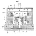
- an electric pump apparatus includes a pump portion 10 and a motor portion 30.
- the pump portion 10 includes a pump housing 11 to which constituent members of a pump are fitted.
- the motor portion 30 includes a motor housing 31 to which constituent members of an electric motor for driving the pump are fitted.
- an outer gear 16 and an inner gear 17 are provided in a pump chamber 15 formed between the pump housing 11 and and a pump plate 12 attached to one end of the pump housing 11.
- the outer gear 16 is a constituent member of the pump.
- the inner gear 17 has external teeth, and rotates with the external teeth meshing with internal teeth of the outer gear 16, thereby performing a pumping operation.
- a cylindrical bearing housing 18 protrudes from a central portion of an end face of the pump housing 11, the end face being located on a side opposite to the pump plate 12.
- a motor shaft 25 is rotatably supported in the bearing housing 18 via rolling bearings 20, 21.
- a gear shaft portion 26 is formed at one end of the motor shaft 25, and is fitted in a center portion of the inner gear 17 in such a manner that a torque can be transmitted.
- the motor housing 31 is made of a thermoplastic resin material, and has a cylindrical shape. One end of the motor housing 31 is fitted to the pump housing 11 in such a manner that a sealing member such as an O-ring 29 is interposed between the end of the motor housing 31 and the pump housing 11.
- a rotor 40 is fitted to a rotor shaft portion 27 in such a manner that torque can be transmitted.
- the rotor shaft portion 27 is the other end of the motor shaft 25.
- the rotor 40 has a disc portion 40a and a cylindrical portion 40b. A fitting hole is formed at the center of the disc portion 40a, and the rotor shaft portion 27 is fitted into the fitting hole in such a manner that torque can be transmitted.
- the cylindrical portion 40b extends integrally from an outer circumference of the disc portion 40a along an outer circumference of the bearing housing 18.
- a plurality of permanent magnets 41 is provided at predetermined intervals on an outer circumferential surface of the cylindrical portion 40b.
- a stator 32 is provided in the motor housing 31, and has a stator core 33 made of stacked steel sheets.
- a coil 35 is wound around the stator core 33 in an insulating state.
- the motor shaft 25, the rotor 40, the stator core 33, the stator 32, and the coil 35 are the constituent members of the motor.
- a board attachment portion 50 is formed in the vicinity of an opening at the other end of the motor housing 31.
- a control board 51 for controlling a motor is attached to the board attachment portion 50.
- a recessed annular groove 31 a is provided in an end face at the other end of the motor housing 31, and a closing cover 60, which will be described later, is fixed to the annular groove 31 a.
- the closing cover 60 is made of a thermoplastic resin material compatible with the resin material of which the motor housing 31 is formed.
- the closing cover 60 integrally includes a cover main body 60a and a ventilation cap body 71.
- the ventilation cap body 71 forms a ventilation passage 70 for ventilation for the inside of the motor housing 31.
- the cover main body 60a has a disc shape and has such a size as to close the opening portion at the other end of the motor housing 31.
- An annular protruding ring 61 is formed in a circumferential edge portion of a lower surface of the cover main body 60a, and is fitted into the annular groove 31 a in the end face at the other end of the motor housing 31.
- the annular protruding ring 61 is integrally joined to the annular groove 31a by spin welding, vibration welding, or the like, in a state where the annular protruding ring 61 is fitted into the annular groove 31 a. Accordingly, the closing cover 60 is integrally fixed to the motor housing 31.
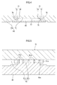
- the ventilation cap body 71 has a plurality of connecting portions 73 and a plurality of ventilation passage holes 72.
- the connecting portions 73 are arranged at intervals of a predetermined angle in a circumferential direction, and are integrally connected to the cover main body 60a.
- Each of the ventilation passage holes 72 is disposed between the connecting portions 73 to perpendicularly extend in a direction from an outer surface (an upper surface) to an inner surface (a lower surface) of the cover main body 60a, and has a depth smaller than the plate thickness of the cover main body 60a.
- the ventilation passage holes 72 are arranged in a radial manner.
- a ventilation recessed portion 77 is formed at a location that is positioned in the inner surface side of the cover main body 60a and that is positioned on an inner surface of the ventilation cap body 71.
- An inner circumferential wall surface 78 defining the ventilation recessed portion 77 is formed as a cylindrical surface having such an inside diameter that a deep side of each of the ventilation passage holes 72 is opened to the inner circumferential wall surface 78 defining the ventilation recessed portion 77 via an opening portion 74 to form the ventilation passage 70.
- each of the ventilation passage holes 72 has a slit shape that is elongated in a radial direction of the ventilation cap body 71.
- a slope surface 76 is formed in the vicinity of a radially inner end portion in such a manner that the position of the radially inner end portion is higher than that of a radially outer end portion.
- a ventilation filter 80 is installed on a portion around an inner opening portion of the ventilation recessed portion 77 so as to close the opening portion of the ventilation recessed portion 77.
- the ventilation filter 80 has a waterproof property and a property of allowing air ventilation.
- the closing cover 60 which is installed on the opening portion at the other end of the motor housing 31, integrally includes the cover main body 60a and the ventilation cap body 71.
- the ventilation cap body 71 forms the ventilation passage 70 for ventilation for the inside of the motor housing 31.
- the ventilation cap body 71 has the connecting portions 73, and the ventilation passage holes 72.
- the connecting portions 73 are integrally connected to the cover main body 60a.
- Each of the ventilation passage holes 72 is disposed between the connecting portions 73 to perpendicularly extend in the direction from the outer surface (the upper surface) to the inner surface (the lower surface) of the cover main body 60a, and has a depth smaller than the plate thickness of the cover main body 60a.
- each of the ventilation passage holes 72 is opened to the inner circumferential wall surface 78 defining the ventilation recessed portion 77 via the opening portion 74, the inner circumferential wall surface 78 being a cylindrical surface.
- the ventilation passage 70 is formed.
- the ventilation recessed portion 77 is formed at the location that is positioned in the inner surface side of the cover main body 60a and that is positioned on the inner surface of the ventilation cap body 71.
- a first molding die 90 and a second molding die 91 are used to form the closing cover 60 by injection molding.
- a protruding portion 90a for forming the ventilation recessed portion 77 is provided on a die surface of the first molding die 90.
- a plurality of column portions 91 a for forming the ventilation passage holes 72 is provided to protrude from a die surface of the second molding die 91.
- the cavity 92 has a cavity portion 92a corresponding to the cover main body 60a of the closing cover 60, and a cavity portion 92b corresponding to the ventilation cap body 71, the cavity portion 92a and the cavity portion 92b being continuous with each other.
- a melted thermoplastic resin material is injected into the cavity 92 formed between the first molding die 90 and the second molding die 91, and the cavity 92 is filled with the melted thermoplastic resin material.
- each of the ventilation passage holes 72 has a slit shape that is elongated in the radial direction of the ventilation cap body 71. Therefore, for example, when high-pressure water for vehicle washing or the like is sprayed onto the opening portions of the ventilation passage holes 72, a small amount of water is sprayed in a direction parallel to a hole direction of the ventilation passage holes 72, and a large amount of water collides with hole wall surfaces of the ventilation passage holes 72. That is, the high-pressure water sprayed onto the opening portions of the ventilation passage holes 72 can be prevented from directly reaching the opening portion 74 at the deep side of each of the ventilation passage holes 72, and the ventilation filter 80 can be protected from the high-pressure water.
- each of the ventilation passage holes 72 In the bottom face of each of the ventilation passage holes 72, the position of the radially inner end portion is higher than that of the radially outer end portion. Accordingly, even when water reaches the bottom face of each of the ventilation passage holes 72, the water is stopped by the slope surface 76 at the radially inner end portion of the bottom face of the ventilation passage hole 72, and the water can be prevented from intruding into a deeper region.
- the ventilation cap body 71 has the connecting portions 73 that are arranged at intervals of the predetermined angle in the circumferential direction, and are integrally connected to the cover main body 60a; and the ventilation passage holes 72, each of which is disposed between the connecting portions 73 to perpendicularly extend in the direction from the outer surface to the inner surface of the cover main body 60a, and has a depth smaller than the plate thickness of the cover main body 60a.
- the connecting portions 73 or the ventilation passage holes 72 may be disposed at any angular intervals.
- the number of connecting portions 73 or the ventilation passage holes 72 is not limited to a plural number, and at least one is required in the present invention.
- the ventilation recessed portion 77 which is formed at the location that is positioned in the inner surface side of the cover main body 60a and that is positioned on the inner surface of the ventilation cap body 71, may not be defined by a cylindrical surface. As long as the ventilation recessed portion 77 is formed in such a shape that the deep side of at least one ventilation passage hole 72 is opened to the inner wall surface defining the ventilation recessed portion 77, the ventilation recessed portion 77 may have any shape in the present invention.
- the cover main body and the ventilation cap body of the closing cover are integrally formed. Accordingly, it is possible to reduce the number of components, and man-hours required for assembly. Thus, the present invention has a great effect in cost reduction.
- a closing cover integrally includes a cover main body, and a ventilation cap body.
- the ventilation cap body has a connecting portion that is integrally connected to the cover main body, and at least one ventilation passage hole that is disposed in the connecting portion to perpendicularly extend, and has a depth smaller than a plate thickness of the cover main body.
- a ventilation recessed portion is formed at a location that is positioned on an inner surface of the ventilation cap body of the closing cover.
- An inner wall surface defining the ventilation recessed portion is formed in such a shape that a deep side of the ventilation passage hole is opened to the inner wall surface defining the ventilation recessed portion to form a ventilation passage.
- a ventilation filter is installed on an inner opening portion of the ventilation recessed portion.
Landscapes
- Engineering & Computer Science (AREA)
- Mechanical Engineering (AREA)
- General Engineering & Computer Science (AREA)
- Physics & Mathematics (AREA)
- Thermal Sciences (AREA)
- Motor Or Generator Frames (AREA)
- Rotary Pumps (AREA)
Applications Claiming Priority (1)
| Application Number | Priority Date | Filing Date | Title |
|---|---|---|---|
| JP2013189175A JP6248487B2 (ja) | 2013-09-12 | 2013-09-12 | 電動ポンプ装置 |
Publications (2)
| Publication Number | Publication Date |
|---|---|
| EP2848813A1 true EP2848813A1 (de) | 2015-03-18 |
| EP2848813B1 EP2848813B1 (de) | 2018-12-26 |
Family
ID=51564453
Family Applications (1)
| Application Number | Title | Priority Date | Filing Date |
|---|---|---|---|
| EP14183880.5A Active EP2848813B1 (de) | 2013-09-12 | 2014-09-08 | Elektrische Pumpvorrichtung |
Country Status (4)
| Country | Link |
|---|---|
| US (1) | US9771941B2 (de) |
| EP (1) | EP2848813B1 (de) |
| JP (1) | JP6248487B2 (de) |
| CN (1) | CN104454510B (de) |
Cited By (2)
| Publication number | Priority date | Publication date | Assignee | Title |
|---|---|---|---|---|
| WO2017140311A1 (de) * | 2016-02-15 | 2017-08-24 | Bühler Motor GmbH | Pumpenantrieb für die förderung eines reduktionsmittels für kfz-abgasanlagen, modulare motor- und pumpenfamilie zur bildung unterschiedlicher pumpenantriebe mit mehreren solcher elektromotoren |
| EP3348837A4 (de) * | 2015-09-11 | 2018-08-08 | Aisin Seiki Kabushiki Kaisha | Elektrische pumpe und verfahren zur herstellung davon |
Families Citing this family (4)
| Publication number | Priority date | Publication date | Assignee | Title |
|---|---|---|---|---|
| JP6950229B2 (ja) * | 2017-03-28 | 2021-10-13 | 株式会社アイシン | 防水カバー |
| KR102177671B1 (ko) * | 2019-08-22 | 2020-11-16 | 영신정공주식회사 | 전동 오일 펌프 |
| EP4579104A4 (de) * | 2022-11-30 | 2025-12-17 | Aisin Corp | Fahrzeugantriebsvorrichtung |
| CN116557288A (zh) * | 2023-05-15 | 2023-08-08 | 华域皮尔博格泵技术有限公司 | 一种无感电子油泵及系统 |
Citations (4)
| Publication number | Priority date | Publication date | Assignee | Title |
|---|---|---|---|---|
| US4721440A (en) * | 1987-02-13 | 1988-01-26 | Mechanical Technology Incorporated | Linear gas compressor |
| DE202004020959U1 (de) * | 2004-05-04 | 2006-07-20 | Ziegler, Günter | Bürstenloser Elektromotor zum Antrieb einer Vakuumpumpe in Luftfahrzeugen |
| JP2012110176A (ja) | 2010-11-19 | 2012-06-07 | Yamada Seisakusho Co Ltd | 電動ポンプ |
| JP2013087636A (ja) | 2011-10-14 | 2013-05-13 | Jtekt Corp | 電動オイルポンプ装置 |
Family Cites Families (10)
| Publication number | Priority date | Publication date | Assignee | Title |
|---|---|---|---|---|
| JP3795991B2 (ja) * | 1997-01-29 | 2006-07-12 | カルソニックカンセイ株式会社 | ファン駆動用モータの防水構造 |
| GB9807022D0 (en) * | 1998-04-02 | 1998-06-03 | Oldham Crompton Batteries Limi | Battery container |
| JP3589104B2 (ja) * | 1999-07-30 | 2004-11-17 | 日立電線株式会社 | 平面アンテナ装置及びそれに用いるアンテナカバー |
| AU2002300436B2 (en) * | 2002-02-08 | 2005-01-27 | Lg Electronics Inc. | Outer rotor type induction motor |
| CN101363441A (zh) * | 2008-09-10 | 2009-02-11 | 东莞市众隆电机电器制造有限公司 | 电动水泵 |
| DE102009010461A1 (de) * | 2009-02-13 | 2010-08-19 | Alfred Kärcher Gmbh & Co. Kg | Motorpumpeneinheit |
| CN201448263U (zh) * | 2009-07-31 | 2010-05-05 | 佛山市顺德区新生源电器有限公司 | 一种鼓风机 |
| JP2012026309A (ja) * | 2010-07-21 | 2012-02-09 | Jtekt Corp | 電動ポンプユニット |
| JP5927766B2 (ja) * | 2011-03-11 | 2016-06-01 | 株式会社ジェイテクト | 電動ポンプユニット |
| JP6056149B2 (ja) * | 2011-08-31 | 2017-01-11 | 株式会社ジェイテクト | 電動ポンプユニットおよびその製造方法 |
-
2013
- 2013-09-12 JP JP2013189175A patent/JP6248487B2/ja active Active
-
2014
- 2014-08-28 US US14/471,695 patent/US9771941B2/en active Active
- 2014-09-08 EP EP14183880.5A patent/EP2848813B1/de active Active
- 2014-09-10 CN CN201410456903.0A patent/CN104454510B/zh active Active
Patent Citations (4)
| Publication number | Priority date | Publication date | Assignee | Title |
|---|---|---|---|---|
| US4721440A (en) * | 1987-02-13 | 1988-01-26 | Mechanical Technology Incorporated | Linear gas compressor |
| DE202004020959U1 (de) * | 2004-05-04 | 2006-07-20 | Ziegler, Günter | Bürstenloser Elektromotor zum Antrieb einer Vakuumpumpe in Luftfahrzeugen |
| JP2012110176A (ja) | 2010-11-19 | 2012-06-07 | Yamada Seisakusho Co Ltd | 電動ポンプ |
| JP2013087636A (ja) | 2011-10-14 | 2013-05-13 | Jtekt Corp | 電動オイルポンプ装置 |
Cited By (3)
| Publication number | Priority date | Publication date | Assignee | Title |
|---|---|---|---|---|
| EP3348837A4 (de) * | 2015-09-11 | 2018-08-08 | Aisin Seiki Kabushiki Kaisha | Elektrische pumpe und verfahren zur herstellung davon |
| WO2017140311A1 (de) * | 2016-02-15 | 2017-08-24 | Bühler Motor GmbH | Pumpenantrieb für die förderung eines reduktionsmittels für kfz-abgasanlagen, modulare motor- und pumpenfamilie zur bildung unterschiedlicher pumpenantriebe mit mehreren solcher elektromotoren |
| US10920771B2 (en) | 2016-02-15 | 2021-02-16 | Bühler Motor GmbH | Pump drive for conveying a reducing agent for motor vehicle exhaust gas systems, modular motor and pump family for forming different pump drives with several such electric motors |
Also Published As
| Publication number | Publication date |
|---|---|
| CN104454510B (zh) | 2018-12-18 |
| US9771941B2 (en) | 2017-09-26 |
| JP2015056969A (ja) | 2015-03-23 |
| CN104454510A (zh) | 2015-03-25 |
| EP2848813B1 (de) | 2018-12-26 |
| JP6248487B2 (ja) | 2017-12-20 |
| US20150071796A1 (en) | 2015-03-12 |
Similar Documents
| Publication | Publication Date | Title |
|---|---|---|
| EP2848813B1 (de) | Elektrische Pumpvorrichtung | |
| CN105762977B (zh) | 电机驱动组件及其齿轮箱 | |
| JP6280771B2 (ja) | 送風機、モータおよびその製造方法 | |
| JP6597091B2 (ja) | 電動ポンプとその製造方法 | |
| US9966815B2 (en) | Stator including a bracket, electric motor including a stator, and method of producing an electric motor | |
| US10811927B2 (en) | Electric motor for use in pressurized fluid environment | |
| JP2015055201A (ja) | 電動ポンプユニット | |
| JP7078455B2 (ja) | 駆動装置 | |
| US20160211719A1 (en) | Rotor for brushless motor | |
| JP2017017798A (ja) | 電動機及びその製造方法 | |
| US8436502B2 (en) | Electric motor with sealing means | |
| JP6107401B2 (ja) | 電動機及びその製造方法 | |
| US20160201692A1 (en) | Fuel pump | |
| JP2007329995A (ja) | モータ | |
| JP2018159335A5 (de) | ||
| WO2020166531A1 (ja) | モータユニット | |
| JP6084858B2 (ja) | 電動ポンプ及び電動ポンプの組付方法 | |
| KR101855522B1 (ko) | 오일 누출 방지구조를 가지는 모터 | |
| JP2010063223A (ja) | 電動モータユニット | |
| JP5212147B2 (ja) | 電動ポンプユニット | |
| KR20190124741A (ko) | 전동기 | |
| JP5959088B2 (ja) | モータの冷却通路構造 | |
| CN222282934U (zh) | 一种电机端盖及其电机 | |
| JP6365203B2 (ja) | 電動ポンプ | |
| WO2020166541A1 (ja) | モータユニットおよびモータユニットの製造方法 |
Legal Events
| Date | Code | Title | Description |
|---|---|---|---|
| PUAI | Public reference made under article 153(3) epc to a published international application that has entered the european phase |
Free format text: ORIGINAL CODE: 0009012 |
|
| 17P | Request for examination filed |
Effective date: 20140908 |
|
| AK | Designated contracting states |
Kind code of ref document: A1 Designated state(s): AL AT BE BG CH CY CZ DE DK EE ES FI FR GB GR HR HU IE IS IT LI LT LU LV MC MK MT NL NO PL PT RO RS SE SI SK SM TR |
|
| AX | Request for extension of the european patent |
Extension state: BA ME |
|
| R17P | Request for examination filed (corrected) |
Effective date: 20150326 |
|
| STAA | Information on the status of an ep patent application or granted ep patent |
Free format text: STATUS: EXAMINATION IS IN PROGRESS |
|
| 17Q | First examination report despatched |
Effective date: 20180403 |
|
| GRAP | Despatch of communication of intention to grant a patent |
Free format text: ORIGINAL CODE: EPIDOSNIGR1 |
|
| STAA | Information on the status of an ep patent application or granted ep patent |
Free format text: STATUS: GRANT OF PATENT IS INTENDED |
|
| INTG | Intention to grant announced |
Effective date: 20180709 |
|
| GRAS | Grant fee paid |
Free format text: ORIGINAL CODE: EPIDOSNIGR3 |
|
| GRAA | (expected) grant |
Free format text: ORIGINAL CODE: 0009210 |
|
| STAA | Information on the status of an ep patent application or granted ep patent |
Free format text: STATUS: THE PATENT HAS BEEN GRANTED |
|
| AK | Designated contracting states |
Kind code of ref document: B1 Designated state(s): AL AT BE BG CH CY CZ DE DK EE ES FI FR GB GR HR HU IE IS IT LI LT LU LV MC MK MT NL NO PL PT RO RS SE SI SK SM TR |
|
| REG | Reference to a national code |
Ref country code: GB Ref legal event code: FG4D |
|
| REG | Reference to a national code |
Ref country code: CH Ref legal event code: EP |
|
| REG | Reference to a national code |
Ref country code: AT Ref legal event code: REF Ref document number: 1081798 Country of ref document: AT Kind code of ref document: T Effective date: 20190115 |
|
| REG | Reference to a national code |
Ref country code: DE Ref legal event code: R096 Ref document number: 602014038511 Country of ref document: DE |
|
| REG | Reference to a national code |
Ref country code: IE Ref legal event code: FG4D |
|
| PG25 | Lapsed in a contracting state [announced via postgrant information from national office to epo] |
Ref country code: FI Free format text: LAPSE BECAUSE OF FAILURE TO SUBMIT A TRANSLATION OF THE DESCRIPTION OR TO PAY THE FEE WITHIN THE PRESCRIBED TIME-LIMIT Effective date: 20181226 Ref country code: NO Free format text: LAPSE BECAUSE OF FAILURE TO SUBMIT A TRANSLATION OF THE DESCRIPTION OR TO PAY THE FEE WITHIN THE PRESCRIBED TIME-LIMIT Effective date: 20190326 Ref country code: LV Free format text: LAPSE BECAUSE OF FAILURE TO SUBMIT A TRANSLATION OF THE DESCRIPTION OR TO PAY THE FEE WITHIN THE PRESCRIBED TIME-LIMIT Effective date: 20181226 Ref country code: HR Free format text: LAPSE BECAUSE OF FAILURE TO SUBMIT A TRANSLATION OF THE DESCRIPTION OR TO PAY THE FEE WITHIN THE PRESCRIBED TIME-LIMIT Effective date: 20181226 Ref country code: LT Free format text: LAPSE BECAUSE OF FAILURE TO SUBMIT A TRANSLATION OF THE DESCRIPTION OR TO PAY THE FEE WITHIN THE PRESCRIBED TIME-LIMIT Effective date: 20181226 Ref country code: BG Free format text: LAPSE BECAUSE OF FAILURE TO SUBMIT A TRANSLATION OF THE DESCRIPTION OR TO PAY THE FEE WITHIN THE PRESCRIBED TIME-LIMIT Effective date: 20190326 |
|
| REG | Reference to a national code |
Ref country code: NL Ref legal event code: MP Effective date: 20181226 |
|
| REG | Reference to a national code |
Ref country code: LT Ref legal event code: MG4D |
|
| PG25 | Lapsed in a contracting state [announced via postgrant information from national office to epo] |
Ref country code: AL Free format text: LAPSE BECAUSE OF FAILURE TO SUBMIT A TRANSLATION OF THE DESCRIPTION OR TO PAY THE FEE WITHIN THE PRESCRIBED TIME-LIMIT Effective date: 20181226 Ref country code: RS Free format text: LAPSE BECAUSE OF FAILURE TO SUBMIT A TRANSLATION OF THE DESCRIPTION OR TO PAY THE FEE WITHIN THE PRESCRIBED TIME-LIMIT Effective date: 20181226 Ref country code: GR Free format text: LAPSE BECAUSE OF FAILURE TO SUBMIT A TRANSLATION OF THE DESCRIPTION OR TO PAY THE FEE WITHIN THE PRESCRIBED TIME-LIMIT Effective date: 20190327 Ref country code: SE Free format text: LAPSE BECAUSE OF FAILURE TO SUBMIT A TRANSLATION OF THE DESCRIPTION OR TO PAY THE FEE WITHIN THE PRESCRIBED TIME-LIMIT Effective date: 20181226 |
|
| REG | Reference to a national code |
Ref country code: AT Ref legal event code: MK05 Ref document number: 1081798 Country of ref document: AT Kind code of ref document: T Effective date: 20181226 |
|
| PG25 | Lapsed in a contracting state [announced via postgrant information from national office to epo] |
Ref country code: NL Free format text: LAPSE BECAUSE OF FAILURE TO SUBMIT A TRANSLATION OF THE DESCRIPTION OR TO PAY THE FEE WITHIN THE PRESCRIBED TIME-LIMIT Effective date: 20181226 |
|
| PG25 | Lapsed in a contracting state [announced via postgrant information from national office to epo] |
Ref country code: CZ Free format text: LAPSE BECAUSE OF FAILURE TO SUBMIT A TRANSLATION OF THE DESCRIPTION OR TO PAY THE FEE WITHIN THE PRESCRIBED TIME-LIMIT Effective date: 20181226 Ref country code: PL Free format text: LAPSE BECAUSE OF FAILURE TO SUBMIT A TRANSLATION OF THE DESCRIPTION OR TO PAY THE FEE WITHIN THE PRESCRIBED TIME-LIMIT Effective date: 20181226 Ref country code: ES Free format text: LAPSE BECAUSE OF FAILURE TO SUBMIT A TRANSLATION OF THE DESCRIPTION OR TO PAY THE FEE WITHIN THE PRESCRIBED TIME-LIMIT Effective date: 20181226 Ref country code: PT Free format text: LAPSE BECAUSE OF FAILURE TO SUBMIT A TRANSLATION OF THE DESCRIPTION OR TO PAY THE FEE WITHIN THE PRESCRIBED TIME-LIMIT Effective date: 20190426 Ref country code: IT Free format text: LAPSE BECAUSE OF FAILURE TO SUBMIT A TRANSLATION OF THE DESCRIPTION OR TO PAY THE FEE WITHIN THE PRESCRIBED TIME-LIMIT Effective date: 20181226 |
|
| PG25 | Lapsed in a contracting state [announced via postgrant information from national office to epo] |
Ref country code: SM Free format text: LAPSE BECAUSE OF FAILURE TO SUBMIT A TRANSLATION OF THE DESCRIPTION OR TO PAY THE FEE WITHIN THE PRESCRIBED TIME-LIMIT Effective date: 20181226 Ref country code: EE Free format text: LAPSE BECAUSE OF FAILURE TO SUBMIT A TRANSLATION OF THE DESCRIPTION OR TO PAY THE FEE WITHIN THE PRESCRIBED TIME-LIMIT Effective date: 20181226 Ref country code: RO Free format text: LAPSE BECAUSE OF FAILURE TO SUBMIT A TRANSLATION OF THE DESCRIPTION OR TO PAY THE FEE WITHIN THE PRESCRIBED TIME-LIMIT Effective date: 20181226 Ref country code: IS Free format text: LAPSE BECAUSE OF FAILURE TO SUBMIT A TRANSLATION OF THE DESCRIPTION OR TO PAY THE FEE WITHIN THE PRESCRIBED TIME-LIMIT Effective date: 20190426 Ref country code: SK Free format text: LAPSE BECAUSE OF FAILURE TO SUBMIT A TRANSLATION OF THE DESCRIPTION OR TO PAY THE FEE WITHIN THE PRESCRIBED TIME-LIMIT Effective date: 20181226 |
|
| REG | Reference to a national code |
Ref country code: DE Ref legal event code: R097 Ref document number: 602014038511 Country of ref document: DE |
|
| PG25 | Lapsed in a contracting state [announced via postgrant information from national office to epo] |
Ref country code: DK Free format text: LAPSE BECAUSE OF FAILURE TO SUBMIT A TRANSLATION OF THE DESCRIPTION OR TO PAY THE FEE WITHIN THE PRESCRIBED TIME-LIMIT Effective date: 20181226 Ref country code: AT Free format text: LAPSE BECAUSE OF FAILURE TO SUBMIT A TRANSLATION OF THE DESCRIPTION OR TO PAY THE FEE WITHIN THE PRESCRIBED TIME-LIMIT Effective date: 20181226 |
|
| PLBE | No opposition filed within time limit |
Free format text: ORIGINAL CODE: 0009261 |
|
| STAA | Information on the status of an ep patent application or granted ep patent |
Free format text: STATUS: NO OPPOSITION FILED WITHIN TIME LIMIT |
|
| 26N | No opposition filed |
Effective date: 20190927 |
|
| PG25 | Lapsed in a contracting state [announced via postgrant information from national office to epo] |
Ref country code: SI Free format text: LAPSE BECAUSE OF FAILURE TO SUBMIT A TRANSLATION OF THE DESCRIPTION OR TO PAY THE FEE WITHIN THE PRESCRIBED TIME-LIMIT Effective date: 20181226 |
|
| PG25 | Lapsed in a contracting state [announced via postgrant information from national office to epo] |
Ref country code: TR Free format text: LAPSE BECAUSE OF FAILURE TO SUBMIT A TRANSLATION OF THE DESCRIPTION OR TO PAY THE FEE WITHIN THE PRESCRIBED TIME-LIMIT Effective date: 20181226 |
|
| PG25 | Lapsed in a contracting state [announced via postgrant information from national office to epo] |
Ref country code: MC Free format text: LAPSE BECAUSE OF FAILURE TO SUBMIT A TRANSLATION OF THE DESCRIPTION OR TO PAY THE FEE WITHIN THE PRESCRIBED TIME-LIMIT Effective date: 20181226 |
|
| REG | Reference to a national code |
Ref country code: CH Ref legal event code: PL |
|
| PG25 | Lapsed in a contracting state [announced via postgrant information from national office to epo] |
Ref country code: LI Free format text: LAPSE BECAUSE OF NON-PAYMENT OF DUE FEES Effective date: 20190930 Ref country code: CH Free format text: LAPSE BECAUSE OF NON-PAYMENT OF DUE FEES Effective date: 20190930 Ref country code: LU Free format text: LAPSE BECAUSE OF NON-PAYMENT OF DUE FEES Effective date: 20190908 Ref country code: IE Free format text: LAPSE BECAUSE OF NON-PAYMENT OF DUE FEES Effective date: 20190908 |
|
| REG | Reference to a national code |
Ref country code: BE Ref legal event code: MM Effective date: 20190930 |
|
| PG25 | Lapsed in a contracting state [announced via postgrant information from national office to epo] |
Ref country code: BE Free format text: LAPSE BECAUSE OF NON-PAYMENT OF DUE FEES Effective date: 20190930 |
|
| GBPC | Gb: european patent ceased through non-payment of renewal fee |
Effective date: 20190908 |
|
| PG25 | Lapsed in a contracting state [announced via postgrant information from national office to epo] |
Ref country code: GB Free format text: LAPSE BECAUSE OF NON-PAYMENT OF DUE FEES Effective date: 20190908 |
|
| PG25 | Lapsed in a contracting state [announced via postgrant information from national office to epo] |
Ref country code: CY Free format text: LAPSE BECAUSE OF FAILURE TO SUBMIT A TRANSLATION OF THE DESCRIPTION OR TO PAY THE FEE WITHIN THE PRESCRIBED TIME-LIMIT Effective date: 20181226 |
|
| PG25 | Lapsed in a contracting state [announced via postgrant information from national office to epo] |
Ref country code: MT Free format text: LAPSE BECAUSE OF FAILURE TO SUBMIT A TRANSLATION OF THE DESCRIPTION OR TO PAY THE FEE WITHIN THE PRESCRIBED TIME-LIMIT Effective date: 20181226 Ref country code: HU Free format text: LAPSE BECAUSE OF FAILURE TO SUBMIT A TRANSLATION OF THE DESCRIPTION OR TO PAY THE FEE WITHIN THE PRESCRIBED TIME-LIMIT; INVALID AB INITIO Effective date: 20140908 |
|
| PGFP | Annual fee paid to national office [announced via postgrant information from national office to epo] |
Ref country code: FR Payment date: 20210812 Year of fee payment: 8 |
|
| PG25 | Lapsed in a contracting state [announced via postgrant information from national office to epo] |
Ref country code: MK Free format text: LAPSE BECAUSE OF FAILURE TO SUBMIT A TRANSLATION OF THE DESCRIPTION OR TO PAY THE FEE WITHIN THE PRESCRIBED TIME-LIMIT Effective date: 20181226 |
|
| PG25 | Lapsed in a contracting state [announced via postgrant information from national office to epo] |
Ref country code: FR Free format text: LAPSE BECAUSE OF NON-PAYMENT OF DUE FEES Effective date: 20220930 |
|
| PGFP | Annual fee paid to national office [announced via postgrant information from national office to epo] |
Ref country code: DE Payment date: 20250730 Year of fee payment: 12 |