EP2849012B1 - Système de commande, console d'opérateur et support de données mobiles pour machine-outil - Google Patents
Système de commande, console d'opérateur et support de données mobiles pour machine-outil Download PDFInfo
- Publication number
- EP2849012B1 EP2849012B1 EP13184341.9A EP13184341A EP2849012B1 EP 2849012 B1 EP2849012 B1 EP 2849012B1 EP 13184341 A EP13184341 A EP 13184341A EP 2849012 B1 EP2849012 B1 EP 2849012B1
- Authority
- EP
- European Patent Office
- Prior art keywords
- data carrier
- mobile data
- receiving slot
- receiving
- control device
- Prior art date
- Legal status (The legal status is an assumption and is not a legal conclusion. Google has not performed a legal analysis and makes no representation as to the accuracy of the status listed.)
- Not-in-force
Links
Images



Classifications
-
- G—PHYSICS
- G05—CONTROLLING; REGULATING
- G05B—CONTROL OR REGULATING SYSTEMS IN GENERAL; FUNCTIONAL ELEMENTS OF SUCH SYSTEMS; MONITORING OR TESTING ARRANGEMENTS FOR SUCH SYSTEMS OR ELEMENTS
- G05B19/00—Program-control systems
- G05B19/02—Program-control systems electric
- G05B19/18—Numerical control [NC], i.e. automatically operating machines, in particular machine tools, e.g. in a manufacturing environment, so as to execute positioning, movement or co-ordinated operations by means of program data in numerical form
- G05B19/402—Numerical control [NC], i.e. automatically operating machines, in particular machine tools, e.g. in a manufacturing environment, so as to execute positioning, movement or co-ordinated operations by means of program data in numerical form characterised by control arrangements for positioning, e.g. centring a tool relative to a hole in the workpiece, additional detection means to correct position
-
- G—PHYSICS
- G05—CONTROLLING; REGULATING
- G05B—CONTROL OR REGULATING SYSTEMS IN GENERAL; FUNCTIONAL ELEMENTS OF SUCH SYSTEMS; MONITORING OR TESTING ARRANGEMENTS FOR SUCH SYSTEMS OR ELEMENTS
- G05B19/00—Program-control systems
- G05B19/02—Program-control systems electric
- G05B19/18—Numerical control [NC], i.e. automatically operating machines, in particular machine tools, e.g. in a manufacturing environment, so as to execute positioning, movement or co-ordinated operations by means of program data in numerical form
- G05B19/401—Numerical control [NC], i.e. automatically operating machines, in particular machine tools, e.g. in a manufacturing environment, so as to execute positioning, movement or co-ordinated operations by means of program data in numerical form characterised by control arrangements for measuring, e.g. calibration and initialisation, measuring workpiece for machining purposes
-
- G—PHYSICS
- G05—CONTROLLING; REGULATING
- G05B—CONTROL OR REGULATING SYSTEMS IN GENERAL; FUNCTIONAL ELEMENTS OF SUCH SYSTEMS; MONITORING OR TESTING ARRANGEMENTS FOR SUCH SYSTEMS OR ELEMENTS
- G05B19/00—Program-control systems
- G05B19/02—Program-control systems electric
- G05B19/18—Numerical control [NC], i.e. automatically operating machines, in particular machine tools, e.g. in a manufacturing environment, so as to execute positioning, movement or co-ordinated operations by means of program data in numerical form
- G05B19/409—Numerical control [NC], i.e. automatically operating machines, in particular machine tools, e.g. in a manufacturing environment, so as to execute positioning, movement or co-ordinated operations by means of program data in numerical form characterised by using manual data input [MDI] or by using control panel, e.g. controlling functions with the panel; characterised by control panel details or by setting parameters
-
- G—PHYSICS
- G05—CONTROLLING; REGULATING
- G05B—CONTROL OR REGULATING SYSTEMS IN GENERAL; FUNCTIONAL ELEMENTS OF SUCH SYSTEMS; MONITORING OR TESTING ARRANGEMENTS FOR SUCH SYSTEMS OR ELEMENTS
- G05B2219/00—Program-control systems
- G05B2219/30—Nc systems
- G05B2219/36—Nc in input of data, input key till input tape
- G05B2219/36133—MMI, HMI: man machine interface, communication
-
- H—ELECTRICITY
- H01—ELECTRIC ELEMENTS
- H01R—ELECTRICALLY-CONDUCTIVE CONNECTIONS; STRUCTURAL ASSOCIATIONS OF A PLURALITY OF MUTUALLY-INSULATED ELECTRICAL CONNECTING ELEMENTS; COUPLING DEVICES; CURRENT COLLECTORS
- H01R13/00—Details of coupling devices of the kinds covered by groups H01R12/70 or H01R24/00 - H01R33/00
- H01R13/46—Bases; Cases
- H01R13/52—Dustproof, splashproof, drip-proof, waterproof, or flameproof cases
- H01R13/5227—Dustproof, splashproof, drip-proof, waterproof, or flameproof cases with evacuation of penetrating liquids
Definitions
- the present invention relates to a system for control of a numerically controlled machine tool by a user, comprising an operator console being operable by the user and a mobile data carrier, and to an operator console and a mobile data carrier for use in such system.
- DE 10 2007 041 768 A1 shows an access control device set up to control access by a user to a machine tool by use of a mobile data carrier which is communicably connectable to a control device of an operator console of a numerically controlled machine tool by means of a communication interface, for example, so that the control device can read identification data from a storage means of the mobile data carrier which uniquely identifies the particular user and allows to determine access rights of the user by the control device.
- EP 2 151 726 A2 describes a machine having a control computer for controlling spindles, a data carrier that is attached to the machine, and an interface for reading the carrier.
- the machine is programmable and/or controllable by a programming hand-held device.
- the control computer automatically controls the spindles, in an automatic operation.
- the machine is operated in the automatic operation only when the data carrier is operatively connected to the interface.
- the carrier is a memory card, a smart card, a universal serial bus stick or radio frequency identification transponder.
- DE 10 2008 008646 A1 describes a control having a processing unit i.e. CPU, a memory and a writing and reading device i.e. universal serial bus (USB) interface, for writing and reading machine data in/from a removable storage device i.e. flash memory such as USB stick.
- the machine data comprises machine parameter, drive parameter, files in a RAM file system, files in a user electrically EPROM, tool tables, system data and permanent single-parameter scaling (SPS) variables.
- SPS single-parameter scaling
- GB 2 233 170 A describes electrical connectors including a base (preferably formed of a plastics material) having an upright retaining wall.
- An electrically conductive bus plate has a base portion disposed adjacent a forward surface of the retaining wall so that a male terminal projects forwardly therefrom.
- a tubular housing is coupled to the base forwardly of the retaining wall via resilient tongue structures, and includes an opening through which the male terminal extends. When mounted to the base, a rear wall of the tubular housing will forcibly press the base portion of the male terminal against the retaining wall so as to rigidly hold the male terminal positionally within the tubular housing.
- a female plug body having female terminals may thus be inserted within the tubular housing so that the male terminal and female terminal are mated thereby establishing electrical communication with an external circuit, for example.
- EP 1 990 872 A1 describes an electric connector assembly, which comprises a plurality of male connectors each having a lock arm and a lock arm protecting member, and a female connector having a plurality of male connector accepting units.
- walls in a female housing between the adjoining male connector accepting units are positioned at their front ends on the deeper side than the fitting faces of the female housing.
- the fitting faces in the upper walls or the lower walls of the male connector accepting units are provided with recesses for accepting the lock arm protecting members of the male connectors.
- connection between the control device and the mobile data carrier can be efficiently and reliably established physically as well as with regard to efficiently and reliably enabling data exchange every time even in case of high number of connection attempts by different users by at the same time causing as low as possible wearing effects over long times.
- a system for control of a numerically controlled machine tool by a user comprises an operator console being operable by the user and a mobile data carrier.
- the operator console has a control device for control of the machine tool and a receiving member having a receiving slot for receiving the mobile data carrier, wherein the control device of the operator console has a first communication interface adapted to be communicably connected to a second communication interface of the mobile data carrier.
- the second communication interface includes a female connector socket and the first communication interface includes a male connector plug provided at an inner end face portion of the receiving slot for being plugged into the female connector socket of the mobile data when the mobile data carrier is received in the receiving slot.
- an advantageous connectability between the mobile data carrier and the control device of the operator console of the machine tool involving a connection in which the mobile data carrier as a physical male connection part can be inserted into the receiving slot of the control device of the operator console of the machine tool as a physical female connection part, wherein the communication connection is, however, established by the female connector socket of the mobile data carrier and the male connector plug of the control device of the operator console of the machine tool.
- the connector of the control device as a male connector plug can be reliably protected against damage by being embedded into and by being covered by the receiving slot, preferably not extending out of the receiving slot, and, on the other hand, the connector of the mobile data carrier can be reliably protected against damage by being realized as the female connector socket, which preferably does not extend out of a protective casing of the mobile data carrier.
- the communication connection can be efficiently and reliably established.
- the mobile data carrier may have an elongated casing which has an upper outer side and a lower outer side opposite to the upper outer side, and which has an insertion portion being formed at a first end of the mobile data carrier on the side of the female connector socket.
- the receiving slot may have an elongated shape having an upper inner side and a lower inner side opposite to the upper inner side.
- a cross-sectional shape of a receiving portion of the receiving slot is at least partially adapted to fit a cross-sectional shape of the insertion portion of the casing of the mobile data carrier, in particular such that the insertion portion of the mobile data carrier is insertable into the receiving portion of the receiving slot only such that the first outer side of the casing of the mobile data carrier faces the first inner side of the receiving slot and the second outer side of the casing of the mobile data carrier faces the second inner side of the receiving slot.
- this provides the advantage that the cross-sectional shape of the insertion portion of the mobile data carrier and the cross-sectional shape of the receiving portion of the receiving slot are adapted to each other in such way that the data mobile carrier can only be inserted into the receiving slot in the correct orientation so as to avoid damage of the connectors which could happen by erroneous insertion by the user which can be prevented by fitting the shape of the cross-sections such that the mobile data carrier can only be inserted such that the first outer side of the casing of the mobile data carrier faces the first inner side of the receiving slot and the second outer side of the casing of the mobile data carrier faces the second inner side of the receiving slot.
- the shape and size of the receiving slot being adapted to fit to the shape and size of the mobile data carrier advantageously prevents any tilting movements of the mobile data carrier so that damage of the connected connectors by tilting the mobile data carrier can reliably be avoided and this further prevents the insertion of other objects than the mobile data carrier into the receiving slot so that damage of the male connector plug by other objects can reliably be avoided as well.
- the cross-sectional shape of the receiving portion of the receiving slot is preferably at least partially formed to fit the cross-sectional shape of the insertion portion of the mobile data carrier such that movement of the mobile data carrier into directions perpendicular to an insertion direction of the insertion slot is preferably blocked and/or such that rotation of the mobile data carrier about the insertion direction is preferably blocked, when the insertion portion of the mobile data carrier is received in the receiving portion of the receiving slot.
- an opening of the receiving slot preferably has a larger width than a width of the insertion portion of the mobile data carrier, and a width of a front portion of the receiving slot preferably decreases from the opening to the receiving portion of the receiving slot; and/or the opening of the receiving slot preferably has a larger height than a height of the insertion portion of the mobile data carrier, and a height of the front portion of the receiving slot preferably decreases from the opening to the receiving portion of the receiving slot.
- the casing of the mobile data carrier preferably has a holding portion being formed at a second end of the mobile data carrier on the opposite side of the female connector socket, wherein a cross-sectional shape of the holding portion of the casing of the mobile data carrier is preferably formed such that the holding portion is blocked by the cross-sectional shape of the receiving portion of the receiving slot.
- the receiving portion of the receiving slot preferably has at least one first stopper portion and the insertion portion of the casing of the mobile data carrier preferably has at least one second stopper portion, the at least one first stopper portion being preferably adapted to come into contact with the at least one second stopper portion for blocking movement of the mobile data carrier into an insertion direction, when the insertion portion of the mobile data carrier is inserted into the receiving portion of the receiving slot up to a fully inserted position of the mobile data carrier.
- the receiving portion of the receiving slot preferably has at least one guiding protrusion and the insertion portion of the casing of the mobile data carrier preferably has at least one guiding groove adapted to fit the at least one guiding protrusion of the receiving portion, the at least one guiding protrusion preferably being adapted to engage with the at least one guiding groove when inserting the insertion portion of the casing of the mobile data carrier into the receiving portion of the receiving slot.
- the receiving portion of the receiving slot preferably has at least one guiding groove and the insertion portion of the casing of the mobile data carrier preferably has at least one guiding protrusion adapted to fit the at least one guiding groove of the receiving portion, the at least one guiding protrusion preferably being adapted to engage with the at least one guiding groove when inserting the insertion portion of the casing of the mobile data carrier into the receiving portion of the receiving slot.
- the at least one guiding groove has the at least one first and/or second stopper portion, or the at least one guiding protrusion has the at least one first and/or second stopper portion.
- the casing of the mobile data carrier preferably comprises an outer frame portion being made of metal. This provides the advantage that wearing off of the casing of the mobile data carrier can be avoided.
- the female connector socket of the mobile data carrier preferably is a female USB socket and the male connector plug of the control device preferably is a male USB plug.
- the mobile data carrier has the female USB socket and the operator console has a male USB plug being embedded within and covered by the receiving slot.
- the first advantage is that a general USB stick cannot be inadmissibly connected even if insertable into the receiving slot because the USB stick would have a male USB plug being not compatible with the male USB plug inside the receiving slot
- the second advantage is that the USB connectors are protected from damage more efficiently compared to USB stick to computer connections because the mobile data carrier does not have an exposed fragile male USB connector and the mobile data carrier cannot be inserted in wrong directions and wrong orientations.
- a mobile data carrier according to this aspect can have more than twice or even triple the life cycle before any damage may occur to the connector.
- control device is preferably configured to enable the user to control a plurality of available control functions of the machine tool depending on an authorization level and/or access rights of the user.
- the mobile data carrier has first storage means storing access authorization data being indicative of the authorization level and/or access rights of the user, and the control device is preferably adapted to read access authorization data stored in the first storage means via an established connection between the first and second communication interfaces for determining the authorization level and/or access rights of the user.
- the mobile data carrier preferably has first storage means storing access authorization data being indicative of the authorization level and/or access rights of the user and a second storage means storing configuration data and/or control data
- the control device of the operator console preferably has a wireless third communication interface and the mobile data carrier preferably has a wireless fourth communication interface.
- the mobile data carrier is preferably adapted to be communicably connected to the control device of the operator console via a wireless first connection being established between the wireless third and fourth communication interfaces and via a second connection being established between the first and second communication interfaces, when the mobile data carrier is received in the receiving slot of the operator console.
- control device is preferably adapted to read access authorization data stored in the first storage means via the established wireless first connection for determining the authorization level and/or access rights of the user and is preferably further adapted to read configuration data from the second storage means via the established second connection for configuring the control device and/or control data for controlling operation of the machine tool based on the control data.
- control device is preferably further adapted to write configuration data and/or control data to the second storage means via the established second connection; and/or the first storage means preferably is a read-only memory for preventing the control device to overwrite or alter data stored in the first storage means.
- the wireless third communication interface of the control device preferably is an RFID reader and the wireless fourth communication interface of the mobile data carrier preferably is an RFID transponder.
- a bottom of the receiving slot comprises a dirt opening provided at an inner end portion of the receiving slot allowing dirt being pushed into the receiving slot by the inserted mobile data carrier to be removed from the receiving slot.
- an operator console for use in a system for control of a numerically controlled machine tool by a user according to any one of the above first aspect and preferred aspects thereof.
- the operator console may comprise a control device for control of the machine tool, and a receiving slot for receiving a mobile data carrier, which has an elongated casing having an upper outer side and a lower outer side opposite to the upper outer side, and which has an insertion portion being formed at a first end of the mobile data carrier on the side of a female connector socket.
- the receiving slot may have an elongated shape having an upper inner side and a lower inner side opposite to the upper inner side.
- control device of the operator console may have a first communication interface adapted to be communicably connected to a second communication interface of the mobile data carrier, and the first communication interface may include a male connector plug provided at an inner end face portion of the receiving slot for being plugged into the female connector socket of the mobile data carrier when the mobile data carrier is received in the receiving slot.
- a cross-sectional shape of a receiving portion of the receiving slot may be at least partially adapted to fit a cross-sectional shape of the insertion portion of the casing of the mobile data carrier such that the insertion portion of the mobile data carrier is insertable into the receiving portion of the receiving slot only such that the first outer side of the casing of the mobile data carrier faces the first inner side of the receiving slot and the second outer side of the casing of the mobile data carrier faces the second inner side of the receiving slot.
- a mobile data carrier for use in a system for control of a numerically controlled machine tool by a user according to any one of the above first aspect and preferred aspects thereof.
- the mobile data carrier may comprise a second communication interface including a female connector socket and an elongated casing having an upper outer side and a lower outer side opposite to the upper outer side, and having an insertion portion being formed at a first end of the mobile data carrier on the side of the female connector socket.
- the mobile data carrier may be adapted to be insertable into a receiving slot of an operator console being operable by the user having a control device for control of the machine tool, the receiving slot having an elongated shape having an upper inner side and a lower inner side opposite to the upper inner side, and the second communication interface of the mobile data carrier may be adapted to be communicably connected to a first communication interface of the control device, wherein the female connector socket of the mobile data carrier is adapted to be connected to a male connector plug provided at an inner end face portion of the receiving slot when the mobile data carrier is received in the receiving slot.
- a cross-sectional shape of the insertion portion of the mobile data carrier may be at least partially adapted to fit a cross-sectional shape of a receiving portion of the receiving slot such that the insertion portion of the mobile data carrier is insertable into the receiving portion of the receiving slot only such that the first outer side of the casing of the mobile data carrier faces the first inner side of the receiving slot and the second outer side of the casing of the mobile data carrier faces the second inner side of the receiving slot.
- control device is preferably adapted to determine, whether the user is authorized to upload data from the second storage means of the mobile data carrier based on the access authorization data stored in the first storage means of the mobile data carrier, and to enable communication via the established second connection only if it is determined that the user is authorized to upload data from the second storage means of the mobile data carrier.
- the configuration data may comprise at least one of: settings configuration data for automatically configuring settings of an operating system of the control device in accordance with preferences and/or access rights of the user; application installation data adapted to install and/or update an application program at the control device for enhancing and/or adding control and operation functions available at the control device; application configuration data for automatically configuring one or more of a plurality of applications of the control device which are related with operation, control and monitoring functions of the machine tool in accordance with preferences and/or access rights of the user; tool configuration data indicative of tool properties of a tool to be equipped at the machine tool and or tool configuration data indicative of information which tools should be used by the machine tool during an operation function in order to machine a working piece, and at which places of a tool magazine of the machine tool these tools are located; and operation function configuration data used by an operation function of the machine tool as input data.
- control data comprises at least one of: numerical control program code data for automatically controlling a relative movement between a tool and a workpiece at the machine tool; calibration control data for automatically controlling one or more calibration operations at the machine tool; and workpiece model data indicative of a model of a workpiece to be machined at the machine tool.
- control device of the operator console is adapted to store output data in a storage means of the mobile data carrier via the established communication connection, the output data comprising at least one of: operation function output data generated during execution of an operation function of the machine tool; machining history data related to the machining history of one or more workpieces machined at the machine tool; and operation history data related to the history of operation functions of the machine tool which have been selected/controlled by the user in the past.
- Fig. 1 exemplarily shows a perspective drawing of a numerically controlled machine tool 100 connected to an operator console 2 for control of the machine tool by a user/operator.
- the operator console 2 By operating the operator console 2, the user is enabled to control one or more of plural operation functions of the machine tool 100 related to machining of a workpiece at the machine tool, controlling movement of linear and rotary axes of the machine tool, and other actuators of the machine tool 100.
- the user is enabled to control one or more of plural operation functions related to automatic tool changers, pallet changers, chip conveyors and coolant units of the machine tool.
- the machine tool 100 may be operable in plural selectable operation modes including, for example, operation modes such as an automatic mode in which all functions of the machine tool are available, a setup mode for setting up the machine tool and configurations of the machine tool and parts thereof, and a security mode for maintenance in which only limited functions of the machine tool are available and movement speeds of movable actuators such as linear and rotary axes are limited while a door of the machine tool may remain opened for manual interventions and observations.
- operation modes such as an automatic mode in which all functions of the machine tool are available, a setup mode for setting up the machine tool and configurations of the machine tool and parts thereof, and a security mode for maintenance in which only limited functions of the machine tool are available and movement speeds of movable actuators such as linear and rotary axes are limited while a door of the machine tool may remain opened for manual interventions and observations.
- operation modes such as an automatic mode in which all functions of the machine tool are available, a setup mode for setting up the machine tool and configurations of the machine tool and parts thereof, and a security
- Fig. 2 exemplary shows a perspective drawing of the operator console 2 of Fig. 1 .
- the operator console 2 comprises a display 21 (display unit) and an input panel 22 (input unit).
- the input panel 22 may serve as input unit for a user to input control commands, including a command to select one of the plural operation modes.
- a status of different actuators (such as spindles, linear axes, rotary axes etc.) of the machine and operation thereof may be displayed on the display 21 allowing the user to monitor the operation of the machine tool 100.
- the display 21 may be a touch-sensitive screen adapted to further receive input of the user, in addition to the input of the input panel 22.
- the operator console 2 is externally provided in this embodiment, but it may alternatively be integrated into a cabinet of the machine tool.
- the input panel 22 may comprise plural input means such as a keypad 22a, buttons 222d, switches 22b, rotary knobs 22c, tracking balls, touchpads or the like for receiving manual operation input from the user for enabling the user to input control operations for control of a machine tool.
- the operator console 2 further comprises a receiving slot 23 as a receiving portion for receiving a mobile data carrier 3 for user authorization purposes in order to determine, on the basis of data stored on the mobile data carrier 3, which operation modes shall be selectable by the user and/or which operation functions shall be controllable by the user and to what extent in dependency of an authorization level and/or access rights of the user.
- each user shall insert his or her individual mobile data carrier 3 into the receiving slot 23 in order to be logged on at the machine tool and to enable the user to control the machine tool only according to his or her individual authorization level and/or access rights, determined on the basis of authorization data received from the mobile data carrier 3 inserted into the receiving slot 23.
- the user can load configuration data and/or control data to/from the mobile data carrier 3 from/to the control device (not shown) in the operator console 2.
- Configuration data may comprise at least one of: settings configuration data for automatically configuring settings of an operating system of the control device in accordance with preferences and/or access rights of the user; application installation data adapted to install and/or update an application program at the control device for enhancing and/or adding control and operation functions available at the control device; application configuration data for automatically configuring one or more of a plurality of applications of the control device which are related with operation, control and monitoring functions of the machine tool in accordance with preferences and/or access rights of the user; tool configuration data indicative of tool properties of a tool to be equipped at the machine tool and or tool configuration data indicative of information which tools should be used by the machine tool during an operation function in order to machine a working piece, and at which places of a tool magazine of the machine tool these tools are located; and operation function configuration data used by an operation function of the machine tool as input data.
- Control data comprises at least one of: numerical control program code data for automatically controlling a relative movement between a tool and a workpiece at the machine tool; calibration control data for automatically controlling one or more calibration operations at the machine tool; and workpiece model data indicative of a model of a workpiece to be machined at the machine tool.
- control device of the operator console may be adapted to store output data in a storage means of the mobile data carrier via the established communication connection, the output data comprising at least one of: operation function output data generated during execution of an operation function of the machine tool; machining history data related to the machining history of one or more workpieces machined at the machine tool; and operation history data related to the history of operation functions of the machine tool which have been selected/controlled by the user in the past.
- Fig. 3A shows an exemplary perspective drawing of a mobile data carrier 3 of a control system according to the embodiment of the invention.
- the casing of the mobile data carrier 3 has an elongated shape extending from a back portion, which has a holding portion 34 to which a grip band can be attached, to a front portion which has an embedded female USB connector socket 31 of an USB interface (second communication interface) of the mobile data carrier 3.
- the mobile data carrier 3 is adapted to be inserted with its front portion which has the embedded female USB connector socket 31 into the receiving slot 23 of the operator panel 2.
- the LED openings 35 can be equipped with LEDs indicating whether the mobile data carrier is connected to the control device of the operator console 2. Also, by illuminating one or more of the LEDs, it can be indicated to the user which access level he/she is logged on to the control device of the operator console 2.
- Fig. 3B shows another exemplary perspective drawing of the mobile data carrier of the control system according to the embodiment of the invention.
- the back portion of the mobile data carrier 3 has the embedded female USB socket 31 of the USB interface.
- the casing is provided with an elongated guiding groove 32a that extends form the back portion of the mobile data carrier to a stopper portion 33a.
- Fig. 3C shows an exemplary top view of the mobile data carrier of the control system according to the embodiment of the invention
- Fig. 3D shows an exemplary bottom-side view of the mobile data carrier of the control system according to the embodiment of the invention.
- Fig. 3D it is shown that both lower lateral sides of the mobile data carrier have respective elongated guiding grooves 32a and 32b that extend form the back portion of the mobile data carrier 3 to respective stopper portions 33a and 33b.
- Fig. 3E shows an exemplary lateral view of the mobile data carrier of the control system according to the embodiment of the invention
- Fig. 3F shows an exemplary back-side view of the mobile data carrier of the control system according to the embodiment of the invention
- Fig. 3G shows an exemplary front-side view of the mobile data carrier of the control system according to the embodiment of the invention.
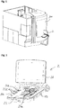
- Fig. 4A shows an exemplary perspective drawing of a receiving slot member 4 of the control system according to the embodiment of the invention (from an frontal-upper point of view).
- the receiving slot member 4 forms a part of the operator panel 2 described above, and has the receiving slot 23 into which the mobile data carrier 3 can be inserted.
- the receiving slot member 4 has an opening 46 into which a user can insert the mobile data carrier 3.
- the horizontal width of the opening 46 is larger than a width of the mobile data carrier 3 for enabling easier insertion of the mobile data carrier 3.
- Adjacent to the opening 46, the receiving slot member 4 has a tapered portion 44 of the receiving slot 23 which has a width that decreases from the opening 46 towards the inner side of the receiving slot 23 and merges into a receiving portion 43 of the receiving slot 23.
- the horizontal width of the receiving portion 43 is adjusted to the width of the mobile data carrier 3.
- the male USB connector plug 41 of the receiving slot member 4 is plugged into the female USB connector socket 31 of the mobile data carrier 3.
- the left and right lower lateral sides of the receiving portion 43 of the receiving slot 23 have respective elongated guiding protrusions 42a and 42b which are adapted to engage into the guiding grooves 32a and 32b of the mobile data carrier 3.
- This provides the advantage that the mobile data carrier 3 will be blocked by the guiding protrusions 42a and 42b when the user attempts to insert the mobile data carrier 3 with its back side having the holding portion 34 and when the user attempts to insert the mobile data carrier 3 with its front side but having the lower side facing upwards.
- the guiding protrusions 42a and 42b can block objects other than the mobile data carrier 3.
- the cross-sectional shapes of the guiding protrusions 42a and 42b and the cross-sectional shapes of the guiding grooves 32a and 32b are fitted to each other, and when inserting the mobile data carrier 3, the mobile data carrier 3 is guided in a correct position to the USB connector plug 41 for correctly connecting the USB connector plug 41 and the USB connector socket 31.
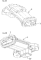
- Fig. 4B shows another exemplary perspective drawing (from a lower point of view) of the receiving slot member 4 of the control system according to the embodiment of the invention
- Fig. 4C shows an exemplary bottom-side view of the receiving slot member 4 of the control system according to the embodiment of the invention.
- the receiving slot member 4 has an opening 45 which is arranged at a lower end portion of the receiving portion 43 of the receiving slot 23 and which allows dirt and soot that may be present in the receiving slot 23 to fall out of the receiving slot 23 near the lower end portion of the receiving portion 43.
- the receiving slot member 4 may enter the receiving slot 23 and be pushed towards the end portion of the receiving portion 43 of the receiving slot 23 when inserting the mobile data carrier 3.
- Fig. 4D shows an exemplary front-side view of the receiving slot member 4 of the control system according to the embodiment of the invention.
- the receiving portion 43 of the receiving slot 23 may additionally be exemplarily provided with upper guiding protrusions 42c and 42d, which further may improve the mechanism of accurately guiding the mobile data carrier 3 during being inserted into the receiving slot 23 so that accurate connection between the connectors 41 and 31 may be achieved even more accurately.
- Fig. 4E shows an exemplary horizontal sectional view of the receiving slot member 4 of the control system along the section B-B in Fig. 4D
- Fig. 4F shows an exemplary vertical sectional view of the receiving slot member of the control system along the section A-A in Fig. 4D .
- the guiding protrusions 42a and 42b of the receiving portion 43 of the receiving slot 23 have an elongated shape and extend in parallel to each other and in a longitudinal direction (insertion direction of the mobile data carrier 3) of the receiving slot 23 and end portions thereof facing the direction towards the opening 46 form stopper portions 47a and 47b which come into contact with the stopper portions 33a and 33b or the mobile data carrier 3, respectively, when the guiding protrusions 42a and 42b engage into the guiding grooves 32a and 32b of the mobile data carrier 3, respectively, and when the mobile data carrier 3 is inserted into the receiving slot 23 up to a fully inserted position in which the connectors 31 and 41 are properly connected.
- Fig. 5A shows an exemplary perspective drawing of the receiving slot member 4 according to the embodiment of the invention together with the received mobile data carrier 3, wherein the mobile data carrier 3 is inserted into the receiving slot 23 up to the fully inserted position.
- Fig. 5B shows another exemplary perspective drawing of the receiving slot member 4 according to the embodiment of the invention together with the received mobile data carrier 3, wherein the mobile data carrier 3 is inserted into the receiving slot 23 up to the fully inserted position.
- Fig. 5C shows an exemplary front-side view of the receiving slot member 4 according to the embodiment of the invention together with the received mobile data carrier 3, wherein the mobile data carrier 3 is inserted into the receiving slot 23 up to the fully inserted position.
- Fig. 5D shows an exemplary vertical sectional view of the receiving slot member 4 according to the embodiment of the invention together with the received mobile data carrier 3 along the section A-A in Fig. 5C .
- the male connector plug 41 of the receiving slot member 4 is connected to the female connector socket 31 of the mobile data carrier 3.
- the height of the inner receiving portion of the receiving slot 23 is substantially equal (only slightly larger in order to allow for little clearance) than the height of the mobile data carrier 3 and the mobile data carrier 3 is received in the receiving slot such that most part thereof is received.
- the length of the portion of the mobile data carrier 3 (in the insertion direction) that is received inside the receiving slot 23 is preferably about more than three times the length of the male USB connector (preferably more than 3 cm and even more preferably more than 5 cm in case of a Type A male USB connector).
- the casing of the mobile data carrier 3 may be made of metal or at least comprise a frame made metal.
- Fig. 5E shows another exemplary vertical sectional view of the receiving slot member 4 according to the embodiment of the invention together with the received mobile data carrier 3 along the section C-C in Fig. 5D .
- the cross-sectional shape of the casing of the mobile data carrier 3 is adapted to fit the cross-sectional shape of the receiving portion 43 of the receiving slot 23, and the cross-sectional shape of the guiding protrusions 42 and 42b of the receiving slot 23 fits the cross-sectional shape of the guiding grooves 32a and 32b of the mobile data carrier.
- the mobile data carrier 3 can only be inserted with an upper side facing upwards (i.e. facing an upper side of the receiving portion 43) and with a lower side facing downwards (i.e. facing a lower side of the receiving portion 43). Accordingly, when the user attempts to insert the mobile data carrier upside down, the insertion movement will be blocked at least by the guiding protrusions 42a and 42b because they cannot engage with the guiding grooves 32a and 32b.
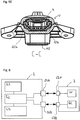
- Fig. 6 shows an exemplary schematic drawing of a control system according to a preferred embodiment of the present invention.
- the system comprises a mobile data carrier 3 and a control device having units 51, 52 and 53 of an operator console 2.
- the control device has a processing unit 52 such as a CPU or the like, a memory unit 51 and an input/output unit 53 configured to receive input by a user, and first and third communication interfaces 54A and 54B.
- the first communication interface 54A and the third communication interface 54B are connected to the processing unit 52, respectively.
- the processing unit 52 is connected to the memory unit 51 and the input/output unit 53.
- the mobile data carrier 3 comprises first and second memory means 61 and 62, and a second communication interface 63A and a fourth communication interface 63B, the second communication interface 63A being connected to the first memory means 61 and the fourth communication interface 63B being connected to the second memory means 62.
- the first communication interface 54A of the control device is adapted to communicably connect to the second communication interface 63A of the mobile data carrier 3, and the third communication interface 54B of the control device is adapted to communicably connect to the fourth communication interface 63B of the mobile data carrier 3.
- connection between the first and second communication interfaces 54A and 63A may be realized by a detachable wired connection, e.g., as discussed in connection with embodiments above, the second communication interface 63A may include the above described female connector socket 31 and the first communication interface 54A may include the above described male connector plug 41.
- the connection between the third and fourth communication interfaces 54B and 63B may be realized by a wireless connection, e.g., by Bluetooth, RFID, WLAN or the like.
- the third and fourth communication interfaces 54B and 63B may be adapted such that the wireless connection can be established when the mobile data carrier 3 and its communication interface 63A is directly connected via wired connection to the communication interface 54A.
- the wireless connection can be established at least at a relative position between the operator panel 2 and the mobile data carrier 3 at least when the mobile data carrier 3 and its communication interface 63A is directly connected via wired connection to the communication interface 54A, e.g.
- the receiving slot member may have attached to it (or provided in parallel) a wireless receiver (not shown above), e.g. such as an RFID receiver adjacent to the receiving slot 23.
- the mobile data carrier 3 may have an additional wireless transmitter (not shown above) such as an RFID transmitter.
- the control device in the exemplary embodiment may enable a user to control a plurality of available operation functions of the machine tool.
- the user may input his/her commands manually, using the input unit 53.
- the input unit 53 may for example comprise several keys, touch screens, joy sticks, track balls, a mouse, etc.
- the user may have to couple the mobile data carrier 3 to the control device (e.g. by inserting it into the receiving slot 23 as discussed above) such that the interfaces 54A and 63A communicate with each other, and that interfaces 54B and 63B communicate with each other.
- authorization data stored in the memory unit 62 of the mobile data carrier 3 can be read out via interfaces 54B and 63B from the memory means 62.
- the transferred authorization data can be analyzed by the processing unit 52 and may be temporarily stored in the memory unit 51.
- the processing unit 52 of the control device 2 determines, based on the received authorization data, if the user is allowed to operate the input unit 53, and if yes, which of the available operation functions of the machine tool he is allowed to control, using the input unit 53. If, for example, the processing unit 52 decides that the user can use all operation functions of the machine tool, then all signals sent from the input unit 53 to the processing unit 52 may be converted into corresponding operation function instructions sent to the machine tool.
- the memory means 62 is preferably read-only memory in order to prevent inadmissible modification of authorization data.
- the mobile data carrier 3 can additionally be coupled to the control device 2 via the interfaces 54A and 63A in order to read out data from the memory means 61.
- other data may be exchanged between the mobile data carrier 3 and the control device 2 via these interfaces 54A and 63A.
- operation function program code stored in the memory unit 61 may be transferred to the processing unit 52 and stored in the memory unit 51 as a selectable operation function which can be selected/controlled by the user via the input unit 53.
- the exchanged data may comprise operation function output data generated during execution of the operation function of the machine tool which is transferred from the control device 2 to the mobile data carrier 3 and stored in the memory unit 61.
- the processing unit 52 may search whether corresponding operation function input data is stored in the memory unit 61 of the mobile data carrier 3, and if yes, transfer this data to the processing unit 52 in order to be used in conjunction with the selected operation function.
- operation function input data may for example be information specifying which tools should be used by the machine tool during an operation function in order to machine a working piece, and where these tools are located.
- the processing unit 52 may be configured, after the user has terminated his work at the control device, to transfer all data generated in the control device 2 which is related to the operation functions carried out to storage means 61 of the mobile data carrier 3. In response to such a request, the processing unit 52 may send the corresponding data to the mobile data carrier 3 via interfaces 54A and 63A. The transmission of data between the mobile data carrier 3 and the control device 2 may be automatically triggered as soon as the interfaces communicate with each other. Alternatively, the user may be requested by the input unit 53 to give his consent that data is exchanged between the control device 2 and the mobile data carrier 3.
- Communication between the interfaces 54A and 63A, and between the interfaces 54B and 63B may be established simultaneously.
- a first coupling action only communication between the interfaces 54B and 63B is established (in order to read authorization data), and, after having initiated an additional coupling action, communication can be established between the interfaces 54A and 63A.
- the control device 2 comprises the slot 23, as exemplarily discussed above, and assuming that the mobile data carrier 3 can be inserted into the slot 23, in a first inserting position, only communication between the interfaces 54B and 63B may be established, wherein, upon further pushing the mobile data carrier 3 into the slot 23, a second coupling position is reached where also the physical connection between the interfaces 54A and 63A can be established (e.g. when the connector plug 41 connects to the connector socket 31).
- the authorization data received at the control device via the interfaces 54B and 63B is checked first as to whether the user is authorized to exchange data or which type of data he/she is authorized to exchange between the mobile data carrier 3 and the control device, and to then activate/enable communication via the interfaces 54A and 63A or not.
- control device may be configured to enable the user to control a plurality of available control functions of the machine tool 100 depending on an authorization level and/or access rights of the user.
- the storage means 62 of the mobile data carrier 3 may store access authorization data being indicative of the authorization level and/or access rights of the user, and the control device is then adapted to read access authorization data stored in the storage means 62 via an established connection between the communication interfaces 54B and 63B for determining the authorization level and/or access rights of the user, and/or the storage means 62 stores access authorization data being indicative of the authorization level and/or access rights of the user, and the other storage means 61 stores configuration data and/or control data.
- the mobile data carrier 3 may be adapted to be communicably connected to the control device of the operator console 2 via the wireless first connection being established between the wireless interfaces 54B and 63B and via a second connection being established between the communication interfaces 54A and 63B, e.g. when the mobile data carrier 3 is received in the receiving slot 23 of the operator console 2 as exemplarily discussed above.
- control device can be adapted to read access authorization data stored in the storage means 62 via the established wireless first connection for determining the authorization level and/or access rights of the user and is further adapted to read configuration data from the storage means 61 via the established second connection for configuring the control device and/or control data for controlling operation of the machine tool 100 based on the control data.
- the control device can be further adapted to write configuration data and/or control data to the storage means 61 via the established second connection (interfaces 63A and 54A), but the other storage means 62 is a read-only memory for preventing the control device to overwrite or alter data stored in the storage means 62.
Landscapes
- Engineering & Computer Science (AREA)
- Human Computer Interaction (AREA)
- Manufacturing & Machinery (AREA)
- Physics & Mathematics (AREA)
- General Physics & Mathematics (AREA)
- Automation & Control Theory (AREA)
- Numerical Control (AREA)
Claims (15)
- Système de commande d'une machine-outil à commande numérique par un utilisateur, comprenant- une console d'opérateur (2) pouvant être actionnée par l'utilisateur ; et- un support de données mobile (3) ;dans lequel la console d'opérateur (2) a un dispositif de commande pour commander la machine-outil (100), le dispositif de commande de la console d'opérateur (2) ayant une première interface de communication (54A) conçue pour être connectée de manière communicante à une deuxième interface de communication (63A) du support de données mobile (3) ;
caractérisé en ce que
la console d'opérateur (2) comprend une fente de réception (23) ayant un côté intérieur supérieur et un côté intérieur inférieur opposé au côté intérieur supérieur pour y insérer une partie d'insertion d'un boîtier allongé du support de données mobile (3) qui est formée à une première extrémité du support de données mobile (3), la fente de réception (23) ayant une forme intérieure allongée qui est formée de telle sorte que la partie d'insertion du boîtier allongé du support de données mobile (3) peut être insérée dans une partie de réception (43) de la fente de réception (23) de la console d'opérateur (2),
une prise de connecteur femelle de type USB est intégrée dans une partie avant de la partie d'insertion du boîtier allongé du support de données mobile (3), et
une fiche de connecteur mâle de type USB (41), qui est prévue sur une face d'extrémité intérieure à l'intérieur de la fente de réception (23) de la console d'opérateur (2), est enfichée dans le connecteur femelle (31) lorsque le support de données mobile (3) est inséré avec sa partie avant, dans laquelle la prise de connecteur femelle USB (31) est intégrée, dans la fente de réception (23) de la console d'opérateur (2). - Système selon la revendication 1, caractérisé en ce
qu'une forme en section transversale d'une partie de réception (43) de la fente de réception (23) est au moins partiellement conçue pour s'adapter à une forme en section transversale de la partie d'insertion du boîtier du support de données mobile (3) de telle sorte que la partie d'insertion du support de données mobile (3) peut être insérée dans la partie de réception (43) de la fente de réception (23) uniquement de telle sorte que le premier côté extérieur du boîtier du support de données mobile (3) soit en regard du premier côté intérieur de la fente de réception (23) et le second côté extérieur du boîtier du support de données mobile (3) en regard du second côté intérieur de la fente de réception (23). - Système selon la revendication 1 ou 2, caractérisé en ce que
la forme en section transversale de la partie de réception (43) de la fente de réception (23) est au moins partiellement formée pour s'adapter à la forme en section transversale de la partie d'insertion du support de données mobile (3) de telle sorte qu'un mouvement du support de données mobile (3) dans des directions perpendiculaires à une direction d'insertion de la fente de réception (23) est bloqué et/ou qu'une rotation du support de données mobile (3) autour de la direction d'insertion est bloquée lorsque la partie d'insertion du support de données mobile (3) est reçue dans la partie de réception (43) de la fente de réception (23). - Système selon l'une quelconque des revendications précédentes, caractérisé en ce
qu'une ouverture (46) de la fente de réception (23) a une largeur supérieure à une largeur de la partie d'insertion du support de données mobile (3), et une largeur d'une partie avant (44) de la fente de réception (23) diminue de l'ouverture (46) vers la partie de réception (43) de la fente de réception (23) ; et/ou
l'ouverture (46) de la fente de réception (23) a une hauteur supérieure à une hauteur de la partie d'insertion du support de données mobile (3), et une hauteur de la partie avant (44) de la fente de réception (23) diminue de l'ouverture (46) vers la partie de réception (43) de la fente de réception (23). - Système selon l'une quelconque des revendications précédentes, caractérisé en ce que
le boîtier du support de données mobile (3) a une partie de maintien (34) formée à une seconde extrémité du support de données mobile (3) sur le côté opposé à la prise de connecteur femelle (31),
une forme en section transversale de la partie de maintien (34) du boîtier du support de données mobile (3) étant formée de telle sorte que la partie de maintien (34) est bloquée par la forme en section transversale de la partie de réception (43) de la fente de réception (23). - Système selon l'une quelconque des revendications précédentes, caractérisé en ce que la partie de réception (43) de la fente de réception (23) a au moins une première partie d'arrêt (47a ; 47b) et la partie d'insertion du boîtier du support de données mobile (3) a au moins une seconde partie d'arrêt (33a ; 33b), ladite au moins une première partie d'arrêt (47a ; 47b) étant conçue pour venir en contact avec ladite au moins une seconde partie d'arrêt (33a ; 33b) pour bloquer un mouvement du support de données mobile (3) dans une direction d'insertion lorsque la partie d'insertion du support de données mobile (3) est insérée dans la partie de réception (43) de la fente de réception (23) jusqu'à une position complètement insérée du support de données mobile (3).
- Système selon l'une quelconque des revendications précédentes, caractérisé en ce que
la partie de réception (43) de la fente de réception (23) a au moins une saillie de guidage (42a ; 42b) et la partie d'insertion du boîtier du support de données mobile (3) a au moins une rainure de guidage (32a ; 32b) conçue pour s'adapter à ladite au moins une saillie de guidage (42a ; 42b) de la partie de réception (43), ladite au moins une saillie de guidage (42a ; 42b) étant conçue pour s'engager dans ladite au moins une rainure de guidage (32a ; 32b) lors de l'insertion de la partie d'insertion du boîtier du support de données mobile (3) dans la partie de réception (43) de la fente de réception (23) ; et/ou
la partie de réception de la fente de réception (23) a au moins une rainure de guidage et la partie d'insertion du boîtier du support de données mobile (3) a au moins une saillie de guidage conçue pour s'adapter à ladite au moins une rainure de guidage de la partie de réception, ladite au moins une saillie de guidage étant conçue pour s'engager dans ladite au moins une rainure de guidage lors de l'insertion de la partie d'insertion du boîtier du support de données mobile (3) dans la partie de réception de la fente de réception (23). - Système selon l'une quelconque des revendications précédentes, caractérisé en ce que
le boîtier du support de données mobile (3) comprend une partie cadre extérieur en métal. - Système selon l'une quelconque des revendications précédentes, caractérisé en ce que
la prise de connecteur femelle du support de données mobile est une prise de connecteur femelle USB (31) et la fiche de connecteur mâle du dispositif de commande est une fiche de connecteur mâle USB (41). - Système selon l'une quelconque des revendications précédentes, caractérisé en ce que
le dispositif de commande est configuré pour permettre à l'utilisateur de commander une pluralité de fonctions de commande disponibles de la machine-outil (100) en fonction d'un niveau d'autorisation et/ou de droits d'accès de l'utilisateur ;
dans lequel le support de données mobile (3) a un premier moyen de stockage stockant des données d'autorisation d'accès qui sont indicatives du niveau d'autorisation et/ou des droits d'accès de l'utilisateur, et le dispositif de commande est conçu pour lire les données d'autorisation d'accès stockées dans le premier moyen de stockage via une connexion établie entre la première et la deuxième interface de communication pour déterminer le niveau d'autorisation et/ou les droits d'accès de l'utilisateur ; ou
dans lequel le support de données mobile (3) a un premier moyen de stockage (62) stockant des données d'autorisation d'accès qui sont indicatives du niveau d'autorisation et/ou des droits d'accès de l'utilisateur et un second moyen de stockage (61) stockant des données de configuration et/ou des données de commande,
le dispositif de commande (51, 52, 53) de la console d'opérateur (2) a une troisième interface de communication sans fil (54B) et le support de données mobile (3) a une quatrième interface de communication sans fil (63B),
le support de données mobile (3) étant conçu pour être connecté de manière communicante au dispositif de commande (51, 52, 53) de la console d'opérateur (2) via une première connexion sans fil établie entre les troisième et quatrième interfaces de communication sans fil (54B, 63B) et via une seconde connexion établie entre les première et deuxième interfaces de communication (54A, 63A) lorsque le support de données mobile (3) est reçu dans la fente de réception (23) de la console d'opérateur (2), et
le dispositif de commande (51, 52, 53) est conçu pour lire des données d'autorisation d'accès stockées dans le premier moyen de stockage (62) via la première connexion sans fil établie pour déterminer le niveau d'autorisation et/ou les droits d'accès de l'utilisateur et est en outre conçu pour lire des données de configuration à partir du second moyen de stockage (61) via la seconde connexion établie pour configurer le dispositif de commande (51, 52, 53) et/ou des données de commande pour commander le fonctionnement de la machine-outil (100) sur la base des données de commande. - Système selon la revendication 10, caractérisé en ce que
le dispositif de commande (51, 52, 53) est en outre conçu pour écrire des données de configuration et/ou des données de commande dans le second moyen de stockage (61) via la seconde connexion établie ; et
le premier moyen de stockage (62) est une mémoire à lecture seule pour empêcher le dispositif de commande d'écraser ou de modifier des données stockées dans le premier moyen de stockage (62). - Système selon la revendication 10 ou 11, caractérisé en ce que
la troisième interface de communication sans fil (54B) du dispositif de commande a un lecteur RFID et la quatrième interface de communication sans fil (63B) du support de données mobile (3) a un transpondeur RFID. - Système selon l'une quelconque des revendications précédentes, caractérisé en ce
qu'un fond de la fente de réception (23) comprend une ouverture de sortie d'impuretés (45) prévue à une partie d'extrémité intérieure de la fente de réception (23), permettant aux impuretés poussées dans la fente de réception (23) par le support de données mobile inséré (3) d'être retirées de la fente de réception (23). - Console d'opérateur destinée à être utilisée dans un système de commande d'une machine-outil à commande numérique par un utilisateur selon l'une quelconque des revendications 1 à 13, comprenant :- un dispositif de commande pour commander la machine-outil (100) ; et- une fente de réception (23) ayant un côté intérieur supérieur et un côté intérieur inférieur opposé au côté intérieur supérieur pour y insérer une partie d'insertion d'un boîtier allongé du support de données mobile (3) qui est formée à une première extrémité du support de données mobile (3), la fente de réception (23) ayant une forme intérieure allongée qui est formée de telle sorte que la partie d'insertion du boîtier allongé du support de données mobile (3) peut être insérée dans une partie de réception (43) de la fente de réception (23) de la console d'opérateur (2) ;le dispositif de commande de la console d'opérateur (2) ayant une première interface de communication conçue pour être connectée de manière communicante à une deuxième interface de communication du support de données mobile (3) ;
la première interface de communication incluant une fiche de connecteur mâle de type USB (41) prévue sur une partie face d'extrémité intérieure de la fente de réception (23) pour être enfichée dans la prise de connecteur femelle (31) du support de données mobile (3) lorsque le support de données mobile (3) est inséré avec sa partie avant, dans laquelle la prise de connecteur femelle USB (31) est intégrée, dans la fente de réception (23) de la console d'opérateur (2). - Support de données mobile destiné à être utilisé dans un système de commande d'une machine-outil à commande numérique par un utilisateur selon l'une quelconque des revendications 1 à 13, comprenant :- une deuxième interface de communication incluant une prise de connecteur femelle de type USB (31) ; et- un boîtier allongé ayant un côté extérieur supérieur et un côté extérieur inférieur opposé au côté extérieur supérieur, et ayant une partie d'insertion formée à une première extrémité du support de données mobile (3) du côté de la prise de connecteur femelle de type USB (31) ;le support de données mobile (3) étant conçu pour pouvoir être inséré dans une fente de réception (23) d'une console d'opérateur (2) pouvant être actionnée par l'utilisateur et ayant un dispositif de commande pour commander la machine-outil (100), la fente de réception (23) ayant une forme allongée avec un côté intérieur supérieur et un côté intérieur inférieur opposé au côté intérieur supérieur, et
la deuxième interface de communication du support de données mobile (3) étant conçue pour être connectée de manière communicante à une première interface de communication du dispositif de commande, la prise de connecteur femelle de type USB (31) du support de données mobile (3) étant conçue pour être connectée à une fiche de connecteur mâle de type USB (41) prévue sur une partie face d'extrémité intérieure de la fente de réception (23) lorsque le support de données mobile (3) est inséré avec sa partie avant, dans laquelle la prise de connecteur femelle USB (31) est intégrée, dans la fente de réception (23) de la console d'opérateur (2).
Priority Applications (7)
| Application Number | Priority Date | Filing Date | Title |
|---|---|---|---|
| EP13184341.9A EP2849012B1 (fr) | 2013-09-13 | 2013-09-13 | Système de commande, console d'opérateur et support de données mobiles pour machine-outil |
| ES13184341T ES2706374T3 (es) | 2013-09-13 | 2013-09-13 | Sistema de control, consola de operador y soporte de datos móvil para una máquina herramienta |
| PCT/EP2014/069407 WO2015036492A2 (fr) | 2013-09-13 | 2014-09-11 | Système de commande, pupitre d'opérateur et support de données mobile pour une machine-outil |
| KR1020167006976A KR20160053938A (ko) | 2013-09-13 | 2014-09-11 | 모바일 데이터 캐리어를 가지는 머신 툴을 위한 제어 시스템 및 오퍼레이터 콘솔 |
| JP2016542312A JP6553621B2 (ja) | 2013-09-13 | 2014-09-11 | 数値制御工作機械のための制御システム、オペレータコンソールおよびモバイルデータ担体 |
| CN201480048673.2A CN105593771B (zh) | 2013-09-13 | 2014-09-11 | 用于机床的控制系统,操作员控制台和移动数据载体 |
| US15/021,730 US10274928B2 (en) | 2013-09-13 | 2014-09-11 | Control system, operator console and mobile data carrier for a machine tool |
Applications Claiming Priority (1)
| Application Number | Priority Date | Filing Date | Title |
|---|---|---|---|
| EP13184341.9A EP2849012B1 (fr) | 2013-09-13 | 2013-09-13 | Système de commande, console d'opérateur et support de données mobiles pour machine-outil |
Publications (2)
| Publication Number | Publication Date |
|---|---|
| EP2849012A1 EP2849012A1 (fr) | 2015-03-18 |
| EP2849012B1 true EP2849012B1 (fr) | 2018-11-14 |
Family
ID=49182125
Family Applications (1)
| Application Number | Title | Priority Date | Filing Date |
|---|---|---|---|
| EP13184341.9A Not-in-force EP2849012B1 (fr) | 2013-09-13 | 2013-09-13 | Système de commande, console d'opérateur et support de données mobiles pour machine-outil |
Country Status (7)
| Country | Link |
|---|---|
| US (1) | US10274928B2 (fr) |
| EP (1) | EP2849012B1 (fr) |
| JP (1) | JP6553621B2 (fr) |
| KR (1) | KR20160053938A (fr) |
| CN (1) | CN105593771B (fr) |
| ES (1) | ES2706374T3 (fr) |
| WO (1) | WO2015036492A2 (fr) |
Families Citing this family (5)
| Publication number | Priority date | Publication date | Assignee | Title |
|---|---|---|---|---|
| EP2848357A1 (fr) * | 2013-09-13 | 2015-03-18 | Dmg Mori Seiki Aktiengesellschaft | Dispositif pour porter le panneau de contrôle d'une machine-outil |
| KR102400839B1 (ko) * | 2015-07-08 | 2022-05-24 | 두산공작기계 주식회사 | 공작기계용 조작패널 유닛 |
| JP1549416S (fr) * | 2015-09-30 | 2016-05-16 | ||
| JP6495202B2 (ja) | 2016-06-20 | 2019-04-03 | キタムラ機械株式会社 | 工作機械用nc機能付操作盤 |
| DE102019108049A1 (de) * | 2019-03-28 | 2020-10-01 | Pilz Gmbh & Co. Kg | Zugriffssteuerungssystem zur Steuerung eines Zugriffs eines Nutzers auf eine oder mehrere Betriebsfunktionen einer technischen Anlage |
Family Cites Families (20)
| Publication number | Priority date | Publication date | Assignee | Title |
|---|---|---|---|---|
| JPS60187575U (ja) * | 1984-05-22 | 1985-12-12 | 三菱電機株式会社 | 数値制御装置 |
| CA2018400C (fr) * | 1989-06-07 | 1993-08-24 | Tsunesuke Takano | Connecteurs electriques |
| JP2993158B2 (ja) * | 1990-04-05 | 1999-12-20 | 三菱電機株式会社 | 数値制御装置 |
| JPH05265524A (ja) * | 1992-03-23 | 1993-10-15 | Sony Corp | ロボットの数値制御装置及びその生産管理方法 |
| JP2742502B2 (ja) * | 1993-10-18 | 1998-04-22 | 山一電機株式会社 | ダスト排出手段を備えたicソケット |
| US6017118A (en) * | 1995-04-27 | 2000-01-25 | Hewlett-Packard Company | High performance ink container with efficient construction |
| US20020163440A1 (en) * | 2001-03-01 | 2002-11-07 | Tsui Philip Y.W. | Programmable universal transmitter |
| JP2007220557A (ja) * | 2006-02-17 | 2007-08-30 | Tyco Electronics Amp Kk | 電気コネクタ組立体 |
| DE102007041768B4 (de) | 2007-09-04 | 2010-03-04 | Deckel Maho Pfronten Gmbh | System zur Steuerung des Zugriffs auf eine Werkzeugmaschine |
| DE102007045593A1 (de) * | 2007-09-14 | 2009-03-26 | Index-Werke Gmbh & Co. Kg Hahn & Tessky | Virtuelle Werkzeugmaschine zur Darstellung von Aktionen von Bearbeitungseinheiten einer realen Werkzeugmaschine |
| DE102008008646A1 (de) * | 2008-02-11 | 2009-08-13 | Robert Bosch Gmbh | CNC-Steuerung und Verfahren zur Datenübertragung |
| DE102008041074B4 (de) * | 2008-08-07 | 2010-07-08 | Kuka Roboter Gmbh | Programmierhandgerät und Verfahren zum Programmieren einer programmierbaren Maschine |
| JP2012006647A (ja) * | 2010-06-28 | 2012-01-12 | Kawashima Packaging Mach Ltd | 包装機械管理システム |
| JP2012040919A (ja) * | 2010-08-18 | 2012-03-01 | Fujitsu Ten Ltd | Usbメモリ接続機構とそれを備えた車載用電子機器 |
| CN102692950B (zh) * | 2011-03-22 | 2014-12-31 | 鸿富锦精密工业(深圳)有限公司 | 电子装置 |
| US9283931B2 (en) * | 2011-12-12 | 2016-03-15 | Mill Mountain Capital, LLC | Systems, devices and methods for vehicles |
| CN103187662A (zh) * | 2011-12-27 | 2013-07-03 | 鸿富锦精密工业(武汉)有限公司 | Usb板端连接器 |
| US20130179610A1 (en) * | 2012-01-10 | 2013-07-11 | Kleer LTD | Usb device with pass-through hub connection |
| CN202694334U (zh) * | 2012-04-27 | 2013-01-23 | 北京凯恩帝自动化科技有限公司 | 数据传输装置、装置外壳和装置锁定机构 |
| US9058550B2 (en) * | 2013-01-04 | 2015-06-16 | Google Technology Holdings LLC | Mobile devices with RFID capabilities and corresponding memory write methods |
-
2013
- 2013-09-13 EP EP13184341.9A patent/EP2849012B1/fr not_active Not-in-force
- 2013-09-13 ES ES13184341T patent/ES2706374T3/es active Active
-
2014
- 2014-09-11 JP JP2016542312A patent/JP6553621B2/ja active Active
- 2014-09-11 US US15/021,730 patent/US10274928B2/en active Active
- 2014-09-11 KR KR1020167006976A patent/KR20160053938A/ko not_active Ceased
- 2014-09-11 CN CN201480048673.2A patent/CN105593771B/zh not_active Expired - Fee Related
- 2014-09-11 WO PCT/EP2014/069407 patent/WO2015036492A2/fr not_active Ceased
Also Published As
| Publication number | Publication date |
|---|---|
| ES2706374T3 (es) | 2019-03-28 |
| US10274928B2 (en) | 2019-04-30 |
| KR20160053938A (ko) | 2016-05-13 |
| CN105593771A (zh) | 2016-05-18 |
| CN105593771B (zh) | 2020-01-17 |
| JP6553621B2 (ja) | 2019-07-31 |
| JP2016537745A (ja) | 2016-12-01 |
| WO2015036492A3 (fr) | 2015-07-02 |
| EP2849012A1 (fr) | 2015-03-18 |
| WO2015036492A2 (fr) | 2015-03-19 |
| US20160224009A1 (en) | 2016-08-04 |
Similar Documents
| Publication | Publication Date | Title |
|---|---|---|
| US10274928B2 (en) | Control system, operator console and mobile data carrier for a machine tool | |
| JP7158417B2 (ja) | 集塵機を制御するためのエネルギー蓄積器モジュール | |
| US20210137341A1 (en) | Cleaning apparatus and cleaning system | |
| CN101815598B (zh) | 移动式动力起子扳手操作装置 | |
| US9595701B2 (en) | Handheld tool, handheld tool add-on measuring device and handheld tool battery | |
| JP6145176B2 (ja) | 医療機器の無線制御のための方法及びデバイス | |
| EP3051658B1 (fr) | Bloc batterie et système d'outil électrique | |
| EP2194434B1 (fr) | système robotique | |
| US7173513B2 (en) | Electrical appliance with communication interface | |
| US10503680B2 (en) | Method for operating an automation device | |
| US20040140955A1 (en) | Input device for a computer and method of operation | |
| JP7106577B2 (ja) | 集塵機を制御するためのシステムコンポーネントとしての電気器具 | |
| CN103841916A (zh) | 用于可拆卸地将医疗器械、尤其是牙科器械连接到驱动单元或供给软管的连接装置 | |
| AU2014234239B2 (en) | Kitchen appliance operable by electric motor, data memory element, and combination of a kitchen appliance operable by electric motor and a data memory element | |
| CN104981304A (zh) | 用于冲压机或压力机的显示装置 | |
| US20040106331A1 (en) | Modular electrical device combination | |
| JP6187354B2 (ja) | 携帯機器用カバー | |
| JP2023544206A (ja) | ワイヤレスセンサパッケージを有する空圧ファスニング工具 | |
| CN117811598A (zh) | 可插拔无线模块、包括该模块的系统和该模块的制造方法 | |
| US20250139218A1 (en) | Cryptographically communicable token for mechanical coupling and communication with hand-held tools | |
| US6390834B1 (en) | Protective device for a plug connector | |
| JP7791847B2 (ja) | 位置検出を有する医療用ストップコックアセンブリ | |
| CN211427439U (zh) | 储物单元 | |
| US20240394348A1 (en) | Token for user-related control of a craftsman device | |
| KR100862627B1 (ko) | 스마트 칩을 갖는 usb 장치 |
Legal Events
| Date | Code | Title | Description |
|---|---|---|---|
| PUAI | Public reference made under article 153(3) epc to a published international application that has entered the european phase |
Free format text: ORIGINAL CODE: 0009012 |
|
| 17P | Request for examination filed |
Effective date: 20130913 |
|
| AK | Designated contracting states |
Kind code of ref document: A1 Designated state(s): AL AT BE BG CH CY CZ DE DK EE ES FI FR GB GR HR HU IE IS IT LI LT LU LV MC MK MT NL NO PL PT RO RS SE SI SK SM TR |
|
| AX | Request for extension of the european patent |
Extension state: BA ME |
|
| R17P | Request for examination filed (corrected) |
Effective date: 20150918 |
|
| RBV | Designated contracting states (corrected) |
Designated state(s): AL AT BE BG CH CY CZ DE DK EE ES FI FR GB GR HR HU IE IS IT LI LT LU LV MC MK MT NL NO PL PT RO RS SE SI SK SM TR |
|
| 17Q | First examination report despatched |
Effective date: 20160128 |
|
| STAA | Information on the status of an ep patent application or granted ep patent |
Free format text: STATUS: EXAMINATION IS IN PROGRESS |
|
| GRAP | Despatch of communication of intention to grant a patent |
Free format text: ORIGINAL CODE: EPIDOSNIGR1 |
|
| STAA | Information on the status of an ep patent application or granted ep patent |
Free format text: STATUS: GRANT OF PATENT IS INTENDED |
|
| INTG | Intention to grant announced |
Effective date: 20180514 |
|
| GRAS | Grant fee paid |
Free format text: ORIGINAL CODE: EPIDOSNIGR3 |
|
| GRAA | (expected) grant |
Free format text: ORIGINAL CODE: 0009210 |
|
| STAA | Information on the status of an ep patent application or granted ep patent |
Free format text: STATUS: THE PATENT HAS BEEN GRANTED |
|
| AK | Designated contracting states |
Kind code of ref document: B1 Designated state(s): AL AT BE BG CH CY CZ DE DK EE ES FI FR GB GR HR HU IE IS IT LI LT LU LV MC MK MT NL NO PL PT RO RS SE SI SK SM TR |
|
| REG | Reference to a national code |
Ref country code: CH Ref legal event code: EP Ref country code: AT Ref legal event code: REF Ref document number: 1065561 Country of ref document: AT Kind code of ref document: T Effective date: 20181115 |
|
| REG | Reference to a national code |
Ref country code: DE Ref legal event code: R096 Ref document number: 602013046589 Country of ref document: DE |
|
| REG | Reference to a national code |
Ref country code: IE Ref legal event code: FG4D |
|
| REG | Reference to a national code |
Ref country code: NL Ref legal event code: MP Effective date: 20181114 |
|
| REG | Reference to a national code |
Ref country code: LT Ref legal event code: MG4D |
|
| REG | Reference to a national code |
Ref country code: ES Ref legal event code: FG2A Ref document number: 2706374 Country of ref document: ES Kind code of ref document: T3 Effective date: 20190328 |
|
| REG | Reference to a national code |
Ref country code: AT Ref legal event code: MK05 Ref document number: 1065561 Country of ref document: AT Kind code of ref document: T Effective date: 20181114 |
|
| PG25 | Lapsed in a contracting state [announced via postgrant information from national office to epo] |
Ref country code: LV Free format text: LAPSE BECAUSE OF FAILURE TO SUBMIT A TRANSLATION OF THE DESCRIPTION OR TO PAY THE FEE WITHIN THE PRESCRIBED TIME-LIMIT Effective date: 20181114 Ref country code: LT Free format text: LAPSE BECAUSE OF FAILURE TO SUBMIT A TRANSLATION OF THE DESCRIPTION OR TO PAY THE FEE WITHIN THE PRESCRIBED TIME-LIMIT Effective date: 20181114 Ref country code: HR Free format text: LAPSE BECAUSE OF FAILURE TO SUBMIT A TRANSLATION OF THE DESCRIPTION OR TO PAY THE FEE WITHIN THE PRESCRIBED TIME-LIMIT Effective date: 20181114 Ref country code: BG Free format text: LAPSE BECAUSE OF FAILURE TO SUBMIT A TRANSLATION OF THE DESCRIPTION OR TO PAY THE FEE WITHIN THE PRESCRIBED TIME-LIMIT Effective date: 20190214 Ref country code: FI Free format text: LAPSE BECAUSE OF FAILURE TO SUBMIT A TRANSLATION OF THE DESCRIPTION OR TO PAY THE FEE WITHIN THE PRESCRIBED TIME-LIMIT Effective date: 20181114 Ref country code: NO Free format text: LAPSE BECAUSE OF FAILURE TO SUBMIT A TRANSLATION OF THE DESCRIPTION OR TO PAY THE FEE WITHIN THE PRESCRIBED TIME-LIMIT Effective date: 20190214 Ref country code: IS Free format text: LAPSE BECAUSE OF FAILURE TO SUBMIT A TRANSLATION OF THE DESCRIPTION OR TO PAY THE FEE WITHIN THE PRESCRIBED TIME-LIMIT Effective date: 20190314 Ref country code: AT Free format text: LAPSE BECAUSE OF FAILURE TO SUBMIT A TRANSLATION OF THE DESCRIPTION OR TO PAY THE FEE WITHIN THE PRESCRIBED TIME-LIMIT Effective date: 20181114 |
|
| PG25 | Lapsed in a contracting state [announced via postgrant information from national office to epo] |
Ref country code: NL Free format text: LAPSE BECAUSE OF FAILURE TO SUBMIT A TRANSLATION OF THE DESCRIPTION OR TO PAY THE FEE WITHIN THE PRESCRIBED TIME-LIMIT Effective date: 20181114 Ref country code: RS Free format text: LAPSE BECAUSE OF FAILURE TO SUBMIT A TRANSLATION OF THE DESCRIPTION OR TO PAY THE FEE WITHIN THE PRESCRIBED TIME-LIMIT Effective date: 20181114 Ref country code: GR Free format text: LAPSE BECAUSE OF FAILURE TO SUBMIT A TRANSLATION OF THE DESCRIPTION OR TO PAY THE FEE WITHIN THE PRESCRIBED TIME-LIMIT Effective date: 20190215 Ref country code: SE Free format text: LAPSE BECAUSE OF FAILURE TO SUBMIT A TRANSLATION OF THE DESCRIPTION OR TO PAY THE FEE WITHIN THE PRESCRIBED TIME-LIMIT Effective date: 20181114 Ref country code: AL Free format text: LAPSE BECAUSE OF FAILURE TO SUBMIT A TRANSLATION OF THE DESCRIPTION OR TO PAY THE FEE WITHIN THE PRESCRIBED TIME-LIMIT Effective date: 20181114 Ref country code: PT Free format text: LAPSE BECAUSE OF FAILURE TO SUBMIT A TRANSLATION OF THE DESCRIPTION OR TO PAY THE FEE WITHIN THE PRESCRIBED TIME-LIMIT Effective date: 20190314 |
|
| PG25 | Lapsed in a contracting state [announced via postgrant information from national office to epo] |
Ref country code: DK Free format text: LAPSE BECAUSE OF FAILURE TO SUBMIT A TRANSLATION OF THE DESCRIPTION OR TO PAY THE FEE WITHIN THE PRESCRIBED TIME-LIMIT Effective date: 20181114 Ref country code: CZ Free format text: LAPSE BECAUSE OF FAILURE TO SUBMIT A TRANSLATION OF THE DESCRIPTION OR TO PAY THE FEE WITHIN THE PRESCRIBED TIME-LIMIT Effective date: 20181114 Ref country code: PL Free format text: LAPSE BECAUSE OF FAILURE TO SUBMIT A TRANSLATION OF THE DESCRIPTION OR TO PAY THE FEE WITHIN THE PRESCRIBED TIME-LIMIT Effective date: 20181114 |
|
| REG | Reference to a national code |
Ref country code: DE Ref legal event code: R097 Ref document number: 602013046589 Country of ref document: DE |
|
| PG25 | Lapsed in a contracting state [announced via postgrant information from national office to epo] |
Ref country code: SK Free format text: LAPSE BECAUSE OF FAILURE TO SUBMIT A TRANSLATION OF THE DESCRIPTION OR TO PAY THE FEE WITHIN THE PRESCRIBED TIME-LIMIT Effective date: 20181114 Ref country code: RO Free format text: LAPSE BECAUSE OF FAILURE TO SUBMIT A TRANSLATION OF THE DESCRIPTION OR TO PAY THE FEE WITHIN THE PRESCRIBED TIME-LIMIT Effective date: 20181114 Ref country code: EE Free format text: LAPSE BECAUSE OF FAILURE TO SUBMIT A TRANSLATION OF THE DESCRIPTION OR TO PAY THE FEE WITHIN THE PRESCRIBED TIME-LIMIT Effective date: 20181114 Ref country code: SM Free format text: LAPSE BECAUSE OF FAILURE TO SUBMIT A TRANSLATION OF THE DESCRIPTION OR TO PAY THE FEE WITHIN THE PRESCRIBED TIME-LIMIT Effective date: 20181114 |
|
| PLBE | No opposition filed within time limit |
Free format text: ORIGINAL CODE: 0009261 |
|
| STAA | Information on the status of an ep patent application or granted ep patent |
Free format text: STATUS: NO OPPOSITION FILED WITHIN TIME LIMIT |
|
| 26N | No opposition filed |
Effective date: 20190815 |
|
| PG25 | Lapsed in a contracting state [announced via postgrant information from national office to epo] |
Ref country code: SI Free format text: LAPSE BECAUSE OF FAILURE TO SUBMIT A TRANSLATION OF THE DESCRIPTION OR TO PAY THE FEE WITHIN THE PRESCRIBED TIME-LIMIT Effective date: 20181114 |
|
| PGFP | Annual fee paid to national office [announced via postgrant information from national office to epo] |
Ref country code: FR Payment date: 20190924 Year of fee payment: 7 Ref country code: IT Payment date: 20190920 Year of fee payment: 7 |
|
| PGFP | Annual fee paid to national office [announced via postgrant information from national office to epo] |
Ref country code: CH Payment date: 20190924 Year of fee payment: 7 |
|
| PGFP | Annual fee paid to national office [announced via postgrant information from national office to epo] |
Ref country code: ES Payment date: 20191023 Year of fee payment: 7 |
|
| PG25 | Lapsed in a contracting state [announced via postgrant information from national office to epo] |
Ref country code: TR Free format text: LAPSE BECAUSE OF FAILURE TO SUBMIT A TRANSLATION OF THE DESCRIPTION OR TO PAY THE FEE WITHIN THE PRESCRIBED TIME-LIMIT Effective date: 20181114 |
|
| PG25 | Lapsed in a contracting state [announced via postgrant information from national office to epo] |
Ref country code: MC Free format text: LAPSE BECAUSE OF FAILURE TO SUBMIT A TRANSLATION OF THE DESCRIPTION OR TO PAY THE FEE WITHIN THE PRESCRIBED TIME-LIMIT Effective date: 20181114 |
|
| PG25 | Lapsed in a contracting state [announced via postgrant information from national office to epo] |
Ref country code: LU Free format text: LAPSE BECAUSE OF NON-PAYMENT OF DUE FEES Effective date: 20190913 Ref country code: IE Free format text: LAPSE BECAUSE OF NON-PAYMENT OF DUE FEES Effective date: 20190913 |
|
| REG | Reference to a national code |
Ref country code: BE Ref legal event code: MM Effective date: 20190930 |
|
| PG25 | Lapsed in a contracting state [announced via postgrant information from national office to epo] |
Ref country code: BE Free format text: LAPSE BECAUSE OF NON-PAYMENT OF DUE FEES Effective date: 20190930 |
|
| PGFP | Annual fee paid to national office [announced via postgrant information from national office to epo] |
Ref country code: GB Payment date: 20200923 Year of fee payment: 8 |
|
| PGFP | Annual fee paid to national office [announced via postgrant information from national office to epo] |
Ref country code: DE Payment date: 20200930 Year of fee payment: 8 |
|
| REG | Reference to a national code |
Ref country code: CH Ref legal event code: PL |
|
| PG25 | Lapsed in a contracting state [announced via postgrant information from national office to epo] |
Ref country code: CY Free format text: LAPSE BECAUSE OF FAILURE TO SUBMIT A TRANSLATION OF THE DESCRIPTION OR TO PAY THE FEE WITHIN THE PRESCRIBED TIME-LIMIT Effective date: 20181114 |
|
| PG25 | Lapsed in a contracting state [announced via postgrant information from national office to epo] |
Ref country code: HU Free format text: LAPSE BECAUSE OF FAILURE TO SUBMIT A TRANSLATION OF THE DESCRIPTION OR TO PAY THE FEE WITHIN THE PRESCRIBED TIME-LIMIT; INVALID AB INITIO Effective date: 20130913 Ref country code: MT Free format text: LAPSE BECAUSE OF FAILURE TO SUBMIT A TRANSLATION OF THE DESCRIPTION OR TO PAY THE FEE WITHIN THE PRESCRIBED TIME-LIMIT Effective date: 20181114 Ref country code: FR Free format text: LAPSE BECAUSE OF NON-PAYMENT OF DUE FEES Effective date: 20200930 |
|
| PG25 | Lapsed in a contracting state [announced via postgrant information from national office to epo] |
Ref country code: LI Free format text: LAPSE BECAUSE OF NON-PAYMENT OF DUE FEES Effective date: 20200930 Ref country code: CH Free format text: LAPSE BECAUSE OF NON-PAYMENT OF DUE FEES Effective date: 20200930 |
|
| PG25 | Lapsed in a contracting state [announced via postgrant information from national office to epo] |
Ref country code: IT Free format text: LAPSE BECAUSE OF NON-PAYMENT OF DUE FEES Effective date: 20200913 |
|
| REG | Reference to a national code |
Ref country code: ES Ref legal event code: FD2A Effective date: 20220117 |
|
| REG | Reference to a national code |
Ref country code: DE Ref legal event code: R119 Ref document number: 602013046589 Country of ref document: DE |
|
| GBPC | Gb: european patent ceased through non-payment of renewal fee |
Effective date: 20210913 |
|
| PG25 | Lapsed in a contracting state [announced via postgrant information from national office to epo] |
Ref country code: ES Free format text: LAPSE BECAUSE OF NON-PAYMENT OF DUE FEES Effective date: 20200914 |
|
| PG25 | Lapsed in a contracting state [announced via postgrant information from national office to epo] |
Ref country code: MK Free format text: LAPSE BECAUSE OF FAILURE TO SUBMIT A TRANSLATION OF THE DESCRIPTION OR TO PAY THE FEE WITHIN THE PRESCRIBED TIME-LIMIT Effective date: 20181114 |
|
| PG25 | Lapsed in a contracting state [announced via postgrant information from national office to epo] |
Ref country code: GB Free format text: LAPSE BECAUSE OF NON-PAYMENT OF DUE FEES Effective date: 20210913 Ref country code: DE Free format text: LAPSE BECAUSE OF NON-PAYMENT OF DUE FEES Effective date: 20220401 |