EP2849302A1 - Dispositif de gestion de l'énergie, procédé de gestion de l'énergie et programme - Google Patents
Dispositif de gestion de l'énergie, procédé de gestion de l'énergie et programme Download PDFInfo
- Publication number
- EP2849302A1 EP2849302A1 EP20130788649 EP13788649A EP2849302A1 EP 2849302 A1 EP2849302 A1 EP 2849302A1 EP 20130788649 EP20130788649 EP 20130788649 EP 13788649 A EP13788649 A EP 13788649A EP 2849302 A1 EP2849302 A1 EP 2849302A1
- Authority
- EP
- European Patent Office
- Prior art keywords
- power
- amount
- target value
- sold
- electric power
- Prior art date
- Legal status (The legal status is an assumption and is not a legal conclusion. Google has not performed a legal analysis and makes no representation as to the accuracy of the status listed.)
- Granted
Links
Images


Classifications
-
- H—ELECTRICITY
- H02—GENERATION; CONVERSION OR DISTRIBUTION OF ELECTRIC POWER
- H02J—ELECTRIC POWER NETWORKS; CIRCUIT ARRANGEMENTS OR SYSTEMS FOR SUPPLYING OR DISTRIBUTING ELECTRIC POWER; SYSTEMS FOR STORING ELECTRIC ENERGY
- H02J3/00—Circuit arrangements for AC mains or AC distribution networks
- H02J3/008—Circuit arrangements for power supply or distribution technologies responsive to energy trading
-
- G—PHYSICS
- G05—CONTROLLING; REGULATING
- G05B—CONTROL OR REGULATING SYSTEMS IN GENERAL; FUNCTIONAL ELEMENTS OF SUCH SYSTEMS; MONITORING OR TESTING ARRANGEMENTS FOR SUCH SYSTEMS OR ELEMENTS
- G05B15/00—Systems controlled by a computer
- G05B15/02—Systems controlled by a computer electric
-
- G—PHYSICS
- G05—CONTROLLING; REGULATING
- G05F—SYSTEMS FOR REGULATING ELECTRIC OR MAGNETIC VARIABLES
- G05F1/00—Automatic systems in which deviations of an electric quantity from one or more predetermined values are detected at the output of the system and fed back to a device within the system to restore the detected quantity to its predetermined value or values, i.e. retroactive systems
- G05F1/66—Regulating electric power
-
- H—ELECTRICITY
- H02—GENERATION; CONVERSION OR DISTRIBUTION OF ELECTRIC POWER
- H02J—ELECTRIC POWER NETWORKS; CIRCUIT ARRANGEMENTS OR SYSTEMS FOR SUPPLYING OR DISTRIBUTING ELECTRIC POWER; SYSTEMS FOR STORING ELECTRIC ENERGY
- H02J3/00—Circuit arrangements for AC mains or AC distribution networks
- H02J3/28—Arrangements for balancing of the load in networks by storage of energy
-
- H—ELECTRICITY
- H02—GENERATION; CONVERSION OR DISTRIBUTION OF ELECTRIC POWER
- H02J—ELECTRIC POWER NETWORKS; CIRCUIT ARRANGEMENTS OR SYSTEMS FOR SUPPLYING OR DISTRIBUTING ELECTRIC POWER; SYSTEMS FOR STORING ELECTRIC ENERGY
- H02J2101/00—Supply or distribution of decentralised, dispersed or local electric power generation
- H02J2101/20—Dispersed power generation using renewable energy sources
-
- H—ELECTRICITY
- H02—GENERATION; CONVERSION OR DISTRIBUTION OF ELECTRIC POWER
- H02J—ELECTRIC POWER NETWORKS; CIRCUIT ARRANGEMENTS OR SYSTEMS FOR SUPPLYING OR DISTRIBUTING ELECTRIC POWER; SYSTEMS FOR STORING ELECTRIC ENERGY
- H02J3/00—Circuit arrangements for AC mains or AC distribution networks
- H02J3/38—Arrangements for feeding a single network from two or more generators or sources in parallel; Arrangements for feeding already energised networks from additional generators or sources in parallel
- H02J3/381—Dispersed generators
-
- Y—GENERAL TAGGING OF NEW TECHNOLOGICAL DEVELOPMENTS; GENERAL TAGGING OF CROSS-SECTIONAL TECHNOLOGIES SPANNING OVER SEVERAL SECTIONS OF THE IPC; TECHNICAL SUBJECTS COVERED BY FORMER USPC CROSS-REFERENCE ART COLLECTIONS [XRACs] AND DIGESTS
- Y02—TECHNOLOGIES OR APPLICATIONS FOR MITIGATION OR ADAPTATION AGAINST CLIMATE CHANGE
- Y02E—REDUCTION OF GREENHOUSE GAS [GHG] EMISSIONS, RELATED TO ENERGY GENERATION, TRANSMISSION OR DISTRIBUTION
- Y02E70/00—Other energy conversion or management systems reducing GHG emissions
- Y02E70/30—Systems combining energy storage with energy generation of non-fossil origin
-
- Y—GENERAL TAGGING OF NEW TECHNOLOGICAL DEVELOPMENTS; GENERAL TAGGING OF CROSS-SECTIONAL TECHNOLOGIES SPANNING OVER SEVERAL SECTIONS OF THE IPC; TECHNICAL SUBJECTS COVERED BY FORMER USPC CROSS-REFERENCE ART COLLECTIONS [XRACs] AND DIGESTS
- Y04—INFORMATION OR COMMUNICATION TECHNOLOGIES HAVING AN IMPACT ON OTHER TECHNOLOGY AREAS
- Y04S—SYSTEMS INTEGRATING TECHNOLOGIES RELATED TO POWER NETWORK OPERATION, COMMUNICATION OR INFORMATION TECHNOLOGIES FOR IMPROVING THE ELECTRICAL POWER GENERATION, TRANSMISSION, DISTRIBUTION, MANAGEMENT OR USAGE, i.e. SMART GRIDS
- Y04S50/00—Market activities related to the operation of systems integrating technologies related to power network operation or related to communication or information technologies
- Y04S50/10—Energy trading, including energy flowing from end-user application to grid
Definitions
- the present disclosure relates to an energy management device, an energy management method, and a program, which can effectively sell electric power by using, for example, a photovoltaic power generation system.
- Patent Document 1 describes that when commercial power fails, the length of time of the power failure is considered to select electric apparatuses to which power is supplied from a private electric generator. For example, if the length of time of the power failure is short, a refrigerator-freezer is left in a stopped state. On the other hand, if the length of time of the power failure is long, the refrigerator-freezer is alternately stopped and operated normally.
- Patent Document 2 describes that electric apparatuses are divided into four priority groups in advance, and when power is supplied from a battery to the electric apparatuses during power failure, the power supply is limited in order from the low priority group by considering the remaining capacity of the battery.
- Patent Document 3 describes that optimal power control is performed based on user's life style in a system using a power generation system and a power storage system.
- Patent Document 4 discloses a technique for switching a photovoltaic power generation facility linked to a system between electric power selling to the system and power storage (charging a battery) as energy.
- a photovoltaic power generation system is installed in homes and the like and a power purchase system in which an electric power company purchases generated power is widely used.
- the purchase system includes a full amount purchase system that purchases the total amount of electric power generated by the photovoltaic power generation and a purchase system that purchases remaining electric power (referred to as surplus power) which is obtained by subtracting consumed electric power from the generated amount of electric power.
- the surplus power purchase system is the current system.
- Patent Document 1 and Patent Document 2 described above the priority order is predetermined in units of electric apparatuses and the power supply is limited in order from the low priority electric apparatuses when a power failure or the like occurs and the power is limited. Therefore, in Patent Document 1 and Patent Document 2, there is no description of controlling the electric power selling and power saving of electric apparatuses in association with each other. In the same manner, in Patent Document 3 and Patent Document 4, there is no description of controlling the electric power selling and power saving of electric apparatuses in association with each other.
- the power consumption of electric apparatuses is controlled from a viewpoint of power failure countermeasure and power saving.
- it is not considered to control the power consumption of electric apparatuses from a viewpoint of electric power selling.
- an object of the present disclosure is to provide an energy management device, an energy management method, and a program, which can clearly indicate a purpose of power saving because the power saving is performed so that the amount of sold electric power reaches the target value.
- an energy management device which:
- the present disclosure provides an energy management method including:
- the present disclosure provides a program for causing a computer to perform an energy management method including:
- the power consumption is controlled so that the amount of sold electric power reaches the target value. Therefore, power saving is actively performed.
- FIG. 1 An example of an electric power system to which the present disclosure can be applied, for example, an electric power system in a home, will be described with reference to Fig. 1 .
- An electric power line is introduced into a building from an outdoor distribution line through a lead-in wire and the electric power line is connected to a normal-power-flow watt-hour meter 1 (simply represented as a meter in Fig. 1 ).
- a system power source is indicated by a reference numeral 4 of an AC power source.
- the normal-power-flow watt-hour meter 1 measures the amount of purchased electric power.
- the normal-power-flow watt-hour meter 1 determines a value obtained by dividing integral power consumption (kWh) obtained by integrating instantaneous power for 30 minutes by 30 minutes to be the demand power (kW).
- a reverse-power-flow watt-hour meter 2 (simply represented as a meter in Fig. 1 ) is connected to the normal-power-flow watt-hour meter 1.
- the reverse-power-flow watt-hour meter 2 measures the amount of sold electric power.
- a distribution board 3 is connected to the output side of the reverse-power-flow watt-hour meter 2.
- the reverse-power-flow watt-hour meter 2 measures the amount of electric power in the same manner as the normal-power-flow watt-hour meter 1.
- a power generated by a photovoltaic cell 5 is supplied to a power conditioner 6.
- the power conditioner 6 converts an unstable DC output voltage of the photovoltaic cell 5 into a stable DC voltage and further converts the DC voltage into an AC voltage.
- the power conditioner 6 performs control to track a maximum power point at all times (Maximum Power Point Tracking (MPPT)) by tracking variation of the power generated by the photovoltaic cell.
- An output of the power conditioner 6 is supplied to the distribution board 3 through a total power generation watt-hour meter 7 (simply represented as a meter in Fig. 1 ) and a photovoltaic circuit breaker 8.
- the total power generation watt-hour meter 7 measures the amount of electric power generated by a photovoltaic power generation system.
- the total power generation watt-hour meter 7 measures the amount of electric power in the same manner as the normal-power-flow watt-hour meter 1.
- the distribution board 3 has a configuration in which a contract breaker, an electrical leakage breaker, and branch breakers are connected in this order from the side of the reverse-power-flow watt-hour meter 2.
- the contract breaker automatically cuts off the power supply when an electric current greater than or equal to a contract with a power company flows.
- the electrical leakage breaker detects electrical leakage from interior wiring or in an electrical appliance and automatically cuts off the power supply.
- the branch breaker is attached to each of branch circuits that transmit electricity to each room from the distribution board 3. The branch breaker automatically cuts off the power supply when a short circuit occurs due to a failure of an electrical appliance or wiring and when an overcurrent flows.
- a plurality of electric apparatuses 9 1 , 9 2 , ⁇ , and 9 n are connected to the interior wiring from the branch breakers of the distribution board 3.
- Control controllers 10 1 to 10 n are provided for the electric apparatuses 9 respectively.
- the controller 10 transmits a control signal to the electric apparatus 9 by, for example, wireless communication to control the operation of the electric apparatus 9.
- a network compliant with a wireless communication standard such as wireless LAN (Local Area Network), Bluetooth (registered trademark), and ZigBee can be used.
- the Bluetooth (registered trademark) is used for multimedia communication and can perform one-to-many communication.
- the ZigBee uses the physical layer of IEEE (Institute of Electrical and Electronics Engineers) 802.15.4.
- the IEEE 802.15.4 is a name of a short-range wireless communication network called PAN (Personal Area Network) or W (Wireless) PAN.
- the controller 10 can remotely control an operational state such as power on/off of the electric apparatus 9.
- the controller 10 is connected to a communication unit 12 through a communication path 11.
- the communication path 11 is, for example, a home network.
- the communication unit 12 is connected to a control unit 13.
- the communication path 11 may be a wireless communication path.
- the control unit 13 controls power limitation (power saving) according to the amount of sold electric power and the target value.
- the control unit 13 is specifically a home gateway (home server).
- the control unit 13 includes a CPU that performs various calculations and control processes, a storage unit (ROM (Read Only Memory), RAM (Random Access Memory), and the like) that stores databases and programs, an interface that performs input/output control of information between the control unit 13 and the outside, and a clock.
- An operation input of a user is supplied from an input unit 16 to the CPU and necessary information is supplied to a display unit 17 and displayed.
- the control unit 13 can remotely control an operation of a desired electric apparatus by communicating with the controller 10.
- the control unit 13 can be connected to an external network, for example, the Internet 15 through a communication unit 14 and can acquire various information such as weather information from the Internet 15.
- the control unit 13 transmits the position information detected by the GPS 18 to a site that provides weather information through the Internet 15. Then, the site transmits weather information such as a weekly weather forecast (information of sunny, cloudy, and rainy, information of temperature and humidity, and the like) of a region indicated by the position information.
- the information of weather forecast acquired in this way is stored in a storage unit of the control unit 13.
- a measurement value of the normal-power-flow watt-hour meter 1 and a measurement value of the reverse-power-flow watt-hour meter 2 are supplied to the control unit 13.
- the measurement data of the watt-hour meters are transmitted to the control unit 13 by, for example, wireless communication.
- the measurement data is used to control so that the amount of sold electric power reaches the target value and is also used for display of the display unit 17 connected to the control unit 13.
- the target value of the amount of sold electric power is supplied to the control unit 13 from a memory 19.
- the target value is set by a user's operation of the input unit 16. Further, the target value is adjusted to an appropriate value by adding seasonal factors and the like to the setting of the user. For example, the daylight hours are considered, and a low target value is set for a season of short daylight hours and a high target value is set for a season of long daylight hours. This adjustment is automatically performed by the control unit 13.
- the target value is set for each predetermined period. For example, the target value is set for each month.
- the priority order of implementation of power limitation when the power limitation is implemented is determined in advance.
- the power limitation includes cut-off (OFF) of power supply and intermittent supply of power.
- one aspect of the power limitation is a case in which although the power supply is ON, the operation mode of the electric apparatus is an energy saving mode.
- an air conditioner it is possible to reduce the power consumption by lowering the set temperature during heating period, and it is possible to reduce the power consumption by raising the set temperature during cooling period.
- a television receiver it is possible to reduce the power consumption by lowering the brightness of the screen.
- Fig. 2 illustrates an example of a power saving mode.
- the electric apparatuses in a home are divided into three groups.
- the electric apparatuses of a first group are security related apparatuses such as an electronic lock and telephones, whose power should not be turned off.
- the electric apparatuses of a second group are apparatuses whose power is to be saved and which can be operated in low power consumption (energy saving operation).
- the air conditioners and the television receivers are included in the second group.
- the electric apparatuses of a third group are apparatuses whose power is to be saved and which cannot be operated in low power consumption and can reduce power consumption by only power off.
- AV (audio-visual) apparatuses other than television receivers are included in the third group. Lighting apparatuses whose luminance can be adjusted are included in the second group and lighting apparatuses whose luminance cannot be adjusted are included in the third group.
- any one of the three modes (A, B, and C) described below can be selected.
- Power saving mode A the first group (power on), the second group (energy saving operation), and the third group (power on): the rate of reduction of the amount of power consumption is low.
- Power saving mode B the first group (power on), the second group (energy saving operation), and the third group (power off): the rate of reduction of the amount of power consumption is intermediate.
- Power saving mode C the first group (power on), the second group (power off), and the third group (power off): the rate of reduction of the amount of power consumption is high.
- a user divides the electric apparatuses 9 into the groups in advance.
- the control unit 13 can set any one of these power saving modes.
- any one of the power saving modes is set in advance.
- the user selects a power saving mode according to the target value of the amount of sold electric power.
- the priority order described above is an example, and the electric apparatuses may be divided into a greater number of groups or the priority order may be set for each electric apparatus.
- the set priority order is stored in a memory in the control unit 13.
- control unit 13 Control of the first embodiment performed by the control unit 13 will be described with reference to a flowchart in Fig. 3 .
- Step S1 the target value of the amount of sold electric power is set.
- the target value of each month is automatically set or set by a user' s operation.
- the target value is appropriately set by considering variation of daylight hours, the number of family members, and the like.
- Step S2 the measurement data is supplied to the control unit 13 from the reverse-power-flow watt-hour meter 2.
- the control unit 13 integrates the data of the amount of sold electric power for each predetermined period of time. It is monitored whether or not the amount of sold electric power reaches the target value set in step S1 and it is determined whether or not the target is difficult to be achieved. For example, at a time point when about half a month has elapsed, if a target achievement rate (the integrated value of the amount of sold electric power up to the time point / the target value) does not reach 50%, it is determined that the target is difficult to be achieved. The determination is performed for each predetermined period of time, for example, for each hour. It may be determined whether or not the target is difficult to be achieved by using a progress rate in the third embodiment described later.
- Step S3 if it is determined that the target is not difficult to be achieved as a result of the determination of step S2, the electric power is normally used. In other words, the power limitation is not implemented.
- Step S4 if it is determined that the target is difficult to be achieved as a result of the determination of step S2, the power saving mode is started.
- the power is saved according to the power saving mode selected in advance from among the power saving modes A, B, and C described above.
- Step S5 it is determined whether or not a predetermined period of time has elapsed. For example, it is determined whether or not one month has elapsed. If it is determined that the predetermined period of time has not elapsed, the process returns to step S2 (to determine whether or not the target is difficult to be achieved). If it is determined that the predetermined period of time has elapsed, the control for one month is completed and the integrated value of the amount of sold electric power is reset. Then, the process of the next month is started.
- the target value of the amount of sold electric power can be set by a user and a power limitation operation is automatically performed so that the amount of sold electric power reaches the target value.
- a plurality of power saving modes whose amounts of power consumption are different from each other are prepared, so that it is possible to select a power saving mode in association with setting of the target value. Therefore, the power limitation is implemented according to intention of the user, so that there is an advantage that the power limitation in which the intention of the user is reflected can be implemented.
- the configuration of the electric power management system of the second embodiment is the same as that of the first embodiment.
- the electric power management performed by the control unit 13 is different from that of the first embodiment.
- the control of the second embodiment performed by the control unit 13 will be described with reference to a flowchart in Fig. 4 .
- Step S11 the target value of the amount of sold electric power is set.
- the target value of each month is automatically set or set by a user's operation.
- the target value is appropriately set by considering variation of daylight hours, the number of family members, and the like.
- Step S12 the control unit 13 monitors whether or not the amount of sold electric power reaches the target value set in step S11 and it is determined whether or not the target is difficult to be achieved. For example, at a time point when about half a month has elapsed, if the target achievement rate does not reach 50%, it is determined that the target is difficult to be achieved. The determination is performed for each predetermined period of time, for example, for each hour.
- Step S13 if it is determined that the target is not difficult to be achieved as a result of the determination of step S12, the electric power is normally used.
- Step S14 if it is determined that the target is difficult to be achieved as a result of the determination of step S12, the degree of difficulty is determined. In other words, whether or not the degree of difficulty is high is determined. A power saving mode is selected according to a result of the determination of step S14.
- Step S15 if it is determined that the degree of difficulty is not high as a result of the determination of step S14 , the power saving mode A is selected.
- the power saving mode A in which the amount of reduced power consumption is the smallest among the power saving modes is selected.
- Step S16 if it is determined that the degree of difficulty is high as a result of the determination of step S14, the power saving mode C is selected.
- the power saving mode C in which the amount of reduced power consumption is the largest among the power saving modes is selected.
- step S5 it is determined whether or not a predetermined period of time, for example, one month has elapsed in the same manner as in the process (step S5) of the first embodiment. If it is determined that the predetermined period of time has not elapsed, the process returns to step S12 (to determine whether or not the target is difficult to be achieved). If it is determined that the predetermined period of time has elapsed, the control for one month is completed and the integrated value of the amount of sold electric power is reset. Then, the process of the next month is started.
- a predetermined period of time for example, one month has elapsed in the same manner as in the process (step S5) of the first embodiment. If it is determined that the predetermined period of time has not elapsed, the process returns to step S12 (to determine whether or not the target is difficult to be achieved). If it is determined that the predetermined period of time has elapsed, the control for one month is completed and the integrated value of the amount of sold electric power is reset. Then, the process of the next
- the target value of the amount of sold electric power canbe set by a user and apower limitation operation is automatically performed so that the amount of sold electric power reaches the target value. Further, the degree of difficulty to achieve the target is determined and a power saving mode of a different degree of reduction of the amount of power consumption is automatically selected. Therefore, in addition to an advantage that the power limitation in which the intention of the user is reflected canbe implemented in the same manner as in the first embodiment, there is an advantage that it is possible to reduce inconvenience to the user as much as possible during the power limitation.
- the configuration of the electric power management system of the third embodiment is the same as that of the first embodiment.
- the power management performed by the control unit 13 is different from that of the first embodiment.
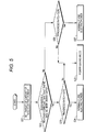
- the control of the third embodiment performed by the control unit 13 will be described with reference to a flowchart in Fig. 5 .
- Step S21 the target value of the amount of sold electric power is set.
- the target value of each month is automatically set or set by a user's operation.
- the target value is appropriately set by considering variation of daylight hours, the number of family members, and the like.
- Step S22 it is determined whether or not there will be many sunny days based on a weekly weather forecast.
- the control unit 13 transmits position information to a predetermined site through the Internet 15 and acquires information of the weekly weather forecast from the predetermined site. It is possible to estimate a rate of sunny days from the weekly weather forecast. For example, when the rate of sunny days in a week is 50% or more, it is estimated that there will be many sunny days.
- Step S23 if it is determined that there will be many sunny days in step S22, it is determined whether or not the progress rate of the amount of soled electric power with respect to the target value is greater than 100%.
- Step S24 if it is determined that the progress rate is greater than 100% in step S23, the electric power is normally used. In other words, the progress rate is greater than 100% and there will be many sunny days in the coming week, so that it is estimated that the risk that the amount of electric power generation of the photovoltaic power generation system decreases is small. Therefore, the power limitation is not implemented.
- Step S25 if it is determined that the progress rate is smaller thanor equal to 100% in step S23, the power limitation is implemented.
- the power saving mode a power saving mode selected in advance from among the power saving modes A, B, and C is used.
- Step S26 if it is determined that there will be a small number of sunny days according to the weather forecast for this week in step S22, it is determined whether or not the progress rate is greater than 120%.
- Step S27 if it is determined that the progress rate is greater than 120% in step S26, the electric power is normally used. In other words, the rate of sunny days in the coming week is small and there is a risk that the amount of electric power generation of the photovoltaic power generation system decreases, so that the value used for determining whether or not the amount of sold electric power reaches the target is set to higher. When the progress rate is greater than this value, the electric power is normally used.
- step S25 if it is determined that the progress rate is smaller than or equal to 120% in the determination of step S26, the power limitation is implemented in step S25.
- the power saving mode a power saving mode selected in advance from among the power saving modes A, B, and C is used.
- step S5 it is determined whether or not a predetermined period of time, for example, one month has elapsed in the same manner as in the process (step S5) of the first embodiment. If it is determined that the predetermined period of time has not elapsed, the process returns to step S22 (to determine whether or not the weekly weather forecast says that there will be many sunny days). If it is determined that the predetermined period of time has elapsed, the control for one month is completed and the integrated value of the amount of sold electric power is reset. Then, the process of the next month is started.
- the target value of the amount of sold electric power can be set by a user and the power limitation operation is automatically performed so that the amount of sold electric power reaches the target value. Further, the amount of sold electric power in the coming week is estimated by referring to the information of weekly weather forecast. Therefore, in addition to an advantage that the power limitation inwhich the intention of the user is reflected can be implemented in the same manner as in the first embodiment, there is an advantage of improving the prediction accuracy of the amount of sold electric power.
- the units of the amount of sold electric power are not limited to the amount of electric power, but the amount of money of sold electric power may be used.
- the control may be performed so that the amount of saved electric power (the amount of reduced CO2) is the target value.
- a battery may be provided. When a power failure occurs, electric power is supplied to electric apparatuses from the battery. When the remaining capacity of the battery is small, the amount of electric power generated by the photovoltaic power generation system may be used to charge the battery.
- the present disclosure may have the following configurations:
Landscapes
- Engineering & Computer Science (AREA)
- Power Engineering (AREA)
- Physics & Mathematics (AREA)
- General Physics & Mathematics (AREA)
- Automation & Control Theory (AREA)
- General Engineering & Computer Science (AREA)
- Electromagnetism (AREA)
- Radar, Positioning & Navigation (AREA)
- Supply And Distribution Of Alternating Current (AREA)
- Remote Monitoring And Control Of Power-Distribution Networks (AREA)
- Management, Administration, Business Operations System, And Electronic Commerce (AREA)
Applications Claiming Priority (2)
| Application Number | Priority Date | Filing Date | Title |
|---|---|---|---|
| JP2012108152 | 2012-05-10 | ||
| PCT/JP2013/063225 WO2013168814A1 (fr) | 2012-05-10 | 2013-05-02 | Dispositif de gestion de l'énergie, procédé de gestion de l'énergie et programme |
Publications (3)
| Publication Number | Publication Date |
|---|---|
| EP2849302A1 true EP2849302A1 (fr) | 2015-03-18 |
| EP2849302A4 EP2849302A4 (fr) | 2016-01-20 |
| EP2849302B1 EP2849302B1 (fr) | 2018-11-28 |
Family
ID=49550845
Family Applications (1)
| Application Number | Title | Priority Date | Filing Date |
|---|---|---|---|
| EP13788649.5A Not-in-force EP2849302B1 (fr) | 2012-05-10 | 2013-05-02 | Dispositif de gestion de l'énergie, procédé de gestion de l'énergie et programme |
Country Status (5)
| Country | Link |
|---|---|
| US (1) | US20150127181A1 (fr) |
| EP (1) | EP2849302B1 (fr) |
| JP (1) | JPWO2013168814A1 (fr) |
| CN (1) | CN104285353B (fr) |
| WO (1) | WO2013168814A1 (fr) |
Families Citing this family (7)
| Publication number | Priority date | Publication date | Assignee | Title |
|---|---|---|---|---|
| JP2015122831A (ja) * | 2013-12-20 | 2015-07-02 | 三菱電機株式会社 | 電力管理装置および電力管理システム |
| JP5820892B2 (ja) * | 2014-01-09 | 2015-11-24 | 日本電信電話株式会社 | 電力需給制御装置及び電力需給制御方法 |
| US10248146B2 (en) | 2015-10-14 | 2019-04-02 | Honeywell International Inc. | System for dynamic control with interactive visualization to optimize energy consumption |
| JP6745634B2 (ja) * | 2016-04-18 | 2020-08-26 | 三菱電機株式会社 | 消費電力制御装置及び消費電力制御システム |
| JP6740307B2 (ja) * | 2018-03-28 | 2020-08-12 | 赫普科技発展(北京)有限公司 | 電力取引システム |
| EP3716437A1 (fr) * | 2019-03-28 | 2020-09-30 | Siemens Aktiengesellschaft | Procédé et système de surveillance de l'état de fonctionnement des appareils haute tension d'un réseau de distribution d'énergie |
| JP7485465B2 (ja) * | 2021-01-12 | 2024-05-16 | 東芝エネルギーシステムズ株式会社 | 電力制御装置、及び電力制御方法 |
Family Cites Families (14)
| Publication number | Priority date | Publication date | Assignee | Title |
|---|---|---|---|---|
| US4916328A (en) * | 1988-12-08 | 1990-04-10 | Honeywell Inc. | Add/shed load control using anticipatory processes |
| JP2003092844A (ja) | 2001-09-20 | 2003-03-28 | Fujitsu General Ltd | 自家電力供給制御システム |
| JP3889679B2 (ja) * | 2002-06-28 | 2007-03-07 | 三菱電機株式会社 | 電力関連表示装置およびこれを用いた自家発電システム |
| JP2004328960A (ja) | 2003-04-28 | 2004-11-18 | Misawa Homes Co Ltd | 無停電電力供給装置 |
| JP2007510394A (ja) * | 2003-10-24 | 2007-04-19 | スクエア・ディー・カンパニー | インテリジェントな電力管理制御システム |
| CN201523234U (zh) * | 2009-10-20 | 2010-07-07 | 杨琛 | 分区可控式省能设备 |
| CN102097802B (zh) * | 2009-12-10 | 2012-12-26 | 深圳先进技术研究院 | 电能管理系统和电能管理方法 |
| JP5539750B2 (ja) | 2010-02-17 | 2014-07-02 | トヨタホーム株式会社 | 住宅用電力システム |
| JP5782233B2 (ja) | 2010-06-14 | 2015-09-24 | 大和ハウス工業株式会社 | エネルギーマネジメントシステム及びエネルギーマネジメント方法 |
| JP2012019579A (ja) * | 2010-07-06 | 2012-01-26 | Sharp Corp | 電力管理装置、電力管理プログラムおよび記録媒体 |
| JP5602547B2 (ja) * | 2010-08-31 | 2014-10-08 | 積水化学工業株式会社 | 系統連系方法、および系統連系システム |
| US8930037B2 (en) * | 2010-10-01 | 2015-01-06 | General Electric Company | Energy manager with minimum use energy profile |
| WO2012057119A1 (fr) * | 2010-10-27 | 2012-05-03 | 三洋電機株式会社 | Système d'alimentation en électricité |
| JP5580183B2 (ja) * | 2010-12-13 | 2014-08-27 | パナソニック株式会社 | 電力制御装置及びそれを用いた電力制御システム |
-
2013
- 2013-05-02 CN CN201380023269.5A patent/CN104285353B/zh not_active Expired - Fee Related
- 2013-05-02 WO PCT/JP2013/063225 patent/WO2013168814A1/fr not_active Ceased
- 2013-05-02 EP EP13788649.5A patent/EP2849302B1/fr not_active Not-in-force
- 2013-05-02 US US14/398,574 patent/US20150127181A1/en not_active Abandoned
- 2013-05-02 JP JP2014514769A patent/JPWO2013168814A1/ja active Pending
Also Published As
| Publication number | Publication date |
|---|---|
| EP2849302B1 (fr) | 2018-11-28 |
| JPWO2013168814A1 (ja) | 2016-01-07 |
| CN104285353A (zh) | 2015-01-14 |
| WO2013168814A1 (fr) | 2013-11-14 |
| CN104285353B (zh) | 2017-12-26 |
| US20150127181A1 (en) | 2015-05-07 |
| EP2849302A4 (fr) | 2016-01-20 |
Similar Documents
| Publication | Publication Date | Title |
|---|---|---|
| JP7724940B2 (ja) | 動的ナノグリッドを作成し、電力消費者を集合化して、エネルギー市場に参加するシステム及び方法 | |
| US11271400B2 (en) | Power control device, operation plan planning method, and recording medium | |
| EP2849302B1 (fr) | Dispositif de gestion de l'énergie, procédé de gestion de l'énergie et programme | |
| US20190296562A1 (en) | Electrical energy storage system with battery state-of-charge estimation | |
| US10298056B2 (en) | Power control system, power control method, and recording medium | |
| EP2701261A1 (fr) | Dispositif de commande, système de commande électrique et procédé de commande électrique | |
| JP6426922B2 (ja) | 電力システム、御装置及び充放電制御方法 | |
| JPWO2017122243A1 (ja) | 電力供給装置及び制御装置 | |
| US9638545B2 (en) | Power management apparatus, power management system and power management method | |
| US10700524B2 (en) | Management device and control method | |
| CN103283107A (zh) | 电力控制装置 | |
| JP2016015858A (ja) | 電力制御システム、方法及び電力制御装置 | |
| JP6676477B2 (ja) | 建物の消費電力予測システム、蓄電装置の制御システム、及び蓄電装置の制御方法 | |
| US9851734B2 (en) | Alert presentation apparatus and alert presentation method | |
| CN104247193A (zh) | 电力监视装置和电力监视系统 | |
| JP2013106483A (ja) | 電力供給システム | |
| JP6386064B2 (ja) | 電力管理装置、電力管理方法及び電力管理システム | |
| US20140018968A1 (en) | Method for determining and/or controlling an operating time of a consumer coupled to a power station, in particular a photovoltaic power station, and to an energy storage device, and method for operating an energy storage device coupled to a power station | |
| JPWO2017221411A1 (ja) | 制御装置、電力管理システム、充放電の制御方法及びプログラム | |
| JP7706081B1 (ja) | 制御装置、制御方法、及び、プログラム | |
| JP6299514B2 (ja) | 電力供給システム | |
| EP2851690B1 (fr) | Dispositif d'affichage, système d'affichage et procédé d'affichage | |
| WO2024242975A1 (fr) | Moteur d'optimisation intelligent configuré pour être utilisé avec un système de gestion d'énergie | |
| KR20170123008A (ko) | 전기 디바이스의 소비 전력 제어 장치 | |
| JP2016103893A (ja) | 電力管理装置、電力管理方法、及び電力管理用プログラム |
Legal Events
| Date | Code | Title | Description |
|---|---|---|---|
| PUAI | Public reference made under article 153(3) epc to a published international application that has entered the european phase |
Free format text: ORIGINAL CODE: 0009012 |
|
| 17P | Request for examination filed |
Effective date: 20141103 |
|
| AK | Designated contracting states |
Kind code of ref document: A1 Designated state(s): AL AT BE BG CH CY CZ DE DK EE ES FI FR GB GR HR HU IE IS IT LI LT LU LV MC MK MT NL NO PL PT RO RS SE SI SK SM TR |
|
| AX | Request for extension of the european patent |
Extension state: BA ME |
|
| DAX | Request for extension of the european patent (deleted) | ||
| D17D | Deferred search report published (deleted) | ||
| RA4 | Supplementary search report drawn up and despatched (corrected) |
Effective date: 20151221 |
|
| RIC1 | Information provided on ipc code assigned before grant |
Ipc: H02J 3/46 20060101ALI20151215BHEP Ipc: H02J 3/00 20060101AFI20151215BHEP |
|
| STAA | Information on the status of an ep patent application or granted ep patent |
Free format text: STATUS: EXAMINATION IS IN PROGRESS |
|
| 17Q | First examination report despatched |
Effective date: 20170720 |
|
| GRAP | Despatch of communication of intention to grant a patent |
Free format text: ORIGINAL CODE: EPIDOSNIGR1 |
|
| STAA | Information on the status of an ep patent application or granted ep patent |
Free format text: STATUS: GRANT OF PATENT IS INTENDED |
|
| INTG | Intention to grant announced |
Effective date: 20180622 |
|
| GRAS | Grant fee paid |
Free format text: ORIGINAL CODE: EPIDOSNIGR3 |
|
| GRAA | (expected) grant |
Free format text: ORIGINAL CODE: 0009210 |
|
| STAA | Information on the status of an ep patent application or granted ep patent |
Free format text: STATUS: THE PATENT HAS BEEN GRANTED |
|
| AK | Designated contracting states |
Kind code of ref document: B1 Designated state(s): AL AT BE BG CH CY CZ DE DK EE ES FI FR GB GR HR HU IE IS IT LI LT LU LV MC MK MT NL NO PL PT RO RS SE SI SK SM TR |
|
| REG | Reference to a national code |
Ref country code: CH Ref legal event code: EP |
|
| REG | Reference to a national code |
Ref country code: AT Ref legal event code: REF Ref document number: 1071360 Country of ref document: AT Kind code of ref document: T Effective date: 20181215 |
|
| REG | Reference to a national code |
Ref country code: IE Ref legal event code: FG4D |
|
| REG | Reference to a national code |
Ref country code: DE Ref legal event code: R096 Ref document number: 602013047508 Country of ref document: DE |
|
| REG | Reference to a national code |
Ref country code: NL Ref legal event code: MP Effective date: 20181128 |
|
| REG | Reference to a national code |
Ref country code: LT Ref legal event code: MG4D |
|
| REG | Reference to a national code |
Ref country code: AT Ref legal event code: MK05 Ref document number: 1071360 Country of ref document: AT Kind code of ref document: T Effective date: 20181128 |
|
| PG25 | Lapsed in a contracting state [announced via postgrant information from national office to epo] |
Ref country code: HR Free format text: LAPSE BECAUSE OF FAILURE TO SUBMIT A TRANSLATION OF THE DESCRIPTION OR TO PAY THE FEE WITHIN THE PRESCRIBED TIME-LIMIT Effective date: 20181128 Ref country code: LT Free format text: LAPSE BECAUSE OF FAILURE TO SUBMIT A TRANSLATION OF THE DESCRIPTION OR TO PAY THE FEE WITHIN THE PRESCRIBED TIME-LIMIT Effective date: 20181128 Ref country code: NO Free format text: LAPSE BECAUSE OF FAILURE TO SUBMIT A TRANSLATION OF THE DESCRIPTION OR TO PAY THE FEE WITHIN THE PRESCRIBED TIME-LIMIT Effective date: 20190228 Ref country code: LV Free format text: LAPSE BECAUSE OF FAILURE TO SUBMIT A TRANSLATION OF THE DESCRIPTION OR TO PAY THE FEE WITHIN THE PRESCRIBED TIME-LIMIT Effective date: 20181128 Ref country code: IS Free format text: LAPSE BECAUSE OF FAILURE TO SUBMIT A TRANSLATION OF THE DESCRIPTION OR TO PAY THE FEE WITHIN THE PRESCRIBED TIME-LIMIT Effective date: 20190328 Ref country code: ES Free format text: LAPSE BECAUSE OF FAILURE TO SUBMIT A TRANSLATION OF THE DESCRIPTION OR TO PAY THE FEE WITHIN THE PRESCRIBED TIME-LIMIT Effective date: 20181128 Ref country code: BG Free format text: LAPSE BECAUSE OF FAILURE TO SUBMIT A TRANSLATION OF THE DESCRIPTION OR TO PAY THE FEE WITHIN THE PRESCRIBED TIME-LIMIT Effective date: 20190228 Ref country code: FI Free format text: LAPSE BECAUSE OF FAILURE TO SUBMIT A TRANSLATION OF THE DESCRIPTION OR TO PAY THE FEE WITHIN THE PRESCRIBED TIME-LIMIT Effective date: 20181128 Ref country code: AT Free format text: LAPSE BECAUSE OF FAILURE TO SUBMIT A TRANSLATION OF THE DESCRIPTION OR TO PAY THE FEE WITHIN THE PRESCRIBED TIME-LIMIT Effective date: 20181128 |
|
| PG25 | Lapsed in a contracting state [announced via postgrant information from national office to epo] |
Ref country code: RS Free format text: LAPSE BECAUSE OF FAILURE TO SUBMIT A TRANSLATION OF THE DESCRIPTION OR TO PAY THE FEE WITHIN THE PRESCRIBED TIME-LIMIT Effective date: 20181128 Ref country code: GR Free format text: LAPSE BECAUSE OF FAILURE TO SUBMIT A TRANSLATION OF THE DESCRIPTION OR TO PAY THE FEE WITHIN THE PRESCRIBED TIME-LIMIT Effective date: 20190301 Ref country code: SE Free format text: LAPSE BECAUSE OF FAILURE TO SUBMIT A TRANSLATION OF THE DESCRIPTION OR TO PAY THE FEE WITHIN THE PRESCRIBED TIME-LIMIT Effective date: 20181128 Ref country code: AL Free format text: LAPSE BECAUSE OF FAILURE TO SUBMIT A TRANSLATION OF THE DESCRIPTION OR TO PAY THE FEE WITHIN THE PRESCRIBED TIME-LIMIT Effective date: 20181128 Ref country code: PT Free format text: LAPSE BECAUSE OF FAILURE TO SUBMIT A TRANSLATION OF THE DESCRIPTION OR TO PAY THE FEE WITHIN THE PRESCRIBED TIME-LIMIT Effective date: 20190328 |
|
| PG25 | Lapsed in a contracting state [announced via postgrant information from national office to epo] |
Ref country code: NL Free format text: LAPSE BECAUSE OF FAILURE TO SUBMIT A TRANSLATION OF THE DESCRIPTION OR TO PAY THE FEE WITHIN THE PRESCRIBED TIME-LIMIT Effective date: 20181128 |
|
| PG25 | Lapsed in a contracting state [announced via postgrant information from national office to epo] |
Ref country code: PL Free format text: LAPSE BECAUSE OF FAILURE TO SUBMIT A TRANSLATION OF THE DESCRIPTION OR TO PAY THE FEE WITHIN THE PRESCRIBED TIME-LIMIT Effective date: 20181128 Ref country code: DK Free format text: LAPSE BECAUSE OF FAILURE TO SUBMIT A TRANSLATION OF THE DESCRIPTION OR TO PAY THE FEE WITHIN THE PRESCRIBED TIME-LIMIT Effective date: 20181128 Ref country code: IT Free format text: LAPSE BECAUSE OF FAILURE TO SUBMIT A TRANSLATION OF THE DESCRIPTION OR TO PAY THE FEE WITHIN THE PRESCRIBED TIME-LIMIT Effective date: 20181128 Ref country code: CZ Free format text: LAPSE BECAUSE OF FAILURE TO SUBMIT A TRANSLATION OF THE DESCRIPTION OR TO PAY THE FEE WITHIN THE PRESCRIBED TIME-LIMIT Effective date: 20181128 |
|
| REG | Reference to a national code |
Ref country code: DE Ref legal event code: R097 Ref document number: 602013047508 Country of ref document: DE |
|
| PG25 | Lapsed in a contracting state [announced via postgrant information from national office to epo] |
Ref country code: SK Free format text: LAPSE BECAUSE OF FAILURE TO SUBMIT A TRANSLATION OF THE DESCRIPTION OR TO PAY THE FEE WITHIN THE PRESCRIBED TIME-LIMIT Effective date: 20181128 Ref country code: RO Free format text: LAPSE BECAUSE OF FAILURE TO SUBMIT A TRANSLATION OF THE DESCRIPTION OR TO PAY THE FEE WITHIN THE PRESCRIBED TIME-LIMIT Effective date: 20181128 Ref country code: EE Free format text: LAPSE BECAUSE OF FAILURE TO SUBMIT A TRANSLATION OF THE DESCRIPTION OR TO PAY THE FEE WITHIN THE PRESCRIBED TIME-LIMIT Effective date: 20181128 Ref country code: SM Free format text: LAPSE BECAUSE OF FAILURE TO SUBMIT A TRANSLATION OF THE DESCRIPTION OR TO PAY THE FEE WITHIN THE PRESCRIBED TIME-LIMIT Effective date: 20181128 |
|
| PLBE | No opposition filed within time limit |
Free format text: ORIGINAL CODE: 0009261 |
|
| STAA | Information on the status of an ep patent application or granted ep patent |
Free format text: STATUS: NO OPPOSITION FILED WITHIN TIME LIMIT |
|
| PG25 | Lapsed in a contracting state [announced via postgrant information from national office to epo] |
Ref country code: SI Free format text: LAPSE BECAUSE OF FAILURE TO SUBMIT A TRANSLATION OF THE DESCRIPTION OR TO PAY THE FEE WITHIN THE PRESCRIBED TIME-LIMIT Effective date: 20181128 |
|
| 26N | No opposition filed |
Effective date: 20190829 |
|
| REG | Reference to a national code |
Ref country code: CH Ref legal event code: PL |
|
| GBPC | Gb: european patent ceased through non-payment of renewal fee |
Effective date: 20190502 |
|
| PG25 | Lapsed in a contracting state [announced via postgrant information from national office to epo] |
Ref country code: CH Free format text: LAPSE BECAUSE OF NON-PAYMENT OF DUE FEES Effective date: 20190531 Ref country code: LI Free format text: LAPSE BECAUSE OF NON-PAYMENT OF DUE FEES Effective date: 20190531 Ref country code: MC Free format text: LAPSE BECAUSE OF FAILURE TO SUBMIT A TRANSLATION OF THE DESCRIPTION OR TO PAY THE FEE WITHIN THE PRESCRIBED TIME-LIMIT Effective date: 20181128 |
|
| REG | Reference to a national code |
Ref country code: BE Ref legal event code: MM Effective date: 20190531 |
|
| PG25 | Lapsed in a contracting state [announced via postgrant information from national office to epo] |
Ref country code: LU Free format text: LAPSE BECAUSE OF NON-PAYMENT OF DUE FEES Effective date: 20190502 |
|
| PG25 | Lapsed in a contracting state [announced via postgrant information from national office to epo] |
Ref country code: TR Free format text: LAPSE BECAUSE OF FAILURE TO SUBMIT A TRANSLATION OF THE DESCRIPTION OR TO PAY THE FEE WITHIN THE PRESCRIBED TIME-LIMIT Effective date: 20181128 |
|
| PG25 | Lapsed in a contracting state [announced via postgrant information from national office to epo] |
Ref country code: GB Free format text: LAPSE BECAUSE OF NON-PAYMENT OF DUE FEES Effective date: 20190502 Ref country code: IE Free format text: LAPSE BECAUSE OF NON-PAYMENT OF DUE FEES Effective date: 20190502 |
|
| PG25 | Lapsed in a contracting state [announced via postgrant information from national office to epo] |
Ref country code: BE Free format text: LAPSE BECAUSE OF NON-PAYMENT OF DUE FEES Effective date: 20190531 |
|
| PG25 | Lapsed in a contracting state [announced via postgrant information from national office to epo] |
Ref country code: FR Free format text: LAPSE BECAUSE OF NON-PAYMENT OF DUE FEES Effective date: 20190531 |
|
| PG25 | Lapsed in a contracting state [announced via postgrant information from national office to epo] |
Ref country code: CY Free format text: LAPSE BECAUSE OF FAILURE TO SUBMIT A TRANSLATION OF THE DESCRIPTION OR TO PAY THE FEE WITHIN THE PRESCRIBED TIME-LIMIT Effective date: 20181128 |
|
| PG25 | Lapsed in a contracting state [announced via postgrant information from national office to epo] |
Ref country code: HU Free format text: LAPSE BECAUSE OF FAILURE TO SUBMIT A TRANSLATION OF THE DESCRIPTION OR TO PAY THE FEE WITHIN THE PRESCRIBED TIME-LIMIT; INVALID AB INITIO Effective date: 20130502 Ref country code: MT Free format text: LAPSE BECAUSE OF FAILURE TO SUBMIT A TRANSLATION OF THE DESCRIPTION OR TO PAY THE FEE WITHIN THE PRESCRIBED TIME-LIMIT Effective date: 20181128 |
|
| PGFP | Annual fee paid to national office [announced via postgrant information from national office to epo] |
Ref country code: DE Payment date: 20210421 Year of fee payment: 9 |
|
| PG25 | Lapsed in a contracting state [announced via postgrant information from national office to epo] |
Ref country code: MK Free format text: LAPSE BECAUSE OF FAILURE TO SUBMIT A TRANSLATION OF THE DESCRIPTION OR TO PAY THE FEE WITHIN THE PRESCRIBED TIME-LIMIT Effective date: 20181128 |
|
| REG | Reference to a national code |
Ref country code: DE Ref legal event code: R119 Ref document number: 602013047508 Country of ref document: DE |
|
| PG25 | Lapsed in a contracting state [announced via postgrant information from national office to epo] |
Ref country code: DE Free format text: LAPSE BECAUSE OF NON-PAYMENT OF DUE FEES Effective date: 20221201 |