EP2849362A1 - Estimation de décalage de fréquence à l'aveugle de signaux impulsionnels - Google Patents
Estimation de décalage de fréquence à l'aveugle de signaux impulsionnels Download PDFInfo
- Publication number
- EP2849362A1 EP2849362A1 EP13306246.3A EP13306246A EP2849362A1 EP 2849362 A1 EP2849362 A1 EP 2849362A1 EP 13306246 A EP13306246 A EP 13306246A EP 2849362 A1 EP2849362 A1 EP 2849362A1
- Authority
- EP
- European Patent Office
- Prior art keywords
- optical signal
- estimation
- frequency offset
- chromatic dispersion
- previous
- Prior art date
- Legal status (The legal status is an assumption and is not a legal conclusion. Google has not performed a legal analysis and makes no representation as to the accuracy of the status listed.)
- Withdrawn
Links
- 230000003287 optical effect Effects 0.000 claims abstract description 75
- 239000006185 dispersion Substances 0.000 claims abstract description 36
- 230000005540 biological transmission Effects 0.000 claims abstract description 19
- 238000012545 processing Methods 0.000 claims abstract description 10
- 238000000034 method Methods 0.000 claims description 21
- 230000003595 spectral effect Effects 0.000 claims description 20
- 238000001228 spectrum Methods 0.000 claims description 16
- 238000004590 computer program Methods 0.000 claims description 2
- 238000013500 data storage Methods 0.000 claims description 2
- 239000013307 optical fiber Substances 0.000 description 5
- 238000011084 recovery Methods 0.000 description 5
- 238000012952 Resampling Methods 0.000 description 2
- 230000000694 effects Effects 0.000 description 2
- 230000001427 coherent effect Effects 0.000 description 1
- 230000003247 decreasing effect Effects 0.000 description 1
- 239000000835 fiber Substances 0.000 description 1
- 230000001939 inductive effect Effects 0.000 description 1
- 238000005259 measurement Methods 0.000 description 1
- 238000012986 modification Methods 0.000 description 1
- 230000004048 modification Effects 0.000 description 1
- 230000010287 polarization Effects 0.000 description 1
- 238000011160 research Methods 0.000 description 1
- 238000007493 shaping process Methods 0.000 description 1
- 238000012546 transfer Methods 0.000 description 1
Images

Classifications
-
- H—ELECTRICITY
- H04—ELECTRIC COMMUNICATION TECHNIQUE
- H04B—TRANSMISSION
- H04B10/00—Transmission systems employing electromagnetic waves other than radio-waves, e.g. infrared, visible or ultraviolet light, or employing corpuscular radiation, e.g. quantum communication
- H04B10/60—Receivers
- H04B10/61—Coherent receivers
- H04B10/616—Details of the electronic signal processing in coherent optical receivers
- H04B10/6164—Estimation or correction of the frequency offset between the received optical signal and the optical local oscillator
-
- H—ELECTRICITY
- H04—ELECTRIC COMMUNICATION TECHNIQUE
- H04B—TRANSMISSION
- H04B10/00—Transmission systems employing electromagnetic waves other than radio-waves, e.g. infrared, visible or ultraviolet light, or employing corpuscular radiation, e.g. quantum communication
- H04B10/60—Receivers
- H04B10/61—Coherent receivers
- H04B10/616—Details of the electronic signal processing in coherent optical receivers
- H04B10/6161—Compensation of chromatic dispersion
-
- H—ELECTRICITY
- H04—ELECTRIC COMMUNICATION TECHNIQUE
- H04B—TRANSMISSION
- H04B10/00—Transmission systems employing electromagnetic waves other than radio-waves, e.g. infrared, visible or ultraviolet light, or employing corpuscular radiation, e.g. quantum communication
- H04B10/60—Receivers
- H04B10/61—Coherent receivers
- H04B10/65—Intradyne, i.e. coherent receivers with a free running local oscillator having a frequency close but not phase-locked to the carrier signal
Definitions
- the invention relates to the reception of optical signal via an optical transmission channel. More precisely, the invention relates to a method of reception when the signal is a pulse-shaped signal.
- the signal may be constituted by different signal components having different frequencies
- the propagation time along the optical fiber depends on the frequencies of the signal components, so that a so-called “chromatic dispersion” occurs and impacts the transmitted optical signal.
- the chromatic dispersion is usually evaluated for cancelling, or at least reducing, its effects and, then enable the receiver to detect and decode the transmitted signal.
- Chromatic dispersion can be compensated by using linear filter in the time domain, according to an estimation of its value than can be done by several methods known in the art.
- the chromatic dispersion is determined by determining two complex discrete frequency components, with frequencies spaced by the symbol rate of the optical signal, and then determining a phase value based on these components and then the chromatic dispersion from this phase value.
- Another technique that has been proposed recently for increasing further the transmission capacity of optical fibers consists in reducing the frequency spectral footprint of each individual transmitted signal components.
- Pulse-shaped signal components are of particular interest because they allow increasing the information spectral density (ISD) without inducing inter-symbol interference (ISI) according to the Nyquist ISI criterion.
- ISD information spectral density
- ISI inter-symbol interference
- the object of the present invention is to allow implementing this chromatic dispersion compensation in the context of transmitted signals which are Nyquist pulse-shaped.
- This object is achieved with a method of detecting an optical signal, comprising steps of Receiving an optical signal transmitted via an optical transmission channel; Determining an estimation of a chromatic dispersion of said optical transmission channel; and compensating said optical signal for said chromatic dispersion on the basis of said estimation; Wherein a frequency offset is determined and said optical signal is compensated for said frequency offset before said step of determining an estimation of a chromatic dispersion
- Preferred embodiments comprise one or more of the following features, which can be taken separately or together, either in partial combination or in full combination.
- Another aspect of the invention is a computer program product comprising computer-executable instructions for performing a method as previously described, when the program is run on a computer.
- Another aspect of the invention is a digital data storage medium encoding a machine-executable program of instructions to perform a method as previously described.
- Another aspect of the invention concerns a receiver for detecting an optical signal, comprising a processing chain being adapted for Receiving an optical signal transmitted via an optical transmission channel; Determining an estimation of a chromatic dispersion of said optical transmission channel; and compensating said optical signal for said chromatic dispersion on the basis of said estimation; And being further adapted to determine a frequency offset and to compensate said optical signal for said frequency offset before the determination of said estimation of said chromatic dispersion.
- Preferred embodiments comprise one or more of the following features, which can be taken separately or together, either in partial combination or in full combination.
- Another aspect of the invention concerns an optical transmission system comprising at least a receiver as previously described.
- An optical system is typically made of an emitter transmitting an optical signal by a laser to a receiver through an optical channel like an optical fiber. Before the received signal being usable, it should be processed by the receiver to take into account the channel's transfer function, compensate for chromatic dispersion, recover the frequency offset, etc.
- FIG. 1 shows a possible and non-limitative signal processing chain at the receiver end.
- This chain is here implemented by a digital signal processor (DSP). It can be understood that it can be provided by dedicated hardware as well as hardware capable of executing software in association with appropriate software.
- DSP digital signal processor
- the functions, given below, can be provided by a single dedicated processor, or by a plurality of processors.
- the signal flows through a coherent mixer (P1), and then through a set of successive circuitries: deskewing and resampling (P2) of the signal, chromatic dispersion (CD) estimation and compensation (P3), Timing recovery (P4), Polarization demultiplexing (P5), Frequency Offset Recovery (P6), Carrier Phase Recovery (P7).
- P1 coherent mixer
- P2 deskewing and resampling
- CD chromatic dispersion
- P3 Timing recovery
- P5 Polarization demultiplexing
- P6 Frequency Offset Recovery
- Carrier Phase Recovery P7
- FIG. 2a depicts the frequency spectrum of a possible signal transmitted over the optical fiber.
- B represents the baudrate or symbol rate.
- the chromatic dispersion can be estimated on the basis of two complex discrete frequency components, with frequencies spaced by the symbol rate B. These two components are depicted as two frequency bands: a lower band and an upper band at, respectively -B/2 and +B/2.
- phase value can be determined, on the basis of which the chromatic dispersion can be determined.
- FIG. 2b depicts a Nyquist pulse-shaped signal.
- the pulse-shaped signal has the advantage of having a reduced frequency spectrum.
- the optical channel has a limited frequency bandwidth, the more reduced is the spectrum for each transmitted optical signals, the more signals can be transmitted on the same time window. This propriety can of course be used to increase the capacity of the optical transmission channel.
- the signal represented on figure 2b has a roll-off factor ⁇ .
- This roll-off factor implies an excess bandwidth of the signal beyond the baud-rate B. Therefore, the full bandwidth of the signal becomes (1+ ⁇ ) ⁇ B.
- the roll-off factor ⁇ equals to zero, the pulse-shaped signal becomes a square signal. In practice, the roll-off factor is not equal to zero but is small, for instance, ⁇ 0.2.
- a frequency offset can appear.
- the value of the frequency offset is not known by the receiver can determine it in a blind way or by the use of special data transmitted over the channel. Blind estimation of the frequency offset is preferable as it does not impact the payload of the transmitted data and is independent of the modulation scheme for transmitting the data.
- frequency offset depends on the physical characteristics of the optical transmission channel. It typically ranges between +2GHz and -2GHz. It is usually below ⁇ 3GHz.
- the processing of the received optical signal comprises, at step P3, the determination of the chromatic dispersion implied by the optical transmission channel, and the compensation of the optical signal on the basis of this estimation.
- an estimation of the chromatic dispersion can be determined on the basis of a phase value, itself determined from the upper and lower bands at, respectively -B/2 and +B/2, wherein B is the baudrate of the received optical signal.
- the presence of the frequency offset does not involve any particular problem.
- the footprint of the Nyquist pulse-shaped signal is equal to (1+ ⁇ ) ⁇ B.
- the energy (i.e. quantity of information) at frequencies below -B/2 and above +B/2 are dramatically reduced and even negligible.
- the presence of the frequency offset shifts the signal spectrum, so that one of the bands (here the upper band at +B/2) falls partially out of the footprint.
- the more important is the frequency offset the less the band overlaps the signal spectrum. In the worst case, there is not overlap, so that one of the bands contains no energy. In general case, the overlap is small, depending on the size of the bands, and the energy of the signal within one of the band is low.
- step P6 of Frequency Offset Recovery depicted on figure 1 can still be implemented to provide a fine-grained estimation and recovery, which can be useful for the subsequent treatment of the optical signal.
- the additional proposed steps are sufficient to compensate for the frequency offset so that the chromatic dispersion can be well estimated and compensated.
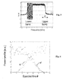
- the frequency offset is determined by comparing spectral values of the received optical signal at two frequency bands around -B/2 and +B/2 of the center of the spectrum of the signal, wherein B represents the baudrate of this optical signal.
- This embodiment exploits the property of the Nyquist pulse shaping that implies an important slope modification of the magnitude of the spectral components around the clock tone (i.e. center of the clock tone) ⁇ B/2.
- FIG. 3 illustrates such a spectrum for an experimental example. It shows the signal in dB according to the frequency indicated as offset from the clock tone (corresponding to 0) and expressed in GHz.
- the width ⁇ f of the upper and lower bands can be set as a parameter of the processing step. Its value can be preset according to the maximum expected frequency offset. As earlier said, this maximum expected frequency offset can be around 3GHz.
- the values of S + and S - can be mean values determined from values taken on several measurement intervals. This embodiment provides the advantage of decreasing the influence of the noise.
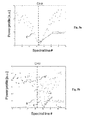
- FIG. 4 shows the power profile for these two functions according to the spectral lines within the bands.
- the number of spectral lines depends on the size of the FFT (Fast Fourier Transform) applied to the optical signal; and, consequently, the accuracy of the estimation of the frequency offset depends on this size of the FFT.
- the accuracy can be 12 MHz, which is sufficient for the next step consisting the estimating and compensating the chromatic dispersion.
- the figure 5b shows, in addition to the cost function C, the two functions S + , S - .
- the optimal value providing the estimation for the frequency offset is the minimal value of this cost function C.
- the figure 5a shows clearly a minimal value at 125 MHz (i.e. one spectral line to the right of the 0 Hz vertical line).
- the figure 5b shows a minimal value at 1.125 MHz (i.e. 9 spectral lines to the right of the 0 MHz spectral line).
Landscapes
- Physics & Mathematics (AREA)
- Electromagnetism (AREA)
- Engineering & Computer Science (AREA)
- Computer Networks & Wireless Communication (AREA)
- Signal Processing (AREA)
- Optical Communication System (AREA)
Priority Applications (1)
| Application Number | Priority Date | Filing Date | Title |
|---|---|---|---|
| EP13306246.3A EP2849362A1 (fr) | 2013-09-11 | 2013-09-11 | Estimation de décalage de fréquence à l'aveugle de signaux impulsionnels |
Applications Claiming Priority (1)
| Application Number | Priority Date | Filing Date | Title |
|---|---|---|---|
| EP13306246.3A EP2849362A1 (fr) | 2013-09-11 | 2013-09-11 | Estimation de décalage de fréquence à l'aveugle de signaux impulsionnels |
Publications (1)
| Publication Number | Publication Date |
|---|---|
| EP2849362A1 true EP2849362A1 (fr) | 2015-03-18 |
Family
ID=49293563
Family Applications (1)
| Application Number | Title | Priority Date | Filing Date |
|---|---|---|---|
| EP13306246.3A Withdrawn EP2849362A1 (fr) | 2013-09-11 | 2013-09-11 | Estimation de décalage de fréquence à l'aveugle de signaux impulsionnels |
Country Status (1)
| Country | Link |
|---|---|
| EP (1) | EP2849362A1 (fr) |
Citations (7)
| Publication number | Priority date | Publication date | Assignee | Title |
|---|---|---|---|---|
| US20090142076A1 (en) * | 2007-11-30 | 2009-06-04 | Fujitsu Limited | Frequency offset compensating apparatus and method, and optical coherent receiver |
| WO2010145075A1 (fr) * | 2009-06-17 | 2010-12-23 | Huawei Technologies Co., Ltd. | Procédé de récupération de fréquence porteuse et récepteur optique cohérent intradyne |
| EP2372332A1 (fr) | 2010-03-31 | 2011-10-05 | Alcatel Lucent | Procédé pour déterminer la dispersion chromatique d'un canal optique |
| US20120033965A1 (en) * | 2010-08-06 | 2012-02-09 | Futurewei Technologies, Inc. | Method and Apparatus for Broadband Carrier Frequency and Phase Recovery in Coherent Optical System |
| WO2012100253A2 (fr) * | 2011-01-22 | 2012-07-26 | Viasat, Inc. | Architecture de démodulateur numérique |
| EP2584720A1 (fr) * | 2010-06-17 | 2013-04-24 | Nippon Telegraph And Telephone Corporation | Appareil d'estimation de décalage de fréquence, appareil récepteur, procédé d'estimation de décalage de fréquence et procédé de réception |
| EP2608436A1 (fr) * | 2011-07-26 | 2013-06-26 | Huawei Technologies Co., Ltd. | Procédé et dispositif de réception de signaux optiques multiporteuses |
-
2013
- 2013-09-11 EP EP13306246.3A patent/EP2849362A1/fr not_active Withdrawn
Patent Citations (7)
| Publication number | Priority date | Publication date | Assignee | Title |
|---|---|---|---|---|
| US20090142076A1 (en) * | 2007-11-30 | 2009-06-04 | Fujitsu Limited | Frequency offset compensating apparatus and method, and optical coherent receiver |
| WO2010145075A1 (fr) * | 2009-06-17 | 2010-12-23 | Huawei Technologies Co., Ltd. | Procédé de récupération de fréquence porteuse et récepteur optique cohérent intradyne |
| EP2372332A1 (fr) | 2010-03-31 | 2011-10-05 | Alcatel Lucent | Procédé pour déterminer la dispersion chromatique d'un canal optique |
| EP2584720A1 (fr) * | 2010-06-17 | 2013-04-24 | Nippon Telegraph And Telephone Corporation | Appareil d'estimation de décalage de fréquence, appareil récepteur, procédé d'estimation de décalage de fréquence et procédé de réception |
| US20120033965A1 (en) * | 2010-08-06 | 2012-02-09 | Futurewei Technologies, Inc. | Method and Apparatus for Broadband Carrier Frequency and Phase Recovery in Coherent Optical System |
| WO2012100253A2 (fr) * | 2011-01-22 | 2012-07-26 | Viasat, Inc. | Architecture de démodulateur numérique |
| EP2608436A1 (fr) * | 2011-07-26 | 2013-06-26 | Huawei Technologies Co., Ltd. | Procédé et dispositif de réception de signaux optiques multiporteuses |
Non-Patent Citations (1)
| Title |
|---|
| TADAO NAKAGAWA ET AL: "Wide-range and fast-tracking frequency offset estimator for optical coherent receivers", 36TH EUROPEAN CONFERENCE AND EXHIBITION ON OPTICAL COMMUNICATION : (ECOC 2010) ; TORINO, ITALY, 19 - 23 SEPTEMBER 2010, IEEE, PISCATAWAY, NJ, USA, 19 September 2010 (2010-09-19), pages 1 - 3, XP031789538, ISBN: 978-1-4244-8536-9 * |
Similar Documents
| Publication | Publication Date | Title |
|---|---|---|
| US20170141943A1 (en) | System and method for ofdm symbol receiving and processing | |
| EP2663044B1 (fr) | Procédé, dispositif et système d'estimation de décalage de fréquence de canal | |
| RU2562827C9 (ru) | Система и способ обнаружения вторичного сигнала синхронизации (sss) при сдвиге несущей частоты в нисходящем канале при множественном доступе с ортогональным частотным разделением каналов | |
| CN108512791B (zh) | 基于定时频偏补偿的星载ais解调方法 | |
| KR101376556B1 (ko) | 사이클로스테이션너리 툴박스를 이용하여 잡음에 삽입된텔레비전 신호의 존재 검출 | |
| US10027513B2 (en) | Anti-aliasing channel estimation apparatus and method and receiver | |
| US20130064124A1 (en) | Weak signal detection in wireless communication systems | |
| US10422719B2 (en) | Chromatic dispersion estimating circuit, optical reception device and chromatic dispersion amount estimating method | |
| EP3509230A1 (fr) | Dispositif de compensation de dispersion de longueur d'onde, procédé de compensation de dispersion de longueur d'onde et dispositif de communication | |
| US9258166B2 (en) | Timing synchronization apparatus and method for multi-carrier modulation signals | |
| US7254204B2 (en) | Method and system for OFDM symbol timing synchronization | |
| US8682182B2 (en) | Blind carrier frequency offset detection for coherent receivers using quadrature amplitude modulation formats | |
| US8761326B2 (en) | Compensating devices and methods for detecting and compensating for sampling clock offset | |
| US10652068B2 (en) | Synchronization signal detection | |
| US7792202B2 (en) | Apparatus and method for estimating timing offset of OFDM symbol, and method of recovering symbol timing of OFDM symbol | |
| WO2015035922A1 (fr) | Dispositif et procédé pour éliminer une interférence à bande étroite d'un système de communications par ligne électrique | |
| EP2849362A1 (fr) | Estimation de décalage de fréquence à l'aveugle de signaux impulsionnels | |
| CN101267244B (zh) | 定时跟踪方法 | |
| EP2372332B1 (fr) | Procédé pour déterminer la dispersion chromatique d'un canal optique | |
| US9973368B2 (en) | Fine timing | |
| JP5646372B2 (ja) | 受信装置及び信号判定プログラム | |
| CN102307164B (zh) | 数字频率估计方法及系统 | |
| CN102904843B (zh) | 频偏估计的方法及装置 | |
| EP4344095A1 (fr) | Dispositif d'estimation de guide d'ondes, procédé d'estimation de guide d'ondes et programme | |
| US8238492B2 (en) | Method and apparatus for packet detection via cross-correlation in the presence of frequency offset |
Legal Events
| Date | Code | Title | Description |
|---|---|---|---|
| PUAI | Public reference made under article 153(3) epc to a published international application that has entered the european phase |
Free format text: ORIGINAL CODE: 0009012 |
|
| 17P | Request for examination filed |
Effective date: 20130911 |
|
| AK | Designated contracting states |
Kind code of ref document: A1 Designated state(s): AL AT BE BG CH CY CZ DE DK EE ES FI FR GB GR HR HU IE IS IT LI LT LU LV MC MK MT NL NO PL PT RO RS SE SI SK SM TR |
|
| AX | Request for extension of the european patent |
Extension state: BA ME |
|
| STAA | Information on the status of an ep patent application or granted ep patent |
Free format text: STATUS: THE APPLICATION IS DEEMED TO BE WITHDRAWN |
|
| 18D | Application deemed to be withdrawn |
Effective date: 20150919 |