EP2849397A1 - Système de communication, dispositif de commande, procédé de communication, et programme - Google Patents
Système de communication, dispositif de commande, procédé de communication, et programme Download PDFInfo
- Publication number
- EP2849397A1 EP2849397A1 EP20130786966 EP13786966A EP2849397A1 EP 2849397 A1 EP2849397 A1 EP 2849397A1 EP 20130786966 EP20130786966 EP 20130786966 EP 13786966 A EP13786966 A EP 13786966A EP 2849397 A1 EP2849397 A1 EP 2849397A1
- Authority
- EP
- European Patent Office
- Prior art keywords
- forwarding node
- broadcast
- multicast
- domains
- forwarding
- Prior art date
- Legal status (The legal status is an assumption and is not a legal conclusion. Google has not performed a legal analysis and makes no representation as to the accuracy of the status listed.)
- Withdrawn
Links
Images







Classifications
-
- H—ELECTRICITY
- H04—ELECTRIC COMMUNICATION TECHNIQUE
- H04L—TRANSMISSION OF DIGITAL INFORMATION, e.g. TELEGRAPHIC COMMUNICATION
- H04L65/00—Network arrangements, protocols or services for supporting real-time applications in data packet communication
- H04L65/60—Network streaming of media packets
- H04L65/61—Network streaming of media packets for supporting one-way streaming services, e.g. Internet radio
- H04L65/611—Network streaming of media packets for supporting one-way streaming services, e.g. Internet radio for multicast or broadcast
-
- H—ELECTRICITY
- H04—ELECTRIC COMMUNICATION TECHNIQUE
- H04L—TRANSMISSION OF DIGITAL INFORMATION, e.g. TELEGRAPHIC COMMUNICATION
- H04L12/00—Data switching networks
- H04L12/28—Data switching networks characterised by path configuration, e.g. LAN [Local Area Networks] or WAN [Wide Area Networks]
- H04L12/46—Interconnection of networks
- H04L12/4641—Virtual LANs, VLANs, e.g. virtual private networks [VPN]
-
- H—ELECTRICITY
- H04—ELECTRIC COMMUNICATION TECHNIQUE
- H04L—TRANSMISSION OF DIGITAL INFORMATION, e.g. TELEGRAPHIC COMMUNICATION
- H04L69/00—Network arrangements, protocols or services independent of the application payload and not provided for in the other groups of this subclass
- H04L69/22—Parsing or analysis of headers
-
- H—ELECTRICITY
- H04—ELECTRIC COMMUNICATION TECHNIQUE
- H04L—TRANSMISSION OF DIGITAL INFORMATION, e.g. TELEGRAPHIC COMMUNICATION
- H04L49/00—Packet switching elements
- H04L49/20—Support for services
- H04L49/201—Multicast operation; Broadcast operation
Definitions
- the present invention relates to a communication system, a control apparatus, a communication method and a program, and in particular to a communication system, a control apparatus, a communication method and a program, which realize communication by forwarding nodes that forward received packets and the control apparatus that controls the forwarding nodes.
- Patent Literatures 1 to 4 disclose methods of broadcasting or multicasting in a virtual network.
- Patent Literature 1 discloses a method of assigning an address of a carrier virtual Local Area Network (CVLAN) for a layer 2 network (below, "L2NW”) for each physical port and VLAN, and assigning a broadcast or multicast address to each CVLAN, to realize broadcasting/multicasting.
- CVLAN carrier virtual Local Area Network
- L2NW layer 2 network
- Patent Literature 2 there is provided a virtual hub that learns and stores relationships between a source MAC address inside a user MAC header in a received packet, and a terminal-side virtual interface through which the packet passes; and there is a disclosure of a packet routing method that uses an access router, which forwards the packet based on this stored information, and, on a network side, adds a VPN number, performs encapsulation in an IP packet and carries out transmission.
- broadcasting is realized by setting up a server for broadcasting, known as a packet copy server, and copying and forwarding to another access router within the same VPN (refer to paragraph 0122, seventh exemplary embodiment).
- Patent Literature 3 discloses a node that adds an extension tag including forwarding information to a node on an exit side, to an input data frame, and performs forwarding. There is a description that when performing broadcasting, by setting forwarding information of a node on an input side (for example, a source MAC address) in the extension tag, data frames are relayed (claim 3, paragraphs 0129 and 0137).
- Patent Literature 4 discloses a method of switching a packet by a transmission medium provided with a plurality of terminals connected using different links.
- the same literature has a description of preventing packet loops, by using an identifier list (broadcast control information) linked 1-to-1 with a switch through which frames pass (paragraphs 0038 to 0040).
- Non-Patent Literatures 1 and 2 disclose a network in which communication is taken as end-to-end flow, and which includes switches called “OpenFlow switches” that process flows thereof, and a controller that sets control information known as “flow entries” for the switches.
- a VLAN header defined by IEEE 802.1 has a length of 12 bits, and there is a problem in that the number of VLANs that can be identified is limited to 4,096.
- Non-Patent Literatures 1 and 2 by performing conversion of VLAN IDs of input or output packets with regard to outside a network in accordance with a flow entry in a switch located at an edge, it is possible to increase the number of VLANs that can be handled by the network to 4,096 or more.
- broadcast or multicast flow entries in an OpenFlow network as shown in FIG. 16 may be considered. Accordingly, in order to implement a spanning tree requiring that broadcast or multicast packets do not loop, as shown in FIG. 17 , broadcast or multicast flow entries (referred to below as "BCMC base flow entries,” with reference symbols 400A to 400C attached) that do not depend on VLAN ID, are set in each forwarding node.
- BCMC base flow entries broadcast or multicast flow entries
- FIG. 18 to FIG. 20 are examples of BCMC base flow entries 400A to 400C to be set in respective forwarding nodes of FIG. 17 , and setting is performed with regard to flow entries corresponding to arrows in FIG. 17 and flow entries to drop packets that could loop.
- BCMC base flow entries 400A to 400C it is possible to cope with the problem of an increase in the number of flow entries for each broadcast or multicast domain.
- a forwarding node located at an edge of the network does not perform conversion of VLAN ID of input or output packets with regard to an outside network, but processes packets using a VLAN setting for ports of the relevant forwarding node as in the following, for example.
- a forwarding node located at the edge receives a packet in a state in which the set VLAN ID from the port in question is tagged only in a case where the input packet is untagged, and performs processing to drop the input packet at the port in question in a case where the input packet is tagged.
- a forwarding node located at the edge receives a packet in a state in which the VLAN ID from the port in question is tagged only in a case where the VLAN ID of the input packet is the same, and performs processing to drop the input packet at the port in question in a case where the input packet is untagged or has a different VLAN ID.
- a forwarding node located at the edge In a case where a VLAN ID is set with a port being untagged, a forwarding node located at the edge outputs a packet in a state in which the VLAN ID is untagged from the port in question only in a case where the VLAN ID of the output packet is the same, and performs processing to drop the output packet at the port in question in a case where the VLAN ID is different.
- a forwarding node located at the edge outputs a packet in a state in which the VLAN ID is tagged from the port in question only in a case where the VLAN ID of the output packet is the same, and performs processing to drop the output packet at the port in question where the VLAN ID is different.
- a broadcast or multicast domain in the OpenFlow network in this case is, for example, a combination of a virtual L2SW 502A and external NW endpoints 503A and 503B of a virtual network 500A shown in FIG. 21
- the same VLAN ID is used in the same broadcast domain or multicast domain, as in a combination of a virtual L2SW 502B and external NW endpoints 503C to 503E.
- the external NW endpoint 503A in FIG. 21 indicates that the port to which an external node 300A of a forwarding node 200A is connected in FIG. 17 , is untagged, and the VLAN ID is 10.
- the external NW endpoint 503C indicates that the port to which an external node 300C of a forwarding node 200B is connected in FIG. 17 , is tagged and the VLAN ID is 20.
- the external NW endpoint 503D indicates that the port to which an external node 300D of a forwarding node 200C is connected in FIG. 17 , is tagged and the VLAN ID is 20, and the external NW endpoint 503E indicates that the port to which an external node 300E of a forwarding node 200C is connected in FIG. 17 , is tagged and the VLAN ID is 20.
- Non-Patent Literatures 1 and 2 if a broadcast or a multicast is implemented, there is a problem in that either an increase in flow entries or a limitation to the number of VLANs becomes a constraint.
- Patent Literature 1 it is possible to handle VLANs exceeding the upper limit of 4,096 in the number of VLANs as described above, but since a broadcast or multicast address is assigned for each CVLAN, it is necessary to have a huge number of entries, similar to the abovementioned OpenFlow network.
- Patent Literature 2 besides a broadcast server, known as a packet copy server, being necessary, corresponding traffic is generated between an IP network and the packet copy server.
- Patent Literature 3 since a source MAC address is set in a forwarding tag, there is a possibility of the number of entries becoming very large, in the same way as the method of Patent Literature 1.
- a communication system comprising: a control apparatus that sets broadcast domains or multicast domains respectively for virtual networks configured in a physical network including a forwarding node(s), and sets, in the forwarding node(s), broadcast or multicast control information, associating a packet forwarding destination and a match condition including an identifier for identifying one of the broadcast domains or multicast domains; and the forwarding node(s) that performs a broadcast or multicast using the broadcast or multicast control information.
- a control apparatus that sets broadcast domains or multicast domains respectively for virtual networks configured in a physical network including a forwarding node(s), and sets, in the forwarding node(s), broadcast or multicast control information associating a packet forwarding destination and a match condition including an identifier for identifying one of the set broadcast domains or multicast domains.
- a communication method comprises: setting broadcast domains or multicast domains respectively for virtual networks configured in a physical network including a forwarding node(s); setting, in the forwarding node(s), broadcast or multicast control information associating a packet forwarding destination and a match condition including an identifier for identifying one of the broadcast domains or multicast domains; and causing the forwarding node(s) to execute a broadcast or multicast using the broadcast or multicast control information.
- This method is associated with a particular machine known as a computer, which controls forwarding nodes.
- a program that causes a computer, configuring a control apparatus that sets control information in a forwarding node(s), to execute: setting broadcast domains or multicast domains respectively for virtual networks configured in a physical network including the forwarding node(s); and setting, in the forwarding node(s), broadcast or multicast control information associating a packet forwarding destination and a match condition including an identifier for identifying the broadcast domains or multicast domains.
- This program may be recorded on a computer-readable (non-transient) storage medium. That is, the present invention may be embodied as a computer program product.
- Non-Patent Literatures 1 and 2 it is possible to implement in the OpenFlow network of Non-Patent Literatures 1 and 2 a broadcast or a multicast without being constrained by the number of VLAN IDs, and with fewer flow entries.
- the present invention in an exemplary embodiment thereof, can be implemented by a configuration comprising: a control apparatus 100 that sets control information for a broadcast or multicast in forwarding nodes 200A to 200C, and the forwarding nodes 200A to 200C that perform a broadcast or multicast using the broadcast or multicast control information, as shown in FIG. 1 .
- control apparatus 100 sets broadcast domains or multicast domains respectively for virtual networks configured in a physical network including the forwarding nodes 200A to 200C (refer to FIG. 3 ), and sets, in the forwarding nodes, broadcast or multicast control information associating a packet forwarding destination and a match condition including an identifier for identifying one of the broadcast domains or multicast domains.
- FIG. 1 is a diagram showing a configuration of the first exemplary embodiment of the present invention.
- a configuration is shown that includes a network configured by a plurality of forwarding nodes 200, and a control apparatus 100 that controls the forwarding nodes 200A to 200C, and realizes communication with external nodes 300A to 300E.
- the forwarding nodes 200A to 200C and the external nodes 300A to 300E are not particularly distinguished, they are denoted "forwarding node 200" and "external node 300,” respectively.
- the control apparatus 100 performs path control for packets between one of the external nodes 300 and another of the external nodes 300 by setting a flow entry for forwarding node(s) 200 in the path.
- the forwarding node 200 searches for a flow entry having a match condition matching the received packet, among flow entries set by the control apparatus 100, and performs processing of the received packet in accordance with the relevant flow entry.
- processing content set in the flow entry forwarding to the external node 300 or another forwarding node 200, outputting to the control apparatus 100, dropping and the like are performed.
- One of the external nodes 300 (for example, external node 300A) transmits a packet addressed to another of the external nodes 300 (for example, external node 300D or external node 300E) to a forwarding node 200, or receives a packet with another of the external nodes 300 as a source, from a forwarding node 200.
- a forwarding node 200 connected to an external node 300 is an "edge forwarding node 200," and a forwarding node 200 connected only to a forwarding node 200 is a core forwarding node.
- An external node 300 need not be directly connected to an edge forwarding node, and may be connected via a legacy apparatus such as an L2SW (Layer 2 Switch) that is not directly controlled by the control apparatus 100; an external node 300 may be an L3SW or a router, and a separate external node 300 may be present ahead of this.
- L2SW Layer 2 Switch
- the present exemplary embodiment also uses BCMC base flow entries as shown in FIG. 17 to FIG. 20 .
- BCMC base flow entries as shown in FIG. 17 to FIG. 20 .
- a flow entry for forwarding between the forwarding nodes 200B and 200C is not set, but this is in order that broadcast and multicast packets are loop-free within the network.
- BCMC path(s) and BCMC base flow entry(ies) are changed.
- a BCMC address is a broadcast or multicast address. For example, in a case of a MAC address, 1 is set in the I/G bit of the first byte.
- FIG. 2 is a block diagram representing a detailed configuration of the control apparatus 100 in the present exemplary embodiment.
- the control apparatus 100 is configured by being provided with: a forwarding node communication unit 101, a forwarding node control unit 102, a virtual network management unit 103, a forwarding node information storage unit 104, a physical network topology storage unit 105, a BCMC base flow entry storage unit 106, a flow entry storage unit 107, a flow storage unit 108, a virtual network topology information storage unit 109, and a virtual node information storage unit 110.
- the forwarding node communication unit 101 relays forwarding node information and input packet information from a forwarding node 200 to the forwarding node control unit 102 or the virtual network management unit 103.
- the forwarding node communication unit 101 refers to the forwarding node information storage unit 104 and relays to a forwarding node 200: output packet information from the virtual network management unit 103, setting instruction(s) with regard to flow entries from the forwarding node control unit 102, request(s) to refer to flow entries, request(s) to refer to forwarding node information from the virtual network management unit 103 and the forwarding node control unit 102, or the like.
- the forwarding node control unit 102 records forwarding node information received via the forwarding node communication unit 101 in the forwarding node information storage unit 104.
- the forwarding node control unit 102 comprehends the network topology, based on information of the forwarding node information storage unit 104 and the input packet information, and updates the network topology information of the physical network topology storage unit 105.
- the forwarding node control unit 102 obtains a path that is to be a base for broadcast and multicast packets, based on the network topology information, and generates a BCMC base flow entry 400 for broadcast and multicast for each forwarding node 200 implementing the path, to be stored in the BCMC base flow entry storage unit 106.
- the forwarding node control unit 102 obtains BCMC flow entries from the BCMC base flow entries, and virtual node information and virtual network topology information from the virtual network management unit 103, to be stored in the flow entry storage unit 107, in addition to setting the flow entries in a forwarding node 200 through the forwarding node communication unit 101. Furthermore, the forwarding node control unit 102 obtains flow entries from flow setting information and network topology information received from the virtual network management unit 103, stores the flow entries in the flow entry storage unit 107, and sets the flow entries in the forwarding node 200 through the forwarding node communication unit 101.
- the virtual network management unit 103 is connected to the virtual node information storage unit 110 that stores virtual node information in a plurality of virtual networks, and the virtual network topology information storage unit 109 that stores connection relationships of virtual nodes for each of a plurality of virtual networks, and manages the virtual networks.
- the virtual network management unit 103 passes the virtual node information and the virtual network topology information to the forwarding node control unit 102.
- the virtual network management unit 103 On receiving input packet information from the forwarding node 200 via the forwarding node communication unit 101, the virtual network management unit 103 processes the input packet information based on the virtual network topology information. More specifically, the virtual network management unit 103 performs processing such as dropping input packet information, reception by virtual nodes such as a virtual L3SW (refer to virtual L3SW 501A of FIG. 3 ), output of output packet information from virtual nodes such as an external NW endpoint (refer to external NW endpoints 503A to 503E), based on input packet information and information of the abovementioned virtual node information storage unit 110 and the virtual network topology information storage unit 109.
- processing such as dropping input packet information, reception by virtual nodes such as a virtual L3SW (refer to virtual L3SW 501A of FIG. 3 ), output of output packet information from virtual nodes such as an external NW endpoint (refer to external NW endpoints 503A to 503E), based on input packet information and information of the abovementi
- output of the output packet information is performed not only on receipt of input packet information from the forwarding node communication unit 101, but also at host transmission of a virtual node such as a virtual L3SW (refer to virtual L3SW 501A of FIG. 3 ).
- the virtual network management unit 103 outputs the output packet information to the forwarding node 200 through the forwarding node communication unit 101.
- the virtual network management unit 103 may make a request, to the forwarding node control unit 102, for flow setting according to flow setting information based on: input packet information from the forwarding node communication unit 101 and drop information corresponding thereto, or input packet information from the forwarding node communication unit 101 and output of the output packet information to the forwarding node communication unit 101 corresponding thereto. It is to be noted that it is also possible for the virtual network management unit 103 to make a flow setting request to the forwarding node control unit 102 from the virtual network topology information or the like.
- the forwarding node information storage unit 104 stores information of each of the forwarding nodes 200.
- forwarding node port information As information stored in the forwarding node information storage unit 104, forwarding node port information, VLAN setting information, forwarding node performance, and addresses for accessing forwarding nodes, for example, may be cited. In addition to this, statistical information or the like may be included.
- the physical network topology storage unit 105 stores network topology information representing connection relationships among the forwarding nodes 200.
- the BCMC base flow entry storage unit 106 holds flow entries for respective forwarding nodes 200 as a basis for broadcast or multicast flow in the network. For example, in a case where a broadcast or multicast flow is set among the forwarding nodes 200A to 200C as shown by arrows in FIG. 17 , the BCMC base flow entry storage unit 106 stores BCMC base flow entries of FIG. 18 to FIG. 20 generated in correspondence thereto.
- the flow entry storage unit 107 stores flow entries set in the forwarding nodes 200.
- the flow storage unit 108 stores flow setting information such as processing and path determined for each flow.
- the flow setting information includes, for example, information of match conditions for identifying flows, states of packets when outputted from a flow termination point in a network, external NW endpoints when a packet is inputted to a network (refer to external NW endpoints 503A to 503E of FIG. 3 ), external NW endpoints when outputted (refer to external NW endpoints 503A to 503E of FIG. 3 ), and the like.
- the virtual network topology information storage unit 109 holds information of connections among virtual nodes for each virtual network 500A.
- the virtual node information storage unit 110 stores virtual node information such as that of a virtual L3SW (refer to virtual L3SW 501A of FIG. 3 ) or a virtual L2SW (refer to virtual L2SW 502A and 502B of FIG. 3 ), and external NW endpoints (external NW endpoints 503A to 503E of FIG. 3 ), for each virtual network.
- the virtual node information concerns, for example, for a case of a virtual L3SW (refer to virtual L3SW 501A of FIG. 3 ), information similar to that of an L3SW such as virtual interface information, routing table information, ARP (Address Resolution Protocol) entry information, and the like, and relationships with the virtual network 500A.
- virtual L2SW 502A and 502B in FIG. 3 information similar to that of an L2SW such as virtual interface information or entry information of a MAC forwarding table, broadcast domain IDs (BC domain IDs) for uniquely distinguishing a broadcast domain, and also relationships with the virtual network 500A are stored.
- an external NW endpoint (refer to external NW endpoints 503A to 503E in FIG. 3 ) information regarding which VLAN IDs have a relationship, and for which ports of which forwarding nodes 200 in the network managed by the control apparatus 100, and also relationships with the virtual network 500A are stored.
- VLAN ID information of external NW endpoints (refer to external NW endpoints 503A to 503E in FIG. 3 ) is untagged or tagged; if untagged, whether or not a VLAN ID for untagged use is to be used; if used, which VLAN ID; and if tagged, which VLAN ID.
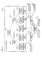
- FIG. 3 shows an example of a virtual network provided according to the control apparatus 100 of the present exemplary embodiment.
- the virtual L3SW 501A, virtual L2SW 502A and 502B, and external NW endpoints 503A to 503E are present as virtual nodes in the virtual network 500A; the virtual L3SW 501A and virtual L2SW 502A and 502B are connected as virtual network topology; the virtual L2SW 502A and external NW endpoints 503A and 503B are connected; and virtual L2SW 502B and external NW endpoints 503C to 503E are connected.
- the virtual L2SW 502A has 1 as a BC domain ID, and the virtual L2SW 502 has 2 as a BC domain ID. It is to be noted that it is sufficient if assignment of a BC domain ID is such that the virtual network management unit 103 can uniquely identify the virtual L2SW 502.
- the virtual network 500A corresponds to the physical network of FIG. 1 , as shown in FIG. 4 (dashed lines in FIG. 4 indicate correspondence relationships between physical and virtual);
- the external NW endpoint 503A corresponds to an untagged port with a VLAN ID of 10 at an external node 300A connection port of the forwarding node 200A.
- the external NW endpoint 503B corresponds to a tagged port with a VLAN ID of 20 at the external node 300B connection port of the forwarding node 200B; and the external NW endpoint 503C corresponds to a tagged port with a VLAN ID of 30 at the external node 300C connection port of the forwarding node 200B.
- the external NW endpoint 503D corresponds to a tagged port with a VLAN ID of 20 at the external node 300D connection port of the forwarding node 200C; and the external NW endpoint 503E corresponds to a tagged port with a VLAN ID of 20 at the external node 300E connection port of the forwarding node 200C.
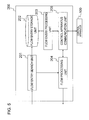
- FIG. 5 is a block diagram showing a detailed configuration of a forwarding node 200.
- the forwarding node 200 is configured by being provided with a flow entry search unit 201, a flow entry storage unit 202, a flow entry processing unit 203, a flow processing unit 204, and a control apparatus communication unit 205.
- the flow entry search unit 201 extracts flow entry search condition information in order to search for a flow entry from received packets, and searches the flow entry storage unit 202 using the flow entry search condition information. As a result of the search if there is a matching flow entry, the flow entry search unit 201 updates timeout time and statistical information thereof.
- the flow entry search unit 201 passes processing content (instruction or action set) determined in the matching flow entry, and the input packet to the flow processing unit 204.
- the flow entry storage unit 202 holds a flow entry that has been set by the forwarding node control unit 102 of the control apparatus 100.
- the flow entry held by the flow entry storage unit 202 is synchronized with a flow entry held in the flow entry storage unit 107 of the control apparatus 100.
- the flow entry processing unit 203 On receiving a reference instruction or a setting instruction such as to add or delete a flow entry from the control apparatus 100 through the control apparatus communication unit 205, the flow entry processing unit 203 performs the relevant processing on the flow entry storage unit 202.
- the flow entry processing unit 203 refers to the flow entry storage unit 202, deletes flow entries that have timed out, and notifies the control apparatus 100 that the flow entries in question have been deleted, through the control apparatus communication unit 205.
- the flow processing unit 204 processes packets in accordance with processing content to be applied to an input packet passed from the flow entry search unit 201 or the control apparatus 100. Specifically, modification of packet header information, forwarding to an external node 300 or another forwarding node 200, outputting to the control apparatus 100, dropping, and the like are performed.
- the control apparatus communication unit 205 relays between the control apparatus 100, and the flow entry processing unit 203 or the flow processing unit 204.
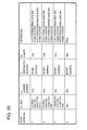
- FIG. 6 to FIG. 8 show examples of BCMC base flow entries respectively set in the forwarding nodes 200A to 200C, in order to perform a broadcast or a multicast, in the virtual network 500A of FIG. 3 .
- FIG. 6 to FIG. 8 in a case where two tables are used and the forwarding node receives a packet from an external node 300, pipeline processing is performed, making reference to the second table (Table #2) in accordance with an instruction of the first table (Table #1) (refer to "4.1.1 Pipeline Processing" of Non-Patent Literature 2).
- FIG. 6 to FIG. 8 are merely examples; there may be 1 or more flow tables, and the flow entries also may be divided.
- the forwarding node 200 performs processing indicated in (1) and (2) below, based on VLAN setting information that has been set in the relevant port.
- an MPLS label is a BC domain ID, and this information forms a match condition for flow entries.
- the MPLS label is 20 bits, it is possible to handle VLANs of 2 ⁇ 20 (1,048,576) in number for a broadcast or a multicast. It is to be noted that this method of increasing the number of VLANs is an example, and it is also possible to further increase the number by stacking MPLS Shim headers for BC domain IDs.
- VLAN header(s) may be deleted at the same time as when MPLS Shim headers are inserted (in this case, VLAN header(s) may be inserted (restored) at a time of deletion of MPLS Shim headers at a network exit). It is also possible to encapsulate packets with a VLAN header or MAC header and to apply a BC domain ID to a source address in an external MAC address; and it is also possible to encapsulate packets with a MPLS Shim header and to apply a BC domain ID to an MPLS label.
- BCMC flow entries in FIG. 6 to FIG. 8 are examples, and there is no problem in adding "forwarding node 200C connection port output" to an instruction of flow entry No. 1 in the second flow table (Table #2) in FIG. 6 , as in BCMC base flow entries in FIG. 18 to FIG. 20 .
- there is no problem in adding "external node 300C connection port output” to an instruction of flow entry No. 3 in the first flow table (Table #1) in FIG. 7 since the VLAN setting of a port of the forwarding node 200B is used; and there is no problem in adding "external node 300B connection port output" to an instruction of flow entry No. 1 in the first flow table (Table #1) in FIG.
- VLAN setting of a port of the forwarding node 200B since the VLAN setting of a port of the forwarding node 200B is used.
- a packet may be received in an untagged state from the port in question only in a case where the input packet is untagged, and in a case where the input packet is tagged, processing may be performed to drop the input packet at the port in question.
- processing is performed to drop the output packet at the port in question when tagged, as examples: "modification in VLAN ID 10" by an instruction of flow entry No.
- the abovementioned forwarding node 200 can be implemented as an OpenFlow switch of Non-Patent Literatures 1 and 2.
- the control apparatus 100 can be implemented by adding the abovementioned respective functions, based on an OpenFlow controller of Non-Patent Literatures 1 and 2.
- the respective parts (processing means) of the abovementioned control apparatus 100 can be implemented by a computer program that executes the abovementioned respective processing on a computer configuring the control apparatus 100, using hardware thereof.
- FIG. 9 is a flowchart representing flow of processing to generate the BCMC base flow entries 400 by the control apparatus 100.
- the forwarding node control unit 102 of the control apparatus 100 obtains information of a forwarding node 200 when connected to the forwarding node 200, and stores the information in the forwarding node information storage unit 104 (step S101).
- the forwarding node control unit 102 obtains packets transmitted from the forwarding node 200 to another forwarding node 200 as input packet information from the other forwarding node 200, and by referring to forwarding node information of the forwarding node information storage unit 104, obtains connection information between the forwarding nodes 200 (step S102).
- the forwarding node control unit 102 reflects the connection information between the forwarding nodes 200 in network topology information of the physical network topology storage unit 105.
- the forwarding node control unit 102 obtains a spanning tree such that broadcast or multicast packets are loop-free in the network, based on the network topology information of the physical network topology storage unit 105, and generates a BCMC base flow entry for a broadcast or a multicast, for each forwarding node 200, to be set in the BCMC base flow entry storage unit 106 (step S103).
- FIG. 10 is a flowchart representing flow of processing for setting BCMC flow entries 400 by the control apparatus 100.
- the forwarding node control unit 102 of the control apparatus 100 obtains configuration information of the virtual network, to which BCMC flow entries are set, from the virtual node information storage unit 110 via the virtual network management unit 103 (step S201).
- the forwarding node control unit 102 obtains virtual node information of the virtual L2SW 502 of the virtual network 500A in FIG. 3 , virtual node information of the external NW endpoint 503 that has a connection relationship with the virtual L2SW 502, and virtual network topology information showing connection relationships thereof.
- the forwarding node control unit 102 obtains a BC domain ID corresponding to the obtained virtual node, from the virtual node information storage unit 110 via the virtual network management unit 103.
- the BC domain ID has a sufficient length in order to uniquely distinguish a broadcast domain of the virtual L2SW 502, and has a range larger than a 12 bit VLAN.
- the forwarding node control unit 102 obtains the BCMC base flow entry 400 from the BCMC base flow entry storage unit 106 (step S203).
- the BCMC base flow entry group shown in FIG. 18 to FIG. 20 is obtained.
- the forwarding node control unit 102 uses information obtained in steps S201 to S203 to generate BCMC flow entries realizing the BCMC in the BC domains, and stores these in the flow entry storage unit 107 (step S204). Specifically, a selection is made of the BCMC base flow entries by referring to correspondence relationships of the virtual network and the physical network shown in FIG. 4 , and addition or deletion of a BC domain ID with respect to processing content thereof (instruction), addition of the added BC domain ID to a match condition, or branching to another table, are set. As a result, the BCMC flow entry is generated such that there is a 1-to-1 correspondence relationship between VLAN ID and BC domain ID in the respective forwarding nodes 200.
- the forwarding node control unit 102 sets the generated BCMC flow entry in the forwarding nodes 200 via the forwarding node communication unit 101.
- the BC packet BC packet of the external node 300A received by the forwarding node 200A received from the external NW endpoint 503A in FIG. 3 ( FIG. 4 ), as shown in FIG. 6 , is processed by a flow entry (flow entry No. 1 in Table #1 in FIG. 6 ) that holds an instruction to process BC packets received from the external node 300A corresponding to the external NW endpoint 503A, by the second flow table (Table #2), and a flow entry (flow entry No. 1 in Table #2 in FIG.
- the BC packet (BC packet (VLAN ID 20) of the external node 300B received by the forwarding node 200B) received from the external NW endpoint 503B in FIG. 3 ( FIG. 4 ), as shown in FIG. 7 , is processed by a flow entry (flow entry No. 1 in Table #1 in FIG. 7 ) that holds an instruction to output BC packets received from the external node 300B corresponding to the external NW endpoint 503B, from the external node 300C connection port, and to perform processing by the second flow table (Table #2), and a flow entry (flow entry No. 1 in Table #2 in FIG.
- a setting is made of a BCMC flow entry to add a header for a BC domain ID, or, with a BC domain ID as a match condition of a flow entry, as an action thereof, the header for the BC domain ID is deleted and a VLAN ID is applied.
- FIG. 11 is a flowchart representing flow of processing of a received packet by a forwarding node 200.
- a flow entry search unit 201 of the forwarding node 200 extracts flow entry search condition information in order to search for a flow entry from received packets (step S301). For example, in a case of a match with a match condition of flow entries of FIG. 6 to FIG. 8 , an input port, a layer 2 destination address, and a BC domain ID storage range are extracted, as the flow entry search condition information.
- the flow entry search unit 201 of the forwarding node 200 identifies a flow entry that conforms with the flow entry search condition information extracted in step S301, from the flow entry storage unit 202.
- the flow entry search unit 201 passes processing content (instruction or action set) of the matching flow entry and the received packet to the flow processing unit 204.
- the BCMC flow entry that has been set in the forwarding node 200 in step S205 is used.
- the flow processing unit 204 of the forwarding node 200 executes forwarding to an external node 300 or another forwarding node, header addition or deletion, and packet dropping or the like, in accordance with a packet passed from the flow entry search unit 201 and processing content (instruction or action set) of a matching flow entry (step S303).
- BCMC flow entries exemplified in FIG. 6 to FIG. 8 in the first exemplary embodiment described above assume use of VLANs set in ports of forwarding nodes 200, and correspondence relationships between VLAN IDs and BC domain IDs in the forwarding nodes 200 are limited to 1-to-1 relationships.
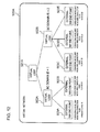
- a BCMC flow entry is generated for each forwarding node 200 and set in the forwarding node 200. Since fundamental configurations and operations are the same as in the first exemplary embodiment, a description is given below centered on differences with regard to BCMC flow entries.
- FIG. 13 to FIG. 15 are diagrams representing BCMC flow entries respectively set in the forwarding nodes 200A to 200C, in the second exemplary embodiment of the present invention. It is to be noted that in order to avoid duplication of the description, VLAN settings of ports of the forwarding nodes 200 are taken as being the same as in the first exemplary embodiment. As shown in in FIG. 18 to FIG. 20 , the BCMC flow entries differ from the first exemplary embodiment in the point that, in each forwarding node 200, correspondence relationships between port VLAN IDs and BC domains are 1-to-1 relationships.
- a flow entry flow entry No. 1 in Table #1 in FIG. 14
- a flow entry flow entry No. 2 in Table #1 in FIG. 14
- the number of BCMC flow entries related to an external NW connection port of a forwarding node 200 is the number of external NW connection ports in the forwarding node 200 (for example, the 2 entries, flow entry No. 1 and No. 2, in Table #1 of FIG. 7 ) + the number of VLAN IDs in all external NW endpoints 503 related to the forwarding node 200 (for example, the 2 entries, flow entry No. 1 and No. 2, in Table #2 of FIG. 7 ).
- the number of BCMC flow entries related to an external NW connection port of a forwarding node 200 is, at least, the total number of VLAN IDs in all external NW endpoints 503 related to the forwarding node 200 in question (for example, the 2 entries, flow entry No. 1 and No. 2, in Table #2 of FIG. 14 ).
- the more the same VLAN ID is set to plural external NW endpoints 503 related to the forwarding node 200 in question the more the number of BCMC flow entries increases, with respect to the first exemplary embodiment.
- the forwarding node control unit 102 of the control apparatus 100 generates BCMC flow entries, such that correspondence relationships between port VLAN IDs and BC domains are 1-to-1 relationships, in the forwarding node 200.
- Patent Literatures and Non-Patent Literatures are incorporated herein by reference thereto. Modifications and adjustments of exemplary embodiments and examples may be made within the bounds of the entire disclosure (including the scope of the claims) of the present invention, and also based on fundamental technological concepts thereof. Furthermore, various combinations and selections of various disclosed elements (including respective elements of the respective claims, respective elements of the respective exemplary embodiments and examples, respective elements of the respective drawings, and the like) are possible within the scope of the claims of the present invention. That is, the present invention clearly includes every type of transformation and modification that a person skilled in the art can realize according to the entire disclosure including the scope of the claims and to technological concepts thereof.
Landscapes
- Engineering & Computer Science (AREA)
- Multimedia (AREA)
- Computer Networks & Wireless Communication (AREA)
- Signal Processing (AREA)
- Computer Security & Cryptography (AREA)
- Data Exchanges In Wide-Area Networks (AREA)
Applications Claiming Priority (2)
| Application Number | Priority Date | Filing Date | Title |
|---|---|---|---|
| JP2012107595 | 2012-05-09 | ||
| PCT/JP2013/062929 WO2013168737A1 (fr) | 2012-05-09 | 2013-05-08 | Système de communication, dispositif de commande, procédé de communication, et programme |
Publications (2)
| Publication Number | Publication Date |
|---|---|
| EP2849397A1 true EP2849397A1 (fr) | 2015-03-18 |
| EP2849397A4 EP2849397A4 (fr) | 2015-12-23 |
Family
ID=49550771
Family Applications (1)
| Application Number | Title | Priority Date | Filing Date |
|---|---|---|---|
| EP13786966.5A Withdrawn EP2849397A4 (fr) | 2012-05-09 | 2013-05-08 | Système de communication, dispositif de commande, procédé de communication, et programme |
Country Status (5)
| Country | Link |
|---|---|
| US (1) | US9584568B2 (fr) |
| EP (1) | EP2849397A4 (fr) |
| JP (1) | JP5862769B2 (fr) |
| CN (1) | CN104272679B (fr) |
| WO (1) | WO2013168737A1 (fr) |
Cited By (5)
| Publication number | Priority date | Publication date | Assignee | Title |
|---|---|---|---|---|
| WO2018087721A1 (fr) * | 2016-11-11 | 2018-05-17 | Ologn Technologies Ag | Systèmes, appareils et procédés pour routeurs collaboratifs |
| US10419232B2 (en) | 2015-03-20 | 2019-09-17 | Nec Corporation | Control apparatus, communication system, control method and program |
| US10791052B2 (en) | 2016-07-05 | 2020-09-29 | Ologn Technologies Ag | Systems, apparatuses and methods for network packet management |
| US11570098B2 (en) | 2016-07-05 | 2023-01-31 | Six Impossible Things Before Breakfast Limited | Systems, apparatuses and methods for cooperating routers |
| US12238003B2 (en) | 2016-07-05 | 2025-02-25 | Six Impossible Things Before Breakfast Limited | Systems, apparatuses and methods for cooperating routers |
Families Citing this family (25)
| Publication number | Priority date | Publication date | Assignee | Title |
|---|---|---|---|---|
| US9648542B2 (en) | 2014-01-28 | 2017-05-09 | Brocade Communications Systems, Inc. | Session-based packet routing for facilitating analytics |
| CN103763146B (zh) * | 2014-01-29 | 2017-05-17 | 新华三技术有限公司 | 一种软件定义网络控制器及其生成转发信息的方法 |
| CN106416148A (zh) * | 2014-02-19 | 2017-02-15 | 日本电气株式会社 | 网络控制方法、网络系统、装置和程序 |
| US9807004B2 (en) * | 2014-04-01 | 2017-10-31 | Google Inc. | System and method for software defined routing of traffic within and between autonomous systems with enhanced flow routing, scalability and security |
| EP3139555A4 (fr) * | 2014-05-01 | 2017-12-27 | Nec Corporation | Dispositif de communication, dispositif de commande, système de communication, procédé pour traiter un paquet reçu, procédé pour commander un dispositif de communication et programme |
| WO2015196361A1 (fr) | 2014-06-24 | 2015-12-30 | 华为技术有限公司 | Procédé, appareil et système de multidiffusion pour un réseau défini par logiciel |
| CN109842529B (zh) | 2014-09-05 | 2021-10-26 | 华为技术有限公司 | 用于配置业务的方法、装置和网络系统 |
| JP6575527B2 (ja) * | 2014-11-11 | 2019-09-18 | 日本電気株式会社 | 通信管理装置、通信転送システム、通信管理方法、および通信管理プログラム |
| JP2018509842A (ja) * | 2015-03-19 | 2018-04-05 | ゼットティーイー コーポレイション | マルチドメイン仮想トポロジー(mdvt)を確立および管理するための方法およびシステム |
| US10129088B2 (en) | 2015-06-17 | 2018-11-13 | Extreme Networks, Inc. | Configuration of rules in a network visibility system |
| US9866478B2 (en) * | 2015-03-23 | 2018-01-09 | Extreme Networks, Inc. | Techniques for user-defined tagging of traffic in a network visibility system |
| US10771475B2 (en) | 2015-03-23 | 2020-09-08 | Extreme Networks, Inc. | Techniques for exchanging control and configuration information in a network visibility system |
| US10911353B2 (en) | 2015-06-17 | 2021-02-02 | Extreme Networks, Inc. | Architecture for a network visibility system |
| US10057126B2 (en) | 2015-06-17 | 2018-08-21 | Extreme Networks, Inc. | Configuration of a network visibility system |
| US10530688B2 (en) | 2015-06-17 | 2020-01-07 | Extreme Networks, Inc. | Configuration of load-sharing components of a network visibility router in a network visibility system |
| CN106411746A (zh) * | 2015-08-03 | 2017-02-15 | 上海宽带技术及应用工程研究中心 | 基于Vlan的SDN网络数据传输系统及方法 |
| US10243813B2 (en) | 2016-02-12 | 2019-03-26 | Extreme Networks, Inc. | Software-based packet broker |
| US10999200B2 (en) | 2016-03-24 | 2021-05-04 | Extreme Networks, Inc. | Offline, intelligent load balancing of SCTP traffic |
| CN107342940B (zh) * | 2016-04-29 | 2020-10-20 | 新华三技术有限公司 | 一种控制信息的生成方法及装置和报文处理方法及装置 |
| US10567259B2 (en) | 2016-10-19 | 2020-02-18 | Extreme Networks, Inc. | Smart filter generator |
| TWI636679B (zh) | 2017-02-07 | 2018-09-21 | 財團法人工業技術研究院 | 虛擬區域網路配置系統與方法及其電腦程式產品 |
| US12040965B2 (en) * | 2020-02-04 | 2024-07-16 | Nokia Solutions And Networks Oy | Supporting multicast communications |
| US11860802B2 (en) * | 2021-02-22 | 2024-01-02 | Nutanix, Inc. | Instant recovery as an enabler for uninhibited mobility between primary storage and secondary storage |
| JP7694439B2 (ja) * | 2022-03-31 | 2025-06-18 | 横河電機株式会社 | 情報処理装置、情報処理システム、情報処理方法、及びプログラム |
| JP7468566B2 (ja) * | 2022-03-31 | 2024-04-16 | 横河電機株式会社 | 情報処理装置、情報処理方法、及びプログラム |
Family Cites Families (20)
| Publication number | Priority date | Publication date | Assignee | Title |
|---|---|---|---|---|
| US6937574B1 (en) | 1999-03-16 | 2005-08-30 | Nortel Networks Limited | Virtual private networks and methods for their operation |
| JP3679336B2 (ja) | 2001-02-22 | 2005-08-03 | 日本電信電話株式会社 | パケットルーティング方法 |
| JP2004266874A (ja) | 2002-07-12 | 2004-09-24 | Nec Corp | ネットワークにおけるフレーム転送方法及びノード、フレーム転送プログラム |
| ES2228266B1 (es) | 2003-07-28 | 2006-06-01 | Diseño De Sistemas En Silicio, S.A. | Procedimiento de conmutacion de paquetes en un medio de transmision con multiples estaciones conectadas mediante distintos enlaces. |
| CN100461732C (zh) | 2006-06-16 | 2009-02-11 | 华为技术有限公司 | 一种以太技术交换和转发的方法、系统和设备 |
| JP5115033B2 (ja) * | 2007-05-30 | 2013-01-09 | 富士通株式会社 | パケット中継方法及び装置 |
| CN101079775A (zh) * | 2007-06-11 | 2007-11-28 | 华为技术有限公司 | 划分虚拟局域网,传送数据的方法和无线分组网关 |
| EP2179367B1 (fr) * | 2007-08-15 | 2017-10-04 | Cisco Technology, Inc. | Protocole de réservation de flux pour réseaux pontés |
| CN101217463B (zh) | 2007-12-27 | 2012-04-18 | 华为技术有限公司 | 一种控制报文转发的方法和设备 |
| US8125928B2 (en) | 2009-07-24 | 2012-02-28 | Juniper Networks, Inc. | Routing frames in a shortest path computer network for a multi-homed legacy bridge node |
| CN101778035B (zh) | 2010-03-09 | 2013-12-18 | 中兴通讯股份有限公司南京分公司 | 一种虚拟专用局域网通信的方法及装置 |
| CN102136981B (zh) * | 2010-06-29 | 2013-04-17 | 华为技术有限公司 | 以太网中实现以太树业务的方法和相关装置 |
| US8964528B2 (en) * | 2010-07-06 | 2015-02-24 | Nicira, Inc. | Method and apparatus for robust packet distribution among hierarchical managed switching elements |
| US9680750B2 (en) * | 2010-07-06 | 2017-06-13 | Nicira, Inc. | Use of tunnels to hide network addresses |
| WO2012090993A1 (fr) * | 2010-12-28 | 2012-07-05 | 日本電気株式会社 | Système d'information, dispositif de commande, procédé et programme de communication |
| US8964563B2 (en) * | 2011-07-08 | 2015-02-24 | Telefonaktiebolaget L M Ericsson (Publ) | Controller driven OAM for OpenFlow |
| US8971334B2 (en) * | 2011-08-02 | 2015-03-03 | Telefonaktiebolaget L M Ericsson (Publ) | Packet broadcast mechanism in a split architecture network |
| US8762501B2 (en) * | 2011-08-29 | 2014-06-24 | Telefonaktiebolaget L M Ericsson (Publ) | Implementing a 3G packet core in a cloud computer with openflow data and control planes |
| US8955093B2 (en) * | 2012-04-11 | 2015-02-10 | Varmour Networks, Inc. | Cooperative network security inspection |
| US10333827B2 (en) * | 2012-04-11 | 2019-06-25 | Varmour Networks, Inc. | Adaptive session forwarding following virtual machine migration detection |
-
2013
- 2013-05-08 JP JP2014514732A patent/JP5862769B2/ja not_active Expired - Fee Related
- 2013-05-08 CN CN201380023703.XA patent/CN104272679B/zh not_active Expired - Fee Related
- 2013-05-08 WO PCT/JP2013/062929 patent/WO2013168737A1/fr not_active Ceased
- 2013-05-08 US US14/398,950 patent/US9584568B2/en active Active
- 2013-05-08 EP EP13786966.5A patent/EP2849397A4/fr not_active Withdrawn
Cited By (17)
| Publication number | Priority date | Publication date | Assignee | Title |
|---|---|---|---|---|
| US10419232B2 (en) | 2015-03-20 | 2019-09-17 | Nec Corporation | Control apparatus, communication system, control method and program |
| EP4135232A1 (fr) * | 2016-07-05 | 2023-02-15 | Six Impossible Things Before Breakfast Limited | Systèmes, appareils et procédés de gestion de paquets de réseau |
| US11689462B2 (en) | 2016-07-05 | 2023-06-27 | Six Impossible Things Before Breakfast Limited | Systems, apparatuses and methods for network packet management |
| US10841222B2 (en) | 2016-07-05 | 2020-11-17 | Ologn Technologies Ag | Systems, apparatuses and methods for network packet management |
| US10841224B2 (en) | 2016-07-05 | 2020-11-17 | Ologn Technologies Ag | Systems, apparatuses and methods for network packet management |
| US10841223B2 (en) | 2016-07-05 | 2020-11-17 | Ologn Technologies Ag | Systems, apparatuses and methods for network packet management |
| US11563684B2 (en) | 2016-07-05 | 2023-01-24 | Six Impossible Things Before Breakfast | Systems, apparatuses and methods for network packet management |
| US10791052B2 (en) | 2016-07-05 | 2020-09-29 | Ologn Technologies Ag | Systems, apparatuses and methods for network packet management |
| US11570098B2 (en) | 2016-07-05 | 2023-01-31 | Six Impossible Things Before Breakfast Limited | Systems, apparatuses and methods for cooperating routers |
| US11601366B2 (en) | 2016-07-05 | 2023-03-07 | Six Impossible Things Before Breakfast Limited | Systems, apparatuses and methods for network packet management |
| US12238003B2 (en) | 2016-07-05 | 2025-02-25 | Six Impossible Things Before Breakfast Limited | Systems, apparatuses and methods for cooperating routers |
| US11689461B2 (en) | 2016-07-05 | 2023-06-27 | Six Impossible Things Before Breakfast Limited | Systems, apparatuses and methods for network packet management |
| US11689460B2 (en) | 2016-07-05 | 2023-06-27 | Six Impossible Things Before Breakfast Limited | Systems, apparatuses and methods for network packet management |
| US11855895B2 (en) | 2016-07-05 | 2023-12-26 | Six Impossible Things Before Breakfast Limited | Systems, apparatuses and methods for network packet management |
| US12149447B2 (en) | 2016-07-05 | 2024-11-19 | Six Impossible Things Before Breakfast Limited | Systems, apparatuses and methods for network packet management |
| US12212492B2 (en) | 2016-07-05 | 2025-01-28 | Six Impossible Things Before Breakfast Limited | Systems, apparatuses and methods for network packet management |
| WO2018087721A1 (fr) * | 2016-11-11 | 2018-05-17 | Ologn Technologies Ag | Systèmes, appareils et procédés pour routeurs collaboratifs |
Also Published As
| Publication number | Publication date |
|---|---|
| JPWO2013168737A1 (ja) | 2016-01-07 |
| WO2013168737A1 (fr) | 2013-11-14 |
| US20150103824A1 (en) | 2015-04-16 |
| CN104272679B (zh) | 2018-02-13 |
| CN104272679A (zh) | 2015-01-07 |
| JP5862769B2 (ja) | 2016-02-16 |
| US9584568B2 (en) | 2017-02-28 |
| EP2849397A4 (fr) | 2015-12-23 |
Similar Documents
| Publication | Publication Date | Title |
|---|---|---|
| US9584568B2 (en) | Signal processing apparatus and signal processing method thereof for implementing a broadcast or a multicast communication | |
| US9083612B2 (en) | Communication system, control apparatus, communication method, and program | |
| US9843504B2 (en) | Extending OpenFlow to support packet encapsulation for transport over software-defined networks | |
| US10237377B2 (en) | Packet rewriting apparatus, control apparatus, communication system, packet transmission method and program | |
| US9258220B2 (en) | Communication system, node, control server, communication method and program | |
| US10069648B2 (en) | Communication system, control apparatus, communication control method and program | |
| US10645006B2 (en) | Information system, control apparatus, communication method, and program | |
| US20130144995A1 (en) | Control apparatus, a communication system, a communication method and a recording medium having recorded thereon a communication program | |
| JP2017506025A (ja) | ネットワークサービス挿入を実行するシステム及び方法 | |
| CN104509045A (zh) | 控制装置、通信系统、通信方法和程序 | |
| WO2012081721A1 (fr) | Système de communication, noeud, procédé de transfert de paquets et programme | |
| US20190007279A1 (en) | Control apparatus, communication system, virtual network management method, and program | |
| US10270605B2 (en) | Control apparatus, communication system, communication node control method, and program | |
| JP6206493B2 (ja) | 制御装置、通信システム、中継装置の制御方法及びプログラム | |
| CN101171802A (zh) | 节点,网络,对应关系产生方法和帧传送程序 | |
| WO2014199924A1 (fr) | Dispositif de commande, système de communication, et procédé et programme de commande d'un dispositif relais | |
| EP3104562B1 (fr) | Méthode d'agrégation des flux dans des réseaux de tic | |
| CN114079640B (zh) | 一种数据处理方法、用户面功能及装置 | |
| JP6292292B2 (ja) | 通信ノード、制御装置、通信システム、通信方法及びプログラム | |
| JP5854488B2 (ja) | 通信システム、制御装置、処理規則の設定方法およびプログラム | |
| CN114666269A (zh) | 一种基于ip子网的vlan的报文转发方法、装置、设备及介质 | |
| WO2024007762A1 (fr) | Procédé de publication de voie d'acheminement, et procédé et appareil de communication |
Legal Events
| Date | Code | Title | Description |
|---|---|---|---|
| PUAI | Public reference made under article 153(3) epc to a published international application that has entered the european phase |
Free format text: ORIGINAL CODE: 0009012 |
|
| 17P | Request for examination filed |
Effective date: 20141209 |
|
| AK | Designated contracting states |
Kind code of ref document: A1 Designated state(s): AL AT BE BG CH CY CZ DE DK EE ES FI FR GB GR HR HU IE IS IT LI LT LU LV MC MK MT NL NO PL PT RO RS SE SI SK SM TR |
|
| AX | Request for extension of the european patent |
Extension state: BA ME |
|
| DAX | Request for extension of the european patent (deleted) | ||
| RA4 | Supplementary search report drawn up and despatched (corrected) |
Effective date: 20151124 |
|
| RIC1 | Information provided on ipc code assigned before grant |
Ipc: H04L 12/717 20130101ALI20151118BHEP Ipc: H04L 12/46 20060101ALI20151118BHEP Ipc: H04L 29/06 20060101AFI20151118BHEP Ipc: H04L 12/761 20130101ALI20151118BHEP |
|
| 17Q | First examination report despatched |
Effective date: 20181019 |
|
| STAA | Information on the status of an ep patent application or granted ep patent |
Free format text: STATUS: THE APPLICATION IS DEEMED TO BE WITHDRAWN |
|
| 18D | Application deemed to be withdrawn |
Effective date: 20201126 |