EP2849552A2 - Appareil pour abriter une ou plusieurs alimentations - Google Patents
Appareil pour abriter une ou plusieurs alimentations Download PDFInfo
- Publication number
- EP2849552A2 EP2849552A2 EP14183389.7A EP14183389A EP2849552A2 EP 2849552 A2 EP2849552 A2 EP 2849552A2 EP 14183389 A EP14183389 A EP 14183389A EP 2849552 A2 EP2849552 A2 EP 2849552A2
- Authority
- EP
- European Patent Office
- Prior art keywords
- air flow
- storage area
- power supplies
- air
- compartment
- Prior art date
- Legal status (The legal status is an assumption and is not a legal conclusion. Google has not performed a legal analysis and makes no representation as to the accuracy of the status listed.)
- Withdrawn
Links
Images
Classifications
-
- H—ELECTRICITY
- H05—ELECTRIC TECHNIQUES NOT OTHERWISE PROVIDED FOR
- H05K—PRINTED CIRCUITS; CASINGS OR CONSTRUCTIONAL DETAILS OF ELECTRIC APPARATUS; MANUFACTURE OF ASSEMBLAGES OF ELECTRICAL COMPONENTS
- H05K7/00—Constructional details common to different types of electric apparatus
- H05K7/20—Modifications to facilitate cooling, ventilating, or heating
- H05K7/20009—Modifications to facilitate cooling, ventilating, or heating using a gaseous coolant in electronic enclosures
- H05K7/20136—Forced ventilation, e.g. by fans
- H05K7/20145—Means for directing air flow, e.g. ducts, deflectors, plenum or guides
-
- H—ELECTRICITY
- H05—ELECTRIC TECHNIQUES NOT OTHERWISE PROVIDED FOR
- H05K—PRINTED CIRCUITS; CASINGS OR CONSTRUCTIONAL DETAILS OF ELECTRIC APPARATUS; MANUFACTURE OF ASSEMBLAGES OF ELECTRICAL COMPONENTS
- H05K7/00—Constructional details common to different types of electric apparatus
- H05K7/20—Modifications to facilitate cooling, ventilating, or heating
- H05K7/2089—Modifications to facilitate cooling, ventilating, or heating for power electronics, e.g. for inverters for controlling motor
- H05K7/20909—Forced ventilation, e.g. on heat dissipaters coupled to components
-
- H—ELECTRICITY
- H05—ELECTRIC TECHNIQUES NOT OTHERWISE PROVIDED FOR
- H05K—PRINTED CIRCUITS; CASINGS OR CONSTRUCTIONAL DETAILS OF ELECTRIC APPARATUS; MANUFACTURE OF ASSEMBLAGES OF ELECTRICAL COMPONENTS
- H05K7/00—Constructional details common to different types of electric apparatus
- H05K7/20—Modifications to facilitate cooling, ventilating, or heating
- H05K7/20009—Modifications to facilitate cooling, ventilating, or heating using a gaseous coolant in electronic enclosures
- H05K7/20136—Forced ventilation, e.g. by fans
- H05K7/20172—Fan mounting or fan specifications
-
- H—ELECTRICITY
- H05—ELECTRIC TECHNIQUES NOT OTHERWISE PROVIDED FOR
- H05K—PRINTED CIRCUITS; CASINGS OR CONSTRUCTIONAL DETAILS OF ELECTRIC APPARATUS; MANUFACTURE OF ASSEMBLAGES OF ELECTRICAL COMPONENTS
- H05K7/00—Constructional details common to different types of electric apparatus
- H05K7/20—Modifications to facilitate cooling, ventilating, or heating
- H05K7/20536—Modifications to facilitate cooling, ventilating, or heating for racks or cabinets of standardised dimensions, e.g. electronic racks for aircraft or telecommunication equipment
- H05K7/20554—Forced ventilation of a gaseous coolant
- H05K7/20572—Forced ventilation of a gaseous coolant within cabinets for removing heat from sub-racks, e.g. plenum
-
- H—ELECTRICITY
- H05—ELECTRIC TECHNIQUES NOT OTHERWISE PROVIDED FOR
- H05K—PRINTED CIRCUITS; CASINGS OR CONSTRUCTIONAL DETAILS OF ELECTRIC APPARATUS; MANUFACTURE OF ASSEMBLAGES OF ELECTRICAL COMPONENTS
- H05K7/00—Constructional details common to different types of electric apparatus
- H05K7/20—Modifications to facilitate cooling, ventilating, or heating
- H05K7/20709—Modifications to facilitate cooling, ventilating, or heating for server racks or cabinets; for data centers, e.g. 19-inch computer racks
- H05K7/20718—Forced ventilation of a gaseous coolant
Definitions
- the present invention relates to an apparatus for housing one or more power supplies and more specifically power supplies for an ink curing system.
- PSC power supply cabinets
- moving PSCs can be awkward in confined spaces due to lack of lifting device access.
- US patent publication no. 2009/0080156 discloses a cooling arrangement to cool components on a circuit board having multiple fans at different angles and distances to/from the front face.
- the arrangement disclosed in US 2009/0080156 has significant disadvantages in terms of the cooling effect that can be achieved and the ease of access to the circuit board contained therein.
- the present invention sets out to provide an improved apparatus for housing power supplies, which alleviates the problems described above.
- the present invention is particularly suited to use with ink curing apparatus where effective cooling provides significant advantages in terms of the efficiency of the apparatus, particularly where available space is restricted.
- the invention provides an apparatus for housing one or more power supplies, the apparatus comprising:-
- This unique airflow path not only allows the power supplies to be efficiently cooled, but also means that the power supplies can be provided at an orientation within the apparatus that allows the front of the power supplies to be easily accessed by a user.
- Each fan is positioned equidistant from the front of the apparatus such that each fan draws air into the apparatus at the same temperature to achieve uniform cooling through the storage area.
- the point at which cool air enters the apparatus is far away from the point at which warm air exits; i.e. the distance between the air inlet and air outlet is maximised.
- the first air flow compartment comprises one or more vents facing towards the front of the apparatus.
- each fan is positioned adjacent to a vent.
- the first air flow compartment comprises three fans and three vents.
- one side of the first air flow compartment comprises one or more vents and forms an air inlet side of the storage area.
- one side of the second airflow compartment comprises one or more vents and forms an air outlet side of the storage area.
- the rear of the second air flow compartment comprises one or more vents for exit of air out of the rear of the apparatus.
- the rear of the apparatus comprises one or more protrusions for providing a gap at the rear of the apparatus when placed against a wall.
- the storage area is accessible from the front of the apparatus.
- the apparatus comprises a door.
- the door comprises an air filter.
- the storage area comprises one or more racks for holding one or more power supplies.
- the apparatus is a cabinet.
- the apparatus comprises a distribution unit.
- the distribution unit comprises a cover.
- the cover for the distribution unit comprises one or more apertures.
- the apparatus comprises one or more apertures for entry of one or more cables into the apparatus.
- the one or more apertures are provided in the base and/or top surface of the apparatus.
- one or more of the one or more apertures leads to a passageway for accommodating one or more cables.
- the passageway is provided in the base of the apparatus.
- the passageway comprises one or more apertures for entry and exit of cables through one or more apertures of a second apparatus of the present invention when a first apparatus of the present invention is stacked upon or placed next to a second apparatus of the present invention.
- the passageway comprises an opening along at least a part of its base.
- the apparatus comprises channels for accommodating the forks of a forklift truck.
- the channels are provided in the base of the apparatus.
- the channels are open to the front and rear of the apparatus. This allows lifting slings to be inserted through the channels and the apparatus to be lifted by a hoist.
- the apparatus comprises a removable cover for the channels.
- the apparatus comprises a pair of channels.
- a space is provided between the channels for accommodating the forks of a pallet truck.
- the present invention relates to an apparatus, for example a cabinet, for housing one or more power supplies.
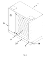
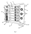
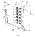
- an apparatus 1 in the form of a cabinet, is shown for housing one or more power supplies 2.
- the cabinet 1 comprises a door 3 which, when opened, allows access to a storage area 4.
- the power supplies 2 are mounted on rails 25 and can be slid in and out of the storage area 4 as and when the need arises.
- the power supplies 2 are stacked orthogonally to the air inlet path, which is described below.
- the cabinet 1 includes first 5 and second 6 air flow compartments provided at either opposing sides of the storage area 4.
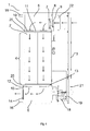
- the first airflow compartment 5 comprises at least two fans 7 mounted in or adjacent to its front surface 8. In the embodiment shown in Figure 2 , there are three fans, which are each aligned with and adjacent to an inlet vent 9. Each fan 7 is positioned to be equidistant from the front of the apparatus 1. As shown by the direction of the arrows in Figure 4 , the fans 7 draw air from in front of the cabinet 1, each fan draws air primarily through the vent 9 to which it is adjacent. Thus, air is drawn through the vents 9 in the front surface 8 of the first airflow compartment 5 with the air entering the cabinet 1 through each vent 9 being at substantially the same temperature as air being drawn in from the adjacent vents. The air drawn in through the vents creates an increased pressure within the first airflow compartment causing air to be directed through side vents 10 in the wall 11 between the first airflow compartment 5 and the storage area 4.
- the second airflow compartment 6 is provided with vents 12 in the wall 13 between the storage area 4 and the second airflow compartment 6. Vents 14 are also provided in the rear wall 15 of the second airflow compartment 6.
- the air which is directed through the vents 10 in the wall 11 between the first airflow compartment 5 and the storage area 4 passes across the storage area 4 and thus through and/or around power supplies 2 housed within the storage area 4, through the vents 12 in the wall 13 between the storage area 4 and the second airflow compartment 6, and then out of the rear of the cabinet 1 through the vents 14 in the rear wall 15 of the second airflow compartment 6.
- This unique airflow path not only allows the power supplies 2 to be efficiently cooled, but also means that the power supplies 2 can be provided at an orientation within the cabinet 1 which allows the front of the power supplies 2 to be easily accessed by a user.
- the point at which cool air enters the cabinet 1 is far away from the point at which warm air exits the cabinet 1.
- the air flow path is configured to maximise the distance between the cool air inlet and the warm air outlet. This makes the cooling ability of the cabinet 1 much greater and more efficient. This is not only of benefit in terms of the ability of the cabinet 1 to keep the power supplies 2 cool, but also means that running costs and the environmental impact (of the apparatus contained therein) are reduced.
- a plurality of cabinets can be placed side by side without a gap provided between them and without affecting the cooling efficiency of the cabinets.
- a plurality of cabinets can similarly be stacked.
- the cabinet 1 is provided with two protrusions 16 extending from the rear of the cabinet 1. These protrusions 16 ensure that a gap is provided at the rear of the cabinet 1 when the cabinet 1 is placed against a wall.
- the door 3 is provided with a grill 17 to allow air to enter the cabinet 1 even when the door 3 is closed.
- the door 3 is also provided with an air filter (not shown) to ensure that air entering the cabinet 1 is clean.
- the cabinet 1 comprises a distribution unit 18.
- the distribution unit 18 is provided with a cover 19.
- the cover 19 comprises apertures 20 to allow access to the distribution unit 18.
- the distribution unit 18 includes circuit breakers and power distribution for the power supplies 2.
- a second door 21 on the front of the cabinet 1 encloses the distribution unit 18 and cover 19 within the cabinet 1.
- the distribution unit 18 is positioned in front of the second airflow compartment 6.
- the cabinet 1 includes apertures 22, 23 in its base and top panel through which one or more cables can pass.
- the apertures may be provided with removable covers.
- the apertures 22 in the base lead to a passageway 24 provided within the base of the cabinet 1 for accommodating a run of cables (not shown).
- the passageway 24 is open at its base so that it can be accessed through an aperture 23 in the top surface of a lower cabinet 1 when two cabinets are stacked together. This arrangement of apertures and passageway allows cables to be fed into the cabinet 1 when the cabinet 1 is one of a plurality stacked together or positioned side by side.
- channels 26 are provided in the base of the cabinet 1 into which lifting forks of a forklift truck can be inserted.
- the channels 26 are hidden behind a panel/cover 25 which can easily be removed to expose the channels 26.
- the channels 26 are enclosed at their top, bottom and sides and so the cabinet can be lifted without fear of tipping. Lifting slings can be threaded through the channels 26 to allow lifting with a lifting hoist.
- a space 27 between the channels 26 allows pallet truck access.
Landscapes
- Engineering & Computer Science (AREA)
- Microelectronics & Electronic Packaging (AREA)
- Physics & Mathematics (AREA)
- Thermal Sciences (AREA)
- Aviation & Aerospace Engineering (AREA)
- Computer Hardware Design (AREA)
- General Engineering & Computer Science (AREA)
- Cooling Or The Like Of Electrical Apparatus (AREA)
- Secondary Cells (AREA)
Applications Claiming Priority (2)
| Application Number | Priority Date | Filing Date | Title |
|---|---|---|---|
| GBGB1316146.8A GB201316146D0 (en) | 2013-09-11 | 2013-09-11 | Apparatus for housing one or more power supplies |
| GB1415422.3A GB2519424A (en) | 2013-09-11 | 2014-09-01 | Apparatus for housing one or more power supplies |
Publications (2)
| Publication Number | Publication Date |
|---|---|
| EP2849552A2 true EP2849552A2 (fr) | 2015-03-18 |
| EP2849552A3 EP2849552A3 (fr) | 2015-04-15 |
Family
ID=49487037
Family Applications (1)
| Application Number | Title | Priority Date | Filing Date |
|---|---|---|---|
| EP14183389.7A Withdrawn EP2849552A3 (fr) | 2013-09-11 | 2014-09-03 | Appareil pour abriter une ou plusieurs alimentations |
Country Status (3)
| Country | Link |
|---|---|
| US (1) | US20150072607A1 (fr) |
| EP (1) | EP2849552A3 (fr) |
| GB (2) | GB201316146D0 (fr) |
Cited By (1)
| Publication number | Priority date | Publication date | Assignee | Title |
|---|---|---|---|---|
| EP4383966A1 (fr) * | 2022-12-06 | 2024-06-12 | SK On Co., Ltd. | Système de conversion de puissance |
Families Citing this family (1)
| Publication number | Priority date | Publication date | Assignee | Title |
|---|---|---|---|---|
| US11246241B1 (en) * | 2020-03-04 | 2022-02-08 | Amazon Technologies, Inc. | Movable media air handling unit |
Family Cites Families (16)
| Publication number | Priority date | Publication date | Assignee | Title |
|---|---|---|---|---|
| US5370576A (en) * | 1993-01-13 | 1994-12-06 | Eleanor L. Sackett | Sidewall vent-mounted fan assembly for a truck cab |
| CA2165749C (fr) * | 1995-12-20 | 2003-04-08 | Paul D. Cochrane | Materiel electronique comportant des passages de circulation d'air de refroidissement |
| TW321414U (en) * | 1997-05-07 | 1997-11-21 | Amtran Technology Co Ltd | Pivot-rotation device of flat-display panel |
| US6850685B2 (en) * | 2002-03-27 | 2005-02-01 | Adc Telecommunications, Inc. | Termination panel with pivoting bulkhead and cable management |
| US7316606B2 (en) * | 2005-02-08 | 2008-01-08 | Intel Corporation | Auxiliary airflow system |
| US20070211439A1 (en) * | 2006-03-08 | 2007-09-13 | Hit Co., Ltd. | Electronic apparatus having drawer trays |
| US20080113604A1 (en) * | 2006-10-10 | 2008-05-15 | Motorola, Inc. | Embedded computer chassis with service fan tray |
| US7492591B1 (en) * | 2007-01-10 | 2009-02-17 | Juniper Networks, Inc. | Reversible airflow fan tray for an electronic device |
| WO2009042735A1 (fr) * | 2007-09-25 | 2009-04-02 | Blade Network Technologies, Inc. | Appareil permettant de changer extérieurement la direction de l'air circulant à travers un équipement électronique |
| CN101516166B (zh) * | 2008-02-22 | 2010-12-08 | 华为技术有限公司 | 一种横插框及通信机柜 |
| DE102010052751A1 (de) * | 2010-11-30 | 2012-05-31 | Christmann Informationstechnik + Medien Gmbh & Co. Kg | Computersystem und Prozessor-Einschubbaugruppe dafür |
| FR2969379B1 (fr) * | 2010-12-17 | 2013-02-15 | Thales Sa | Refroidissement d'un equipement electronique |
| US20120293951A1 (en) * | 2011-05-16 | 2012-11-22 | Delta Electronics, Inc. | Rack mounted computer system and cooling structure thereof |
| US8848367B2 (en) * | 2011-09-15 | 2014-09-30 | Panduit Corp. | Thermal management system |
| US9167726B2 (en) * | 2011-11-17 | 2015-10-20 | Cray Inc. | Transverse cooling system and method |
| JP5953734B2 (ja) * | 2011-12-20 | 2016-07-20 | 富士通株式会社 | 放熱器、積層型電子デバイス、及び電子機器。 |
-
2013
- 2013-09-11 GB GBGB1316146.8A patent/GB201316146D0/en not_active Ceased
-
2014
- 2014-09-01 GB GB1415422.3A patent/GB2519424A/en not_active Withdrawn
- 2014-09-03 EP EP14183389.7A patent/EP2849552A3/fr not_active Withdrawn
- 2014-09-10 US US14/482,743 patent/US20150072607A1/en not_active Abandoned
Non-Patent Citations (1)
| Title |
|---|
| None * |
Cited By (1)
| Publication number | Priority date | Publication date | Assignee | Title |
|---|---|---|---|---|
| EP4383966A1 (fr) * | 2022-12-06 | 2024-06-12 | SK On Co., Ltd. | Système de conversion de puissance |
Also Published As
| Publication number | Publication date |
|---|---|
| GB2519424A (en) | 2015-04-22 |
| EP2849552A3 (fr) | 2015-04-15 |
| US20150072607A1 (en) | 2015-03-12 |
| GB201415422D0 (en) | 2014-10-15 |
| GB201316146D0 (en) | 2013-10-23 |
Similar Documents
| Publication | Publication Date | Title |
|---|---|---|
| US8310832B2 (en) | Side-exhaust cooling system for rack mounted equipment | |
| US10588245B2 (en) | Assembly for extracting heat from a housing for electronic equipment | |
| US7604535B2 (en) | Assembly for extracting heat from a housing for electronic equipment | |
| US20080151496A1 (en) | Cabinet for electronic devices | |
| CN101502194B (zh) | 电子器件底架的气流管理系统 | |
| US6516954B2 (en) | Equipment rack with integral HVAC and power distribution features | |
| US8520385B2 (en) | Server rack | |
| US20090061755A1 (en) | Intake Duct | |
| US20130300266A1 (en) | Modular Containment System | |
| US20140206271A1 (en) | Electronics rack cooling duct | |
| US20100091458A1 (en) | Electronics chassis with angled card cage | |
| US10026454B2 (en) | Storage system with cross flow cooling of power supply unit | |
| IN2012DN06568A (fr) | ||
| US8908368B2 (en) | Rack level hot aisle containment system | |
| US10492336B2 (en) | Subrack assembly for electronic equipment | |
| EP2849552A2 (fr) | Appareil pour abriter une ou plusieurs alimentations | |
| US20190274235A1 (en) | Housing having configurable airflow exhaust | |
| EP3251475B1 (fr) | Bâti mobile | |
| JP6379371B2 (ja) | 機器ユニット収納用キャビネット | |
| US20140182812A1 (en) | Cooling system | |
| KR20220137441A (ko) | 배전반의 공기흡입장치 | |
| KR950026071A (ko) | 인출형 전기기기용 크레이들 및 이를 구비한 폐쇄배전반 | |
| US20100321886A1 (en) | Enclosure Element | |
| KR101693463B1 (ko) | 차폐구조를 가지는 가변형 랙킹시스템 | |
| JP2009266914A (ja) | 電気電子機器収納用キャビネットの冷却構造 |
Legal Events
| Date | Code | Title | Description |
|---|---|---|---|
| PUAL | Search report despatched |
Free format text: ORIGINAL CODE: 0009013 |
|
| PUAI | Public reference made under article 153(3) epc to a published international application that has entered the european phase |
Free format text: ORIGINAL CODE: 0009012 |
|
| 17P | Request for examination filed |
Effective date: 20140903 |
|
| AK | Designated contracting states |
Kind code of ref document: A2 Designated state(s): AL AT BE BG CH CY CZ DE DK EE ES FI FR GB GR HR HU IE IS IT LI LT LU LV MC MK MT NL NO PL PT RO RS SE SI SK SM TR |
|
| AX | Request for extension of the european patent |
Extension state: BA ME |
|
| AK | Designated contracting states |
Kind code of ref document: A3 Designated state(s): AL AT BE BG CH CY CZ DE DK EE ES FI FR GB GR HR HU IE IS IT LI LT LU LV MC MK MT NL NO PL PT RO RS SE SI SK SM TR |
|
| AX | Request for extension of the european patent |
Extension state: BA ME |
|
| RIC1 | Information provided on ipc code assigned before grant |
Ipc: H05K 7/20 20060101AFI20150306BHEP |
|
| R17P | Request for examination filed (corrected) |
Effective date: 20151015 |
|
| RBV | Designated contracting states (corrected) |
Designated state(s): AL AT BE BG CH CY CZ DE DK EE ES FI FR GB GR HR HU IE IS IT LI LT LU LV MC MK MT NL NO PL PT RO RS SE SI SK SM TR |
|
| 17Q | First examination report despatched |
Effective date: 20170221 |
|
| STAA | Information on the status of an ep patent application or granted ep patent |
Free format text: STATUS: THE APPLICATION IS DEEMED TO BE WITHDRAWN |
|
| 18D | Application deemed to be withdrawn |
Effective date: 20170704 |