EP2849608B1 - Module de meuble - Google Patents
Module de meuble Download PDFInfo
- Publication number
- EP2849608B1 EP2849608B1 EP13722292.3A EP13722292A EP2849608B1 EP 2849608 B1 EP2849608 B1 EP 2849608B1 EP 13722292 A EP13722292 A EP 13722292A EP 2849608 B1 EP2849608 B1 EP 2849608B1
- Authority
- EP
- European Patent Office
- Prior art keywords
- furniture module
- height
- furniture
- extension body
- pedestal
- Prior art date
- Legal status (The legal status is an assumption and is not a legal conclusion. Google has not performed a legal analysis and makes no representation as to the accuracy of the status listed.)
- Not-in-force
Links
- NJPPVKZQTLUDBO-UHFFFAOYSA-N novaluron Chemical compound C1=C(Cl)C(OC(F)(F)C(OC(F)(F)F)F)=CC=C1NC(=O)NC(=O)C1=C(F)C=CC=C1F NJPPVKZQTLUDBO-UHFFFAOYSA-N 0.000 claims 11
- 238000009434 installation Methods 0.000 description 6
- 238000011161 development Methods 0.000 description 2
- 230000018109 developmental process Effects 0.000 description 2
- 230000002093 peripheral effect Effects 0.000 description 2
- 238000010008 shearing Methods 0.000 description 2
- 238000005253 cladding Methods 0.000 description 1
- 150000001875 compounds Chemical class 0.000 description 1
- 238000010276 construction Methods 0.000 description 1
- 230000003203 everyday effect Effects 0.000 description 1
- 230000001771 impaired effect Effects 0.000 description 1
- 230000000276 sedentary effect Effects 0.000 description 1
- 239000007787 solid Substances 0.000 description 1
Images





Classifications
-
- A—HUMAN NECESSITIES
- A47—FURNITURE; DOMESTIC ARTICLES OR APPLIANCES; COFFEE MILLS; SPICE MILLS; SUCTION CLEANERS IN GENERAL
- A47B—TABLES; DESKS; OFFICE FURNITURE; CABINETS; DRAWERS; GENERAL DETAILS OF FURNITURE
- A47B51/00—Cabinets with means for moving compartments up and down
-
- A—HUMAN NECESSITIES
- A47—FURNITURE; DOMESTIC ARTICLES OR APPLIANCES; COFFEE MILLS; SPICE MILLS; SUCTION CLEANERS IN GENERAL
- A47B—TABLES; DESKS; OFFICE FURNITURE; CABINETS; DRAWERS; GENERAL DETAILS OF FURNITURE
- A47B77/00—Kitchen cabinets
- A47B77/02—General layout, e.g. relative arrangement of compartments, working surface or surfaces, supports for apparatus
- A47B77/022—Work tops
-
- A—HUMAN NECESSITIES
- A47—FURNITURE; DOMESTIC ARTICLES OR APPLIANCES; COFFEE MILLS; SPICE MILLS; SUCTION CLEANERS IN GENERAL
- A47B—TABLES; DESKS; OFFICE FURNITURE; CABINETS; DRAWERS; GENERAL DETAILS OF FURNITURE
- A47B77/00—Kitchen cabinets
- A47B77/04—Provision for particular uses of compartments or other parts ; Compartments moving up and down, revolving parts
- A47B77/06—Provision for particular uses of compartments or other parts ; Compartments moving up and down, revolving parts for incorporating sinks, with or without draining boards, splash-backs, or the like
-
- A—HUMAN NECESSITIES
- A47—FURNITURE; DOMESTIC ARTICLES OR APPLIANCES; COFFEE MILLS; SPICE MILLS; SUCTION CLEANERS IN GENERAL
- A47B—TABLES; DESKS; OFFICE FURNITURE; CABINETS; DRAWERS; GENERAL DETAILS OF FURNITURE
- A47B2200/00—General construction of tables or desks
- A47B2200/0035—Tables or desks with features relating to adjustability or folding
- A47B2200/004—Top adjustment
- A47B2200/0042—Height and inclination adjustable desktop, either separately or simultaneously
-
- A—HUMAN NECESSITIES
- A47—FURNITURE; DOMESTIC ARTICLES OR APPLIANCES; COFFEE MILLS; SPICE MILLS; SUCTION CLEANERS IN GENERAL
- A47B—TABLES; DESKS; OFFICE FURNITURE; CABINETS; DRAWERS; GENERAL DETAILS OF FURNITURE
- A47B2200/00—General construction of tables or desks
- A47B2200/0035—Tables or desks with features relating to adjustability or folding
- A47B2200/004—Top adjustment
- A47B2200/0043—Inclination adjustable work top
-
- A—HUMAN NECESSITIES
- A47—FURNITURE; DOMESTIC ARTICLES OR APPLIANCES; COFFEE MILLS; SPICE MILLS; SUCTION CLEANERS IN GENERAL
- A47B—TABLES; DESKS; OFFICE FURNITURE; CABINETS; DRAWERS; GENERAL DETAILS OF FURNITURE
- A47B2220/00—General furniture construction, e.g. fittings
- A47B2220/0002—Adjustable furniture construction
- A47B2220/0013—Table or cupboards with upwardly concealable compartments
Definitions
- the invention relates to a furniture module according to the preamble of claim 1 and a device according to the preamble of claim 9.
- a device for height adjustment of a worktop of a kitchen furniture which has an actuator for the slidably mounted in a vertical guide worktop, wherein the guide arranged at a mutual distance, parallel guide columns, each of a supported on a supporting wall of a furniture body hollow section and a slidably mounted in this hollow profile support profile for the worktop, wherein the hollow sections of the paired guide columns are provided between them, extending in the direction of the depth of the worktop, common support walls of the furniture body are supported and wherein the worktop for each pair of columns with the hollow profiles Support walls enclosing cladding.
- a kitchen work unit which comprises a kitchen cabinet with side walls, rear wall and doors, in which a lower guide column and an upper guide column is arranged, wherein the upper guide column is guided vertically adjustable on the lower guide column and carries on support profiles a worktop.
- a kitchen work unit known in which a worktop rests as a boom on an approximately V-shaped support arm, wherein the support arm is connected to a vertical column, which is guided in height adjustable in a lower guide column.
- the US 5,461,974 A describes a workstation with an integrated computer, the workstation is height adjustable and a worktop is tilted.
- the US 5,339,750 A teaches a height-adjustable work table.
- the invention has for its object to design a height-adjustable furniture module with boom so that it can be optimally integrated into a modular device and that this particular in any orientation about a vertical axis in a modular device can be integrated and that this meets high safety requirements.
- the furniture module according to the invention for a kitchen and / or a bathroom comprises a base body, a telescopic box, a boom body and a lifting device, wherein the base body is formed as a cuboid component of the furniture module having an interior, wherein the boom body is formed as a cuboid component of the furniture module housing, wherein the lifting device between the base body and the armature body is arranged, wherein the lifting device at least partially passes through the telescopic box, wherein the lifting device moves the boom body upwards and downwards relative to the base body, wherein between the first lifting device and the Boom body is arranged a fitting device, wherein the boom body with the help of the fitting device relative to the lifting device in a horizontal plane displaceable is and / or wherein the boom body with the aid of the fitting device relative to the lifting device by at least one, preferably two and in particular three orthogonal spatial axes is pivotable.
- the invention provides to connect the telescopic box with the boom body and to move by the lifting device together with the boom body, wherein the telescopic box is guided vertically movable from the base body and in particular in the base body.
- a compound of the three mutually occluding or guided into each other solid body is formed between a boom body and the telescopic box comprehensive lifting unit and a base unit comprehensive the base body an all-round enclosed space in which the lifting device is added.
- a covering of the lifting device is guaranteed in all positions of the furniture module, so that in everyday use, regardless of the installation orientation dangerous access to the lifting device is effectively prevented.
- the invention also provides to blind the boom body forward, to the sides and to the rear or to blind the boom body at its rear. As a result, an access protection to an interior of the furniture module is also given if the furniture module is installed in such a way that this does not face a wall with its rear side.
- the invention also provides to conceal the telescopic box and / or the base box forward, to the sides and in particular to the rear.
- a free-standing installation of the furniture module is also possible without undesired access to its interior space being possible.
- the invention provides a connection of the base body, in which the base body with the lifting device installed therein is connected either as a freestanding base exclusively to a floor of a room in which the furniture module is arranged, or as a wall-hung base exclusively with a wall a room, in which the furniture module is arranged, is connected or connected to a floor and a wall of a room in which the furniture module is arranged, or floor connected to a wall of a room in which the furniture module is arranged, or floorstanding connected to a cheek of a neighboring furniture module.
- the invention also provides to form the boom body of the furniture module with appropriate width and depth.
- a mobility of the boom body in which it is movable such that its upper side in a lower position as a work surface, in particular in a height of 50 cm to 120 cm and preferably from 73 cm to 107 cm can be used.
- the work surface is suitable both for a seated, ergonomic aspects corresponding work of children, adolescents and adults as well as for a standing, ergonomic aspects appropriate work of children, adolescents and adults.
- adjacent furniture modules without lifting function of the boom body of the furniture module according to the invention in its height is such that it does not over in its uppermost position with its peripheral lower edge a level of the top of the adjacent, adjacent Furniture module drives out.
- a danger of shearing is avoided even in an extreme position of the furniture module according to the invention and this regardless of whether the or the adjacent furniture modules without lift function on the left and / or right and / or behind the furniture module according to the invention are arranged.
- the invention provides to equip the furniture module with a receiving space, a shelf body and a second lifting device, wherein the receiving space is accessible through an opening in a top or the working surface of the boom body, wherein the shelf body completely received in a lowermost position in the receiving space and wherein the shelf body is in an uppermost position on an upper side of the boom body, wherein the second lifting device is arranged in particular under or next to the shelf body and in particular between the shelf body and the telescopic box or between the shelf body and the base body.
- the second lifting device By a lateral arrangement of the second lifting device with respect to the entering into the furniture module shelf body and high shelves can be integrated into the furniture module.
- it is provided in particular to arrange the second lifting device as viewed from the user's left and / or right or in front of the shelf body.
- a second lifting device arranged below the shelf body has the advantage that it allows a particularly compact installation, since the lifting device, viewed from above, requires no installation space which lies laterally next to the shelf body.
- the first lifting device which preferably comprises two components arranged close to the side cheeks, so that the shelf body and the second lifting device can be integrated into the free space of the furniture module present in the interior.
- the kitchen or bathroom comprises at least one height-adjustable furniture module according to at least one of the preceding claims and comprises the kitchen or bathroom at least one Bibnunver selectedbares furniture module.
- the invention provides to arrange the or one of the height-adjustable furniture modules between two essentiallynunver primary magnesium furniture modules and / or connect the or one of the height-adjustable furniture modules with a back to a cheek page of Essentiallynunver primarybaren furniture module, wherein the telescoping furniture module on the Essentiallynunver primarybaren furniture module and / or on a Wall is attached to which the Essentiallynunver Sbaren furniture module with its back.
- a cuboid component of a furniture module which has an interior, is understood to mean a body.
- a height-adjustable or height-adjustable furniture module is understood to mean a telescopic furniture module whose height can be changed by means of an electromechanical or electropneumatic lifting device.
- the FIG. 1 shows a front view of a first device 1 according to the invention, which is designed as a kitchen device 2 and a first inventive, height-adjustable furniture module 3 and a HANnunver basicbares furniture module 4 includes.
- the Almostnunver selectedbare furniture module 4 is designed as a two-door cabinet 5.
- the height-adjustable furniture module 3 comprises a base body 6, a telescopic box 7, a boom body 8, a lifting device 9 and a fitting device 10.
- the furniture module 3 is shown transparent with respect to the lifting device 9 and the fitting device 10.
- In the FIG. 1 is a work surface 11 and a top 12 of the furniture module 3 at a mean height H11.1.
- the furniture module 3 connects in the illustrated kitchen device to a side wall 13 of the cabinet 5, where it is facing this side wall 13 with a rear side 14.
- the fitting device 10 makes it possible to adjust the boom body 8 in a plane defined by the work surface 11 E11 and, for example, in an arrow z to move closer to the furniture module 4 to a gap S1 between the back 14 of the boom body 8 and the side cheek 13 of the Set furniture module 4 to a typical for the device 1 gap.
- the telescopic box 7, which is connected to the boom body 8, is also moved slightly ago, with a game with which the telescopic box 7 is guided in the base body 6, is dimensioned such that the telescopic box 7 is still easily moved when lifting and lowering , According to an embodiment variant, not shown, it is also intended, in particular for larger adjustment paths, to decouple the telescopic box 7 from the boom body 8 and after the adjustment of the boom body 8 via the fitting device 10 the Telescope box 7 slightly offset back to the boom body 8 to attach.
- FIG. 2 is a side view of those in the FIG. 1 shown kitchen device 2 shown, wherein the side view according to a FIG. 1 drawn arrow II is executed.
- the height-adjustable furniture module 3 has a width B3, which corresponds to a depth T4 of the height-adjustable furniture module 4.
- the fitting 10 allows a pivoting of the boom body 8 by three spatial axes.
- the boom body 8 is not only pivotable about the spatial axes Dx and Dy described above, but also about a spatial axis Dz.
- the space axis Dz runs in the FIG. 2 as a horizontal axis in the plane of the drawing and the boom body 8 is pivotable about these in the directions wz to the right and wz 'to the left.
- the adjustment described, which provides the fitting device 10, allow the boom body 8 in its spatial orientation in such a way to adapt to adjacent furniture modules that both a horizontal alignment of the work surface 11 and uniform gaps to the adjacent furniture modules are available.
- FIG. 3 is a top view of the depiction of the FIG. 1 shown.
- the wall 15 of a kitchen 16 is still recognizable, to which the cabinet 5 with a rear side 17 and at which the height-adjustable furniture module 3 is present with a right side wall 18.
- FIGS. 4 and 5 is that from the FIGS. 1 to 3 known first height-adjustable furniture module 3 shown in two perspective views.
- the working surface 11 of the furniture module 3 in the FIG. 4 in a height H11.2 and in the FIG. 5 at a height H11.3.
- the height H11.2 corresponds to the lowest height, which can occupy the working surface 11
- the height H11.3 corresponds to the highest height, which can occupy the working surface 11.
- the in the FIG. 1 shown height H11.1 lies between these two heights.
- the boom body 8 moves together with the telescopic box 7, wherein the base body 6 remains in an unchanged position on a floor 20.
- the boom body 8 and the telescopic box 7 are connected to each other.
- the boom body 8 is formed as a closed body formed by a right cheek 8a, a left cheek 8b, a front cheek 8c, a rear wall 8d, the work surface 11 and a bottom 8e, with a bottom opening 21 (see FIG FIG. 1 ) is closed by the protruding into the boom body 8 telescopic box 7.
- FIG. 6 a second device 22 according to the invention is shown, which comprises the FIGS. 1 to 5 known, first height-adjustable furniture module 3 and designed as a cabinet 23 Brununver auses furniture module 24 includes.
- the furniture module 3 is in its uppermost position S3.3. in the Comparing with a top 25 of the sub-cabinet 23 it can be seen that the boom body 8 is located with a peripheral lower edge 26 at a height H26, which is less than a height H23 of the upper side 25 of the lower cabinet 23. This effectively prevents the boom body 8 of the upper side 25 of the lower cabinet 23 can be engaged by a user.
- an interior space 27 of the furniture module 3 is encapsulated on all sides to the outside, so that no access to the lifting device 9 and the fitting device 10 is possible for a user.
- an access to the interior 27 is also not possible from the back 14, since the boom body 8 is closed here by the rear cheek 8d.
- FIG. 7 is a back view of that in the FIG. 6 shown height-adjustable furniture module 3 shown.
- the lifting device 9 substantially comprises two lifting components 9a, 9b, which are arranged adjacent to the right cheek 8a and the left cheek 8b of the boom body 8, so that between the two lifting components 9a, 9b in the interior 27 of Furniture module 3, a free space 28 remains, which is schematically bounded by a dash-dotted lines.
- the fitting device 10 which is arranged between the lifting device 9 and the boom body 8 it is possible the boom body 8 in a horizontal plane in the x and x 'direction to the left and right and in the z and z' direction front and back (see FIG. 6 ).
- FIG. 8 is a perspective view of a third device 29 according to the invention shown, which is designed as L-kitchen 30.
- the device 29 comprises a second inventive, height-adjustable furniture module 31, which is designed as a height-adjustable sink 32, and a third inventive, height-adjustable furniture module 33, which is designed as a height-adjustable stove 34.
- the sink 32 is disposed below upper cabinets 35, 36 between a left lower cabinet 37 and a right lower cabinet 38.
- the furniture module 31 can be moved from an illustrated middle position S31.1 into a lower position S31.2 and an upper position S31.3 and any intermediate positions.
- the hearth 34 is movable in a comparable manner.
- FIG. 9 a fourth device 39 according to the invention is shown, which is designed as a kitchen island 40.
- a fixed section 42 of the kitchen island 40 is formed by four height-adjustable furniture modules 43, 44, 45, 46 and a plate 47 which covers them together.
- the furniture module 41 is movable with its work surface 48 from a shown middle position S41.1 in a lower position S41.2 and an upper position S41.3.
- a fifth device 49 according to the invention is shown, which is designed as L-kitchen 50.
- the device 49 comprises a fifth height-adjustable furniture module 51 according to the invention, which is designed as a height-adjustable sink 52, and a sixth height-adjustable furniture module 53 according to the invention, which is designed as a height-adjustable table 54.
- the sink 52 is arranged between a left lower cabinet 55 and a right lower cabinet 56.
- a sixth device 57 which is designed as an L-kitchen 58.
- the device 57 comprises a seventh height-adjustable furniture module 59 according to the invention, which is designed as a height-adjustable sink 60, and an eighth one Inventive, height-adjustable furniture module 61, which is designed as a height-adjustable stove 62.
- a lower cabinet 63 is arranged between the sink 59 and the hearth 62, which has a height H63 which corresponds to a lowermost position S59.2 of the sink 60 and a lowermost position S61.2 of the oven 62. This creates a large area optimized for sedentary activity or small individuals.
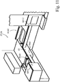
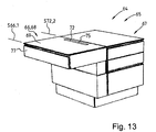
- a seventh inventive device 64 is shown in various perspective views.
- the device 64 is designed as a kitchen island 65 and is composed of a ninth height-adjustable furniture module 66 and a fixed section 67, wherein the fixed section 67 is only partially shown.
- the furniture module 66 is designed as a table 68.
- the furniture module 66 comprises, in its working surface 69 forming a top side, an opening 70 which leads into a receiving space 71 of the furniture module 66 indicated by dashed lines.
- the furniture module 66 further comprises a shelf body 72 and a second lifting device 73, wherein the shelf body 72 from the illustrated, extended position S72.3 by means of the second lifting device 73 downwardly into the receiving space 71, which is formed in an interior 74 of the furniture module 66 , can be retracted that a topsoil 75 of the schematically shown shelf body 72 rests on the working surface 69.
- a first lifting device 76 which raises and lowers a boom body 77 of the furniture module 66 is indicated only schematically.
- the boom body 77 is in the FIG. 12 in its lowest position S66.2. In the FIG. 13 the boom body 77 is in a middle position S66.1, wherein the shelf body 72 is in a fully retracted position S72.2. In the FIG. 14 the boom body 77 is then in its uppermost position S66.3 and the shelf body 72 remains in its fully retracted position S72.2.
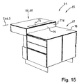
- FIG. 15 finally shows a rear view on the representation of FIG. 14 ,
- the boom body 77 of the height-adjustable furniture module 66 projects beyond a working surface 78 of the stationary section 67 of the kitchen island 65 in its uppermost position S66.3.
- the furniture module 66 and its boom body 77 is completely covered and protected on a back 79 by a rear cheek 77, so that it can be generated without dangerous shearing and without the overall impression is impaired, that is easily possible Furniture module 66 on the back of other furniture modules as example, the fixed section 67 connects and is moved in its height beyond this.
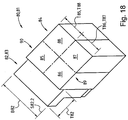
- FIGS. 16 to 18 An eighth device 80 according to the invention is shown in perspective views.
- the device 80 is designed as a kitchen island 81 and, in addition to a height-adjustable furniture module 82 according to the invention, which is designed as a table 83, a fixed portion 84.
- the fixed portion is optionally by four individual modules 85, 86, 87 and 88 or by two double modules 89th 90, which are covered by a common cover plate, not shown.
- a width B82 of the furniture module is adapted to a depth T85 to T88 or T89, T90 of the single or double modules 85 to 90 such that the width B82 corresponds to twice the depth.
- the furniture module 82 is shown in a middle position S82.1, in an uppermost position S82.3 and in a lowermost position S82.2.
- a depth T82 of the furniture module 82 corresponds to the depths T85 - T90 of the single or double modules 85 to 90, so that they can also be grouped together in series.
Landscapes
- Combinations Of Kitchen Furniture (AREA)
- Legs For Furniture In General (AREA)
Claims (10)
- Module de meuble (3 ; 31 ; 33 ; 41 ; 51 ; 53 ; 59 ; 61 ; 66 ; 82) pour une cuisine et/ou une salle de bains comprenant :- un corps de socle (6),- un caisson télescopique (7),- un corps à flèche (8) et- un dispositif de levage (9 ; 76),- le corps de socle (6) étant conçu comme un composant parallélépipédique du module de meuble (3 ; 31 ; 33 ; 41 ; 51 ; 51 ; 53 ; 59 ; 61 ; 66 ; 82), qui comprend un espace interne,- le corps à flèche (8) étant conçu comme un composant parallélépipédique du module de meuble (3 ; 31 ; 33 ; 41 ; 51 ; 51 ; 53 ; 59 ; 61 ; 66 ; 82), qui comprend un espace interne,- le dispositif de levage (9 ; 76) étant disposé entre le corps de socle (6) et le corps à flèche (8),- le dispositif de levage (9 ; 76) traversant au moins partiellement le caisson télescopique (7),- le dispositif de levage (9 ; 76) déplaçant le corps à flèche (8) vers le haut et vers le bas par rapport au corps de socle (6),- le module de meuble (3 ; 31 ; 33 ; 41 ; 51 ; 51 ; 53 ; 59 ; 61 ; 66 ; 82) comprenant un dispositif à garniture (10),- le dispositif à garniture (10) étant disposé entre le dispositif de levage (9 ; 76) et le corps à flèche (8 ; 77),- le corps à flèche (8 ; 77) pouvant être déplacé par le dispositif à garniture (10) par rapport au dispositif de levage (9 ; 76) dans un plan horizontal (E11) et/ou- le corps à flèche (8 ; 77) pouvant être pivoté par le dispositif à garniture (10) par rapport au dispositif de levage (9 ; 76) autour d'un, de préférence deux et plus particulièrement trois axes spatiaux orthogonaux entre eux (Dx, Dy, Dz).
- Module de meuble selon la revendication 1, caractérisé en ce que le caisson télescopique (7) est relié avec le corps à flèche (8 ; 78) et est déplacé par le dispositif de levage (9 ; 76) conjointement avec le corps à flèche (8 ; 78) et en ce que le caisson télescopique (7) est guidé par le corps de socle (6) et plus particulièrement dans le corps de socle (6) de manière mobile verticalement.
- Module de meuble selon la revendication 1 ou 2, caractérisé en ce que le corps à flèche (8 ; 78) est obturé vers l'avant, sur les côtés et vers l'arrière ou en ce que le corps à flèche (8) est obturé sur son côté arrière (14 ; 79).
- Module de meuble selon la revendication 1 ou 2, caractérisé en ce que le caisson télescopique (7) et/ou le corps de socle (6) est obturé vers l'avant, sur les côtés et vers l'arrière.
- Module de meuble selon l'une des revendications précédentes, caractérisé en ce que le corps de socle (6), avec le dispositif de levage (9 ; 76) disposé à l'intérieur, est soit- relié en tant que socle libre exclusivement avec un fond d'un espace dans lequel le module de meuble (3 ; 31 ; 33 ; 41 ; 51 ; 53 ; 59 ; 61 ; 66 ; 82) est disposé, soit- relié en tant que socle solidaire d'une paroi exclusivement avec une paroi d'un espace dans lequel le module de meuble (3 ; 31 ; 33 ; 41 ; 51 ; 53 ; 59 ; 61 ; 66 ; 82) est disposé soit- relié avec un fond et une paroi d'un espace dans lequel le module de meuble (3 ; 31 ; 33 ; 41 ; 51 ; 53 ; 59 ; 61 ; 66 ; 82) est disposé soit- relié debout sur le fond avec une paroi d'un espace dans lequel le module de meuble (3 ; 31 ; 33 ; 41 ; 51 ; 53 ; 59 ; 61 ; 66 ; 82) est disposé soit- relié debout sur le fond avec une joue d'un module de meuble (4 ; 24 ; 43 - 46 ; 85 - 90) adjacent.
- Module de meuble selon l'une des revendications précédentes, caractérisé en ce que le corps à flèche (8 ; 78) du module de meuble (3 ; 31 ; 33 ; 41 ; 51 ; 53 ; 59 ; 61 ; 66 ; 82) présente une largeur (B3) et une profondeur (T3) correspondantes entre elles.
- Module de meuble selon l'une des revendications précédentes, caractérisé en ce que le corps à flèche (8 ; 78) peut être déplacé de façon à ce que son côté supérieur (12) puisse être utilisé, dans sa position inférieure (S31.2 ; S41.2 ; S59.2 ; S61.2 ; S66.2 ; S82.2), en tant que surface de travail (11 ; 48), plus particulièrement à une hauteur de 50 cm à 120 cm et de préférence de 73 cm à 107 cm.
- Module de meuble selon l'une des revendications précédentes, caractérisé en ce que le module de meuble (3 ; 31 ; 33 ; 41 ; 51 ; 53 ; 59 ; 61 ; 66 ; 82) comprend un espace de logement (71), un corps à étagères (72) et un deuxième dispositif de levage (73), l'espace de logement (71) étant accessible par une ouverture (70) dans un côté supérieur (69) du corps à flèche (77), le corps à étagères (72) étant logé, dans sa position la plus basse (S72.2), entièrement dans l'espace de logement (71) et le corps à étagères (72) dépasse, dans sa position la plus haute (S73.3), du côté supérieur (69) du corps à flèche (77), le deuxième dispositif de levage (73) étant disposé plus particulièrement en dessous ou à côté du corps à étagères (72) et plus particulièrement entre le corps à étagères (72) et le caisson télescopique ou entre le corps à étagères (72) et le corps de socle.
- Dispositif, plus particulièrement dispositif de cuisine et/ou dispositif de salle de bains, caractérisé en ce que la cuisine ou la salle de bains comprend au moins un module de meuble (3 ; 31 ; 33 ; 41 ; 51 ; 53 ; 59 ; 61 ; 66 ; 82) réglable en hauteur correspondant au moins à une des revendications précédentes et en ce que la cuisine ou la salle de bains comprend au moins un module de meuble (4 ; 24 ; 43 - 46 ; 85 - 90) de hauteur constante.
- Dispositif selon la revendication 9, caractérisé en ce que le ou un des modules de meubles (3 ; 31 ; 33 ; 41 ; 51 ; 53 ; 59 ; 61 ; 66 ; 82) réglable en hauteur est disposé entre deux modules de meubles (4 ; 24 ; 43 - 46 ; 85 - 90) de hauteurs constantes et/ou en ce que le ou un des modules de meubles (3 ; 31 ; 33 ; 41 ; 51 ; 53 ; 59 ; 61 ; 66 ; 82) réglables en hauteur prolonge, avec un côté arrière (14 ; 79), un côté de joue (13) d'un module de meuble (4 ; 24 ; 43 - 46 ; 85 - 90) de hauteur constante, le module de meuble (3 ; 31 ; 33 ; 41 ; 51 ; 53 ; 59 ; 61 ; 66 ; 82) réglable en hauteur étant fixé au module de meuble (4 ; 24 ; 43 - 46 ; 85 - 90) de hauteur constante et/ou à une paroi (15) contre laquelle le module de meuble (4 ; 24 ; 43 - 46 ; 85 - 90) de hauteur constante s'appuie avec son côté arrière.
Applications Claiming Priority (3)
| Application Number | Priority Date | Filing Date | Title |
|---|---|---|---|
| DE202012101785U DE202012101785U1 (de) | 2012-05-15 | 2012-05-15 | Höhenverstellbares Möbel |
| DE102012009994A DE102012009994A1 (de) | 2012-05-22 | 2012-05-22 | Möbelmodul |
| PCT/EP2013/001430 WO2013170957A1 (fr) | 2012-05-15 | 2013-05-15 | Module de meuble |
Publications (2)
| Publication Number | Publication Date |
|---|---|
| EP2849608A1 EP2849608A1 (fr) | 2015-03-25 |
| EP2849608B1 true EP2849608B1 (fr) | 2017-07-12 |
Family
ID=49583181
Family Applications (1)
| Application Number | Title | Priority Date | Filing Date |
|---|---|---|---|
| EP13722292.3A Not-in-force EP2849608B1 (fr) | 2012-05-15 | 2013-05-15 | Module de meuble |
Country Status (2)
| Country | Link |
|---|---|
| EP (1) | EP2849608B1 (fr) |
| WO (1) | WO2013170957A1 (fr) |
Families Citing this family (1)
| Publication number | Priority date | Publication date | Assignee | Title |
|---|---|---|---|---|
| CN107374095A (zh) * | 2017-09-18 | 2017-11-24 | 张博勋 | 一种新型护理医疗用床头柜 |
Citations (1)
| Publication number | Priority date | Publication date | Assignee | Title |
|---|---|---|---|---|
| US20050275322A1 (en) * | 2004-06-09 | 2005-12-15 | Spectrum Industries Inc. | Wheelchair accommodating system |
Family Cites Families (8)
| Publication number | Priority date | Publication date | Assignee | Title |
|---|---|---|---|---|
| DE4001382A1 (de) | 1989-06-09 | 1990-12-13 | Leicht Einbaukuechen Gmbh | Kuechenarbeitseinheit |
| US5461974A (en) * | 1991-08-19 | 1995-10-31 | Reneau; Raymond P. | Workstation with integrated computer |
| US5339750A (en) * | 1992-03-27 | 1994-08-23 | Hamilton Industries | Adjustable work table |
| NL1007024C2 (nl) * | 1997-06-11 | 1998-12-14 | Pronk Ergo B V | In hoogte verstelbaar keukenblok. |
| DE20007922U1 (de) * | 2000-05-03 | 2000-08-31 | Alfred Kiess GmbH, 70567 Stuttgart | Ausfahrbare Vorrichtung für Küchenmöbel |
| WO2006115000A1 (fr) * | 2005-04-18 | 2006-11-02 | Matsushita Electric Works, Ltd. | Dispositif de detection de position de mouvement et dispositif de stockage du type elevateur |
| US20070261608A1 (en) * | 2006-05-10 | 2007-11-15 | Yun-Chi Hu | Table structure |
| AT10095U1 (de) | 2007-05-18 | 2008-09-15 | Team 7 Natuerlich Wohnen Gmbh | Vorrichtung zur höhenverstellung einer arbeitsplatte eines küchenmöbels |
-
2013
- 2013-05-15 EP EP13722292.3A patent/EP2849608B1/fr not_active Not-in-force
- 2013-05-15 WO PCT/EP2013/001430 patent/WO2013170957A1/fr not_active Ceased
Patent Citations (1)
| Publication number | Priority date | Publication date | Assignee | Title |
|---|---|---|---|---|
| US20050275322A1 (en) * | 2004-06-09 | 2005-12-15 | Spectrum Industries Inc. | Wheelchair accommodating system |
Also Published As
| Publication number | Publication date |
|---|---|
| EP2849608A1 (fr) | 2015-03-25 |
| WO2013170957A1 (fr) | 2013-11-21 |
Similar Documents
| Publication | Publication Date | Title |
|---|---|---|
| AT511099B1 (de) | Möbel mit einem möbelkorpus und einer faltklappe | |
| DE102012009994A1 (de) | Möbelmodul | |
| EP2849608B1 (fr) | Module de meuble | |
| EP2664252B1 (fr) | Meuble réglable en hauteur | |
| DE60211640T2 (de) | Schrankeinbauanordnung für eine Geschirrspülmaschine | |
| EP2786674B1 (fr) | Meuble de cuisine avec plateau de travail déplaçable | |
| EP3624637B1 (fr) | Mécanisme de levage, meuble ou appareil ménager et tiroir | |
| EP2941148B1 (fr) | Positionnement de corps d'un module meuble | |
| EP2250935B1 (fr) | Tiroir vertical pour armoire | |
| EP3029383B1 (fr) | Hotte aspirante | |
| EP1972228B1 (fr) | Meuble destiné à la saisie de matériaux et/ou appareils de travail pour salles de travail ou de classe et piètement de table destiné à la saisie d'un fond d'un tel meuble | |
| DE102017001624A1 (de) | Küche | |
| AT1117U1 (de) | Küchenanordnung | |
| DE10052240B4 (de) | Anordnung von verschiebbaren Flächenelementen einer Möbelfront | |
| DE10227743C2 (de) | Methode zur Montage von Führungen für Ausziehkörbe, die vorzugsweise für Küchenmöbel bestimmt sind | |
| EP2712516A2 (fr) | Système de levage pour un système de poste de travail réglable en hauteur et système de poste de travail doté d'un tel système de levage | |
| DE102010007430A1 (de) | Schrankauszug | |
| DE202004008478U1 (de) | Möbel, insbesondere Schrank- oder Regalmöbel | |
| DE19545652A1 (de) | Mobile Arbeitseinrichtung mit externem Anschluß an eine Computereinheit | |
| WO2018210983A1 (fr) | Bureau muni d'une paroi | |
| DE10213640A1 (de) | Ausziehbares Gestell für Möbel, versehen mit einem Trägergehäuse zum Schutz der Gleitführungen | |
| EP1478887B1 (fr) | Appareil menager sur pied | |
| DE20010930U1 (de) | Möbelkorpus | |
| EP2183994B1 (fr) | Poste de travail | |
| DE102005056973A1 (de) | Etage mit Einhängeösen |
Legal Events
| Date | Code | Title | Description |
|---|---|---|---|
| PUAI | Public reference made under article 153(3) epc to a published international application that has entered the european phase |
Free format text: ORIGINAL CODE: 0009012 |
|
| 17P | Request for examination filed |
Effective date: 20141112 |
|
| AK | Designated contracting states |
Kind code of ref document: A1 Designated state(s): AL AT BE BG CH CY CZ DE DK EE ES FI FR GB GR HR HU IE IS IT LI LT LU LV MC MK MT NL NO PL PT RO RS SE SI SK SM TR |
|
| AX | Request for extension of the european patent |
Extension state: BA ME |
|
| DAX | Request for extension of the european patent (deleted) | ||
| 17Q | First examination report despatched |
Effective date: 20160718 |
|
| STAA | Information on the status of an ep patent application or granted ep patent |
Free format text: STATUS: EXAMINATION IS IN PROGRESS |
|
| GRAP | Despatch of communication of intention to grant a patent |
Free format text: ORIGINAL CODE: EPIDOSNIGR1 |
|
| STAA | Information on the status of an ep patent application or granted ep patent |
Free format text: STATUS: GRANT OF PATENT IS INTENDED |
|
| INTG | Intention to grant announced |
Effective date: 20170102 |
|
| GRAS | Grant fee paid |
Free format text: ORIGINAL CODE: EPIDOSNIGR3 |
|
| GRAA | (expected) grant |
Free format text: ORIGINAL CODE: 0009210 |
|
| STAA | Information on the status of an ep patent application or granted ep patent |
Free format text: STATUS: THE PATENT HAS BEEN GRANTED |
|
| AK | Designated contracting states |
Kind code of ref document: B1 Designated state(s): AL AT BE BG CH CY CZ DE DK EE ES FI FR GB GR HR HU IE IS IT LI LT LU LV MC MK MT NL NO PL PT RO RS SE SI SK SM TR |
|
| REG | Reference to a national code |
Ref country code: GB Ref legal event code: FG4D Free format text: NOT ENGLISH |
|
| REG | Reference to a national code |
Ref country code: CH Ref legal event code: EP |
|
| REG | Reference to a national code |
Ref country code: AT Ref legal event code: REF Ref document number: 907516 Country of ref document: AT Kind code of ref document: T Effective date: 20170715 |
|
| REG | Reference to a national code |
Ref country code: IE Ref legal event code: FG4D Free format text: LANGUAGE OF EP DOCUMENT: GERMAN |
|
| REG | Reference to a national code |
Ref country code: DE Ref legal event code: R096 Ref document number: 502013007744 Country of ref document: DE |
|
| REG | Reference to a national code |
Ref country code: NL Ref legal event code: MP Effective date: 20170712 |
|
| REG | Reference to a national code |
Ref country code: LT Ref legal event code: MG4D |
|
| PG25 | Lapsed in a contracting state [announced via postgrant information from national office to epo] |
Ref country code: NL Free format text: LAPSE BECAUSE OF FAILURE TO SUBMIT A TRANSLATION OF THE DESCRIPTION OR TO PAY THE FEE WITHIN THE PRESCRIBED TIME-LIMIT Effective date: 20170712 Ref country code: HR Free format text: LAPSE BECAUSE OF FAILURE TO SUBMIT A TRANSLATION OF THE DESCRIPTION OR TO PAY THE FEE WITHIN THE PRESCRIBED TIME-LIMIT Effective date: 20170712 Ref country code: NO Free format text: LAPSE BECAUSE OF FAILURE TO SUBMIT A TRANSLATION OF THE DESCRIPTION OR TO PAY THE FEE WITHIN THE PRESCRIBED TIME-LIMIT Effective date: 20171012 Ref country code: FI Free format text: LAPSE BECAUSE OF FAILURE TO SUBMIT A TRANSLATION OF THE DESCRIPTION OR TO PAY THE FEE WITHIN THE PRESCRIBED TIME-LIMIT Effective date: 20170712 Ref country code: LT Free format text: LAPSE BECAUSE OF FAILURE TO SUBMIT A TRANSLATION OF THE DESCRIPTION OR TO PAY THE FEE WITHIN THE PRESCRIBED TIME-LIMIT Effective date: 20170712 Ref country code: SE Free format text: LAPSE BECAUSE OF FAILURE TO SUBMIT A TRANSLATION OF THE DESCRIPTION OR TO PAY THE FEE WITHIN THE PRESCRIBED TIME-LIMIT Effective date: 20170712 |
|
| PG25 | Lapsed in a contracting state [announced via postgrant information from national office to epo] |
Ref country code: ES Free format text: LAPSE BECAUSE OF FAILURE TO SUBMIT A TRANSLATION OF THE DESCRIPTION OR TO PAY THE FEE WITHIN THE PRESCRIBED TIME-LIMIT Effective date: 20170712 Ref country code: GR Free format text: LAPSE BECAUSE OF FAILURE TO SUBMIT A TRANSLATION OF THE DESCRIPTION OR TO PAY THE FEE WITHIN THE PRESCRIBED TIME-LIMIT Effective date: 20171013 Ref country code: RS Free format text: LAPSE BECAUSE OF FAILURE TO SUBMIT A TRANSLATION OF THE DESCRIPTION OR TO PAY THE FEE WITHIN THE PRESCRIBED TIME-LIMIT Effective date: 20170712 Ref country code: IS Free format text: LAPSE BECAUSE OF FAILURE TO SUBMIT A TRANSLATION OF THE DESCRIPTION OR TO PAY THE FEE WITHIN THE PRESCRIBED TIME-LIMIT Effective date: 20171112 Ref country code: LV Free format text: LAPSE BECAUSE OF FAILURE TO SUBMIT A TRANSLATION OF THE DESCRIPTION OR TO PAY THE FEE WITHIN THE PRESCRIBED TIME-LIMIT Effective date: 20170712 Ref country code: BG Free format text: LAPSE BECAUSE OF FAILURE TO SUBMIT A TRANSLATION OF THE DESCRIPTION OR TO PAY THE FEE WITHIN THE PRESCRIBED TIME-LIMIT Effective date: 20171012 Ref country code: PL Free format text: LAPSE BECAUSE OF FAILURE TO SUBMIT A TRANSLATION OF THE DESCRIPTION OR TO PAY THE FEE WITHIN THE PRESCRIBED TIME-LIMIT Effective date: 20170712 |
|
| REG | Reference to a national code |
Ref country code: DE Ref legal event code: R097 Ref document number: 502013007744 Country of ref document: DE |
|
| PG25 | Lapsed in a contracting state [announced via postgrant information from national office to epo] |
Ref country code: CZ Free format text: LAPSE BECAUSE OF FAILURE TO SUBMIT A TRANSLATION OF THE DESCRIPTION OR TO PAY THE FEE WITHIN THE PRESCRIBED TIME-LIMIT Effective date: 20170712 Ref country code: DK Free format text: LAPSE BECAUSE OF FAILURE TO SUBMIT A TRANSLATION OF THE DESCRIPTION OR TO PAY THE FEE WITHIN THE PRESCRIBED TIME-LIMIT Effective date: 20170712 Ref country code: RO Free format text: LAPSE BECAUSE OF FAILURE TO SUBMIT A TRANSLATION OF THE DESCRIPTION OR TO PAY THE FEE WITHIN THE PRESCRIBED TIME-LIMIT Effective date: 20170712 |
|
| PLBE | No opposition filed within time limit |
Free format text: ORIGINAL CODE: 0009261 |
|
| STAA | Information on the status of an ep patent application or granted ep patent |
Free format text: STATUS: NO OPPOSITION FILED WITHIN TIME LIMIT |
|
| PG25 | Lapsed in a contracting state [announced via postgrant information from national office to epo] |
Ref country code: SK Free format text: LAPSE BECAUSE OF FAILURE TO SUBMIT A TRANSLATION OF THE DESCRIPTION OR TO PAY THE FEE WITHIN THE PRESCRIBED TIME-LIMIT Effective date: 20170712 Ref country code: IT Free format text: LAPSE BECAUSE OF FAILURE TO SUBMIT A TRANSLATION OF THE DESCRIPTION OR TO PAY THE FEE WITHIN THE PRESCRIBED TIME-LIMIT Effective date: 20170712 Ref country code: EE Free format text: LAPSE BECAUSE OF FAILURE TO SUBMIT A TRANSLATION OF THE DESCRIPTION OR TO PAY THE FEE WITHIN THE PRESCRIBED TIME-LIMIT Effective date: 20170712 Ref country code: SM Free format text: LAPSE BECAUSE OF FAILURE TO SUBMIT A TRANSLATION OF THE DESCRIPTION OR TO PAY THE FEE WITHIN THE PRESCRIBED TIME-LIMIT Effective date: 20170712 |
|
| 26N | No opposition filed |
Effective date: 20180413 |
|
| PG25 | Lapsed in a contracting state [announced via postgrant information from national office to epo] |
Ref country code: SI Free format text: LAPSE BECAUSE OF FAILURE TO SUBMIT A TRANSLATION OF THE DESCRIPTION OR TO PAY THE FEE WITHIN THE PRESCRIBED TIME-LIMIT Effective date: 20170712 |
|
| PG25 | Lapsed in a contracting state [announced via postgrant information from national office to epo] |
Ref country code: MT Free format text: LAPSE BECAUSE OF FAILURE TO SUBMIT A TRANSLATION OF THE DESCRIPTION OR TO PAY THE FEE WITHIN THE PRESCRIBED TIME-LIMIT Effective date: 20170712 |
|
| REG | Reference to a national code |
Ref country code: CH Ref legal event code: PL |
|
| GBPC | Gb: european patent ceased through non-payment of renewal fee |
Effective date: 20180515 |
|
| REG | Reference to a national code |
Ref country code: BE Ref legal event code: MM Effective date: 20180531 |
|
| PG25 | Lapsed in a contracting state [announced via postgrant information from national office to epo] |
Ref country code: MC Free format text: LAPSE BECAUSE OF FAILURE TO SUBMIT A TRANSLATION OF THE DESCRIPTION OR TO PAY THE FEE WITHIN THE PRESCRIBED TIME-LIMIT Effective date: 20170712 |
|
| REG | Reference to a national code |
Ref country code: IE Ref legal event code: MM4A |
|
| PG25 | Lapsed in a contracting state [announced via postgrant information from national office to epo] |
Ref country code: CH Free format text: LAPSE BECAUSE OF NON-PAYMENT OF DUE FEES Effective date: 20180531 Ref country code: LI Free format text: LAPSE BECAUSE OF NON-PAYMENT OF DUE FEES Effective date: 20180531 |
|
| PG25 | Lapsed in a contracting state [announced via postgrant information from national office to epo] |
Ref country code: LU Free format text: LAPSE BECAUSE OF NON-PAYMENT OF DUE FEES Effective date: 20180515 |
|
| PG25 | Lapsed in a contracting state [announced via postgrant information from national office to epo] |
Ref country code: GB Free format text: LAPSE BECAUSE OF NON-PAYMENT OF DUE FEES Effective date: 20180515 Ref country code: FR Free format text: LAPSE BECAUSE OF NON-PAYMENT OF DUE FEES Effective date: 20180531 Ref country code: IE Free format text: LAPSE BECAUSE OF NON-PAYMENT OF DUE FEES Effective date: 20180515 |
|
| PG25 | Lapsed in a contracting state [announced via postgrant information from national office to epo] |
Ref country code: BE Free format text: LAPSE BECAUSE OF NON-PAYMENT OF DUE FEES Effective date: 20180531 |
|
| REG | Reference to a national code |
Ref country code: AT Ref legal event code: MM01 Ref document number: 907516 Country of ref document: AT Kind code of ref document: T Effective date: 20180515 |
|
| PG25 | Lapsed in a contracting state [announced via postgrant information from national office to epo] |
Ref country code: AT Free format text: LAPSE BECAUSE OF NON-PAYMENT OF DUE FEES Effective date: 20180515 |
|
| PG25 | Lapsed in a contracting state [announced via postgrant information from national office to epo] |
Ref country code: TR Free format text: LAPSE BECAUSE OF FAILURE TO SUBMIT A TRANSLATION OF THE DESCRIPTION OR TO PAY THE FEE WITHIN THE PRESCRIBED TIME-LIMIT Effective date: 20170712 |
|
| PG25 | Lapsed in a contracting state [announced via postgrant information from national office to epo] |
Ref country code: PT Free format text: LAPSE BECAUSE OF FAILURE TO SUBMIT A TRANSLATION OF THE DESCRIPTION OR TO PAY THE FEE WITHIN THE PRESCRIBED TIME-LIMIT Effective date: 20170712 Ref country code: HU Free format text: LAPSE BECAUSE OF FAILURE TO SUBMIT A TRANSLATION OF THE DESCRIPTION OR TO PAY THE FEE WITHIN THE PRESCRIBED TIME-LIMIT; INVALID AB INITIO Effective date: 20130515 |
|
| PG25 | Lapsed in a contracting state [announced via postgrant information from national office to epo] |
Ref country code: MK Free format text: LAPSE BECAUSE OF NON-PAYMENT OF DUE FEES Effective date: 20170712 Ref country code: CY Free format text: LAPSE BECAUSE OF FAILURE TO SUBMIT A TRANSLATION OF THE DESCRIPTION OR TO PAY THE FEE WITHIN THE PRESCRIBED TIME-LIMIT Effective date: 20170712 |
|
| PG25 | Lapsed in a contracting state [announced via postgrant information from national office to epo] |
Ref country code: AL Free format text: LAPSE BECAUSE OF FAILURE TO SUBMIT A TRANSLATION OF THE DESCRIPTION OR TO PAY THE FEE WITHIN THE PRESCRIBED TIME-LIMIT Effective date: 20170712 |
|
| PGFP | Annual fee paid to national office [announced via postgrant information from national office to epo] |
Ref country code: DE Payment date: 20220519 Year of fee payment: 10 |
|
| REG | Reference to a national code |
Ref country code: DE Ref legal event code: R119 Ref document number: 502013007744 Country of ref document: DE |
|
| PG25 | Lapsed in a contracting state [announced via postgrant information from national office to epo] |
Ref country code: DE Free format text: LAPSE BECAUSE OF NON-PAYMENT OF DUE FEES Effective date: 20231201 |