EP2849645B1 - Dispositif et procédé pour déterminer les erreurs de positionnement dans la réalisation de prothèses - Google Patents
Dispositif et procédé pour déterminer les erreurs de positionnement dans la réalisation de prothèses Download PDFInfo
- Publication number
- EP2849645B1 EP2849645B1 EP13722289.9A EP13722289A EP2849645B1 EP 2849645 B1 EP2849645 B1 EP 2849645B1 EP 13722289 A EP13722289 A EP 13722289A EP 2849645 B1 EP2849645 B1 EP 2849645B1
- Authority
- EP
- European Patent Office
- Prior art keywords
- angle
- extremity
- values
- prosthesis
- measurement data
- Prior art date
- Legal status (The legal status is an assumption and is not a legal conclusion. Google has not performed a legal analysis and makes no representation as to the accuracy of the status listed.)
- Active
Links
Images


Classifications
-
- A—HUMAN NECESSITIES
- A61—MEDICAL OR VETERINARY SCIENCE; HYGIENE
- A61B—DIAGNOSIS; SURGERY; IDENTIFICATION
- A61B5/00—Measuring for diagnostic purposes; Identification of persons
- A61B5/48—Other medical applications
- A61B5/4851—Prosthesis assessment or monitoring
-
- A—HUMAN NECESSITIES
- A61—MEDICAL OR VETERINARY SCIENCE; HYGIENE
- A61B—DIAGNOSIS; SURGERY; IDENTIFICATION
- A61B5/00—Measuring for diagnostic purposes; Identification of persons
- A61B5/103—Measuring devices for testing the shape, pattern, colour, size or movement of the body or parts thereof, for diagnostic purposes
- A61B5/11—Measuring movement of the entire body or parts thereof, e.g. head or hand tremor or mobility of a limb
- A61B5/112—Gait analysis
-
- A—HUMAN NECESSITIES
- A61—MEDICAL OR VETERINARY SCIENCE; HYGIENE
- A61B—DIAGNOSIS; SURGERY; IDENTIFICATION
- A61B5/00—Measuring for diagnostic purposes; Identification of persons
- A61B5/103—Measuring devices for testing the shape, pattern, colour, size or movement of the body or parts thereof, for diagnostic purposes
- A61B5/11—Measuring movement of the entire body or parts thereof, e.g. head or hand tremor or mobility of a limb
- A61B5/1121—Determining geometric values, e.g. centre of rotation or angular range of movement
- A61B5/1122—Determining geometric values, e.g. centre of rotation or angular range of movement of movement trajectories
-
- A—HUMAN NECESSITIES
- A61—MEDICAL OR VETERINARY SCIENCE; HYGIENE
- A61B—DIAGNOSIS; SURGERY; IDENTIFICATION
- A61B5/00—Measuring for diagnostic purposes; Identification of persons
- A61B5/45—For evaluating or diagnosing the musculoskeletal system or teeth
- A61B5/4538—Evaluating a particular part of the muscoloskeletal system or a particular medical condition
- A61B5/4571—Evaluating the hip
-
- A—HUMAN NECESSITIES
- A61—MEDICAL OR VETERINARY SCIENCE; HYGIENE
- A61B—DIAGNOSIS; SURGERY; IDENTIFICATION
- A61B5/00—Measuring for diagnostic purposes; Identification of persons
- A61B5/45—For evaluating or diagnosing the musculoskeletal system or teeth
- A61B5/4538—Evaluating a particular part of the muscoloskeletal system or a particular medical condition
- A61B5/4585—Evaluating the knee
-
- A—HUMAN NECESSITIES
- A61—MEDICAL OR VETERINARY SCIENCE; HYGIENE
- A61B—DIAGNOSIS; SURGERY; IDENTIFICATION
- A61B5/00—Measuring for diagnostic purposes; Identification of persons
- A61B5/74—Details of notification to user or communication with user or patient; User input means
- A61B5/7405—Details of notification to user or communication with user or patient; User input means using sound
-
- A—HUMAN NECESSITIES
- A61—MEDICAL OR VETERINARY SCIENCE; HYGIENE
- A61B—DIAGNOSIS; SURGERY; IDENTIFICATION
- A61B5/00—Measuring for diagnostic purposes; Identification of persons
- A61B5/74—Details of notification to user or communication with user or patient; User input means
- A61B5/742—Details of notification to user or communication with user or patient; User input means using visual displays
-
- A—HUMAN NECESSITIES
- A61—MEDICAL OR VETERINARY SCIENCE; HYGIENE
- A61B—DIAGNOSIS; SURGERY; IDENTIFICATION
- A61B5/00—Measuring for diagnostic purposes; Identification of persons
- A61B5/74—Details of notification to user or communication with user or patient; User input means
- A61B5/746—Alarms related to a physiological condition, e.g. details of setting alarm thresholds or avoiding false alarms
Definitions
- the invention relates to a method for determining malpositions of a prosthetic foot relative to a lower leg tube in the construction of prostheses for the lower extremities, with the following steps: Determination of inertial measurement data and/or the variables derived therefrom of a supplied extremity via at least one inertial sensor on a component of the prosthesis is arranged on the lower extremity and is coupled to a comparator, over at least one gait cycle and comparing the determined inertial measurement data and/or the variables determined therefrom with target values in the comparator.
- Such a method is, for example, from U.S. 2010/131113 A1 and the U.S. 2011/313545 A1 known.
- Prostheses are generally used to replace the form and particularly the function of missing or no longer existing limbs. While the prostheses made for purely cosmetic reasons do not have to fulfill any functional tasks, prostheses on the lower and upper extremities regularly provide for the assumption of complex tasks. Hand prostheses simulate the function of a natural hand to a large extent, with the control of the motor drives in particular requiring a great deal of effort.
- Prostheses of the lower extremities regularly consist of prosthetic feet, a lower leg tube and possibly a prosthetic knee joint and are often attached to the residual stump via sockets.
- the construction of prostheses for the lower extremities is based on the needs and abilities of the patient and ranges from a uniaxial locking knee joint to computer-controlled prostheses that change the damping properties on the basis of sensor values and switch drives on or off.
- a key aspect of prosthetic care is the correct adjustment of the prosthesis to the prosthesis user and the correct assignment of the individual prosthesis components to one another.
- This alignment of the prosthesis components to one another and to the patient is called the prosthesis structure or the structure of the prosthesis in orthopedic technology.
- the adjustment and, if necessary, optimization of the settings of upper or lower leg prostheses is carried out individually for a patient by an orthopedic technician as part of the fitting process.
- the orthopedic technician orientates himself on assembly instructions as well as on his observation or the impressions of the patient.
- the display system provides a measuring plate and a projection device for visualizing a vertical measuring line on the body of a person standing on the measuring plate, with the measuring plate being fitted with pressure sensors which are connected to one another via a circuit and which control a drive which runs in a plane parallel to the measuring plate moves an optical system in such a way that a light beam indicates the current center of gravity of the person.
- the WO 2010/120402 A1 relates to a control system for controlling an associated device with an inertial measuring unit for determining the orientation of three axes with a computing unit for evaluating the sensor data.
- the sensor module is connected to the assigned device via a communication unit and can be controlled via it. conclusions on a prosthesis structure does not result from this.
- the object of the present invention is to provide a method and a device with which it is possible to easily assess the prosthesis structure using gait analysis measurement data, so that after appropriate correction an improved prosthesis structure can be provided for the patient.
- the method for determining misalignments in the structure of prostheses of the lower extremities provides that inertial measurement data and/or variables derived therefrom of a supplied extremity is determined with at least one inertial sensor over at least one gait cycle.
- a fitted limb is a limb to which a prosthetic device is attached or which is replaced by a prosthetic device.
- the typical components are a prosthetic foot and a lower leg socket, optionally a pylon to which the prosthetic foot is attached.
- a femoral socket for receiving a thigh stump, a prosthetic knee joint, a lower leg tube and a prosthetic foot are provided.
- the ascertained inertial measurement data and/or variables derived therefrom are compared with target values and/or with ascertained measurement data or derived variables for the corresponding extremity that is not treated.
- the setpoints can be stored in a memory and based on empirical values or Values that have been recorded on the patient to be cared for are based.
- the determined inertial measurement data can refer to variables in different planes. For example, angles in the sagittal plane can be determined and compared to determine how long the step is, how far the lower leg and thus the knee is bent when stepping on it, or how far the lower leg swings backwards during the swing phase.
- it is possible to determine corresponding measurement data and/or derived variables at the corresponding points on the untreated, i.e. healthy, extremity e.g. absolute angles via inertial angle sensors or accelerations via Measure acceleration sensors and base the comparison on them.
- inertial sensors In addition to the absolute angle, inertial sensors also measure the linear accelerations of the respective components that occur along the axes of a reference system, as well as the rates of rotation or angular velocities around the respective axes in order to be able to derive the rotational movements from them.
- One embodiment of the invention provides that absolute angle sensors, in particular, are used as inertial sensors, via which the absolute angle of the respective component or extremity is determined.
- the determination can be immediate take place through the sensors, so that a conversion does not have to be carried out, as is necessary to determine the derived quantity.
- the respective inertial measured value e.g. the acceleration or the absolute angle
- the respective inertial measured value can be determined both on the corresponding extremity supplied with the prosthesis and on the limb without one, whereby measured values and variables derived from them on the thigh, e.g. the thigh angle, the direction of movement, acceleration or direction of acceleration, can be determined. Attachment to the unaided limb is necessary for a direct comparison between the limbs.
- the knee angle is determined from the measured absolute angles of the lower leg and thigh and is compared with target values and/or the determined knee angle of the unsupported leg over the respective gait cycle or an average of several gait cycles.
- the start of a gait cycle can be determined using the characteristic angle profile when walking on a level surface, for example using the knee angle profile. This makes it possible to dispense with additional sensors that measure forces or moments, for example. It is therefore possible to determine whether a prosthesis construction corresponds to the desired result, in particular whether a harmonious gait pattern is possible for a patient, based on a pure angle measurement of extremities after the prosthesis has been fitted on the basis of gait dynamic measurements, without having to simply observe the movement sequence must be resorted to by an orthopedic technician.
- a further development of the invention provides that a discrepancy message is output in the event of discrepancies between the ascertained inertial measurement data or the variables derived therefrom and the stored target values and/or measurement data or variables derived therefrom of the corresponding untreated extremity.
- a confirmation message can also be issued for values within the target values or within a permissible scatter range around a target value or measured data determined or variables derived from them for the corresponding untreated extremity, so that the prosthetist and the patient receive feedback whether the static prosthesis alignment is correct or not.
- a pelvic angle within the frontal plane is determined via at least one inertial angle sensor and a deviation message is output if a limit value is exceeded.
- the tilting of the pelvic angle within the frontal plane when walking is an indication of Trendelenburg's limp. If the pelvic tilt exceeds a defined angle while walking within the frontal plane, this serves as an indication for the prosthetist that further adduction of the socket must take place.
- the inertial measurement data in particular absolute angles, to be determined over several gait cycles, for example on a treadmill or in a gait analysis device, in order to have the broadest possible database for assessing the static structure of the prosthesis, for optimizing the prosthesis structure, the adjustment of the prosthesis, the component selection and documentation.
- the quantities derived from this can also be determined and used over several gait cycles. It is also possible to better inform and instruct the patient based on the measured values or the quantities derived therefrom, so that there is an improved understanding of the relationships between the structure and behavior of the prosthesis during use improved acceptance by the patient and improved utilization of the prosthesis can be achieved.
- the inertial angle it is also possible to determine whether the external rotation angle of the knee axis is set correctly. If a rotational vibration of the supplied lower leg is detected during the swing phase, this is an indication that the knee axis is not aligned orthogonally to the direction of movement of the thigh, so that the lower leg experiences a dynamic imbalance. This dynamic imbalance can be caused by step recognition and the time allocation of the measured values within the gait phase. If a high vibration frequency of the bent lower leg is measured during the swing phase, this is an indication of an incorrect alignment of the joint axis.
- a device for carrying out a method described here with at least one inertial sensor provides that this is arranged on a component of a prosthesis of the lower extremity and is coupled to a comparator in which the determined inertial measurement data, e.g. angle, acceleration, direction with setpoint values and/or Comparison values are compared, with the target values being stored in the comparator or a corresponding database being connected to the comparator.
- the comparative values relate to values of the patient's leg without treatment, which are also stored in the comparator or made accessible to it in a database. The making accessible can take place, for example, via a radio link.
- At least one inertial sensor is attached to the unaided extremity in order to ascertain comparative values. If several inertial sensors are provided on the extremity supplied, for example on the lower leg and thigh, it is advantageous if corresponding sensors are arranged at corresponding locations on the extremity not supplied. Also these sensors are then connected to the comparator, for example by cable or via a radio link.
- the output device for the determined and possibly compared values or a discrepancy report if the values for the side supplied do not correspond to the target values or comparative values is also connected to the comparator and can be designed as an acoustic or optical output device. This makes it possible that while walking and measuring the measurement data, there is immediate feedback for both the user and the prosthetist as to whether there is a harmonious gait pattern, whether the dynamic angle profiles correspond to the specifications or target values, whether other measurement data and/or derived variables the specifications or comparative values and whether the prosthesis alignment is adjusted correctly or not.
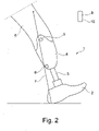
- a prosthesis 1 is shown with a prosthetic foot 2, a lower leg tube 3 attached proximally thereto and a shaft 4 which establishes a connection to the remaining lower extremity 6.
- the shaft 4 protrudes beyond the remaining knee joint, so that a knee rotation axis 5 is partially covered.
- a transtibial prosthesis is shown that has no prosthetic knee joint. Basically, they apply following explanations also for transfemoral prostheses with a prosthetic knee joint.
- the prosthetic foot 2 is arranged so that it can be displaced relative to the lower leg shaft 3, for example via a displacement adapter (not shown) or a slot guide, so that in addition to a rotation about the longitudinal extension of the lower leg tube 3, a displacement of the prosthetic foot 2 anteriorly in the walking direction or posteriorly in the opposite direction to the walking direction is also possible.
- An inertial sensor 8 in the form of an inertial angle sensor is arranged or incorporated on the shaft 4, via which the absolute angle of the prosthesis, in the present case the shaft 4 and the lower leg tube 3, can be determined relative to the vertical.
- angle sensors are provided as inertial sensors, which determine the absolute angle relative to the direction of gravity; acceleration sensors and/or yaw rate sensors can also be provided to record the inertial measurement data.
- inertial sensors for example on the thigh and hip
- these are in particular the orientation of the thigh, the orientation of the lower leg, the orientation of the hip and the flexion of the knee from the difference angle between the thigh angle and the lower leg angle in the sagittal plane.
- step recognition can be implemented, which allows the measured angle values to be assigned in time to the respective gait phase.
- a critical parameter in fitting transtibial prostheses is adequate knee flexion and adequate knee extension after heel strike. This parameter can be decisively influenced by the positioning of the prosthetic foot 2 relative to the lower leg tube 3 and thus to the shaft 4 .
- a change in the positioning of the prosthetic foot 2 in the anterior-posterior direction leads to a change in the progression of the ground reaction force 7 when stepping, rolling and at the end of the stance phase when the toe releases.
- This change in the course results in a change in the effective knee moment about the knee axis 5 , which, depending on the position of the ground reaction forces 7 , has a stretching or bending effect relative to the joint axis 5 .
- the prosthetic foot 2 is shifted maximally anteriorly, so that when the heel strikes at the beginning of the stance phase, the vector of the ground reaction force 7 is oriented anterior to the knee axis of rotation 5 .
- an orthopedic technician can conclude that prosthetic foot 2 is too far anterior is arranged so that an adjustment in the posterior direction is required. This adjustment can be made gradually until the desired knee angle is reached during normal walking.
- FIG 2 shows the maximum position of the prosthetic foot 2 in the posterior direction, with a heel strike the vector of the ground reaction force 7 runs behind the knee axis of rotation 5, so that there is a very strong bending due to the flexing knee moment. That unwanted knee bend the patient has to intercept with the supplied leg, which is disadvantageous. Therefore, the orthopedic technician will analyze the course of the angle after the heel strike and determine that the knee bends too much or too quickly and thus the shaft 4 shifts too quickly relative to the vertical. This means that the prosthetic foot 2 has to be shifted further anteriorly until the patient begins to bend the knee in a controlled manner.
- the determination of the structure via the heel strike is made easier if the knee angle is available as a measured value, so that additional inertial angle sensors 8 would have to be arranged on the thigh.
- the knee angle is calculated by taking the difference between the segment angles of the thigh and lower leg in the sagittal plane. Based on the measured knee angle curve or possibly also solely based on the measured lower leg curve for several steps, a recommendation can now be given as to the direction in which the prosthetic foot must be shifted. This recommendation can be made via an output device 10 on a comparator 9 which is connected to the sensor 8 or the sensors 8 .
- the measured angles are processed within the comparator 9 and the output command or output value is determined, if appropriate, using target curves or measured angle values of the contralateral, untreated leg.
- FIG. 3 and 4 A further indication of whether the prosthesis construction is correct or not can occur in the phase of toe detachment, the so-called "toe-off".
- Figures 3 and 4 is shown. With an orientation of the prosthetic foot 2 too far anterior according to figure 3 a knee-stretching moment is exerted due to the course of the resulting ground reaction force 7 anterior to the knee rotation axis 5, so that bending in after the toe-off is not possible or is only possible with difficulty. Accordingly, it is necessary to position the prosthetic foot 2 more posteriorly.
- the resultant ground reaction force vector 7 runs posteriorly at toe-off Knee axis of rotation 5, resulting in sudden and uncontrolled flexion or increased patient loading in the case of a transtibial prosthesis. If no knee flexion is detected at toe-off or shortly thereafter, or if the inertial angle of the shaft 4 and the thigh does not increase sufficiently, a positioning too far anterior can be assumed Positioning too far posterior can be assumed, so that an appropriate adjustment is necessary to compensate for this.
- a signal is output via the output device 10 as to whether the structure corresponds to the specifications or whether changes and which changes are to be made, ie whether a displacement is to be made anteriorly or posteriorly.
- a physiologically correct gait is characterized, among other things, by the fact that the segment angles of the thigh and lower leg of both legs describe an almost identical movement sequence and range of movement during normal walking on a level surface. If a prosthesis wearer has a reduced range of motion in the prosthesis-side thigh angle in the sagittal plane, this may indicate a flexion contracture that was not considered during prosthesis assembly. If the range of motion of the patient's right and left thigh is measured directly using inertial sensors while walking, it is possible to determine different ranges of motion due to the deviating inertial angle during a gait cycle or a step. If the range of motion on the prosthesis is less, an indication is output via the comparator 9 and the output device 10 that a flexion contracture is present, so that the prosthesis structure must be changed accordingly.
- the prosthetic foot 2 should be positioned anteriorly step by step until the knee can be easily controlled.
- the approximately physiological knee angle can be determined via the output device 10 by means of an acoustic signal.
- a negative-sounding signal can be output or an optical warning device can be activated.
- a hip flexion contracture may be more noticeable when walking than in the patient's history.
- the measurement of the thigh angle movement during walking is carried out on the prosthesis side and contralaterally in the sagittal plane.
- the socket flexion is increased within the prosthesis until the range of motion is equalized.
- transfemoral prostheses can be that the performance of the gluteus maxims is weaker than determined in the anamnesis. The external rotation of the knee axis is then less than is actually required for the individual walking style.
- the pelvic angle is measured while walking. If a tilting of the hip to position the center of gravity over the prosthesis or a sinking of the hip on the contralateral side is measured, for example greater than 5° to the horizontal, the abduction angle is gradually increased until the patient can tilt the pelvis in the range of ⁇ 5° when walking no longer leaves.
- an inertial angle measurement is also carried out on the lower leg. If, for example, an angular movement greater than 5° is measured when walking on a level surface, the knee axis 5 is gradually rotated outwards until the angular movement remains within a tolerable range.
Landscapes
- Health & Medical Sciences (AREA)
- Life Sciences & Earth Sciences (AREA)
- Physics & Mathematics (AREA)
- General Health & Medical Sciences (AREA)
- Veterinary Medicine (AREA)
- Engineering & Computer Science (AREA)
- Biomedical Technology (AREA)
- Heart & Thoracic Surgery (AREA)
- Medical Informatics (AREA)
- Molecular Biology (AREA)
- Surgery (AREA)
- Animal Behavior & Ethology (AREA)
- Biophysics (AREA)
- Public Health (AREA)
- Pathology (AREA)
- Dentistry (AREA)
- Oral & Maxillofacial Surgery (AREA)
- Physiology (AREA)
- Geometry (AREA)
- Physical Education & Sports Medicine (AREA)
- Orthopedic Medicine & Surgery (AREA)
- Rheumatology (AREA)
- Transplantation (AREA)
- Prostheses (AREA)
- Measurement Of The Respiration, Hearing Ability, Form, And Blood Characteristics Of Living Organisms (AREA)
Claims (6)
- Procédé de détermination de défauts d'alignement d'un pied prothétique (2) par rapport à un tube de jambe inférieure (3) dans la structure de prothèses des membres inférieurs, comprenant les étapes suivantes consistant à :- déterminer, par l'intermédiaire d'au moins un capteur inertiel (8) disposé sur un composant (2, 3, 4) de la prothèse du membre inférieur et couplé à un comparateur (9), des données de mesure inertielle et/ou des grandeurs, dérivées de celles-ci, d'un membre équipé, sur au moins un cycle de marche, et- comparer les données de mesure inertielle déterminées et/ou les grandeurs dérivées de celles-ci à des valeurs de consigne dans le comparateur (9),caractérisé en ce qu'un angle de genou est déterminé à partir d'un angle absolu mesuré de la jambe inférieure et d'un angle absolu mesuré d'une cuisse, et est comparé à des valeurs de consigne.
- Procédé selon la revendication 1,
caractérisé en ce que des angles absolus, des accélérations linéaires et/ou des vitesses de rotation sont mesurés comme données de mesure inertielle. - Procédé selon la revendication 1 ou 2,
caractérisé en ce que les données de mesure inertielle respectives et/ou les grandeurs dérivées de celles-ci sont déterminées aussi bien sur le membre équipé de la prothèse que sur le membre correspondant non équipé. - Procédé selon l'une des revendications précédentes,
caractérisé en ce qu'un message d'écart est émis en cas d'écarts des angles déterminés par rapport aux valeurs de consigne et/ou aux angles du membre correspondant non équipé, ou un message de confirmation est émis en cas de valeurs comprises dans les valeurs de consigne et/ou dans les valeurs déterminées pour le membre correspondant non équipé. - Procédé selon l'une des revendications précédentes,
caractérisé en ce qu'un angle du bassin dans le plan frontal est déterminé par au moins un capteur d'angle inertiel, et un message d'erreur est émis en cas de dépassement d'une valeur limite. - Procédé selon l'une des revendications précédentes,
caractérisé en ce que les données de mesure inertielle sont déterminées sur plusieurs cycles de marche.
Priority Applications (1)
| Application Number | Priority Date | Filing Date | Title |
|---|---|---|---|
| EP22207146.6A EP4162871A1 (fr) | 2012-05-14 | 2013-05-14 | Dispositif et procédé pour déterminer les erreurs de positionnement dans la réalisation de prothèses |
Applications Claiming Priority (2)
| Application Number | Priority Date | Filing Date | Title |
|---|---|---|---|
| DE102012009507A DE102012009507A1 (de) | 2012-05-14 | 2012-05-14 | Vorrichtung und Verfahren zur Bestimmung von Fehlstellungen im Aufbau von Prothesen |
| PCT/EP2013/001404 WO2013170945A1 (fr) | 2012-05-14 | 2013-05-14 | Dispositif et procédé pour déterminer les erreurs de positionnement dans la réalisation de prothèses |
Related Child Applications (1)
| Application Number | Title | Priority Date | Filing Date |
|---|---|---|---|
| EP22207146.6A Division EP4162871A1 (fr) | 2012-05-14 | 2013-05-14 | Dispositif et procédé pour déterminer les erreurs de positionnement dans la réalisation de prothèses |
Publications (2)
| Publication Number | Publication Date |
|---|---|
| EP2849645A1 EP2849645A1 (fr) | 2015-03-25 |
| EP2849645B1 true EP2849645B1 (fr) | 2022-11-16 |
Family
ID=48430656
Family Applications (2)
| Application Number | Title | Priority Date | Filing Date |
|---|---|---|---|
| EP22207146.6A Pending EP4162871A1 (fr) | 2012-05-14 | 2013-05-14 | Dispositif et procédé pour déterminer les erreurs de positionnement dans la réalisation de prothèses |
| EP13722289.9A Active EP2849645B1 (fr) | 2012-05-14 | 2013-05-14 | Dispositif et procédé pour déterminer les erreurs de positionnement dans la réalisation de prothèses |
Family Applications Before (1)
| Application Number | Title | Priority Date | Filing Date |
|---|---|---|---|
| EP22207146.6A Pending EP4162871A1 (fr) | 2012-05-14 | 2013-05-14 | Dispositif et procédé pour déterminer les erreurs de positionnement dans la réalisation de prothèses |
Country Status (4)
| Country | Link |
|---|---|
| US (2) | US10478121B2 (fr) |
| EP (2) | EP4162871A1 (fr) |
| DE (1) | DE102012009507A1 (fr) |
| WO (1) | WO2013170945A1 (fr) |
Families Citing this family (18)
| Publication number | Priority date | Publication date | Assignee | Title |
|---|---|---|---|---|
| US10531968B2 (en) * | 2014-05-23 | 2020-01-14 | Joseph Coggins | Prosthetic limb test apparatus and method |
| JP6660110B2 (ja) * | 2015-07-23 | 2020-03-04 | 原田電子工業株式会社 | 歩行解析方法および歩行解析システム |
| US11992345B2 (en) * | 2015-08-18 | 2024-05-28 | University Of Miami | Method and system for adjusting audio signals based on motion deviation |
| WO2017053899A1 (fr) * | 2015-09-23 | 2017-03-30 | Ali Kord | Dispositif de contrôle de position |
| DE102017110762A1 (de) * | 2017-05-17 | 2018-11-22 | Ottobock Se & Co. Kgaa | Verfahren zum Bestimmen von Fehlstellungen im Aufbau einer Prothese |
| US11666461B2 (en) * | 2017-05-26 | 2023-06-06 | Massachusetts Institute Of Technology | Method for design and manufacture of compliant prosthetic foot |
| DE102018128514B4 (de) * | 2018-11-14 | 2021-01-14 | Ottobock Se & Co. Kgaa | Verfahren und Vorrichtung zum Durchführen eines Prothesenaufbaus |
| WO2020247052A1 (fr) | 2019-06-03 | 2020-12-10 | Massachusetts Institute Of Technology | Optimisation de forme pour pieds prothétiques |
| DE102019118118B4 (de) * | 2019-07-04 | 2021-02-18 | Ottobock Se & Co. Kgaa | Protheseneinrichtung für eine untere Extremität, Einstelleinrichtung für eine Protheseneinrichtung sowie Verfahren zum manuellen Einstellen |
| CN111803075B (zh) * | 2020-06-24 | 2023-07-18 | 深圳市丞辉威世智能科技有限公司 | 下肢损伤的检测方法、装置、设备及计算机存储介质 |
| DE102022111332A1 (de) | 2022-05-06 | 2023-11-09 | Ottobock Se & Co. Kgaa | Verfahren zum Einrichten einer orthopädietechnischen Vorrichtung |
| DE102022111327A1 (de) | 2022-05-06 | 2023-11-09 | Ottobock Se & Co. Kgaa | Verfahren zum Einrichten einer orthopädietechnischen Einrichtung |
| DE102022116496A1 (de) | 2022-07-01 | 2024-01-04 | Otto Bock Healthcare Products Gmbh | Verfahren, Computerprogramm und System zum Einstellen einer orthopädie-technischen Versorgung |
| CN115501013A (zh) * | 2022-10-09 | 2022-12-23 | 中国人民解放军总医院第四医学中心 | 一种高度自适应调节的旋转成形术术后假肢系统 |
| TWI846580B (zh) * | 2023-08-29 | 2024-06-21 | 國立清華大學 | 步態監控與保健系統 |
| CN117012362B (zh) * | 2023-10-07 | 2024-01-12 | 中国康复科学所(中国残联残疾预防与控制研究中心) | 一种适配数据识别方法、系统、设备及存储介质 |
| DE102023129572A1 (de) | 2023-10-26 | 2025-04-30 | Ottobock Se & Co. Kgaa | Verfahren und System zum Bewegungstraining einer Bewegung |
| ES3060474A1 (es) * | 2024-09-20 | 2026-03-26 | Univ Del Pais Vasco / Euskal Herriko Unibertsitatea | Sistema y metodo para monitorizar la marcha de un usuario con protesis de pierna |
Citations (2)
| Publication number | Priority date | Publication date | Assignee | Title |
|---|---|---|---|---|
| US20100131113A1 (en) * | 2007-05-03 | 2010-05-27 | Motek Bv | Method and system for real time interactive dynamic alignment of prosthetics |
| US20110313545A1 (en) * | 2006-09-11 | 2011-12-22 | Orthocare Innovations Llc | Method for aligning a prosthesis |
Family Cites Families (31)
| Publication number | Priority date | Publication date | Assignee | Title |
|---|---|---|---|---|
| US1285805A (en) | 1918-07-26 | 1918-11-26 | Vincent Scarperi | Propeller-post construction. |
| US4306571A (en) * | 1980-03-31 | 1981-12-22 | Orthopaedic Research Institute, Inc. | Dynamic joint motion analysis technique |
| US4488441A (en) | 1983-04-15 | 1984-12-18 | Jr3, Inc. | Apparatus for simultaneous measurement of mutually perpendicular forces and moments |
| US4640138A (en) | 1985-03-06 | 1987-02-03 | Mts Systems Corporation | Multiple axis load sensitive transducer |
| US4849730A (en) | 1986-02-14 | 1989-07-18 | Ricoh Company, Ltd. | Force detecting device |
| DE3701372A1 (de) | 1987-01-19 | 1988-07-28 | Bayerische Motoren Werke Ag | Flaechenfoermiger kraftaufnehmer |
| EP0575634B1 (fr) | 1992-05-25 | 1996-10-09 | Hottinger Baldwin Messtechnik Gmbh | Palpeur de couple |
| DE4401036C2 (de) | 1994-01-15 | 2000-04-06 | Bock Orthopaed Ind | Anzeigesystem zur Vermessung des menschlichen Körpers |
| DE4412377A1 (de) | 1994-04-13 | 1995-10-19 | Hottinger Messtechnik Baldwin | Aufnehmer zum Messen von Belastungen |
| US5490427A (en) | 1994-10-17 | 1996-02-13 | Fanuc Usa Corporation | Six axis force sensor employing multiple shear strain gages |
| US6105438A (en) | 1998-09-11 | 2000-08-22 | The United States Of America As Represented By The Secretary Of The Navy | Reconfigurable multiple component load measuring device |
| CA2347796C (fr) | 1998-10-30 | 2009-12-29 | Vernon A. Lambson | Procede et appareil de mesure de couple |
| DE19859931A1 (de) * | 1998-12-24 | 2000-07-06 | Biedermann Motech Gmbh | Beinprothese mit einem künstlichen Kniegelenk und Verfahren zur Steuerung einer Beinprothese |
| US6774885B1 (en) * | 1999-01-20 | 2004-08-10 | Motek B.V. | System for dynamic registration, evaluation, and correction of functional human behavior |
| DE10013059C2 (de) | 2000-03-19 | 2002-01-31 | Deutsch Zentr Luft & Raumfahrt | Kraft-Momenten-Sensor |
| WO2001072245A2 (fr) | 2000-03-29 | 2001-10-04 | Massachusetts Institute Of Technology | Prothese de genou adaptable a la vitesse et adaptable au patient |
| DE10139333A1 (de) | 2001-08-10 | 2003-03-06 | Biedermann Motech Gmbh | Sensoreinrichtung, insbesondere für eine Prothese und Prothese mit einer solchen Sensoreinrichtung |
| JP4192084B2 (ja) | 2003-06-17 | 2008-12-03 | ニッタ株式会社 | 多軸センサ |
| DE102004004678B4 (de) | 2004-01-29 | 2005-12-29 | Otto Bock Healthcare Gmbh | Drehmomentsensor |
| US7811334B2 (en) * | 2004-02-12 | 2010-10-12 | Ossur Hf. | System and method for motion-controlled foot unit |
| CA2595895C (fr) * | 2005-02-02 | 2016-06-14 | Ossur Hf | Systemes et procedes de detection pour la surveillance de la dynamique de marche |
| DE102005051646A1 (de) * | 2005-10-26 | 2007-05-10 | Otto Bock Healthcare Ip Gmbh & Co. Kg | Verfahren zur Überprüfung der Einstellung eines Prothesenkniegelenks |
| DE102005051495A1 (de) | 2005-10-26 | 2007-05-03 | Otto Bock Healthcare Ip Gmbh & Co. Kg | Sensoranordnung für die Messung von Kräften und/oder Momenten und Verwendung der Sensoranordnung |
| US8298293B2 (en) * | 2006-04-28 | 2012-10-30 | College Park Industries, Inc. | Prosthetic sensing systems and methods |
| EP1970005B1 (fr) | 2007-03-15 | 2012-10-03 | Xsens Holding B.V. | Système et procédé du suivi du mouvement en utilisant une unité d'étalonnage |
| WO2009114909A1 (fr) * | 2008-03-19 | 2009-09-24 | Murdoch Childrens Research Institute | Analyse de mouvement |
| GB0820874D0 (en) * | 2008-11-14 | 2008-12-24 | Europ Technology For Business | Assessment of gait |
| CA2761806C (fr) | 2009-04-13 | 2017-08-15 | Deka Products Limited Partnership | Systeme et appareil pour commande d'orientation |
| US9017418B2 (en) * | 2009-05-05 | 2015-04-28 | össur hf | Control systems and methods for prosthetic or orthotic devices |
| WO2012050908A2 (fr) * | 2010-09-28 | 2012-04-19 | Orthocare Innovations Llc | Système informatisé de prescription orthétique |
| EP2621414B1 (fr) * | 2010-09-29 | 2019-03-13 | Össur HF | Dispositifs prosthétiques et orthétiques et procédés et systèmes pour commander ceux-ci |
-
2012
- 2012-05-14 DE DE102012009507A patent/DE102012009507A1/de active Pending
-
2013
- 2013-05-14 EP EP22207146.6A patent/EP4162871A1/fr active Pending
- 2013-05-14 EP EP13722289.9A patent/EP2849645B1/fr active Active
- 2013-05-14 WO PCT/EP2013/001404 patent/WO2013170945A1/fr not_active Ceased
- 2013-05-14 US US14/401,400 patent/US10478121B2/en active Active
-
2019
- 2019-11-18 US US16/687,495 patent/US20200093432A1/en not_active Abandoned
Patent Citations (2)
| Publication number | Priority date | Publication date | Assignee | Title |
|---|---|---|---|---|
| US20110313545A1 (en) * | 2006-09-11 | 2011-12-22 | Orthocare Innovations Llc | Method for aligning a prosthesis |
| US20100131113A1 (en) * | 2007-05-03 | 2010-05-27 | Motek Bv | Method and system for real time interactive dynamic alignment of prosthetics |
Also Published As
| Publication number | Publication date |
|---|---|
| US10478121B2 (en) | 2019-11-19 |
| WO2013170945A1 (fr) | 2013-11-21 |
| US20200093432A1 (en) | 2020-03-26 |
| DE102012009507A1 (de) | 2013-11-14 |
| EP4162871A1 (fr) | 2023-04-12 |
| EP2849645A1 (fr) | 2015-03-25 |
| US20150133821A1 (en) | 2015-05-14 |
Similar Documents
| Publication | Publication Date | Title |
|---|---|---|
| EP2849645B1 (fr) | Dispositif et procédé pour déterminer les erreurs de positionnement dans la réalisation de prothèses | |
| EP2816979B1 (fr) | Procédé de commande d'une articulation de genou artificielle d'une orthèse ou prothèse | |
| EP1940327B1 (fr) | Procédé de surveillance du réglage et réglage d'une prothèse de membre inferieur, ainsi que procédé de mesure de forces ou de couples dans une prothèse de membre inferieur | |
| DE102013013810B3 (de) | Verfahren zur Steuerung eines künstlichen Orthesen- oder Prothesenkniegelenkes | |
| DE102020004339B4 (de) | Verfahren zur Steuerung einer Prothese oder Orthese | |
| DE102008024746A1 (de) | Orthopädietechnische Einrichtung | |
| EP3858297A1 (fr) | Dispositif technique orthopédique | |
| WO2022063826A1 (fr) | Procédé de commande d'une prothèse de pied | |
| EP3911282B1 (fr) | Procédé pour la commande d'un dispositif orthétique ou prothétique et dispositif orthétique ou prothétique | |
| EP4447873A1 (fr) | Dispositif orthopédique et son procédé de production | |
| EP4017425B1 (fr) | Procédé de fabrication d'une emboîture de prothèse | |
| DE102016107743A1 (de) | Verfahren zur Steuerung einer Antriebs- und/oder Bremseinrichtung eines orthetischen oder prothetischen, künstlichen Gelenks | |
| DE102020004338B4 (de) | Verfahren zur Steuerung einer Prothese oder Orthese | |
| EP4181838A2 (fr) | Procédé de commande d'une prothèse ou orthèse | |
| DE102021115467A1 (de) | Verfahren, Vorrichtung und Computerprogramm zum Erstellen von Fertigungsdaten für ein orthopädietechnisches Produkt | |
| WO2018215921A1 (fr) | Prothèse articulaire | |
| DE102021133616A1 (de) | Verfahren zur Steuerung eines prothetischen und/oder orthetischen Systems und ein solches System | |
| WO2023214028A1 (fr) | Procédé de mise en place d'un dispositif orthopédique | |
| EP4518809B1 (fr) | Procédure d'installation d'un appareillage orthopédique | |
| WO2025088137A1 (fr) | Procédé et système de formation en mouvements d'un mouvement | |
| DE102005008605A1 (de) | Verfahren zur Herstellung einer äußeren Prothese oder Orthese | |
| DE102023135288A1 (de) | Verfahren zur Steuerung einer Feedbackeinrichtung einer orthopädietechnischen Gelenkeinrichtung und orthopädietechnische Gelenkeinrichtung | |
| DE19717928A1 (de) | Vorrichtung zur Kontrolle eines endoprothetisch versorgten Gelenks |
Legal Events
| Date | Code | Title | Description |
|---|---|---|---|
| PUAI | Public reference made under article 153(3) epc to a published international application that has entered the european phase |
Free format text: ORIGINAL CODE: 0009012 |
|
| 17P | Request for examination filed |
Effective date: 20141212 |
|
| AK | Designated contracting states |
Kind code of ref document: A1 Designated state(s): AL AT BE BG CH CY CZ DE DK EE ES FI FR GB GR HR HU IE IS IT LI LT LU LV MC MK MT NL NO PL PT RO RS SE SI SK SM TR |
|
| AX | Request for extension of the european patent |
Extension state: BA ME |
|
| DAX | Request for extension of the european patent (deleted) | ||
| STAA | Information on the status of an ep patent application or granted ep patent |
Free format text: STATUS: EXAMINATION IS IN PROGRESS |
|
| 17Q | First examination report despatched |
Effective date: 20180509 |
|
| RAP1 | Party data changed (applicant data changed or rights of an application transferred) |
Owner name: OTTOBOCK SE & CO. KGAA |
|
| GRAP | Despatch of communication of intention to grant a patent |
Free format text: ORIGINAL CODE: EPIDOSNIGR1 |
|
| STAA | Information on the status of an ep patent application or granted ep patent |
Free format text: STATUS: GRANT OF PATENT IS INTENDED |
|
| INTG | Intention to grant announced |
Effective date: 20220610 |
|
| GRAS | Grant fee paid |
Free format text: ORIGINAL CODE: EPIDOSNIGR3 |
|
| GRAA | (expected) grant |
Free format text: ORIGINAL CODE: 0009210 |
|
| STAA | Information on the status of an ep patent application or granted ep patent |
Free format text: STATUS: THE PATENT HAS BEEN GRANTED |
|
| AK | Designated contracting states |
Kind code of ref document: B1 Designated state(s): AL AT BE BG CH CY CZ DE DK EE ES FI FR GB GR HR HU IE IS IT LI LT LU LV MC MK MT NL NO PL PT RO RS SE SI SK SM TR |
|
| REG | Reference to a national code |
Ref country code: GB Ref legal event code: FG4D Free format text: NOT ENGLISH |
|
| REG | Reference to a national code |
Ref country code: CH Ref legal event code: EP |
|
| REG | Reference to a national code |
Ref country code: IE Ref legal event code: FG4D Free format text: LANGUAGE OF EP DOCUMENT: GERMAN |
|
| REG | Reference to a national code |
Ref country code: DE Ref legal event code: R096 Ref document number: 502013016290 Country of ref document: DE |
|
| REG | Reference to a national code |
Ref country code: AT Ref legal event code: REF Ref document number: 1531255 Country of ref document: AT Kind code of ref document: T Effective date: 20221215 |
|
| REG | Reference to a national code |
Ref country code: LT Ref legal event code: MG9D |
|
| REG | Reference to a national code |
Ref country code: NL Ref legal event code: MP Effective date: 20221116 |
|
| PG25 | Lapsed in a contracting state [announced via postgrant information from national office to epo] |
Ref country code: SE Free format text: LAPSE BECAUSE OF FAILURE TO SUBMIT A TRANSLATION OF THE DESCRIPTION OR TO PAY THE FEE WITHIN THE PRESCRIBED TIME-LIMIT Effective date: 20221116 Ref country code: PT Free format text: LAPSE BECAUSE OF FAILURE TO SUBMIT A TRANSLATION OF THE DESCRIPTION OR TO PAY THE FEE WITHIN THE PRESCRIBED TIME-LIMIT Effective date: 20230316 Ref country code: NO Free format text: LAPSE BECAUSE OF FAILURE TO SUBMIT A TRANSLATION OF THE DESCRIPTION OR TO PAY THE FEE WITHIN THE PRESCRIBED TIME-LIMIT Effective date: 20230216 Ref country code: LT Free format text: LAPSE BECAUSE OF FAILURE TO SUBMIT A TRANSLATION OF THE DESCRIPTION OR TO PAY THE FEE WITHIN THE PRESCRIBED TIME-LIMIT Effective date: 20221116 Ref country code: FI Free format text: LAPSE BECAUSE OF FAILURE TO SUBMIT A TRANSLATION OF THE DESCRIPTION OR TO PAY THE FEE WITHIN THE PRESCRIBED TIME-LIMIT Effective date: 20221116 Ref country code: ES Free format text: LAPSE BECAUSE OF FAILURE TO SUBMIT A TRANSLATION OF THE DESCRIPTION OR TO PAY THE FEE WITHIN THE PRESCRIBED TIME-LIMIT Effective date: 20221116 |
|
| PG25 | Lapsed in a contracting state [announced via postgrant information from national office to epo] |
Ref country code: RS Free format text: LAPSE BECAUSE OF FAILURE TO SUBMIT A TRANSLATION OF THE DESCRIPTION OR TO PAY THE FEE WITHIN THE PRESCRIBED TIME-LIMIT Effective date: 20221116 Ref country code: PL Free format text: LAPSE BECAUSE OF FAILURE TO SUBMIT A TRANSLATION OF THE DESCRIPTION OR TO PAY THE FEE WITHIN THE PRESCRIBED TIME-LIMIT Effective date: 20221116 Ref country code: LV Free format text: LAPSE BECAUSE OF FAILURE TO SUBMIT A TRANSLATION OF THE DESCRIPTION OR TO PAY THE FEE WITHIN THE PRESCRIBED TIME-LIMIT Effective date: 20221116 Ref country code: IS Free format text: LAPSE BECAUSE OF FAILURE TO SUBMIT A TRANSLATION OF THE DESCRIPTION OR TO PAY THE FEE WITHIN THE PRESCRIBED TIME-LIMIT Effective date: 20230316 Ref country code: HR Free format text: LAPSE BECAUSE OF FAILURE TO SUBMIT A TRANSLATION OF THE DESCRIPTION OR TO PAY THE FEE WITHIN THE PRESCRIBED TIME-LIMIT Effective date: 20221116 Ref country code: GR Free format text: LAPSE BECAUSE OF FAILURE TO SUBMIT A TRANSLATION OF THE DESCRIPTION OR TO PAY THE FEE WITHIN THE PRESCRIBED TIME-LIMIT Effective date: 20230217 |
|
| PG25 | Lapsed in a contracting state [announced via postgrant information from national office to epo] |
Ref country code: NL Free format text: LAPSE BECAUSE OF FAILURE TO SUBMIT A TRANSLATION OF THE DESCRIPTION OR TO PAY THE FEE WITHIN THE PRESCRIBED TIME-LIMIT Effective date: 20221116 |
|
| PG25 | Lapsed in a contracting state [announced via postgrant information from national office to epo] |
Ref country code: SM Free format text: LAPSE BECAUSE OF FAILURE TO SUBMIT A TRANSLATION OF THE DESCRIPTION OR TO PAY THE FEE WITHIN THE PRESCRIBED TIME-LIMIT Effective date: 20221116 Ref country code: RO Free format text: LAPSE BECAUSE OF FAILURE TO SUBMIT A TRANSLATION OF THE DESCRIPTION OR TO PAY THE FEE WITHIN THE PRESCRIBED TIME-LIMIT Effective date: 20221116 Ref country code: EE Free format text: LAPSE BECAUSE OF FAILURE TO SUBMIT A TRANSLATION OF THE DESCRIPTION OR TO PAY THE FEE WITHIN THE PRESCRIBED TIME-LIMIT Effective date: 20221116 Ref country code: DK Free format text: LAPSE BECAUSE OF FAILURE TO SUBMIT A TRANSLATION OF THE DESCRIPTION OR TO PAY THE FEE WITHIN THE PRESCRIBED TIME-LIMIT Effective date: 20221116 Ref country code: CZ Free format text: LAPSE BECAUSE OF FAILURE TO SUBMIT A TRANSLATION OF THE DESCRIPTION OR TO PAY THE FEE WITHIN THE PRESCRIBED TIME-LIMIT Effective date: 20221116 |
|
| REG | Reference to a national code |
Ref country code: DE Ref legal event code: R097 Ref document number: 502013016290 Country of ref document: DE |
|
| PG25 | Lapsed in a contracting state [announced via postgrant information from national office to epo] |
Ref country code: SK Free format text: LAPSE BECAUSE OF FAILURE TO SUBMIT A TRANSLATION OF THE DESCRIPTION OR TO PAY THE FEE WITHIN THE PRESCRIBED TIME-LIMIT Effective date: 20221116 Ref country code: AL Free format text: LAPSE BECAUSE OF FAILURE TO SUBMIT A TRANSLATION OF THE DESCRIPTION OR TO PAY THE FEE WITHIN THE PRESCRIBED TIME-LIMIT Effective date: 20221116 |
|
| PLBE | No opposition filed within time limit |
Free format text: ORIGINAL CODE: 0009261 |
|
| STAA | Information on the status of an ep patent application or granted ep patent |
Free format text: STATUS: NO OPPOSITION FILED WITHIN TIME LIMIT |
|
| 26N | No opposition filed |
Effective date: 20230817 |
|
| PG25 | Lapsed in a contracting state [announced via postgrant information from national office to epo] |
Ref country code: SI Free format text: LAPSE BECAUSE OF FAILURE TO SUBMIT A TRANSLATION OF THE DESCRIPTION OR TO PAY THE FEE WITHIN THE PRESCRIBED TIME-LIMIT Effective date: 20221116 |
|
| REG | Reference to a national code |
Ref country code: CH Ref legal event code: PL |
|
| PG25 | Lapsed in a contracting state [announced via postgrant information from national office to epo] |
Ref country code: MC Free format text: LAPSE BECAUSE OF FAILURE TO SUBMIT A TRANSLATION OF THE DESCRIPTION OR TO PAY THE FEE WITHIN THE PRESCRIBED TIME-LIMIT Effective date: 20221116 |
|
| REG | Reference to a national code |
Ref country code: BE Ref legal event code: MM Effective date: 20230531 |
|
| PG25 | Lapsed in a contracting state [announced via postgrant information from national office to epo] |
Ref country code: MC Free format text: LAPSE BECAUSE OF FAILURE TO SUBMIT A TRANSLATION OF THE DESCRIPTION OR TO PAY THE FEE WITHIN THE PRESCRIBED TIME-LIMIT Effective date: 20221116 Ref country code: LU Free format text: LAPSE BECAUSE OF NON-PAYMENT OF DUE FEES Effective date: 20230514 Ref country code: LI Free format text: LAPSE BECAUSE OF NON-PAYMENT OF DUE FEES Effective date: 20230531 Ref country code: CH Free format text: LAPSE BECAUSE OF NON-PAYMENT OF DUE FEES Effective date: 20230531 |
|
| REG | Reference to a national code |
Ref country code: IE Ref legal event code: MM4A |
|
| PG25 | Lapsed in a contracting state [announced via postgrant information from national office to epo] |
Ref country code: IE Free format text: LAPSE BECAUSE OF NON-PAYMENT OF DUE FEES Effective date: 20230514 |
|
| PG25 | Lapsed in a contracting state [announced via postgrant information from national office to epo] |
Ref country code: IE Free format text: LAPSE BECAUSE OF NON-PAYMENT OF DUE FEES Effective date: 20230514 |
|
| PG25 | Lapsed in a contracting state [announced via postgrant information from national office to epo] |
Ref country code: IT Free format text: LAPSE BECAUSE OF FAILURE TO SUBMIT A TRANSLATION OF THE DESCRIPTION OR TO PAY THE FEE WITHIN THE PRESCRIBED TIME-LIMIT Effective date: 20221116 Ref country code: BE Free format text: LAPSE BECAUSE OF NON-PAYMENT OF DUE FEES Effective date: 20230531 |
|
| REG | Reference to a national code |
Ref country code: AT Ref legal event code: MM01 Ref document number: 1531255 Country of ref document: AT Kind code of ref document: T Effective date: 20230514 |
|
| PG25 | Lapsed in a contracting state [announced via postgrant information from national office to epo] |
Ref country code: AT Free format text: LAPSE BECAUSE OF NON-PAYMENT OF DUE FEES Effective date: 20230514 |
|
| PG25 | Lapsed in a contracting state [announced via postgrant information from national office to epo] |
Ref country code: AT Free format text: LAPSE BECAUSE OF NON-PAYMENT OF DUE FEES Effective date: 20230514 |
|
| PG25 | Lapsed in a contracting state [announced via postgrant information from national office to epo] |
Ref country code: BG Free format text: LAPSE BECAUSE OF FAILURE TO SUBMIT A TRANSLATION OF THE DESCRIPTION OR TO PAY THE FEE WITHIN THE PRESCRIBED TIME-LIMIT Effective date: 20221116 |
|
| PG25 | Lapsed in a contracting state [announced via postgrant information from national office to epo] |
Ref country code: BG Free format text: LAPSE BECAUSE OF FAILURE TO SUBMIT A TRANSLATION OF THE DESCRIPTION OR TO PAY THE FEE WITHIN THE PRESCRIBED TIME-LIMIT Effective date: 20221116 |
|
| PGFP | Annual fee paid to national office [announced via postgrant information from national office to epo] |
Ref country code: DE Payment date: 20250519 Year of fee payment: 13 |
|
| PGFP | Annual fee paid to national office [announced via postgrant information from national office to epo] |
Ref country code: GB Payment date: 20250522 Year of fee payment: 13 |
|
| PGFP | Annual fee paid to national office [announced via postgrant information from national office to epo] |
Ref country code: FR Payment date: 20250521 Year of fee payment: 13 |
|
| PG25 | Lapsed in a contracting state [announced via postgrant information from national office to epo] |
Ref country code: CY Free format text: LAPSE BECAUSE OF FAILURE TO SUBMIT A TRANSLATION OF THE DESCRIPTION OR TO PAY THE FEE WITHIN THE PRESCRIBED TIME-LIMIT; INVALID AB INITIO Effective date: 20130514 |
|
| PG25 | Lapsed in a contracting state [announced via postgrant information from national office to epo] |
Ref country code: HU Free format text: LAPSE BECAUSE OF FAILURE TO SUBMIT A TRANSLATION OF THE DESCRIPTION OR TO PAY THE FEE WITHIN THE PRESCRIBED TIME-LIMIT; INVALID AB INITIO Effective date: 20130514 |
|
| PG25 | Lapsed in a contracting state [announced via postgrant information from national office to epo] |
Ref country code: TR Free format text: LAPSE BECAUSE OF FAILURE TO SUBMIT A TRANSLATION OF THE DESCRIPTION OR TO PAY THE FEE WITHIN THE PRESCRIBED TIME-LIMIT Effective date: 20221116 |