EP2849866B1 - Systèmes de filtres dotés d'éléments espaceurs de chambre à air chargé de poussières et procédés pour les utiliser - Google Patents
Systèmes de filtres dotés d'éléments espaceurs de chambre à air chargé de poussières et procédés pour les utiliser Download PDFInfo
- Publication number
- EP2849866B1 EP2849866B1 EP13726072.5A EP13726072A EP2849866B1 EP 2849866 B1 EP2849866 B1 EP 2849866B1 EP 13726072 A EP13726072 A EP 13726072A EP 2849866 B1 EP2849866 B1 EP 2849866B1
- Authority
- EP
- European Patent Office
- Prior art keywords
- dirty air
- elements
- spacer
- air chamber
- dirty
- Prior art date
- Legal status (The legal status is an assumption and is not a legal conclusion. Google has not performed a legal analysis and makes no representation as to the accuracy of the status listed.)
- Active
Links
Images


Classifications
-
- B—PERFORMING OPERATIONS; TRANSPORTING
- B01—PHYSICAL OR CHEMICAL PROCESSES OR APPARATUS IN GENERAL
- B01D—SEPARATION
- B01D46/00—Filters or filtering processes specially modified for separating dispersed particles from gases or vapours
- B01D46/56—Filters or filtering processes specially modified for separating dispersed particles from gases or vapours with multiple filtering elements, characterised by their mutual disposition
- B01D46/58—Filters or filtering processes specially modified for separating dispersed particles from gases or vapours with multiple filtering elements, characterised by their mutual disposition connected in parallel
-
- B—PERFORMING OPERATIONS; TRANSPORTING
- B01—PHYSICAL OR CHEMICAL PROCESSES OR APPARATUS IN GENERAL
- B01D—SEPARATION
- B01D46/00—Filters or filtering processes specially modified for separating dispersed particles from gases or vapours
- B01D46/0002—Casings; Housings; Frame constructions
- B01D46/0005—Mounting of filtering elements within casings, housings or frames
-
- B—PERFORMING OPERATIONS; TRANSPORTING
- B01—PHYSICAL OR CHEMICAL PROCESSES OR APPARATUS IN GENERAL
- B01D—SEPARATION
- B01D46/00—Filters or filtering processes specially modified for separating dispersed particles from gases or vapours
- B01D46/0039—Filters or filtering processes specially modified for separating dispersed particles from gases or vapours with flow guiding by feed or discharge devices
- B01D46/0041—Filters or filtering processes specially modified for separating dispersed particles from gases or vapours with flow guiding by feed or discharge devices for feeding
- B01D46/0043—Filters or filtering processes specially modified for separating dispersed particles from gases or vapours with flow guiding by feed or discharge devices for feeding containing fixed gas displacement elements or cores
-
- B—PERFORMING OPERATIONS; TRANSPORTING
- B01—PHYSICAL OR CHEMICAL PROCESSES OR APPARATUS IN GENERAL
- B01D—SEPARATION
- B01D46/00—Filters or filtering processes specially modified for separating dispersed particles from gases or vapours
- B01D46/24—Particle separators, e.g. dust precipitators, using rigid hollow filter bodies
- B01D46/2403—Particle separators, e.g. dust precipitators, using rigid hollow filter bodies characterised by the physical shape or structure of the filtering element
- B01D46/2411—Filter cartridges
-
- B—PERFORMING OPERATIONS; TRANSPORTING
- B01—PHYSICAL OR CHEMICAL PROCESSES OR APPARATUS IN GENERAL
- B01D—SEPARATION
- B01D46/00—Filters or filtering processes specially modified for separating dispersed particles from gases or vapours
- B01D46/42—Auxiliary equipment or operation thereof
- B01D46/4281—Venturi's or systems showing a venturi effect
-
- B—PERFORMING OPERATIONS; TRANSPORTING
- B01—PHYSICAL OR CHEMICAL PROCESSES OR APPARATUS IN GENERAL
- B01D—SEPARATION
- B01D46/00—Filters or filtering processes specially modified for separating dispersed particles from gases or vapours
- B01D46/56—Filters or filtering processes specially modified for separating dispersed particles from gases or vapours with multiple filtering elements, characterised by their mutual disposition
- B01D46/58—Filters or filtering processes specially modified for separating dispersed particles from gases or vapours with multiple filtering elements, characterised by their mutual disposition connected in parallel
- B01D46/60—Filters or filtering processes specially modified for separating dispersed particles from gases or vapours with multiple filtering elements, characterised by their mutual disposition connected in parallel arranged concentrically or coaxially
-
- B—PERFORMING OPERATIONS; TRANSPORTING
- B01—PHYSICAL OR CHEMICAL PROCESSES OR APPARATUS IN GENERAL
- B01D—SEPARATION
- B01D46/00—Filters or filtering processes specially modified for separating dispersed particles from gases or vapours
- B01D46/66—Regeneration of the filtering material or filter elements inside the filter
- B01D46/70—Regeneration of the filtering material or filter elements inside the filter by acting counter-currently on the filtering surface, e.g. by flushing on the non-cake side of the filter
- B01D46/71—Regeneration of the filtering material or filter elements inside the filter by acting counter-currently on the filtering surface, e.g. by flushing on the non-cake side of the filter with pressurised gas, e.g. pulsed air
Definitions
- Filter systems having spacer elements positioned in the dirty air chamber between the tubesheet and filter elements and methods of using the filter systems are described herein.
- Systems for cleaning an air or other gas stream laden with particulate matter include filter systems that have filter elements disposed in a housing.
- the filter element may be a bag, sock or cartridge including a suitable filter media, e.g., fabric, pleated paper, etc.
- the gas stream contaminated with particulate matter is typically passed through the housing so that the particulate matter is captured and retained by one or more filter elements.
- a filter system has a clean air chamber and a dirty air chamber.
- the two chambers are separated by a structure that is commonly referred to as a tubesheet.
- the tubesheet has a number of openings so that air can pass between the clean and dirty air chambers.
- the filter elements are positioned over the openings so that particulate-laden air (dirty air) introduced into the dirty air chamber must pass through a filter element to move into the clean air chamber.
- the particulate matter in the dirty air collects on the filter elements as the air moves through the filter elements. From the clean air chamber, the cleaned air is exhausted into the environment, or recirculated for other uses. See, for example, U.S. Pat. No.
- Air particle separators having a housing, parallel spacers with corresponding coaxial filters and a collector are disclosed in DE202006005677U1 and in US2004079231A1 .
- a filter system and a method of removing particulate matter from dirty air according to the invention are disclosed in the appendend claims.
- the filter systems described herein include a plurality of spacer elements positioned in the dirty air chamber along with the filter elements attached to the spacer elements.
- the spacer elements may be in the form venturi elements that have a constricted throat between an inlet and an outlet.
- venturi elements in conventional filter systems have typically been located in the clean air chamber and/or within the filter elements themselves.
- Operating such filter systems at an increased dirty air flow volume results in increased air speeds within the dirty air chamber, which can potentially reduce the filter life because of the abrasiveness of the particulate matter in the air within the dirty air chamber.
- increased airflow through the filter system causes increases in air/particulate velocity which can potentially abrade holes in the filter elements.
- the volume of the dirty air chamber can, in some embodiments, be increased relative to conventional dirty air chambers in which the venturi elements are provided in the clean air chamber and/or within at least a portion of the filter elements.
- the increased volume of the dirty air chamber can reduce the air velocities in the region of the dirty air chamber occupied by the filter elements.
- the reduced air velocity in the dirty air chamber can, in some embodiments, reduce abrasion of the media on the filter elements.
- the dirty air inlets may be configured to deliver dirty air streams directly onto, past, and/or between the spacer elements in the dirty air chamber which can potentially provide additional advantages.
- some of the particulate matter in the dirty air stream will be deposited directly in the collection hopper without ever reaching the filter elements. That can effectively reduce particulate loading on the filter elements and improve the life of the filter elements. Further, in some applications, it may be valuable to avoid direct, high velocity contact between the particulate matter entrained in the dirty air stream and the filter media of the filter elements.
- Still another potential advantage of one or more embodiments of the filter systems described herein is that the combination of the reduced air velocity in the larger dirty air chamber and, potentially, the early removal of particulate matter (caused by directing the dirty air stream onto or past the exposed spacer elements in the dirty air chamber in one or more embodiments) can reduce the amount of particulate matter that remains suspended in the dirty air chamber, thus lowering particulate loading on the filter elements and extending filter life.
- one or more embodiments of the filter systems described herein include: a housing comprising a tubesheet separating the housing into a dirty air chamber and a clean air chamber; a plurality of spacer elements attached to the tubesheet, wherein each spacer element of the plurality of spacer elements comprises a clean air inlet and a clean air outlet, and wherein the clean air inlet of each spacer element of the plurality of spacer elements is located in the dirty air chamber; a plurality of apertures in the tubesheet, wherein each spacer element of the plurality of spacer elements is positioned over an aperture of the plurality of apertures in the tubesheet such that air passing from the dirty air chamber into the clean air chamber through each spacer element of the plurality of spacer elements passes through the aperture; a plurality of filter elements, wherein each filter element of the plurality of filter elements is attached to the clean air inlet of one spacer element of the plurality of spacer elements; and a dirty air inlet attached to the housing, wherein the dirty air inlet is configured
- the housing comprises an end wall panel located across the dirty air chamber from the tubesheet, and wherein each spacer element of the plurality of spacer elements and the filter element attached to each spacer element extend across the dirty air chamber from the tubesheet to the end wall panel.
- the dirty air inlet is configured to deliver the dirty air stream into the dirty air chamber along a dirty air flow axis
- the dirty air flow axis extends through or passes at least one spacer element of the plurality of spacer elements at a location between the clean air inlet and the clean air outlet of the at least one spacer element such that dirty air entering the dirty air chamber along the dirty air flow axis contacts or passes at least one spacer element of the plurality of spacer elements at a location between the clean air inlet and the clean air outlet of the at least one spacer element before contacting the plurality of filter elements.
- the dirty air inlet is configured to deliver the dirty air stream into the dirty air chamber along a dirty air flow axis, and wherein the dirty air flow axis does not extend through any filter elements of the plurality of filter elements.
- the dirty air flow axis extends through or passes at least one spacer element of the plurality of spacer elements at a location between the clean air inlet and the clean air outlet of the at least one spacer element such that dirty air entering the dirty air chamber along the dirty air flow axis contacts or passes at least one spacer element of the plurality of spacer elements at a location between the clean air inlet and the clean air outlet of the at least one spacer element before contacting the plurality of filter elements.
- each spacer element of the plurality of spacer elements comprises an element length measured along an element axis extending though the clean air inlet and the clean air outlet of the spacer element, and wherein the dirty air inlet defines a width measured parallel to the element axis that is less than 2 times an average element length of the plurality of element lengths of the plurality of spacer elements.
- each spacer element of the plurality of spacer elements comprises an element length measured along an element axis extending though the clean air inlet and the clean air outlet of the spacer element, and wherein the dirty air inlet defines a width measured parallel to the element axis that is less than or equal to an average element length of the plurality of element lengths of the plurality of spacer elements.
- the dirty air inlet is configured to deliver the dirty air stream into the dirty air chamber along a dirty air flow axis, and wherein the dirty air inlet comprises a perimeter where the dirty air inlet enters the dirty air chamber, and further wherein a projection of the perimeter parallel to the dirty air flow axis through the dirty air chamber does not intersect any filter elements of the plurality of filter elements.
- the housing comprises an end wall panel located across the dirty air chamber from the tubesheet, and wherein each spacer element of the plurality of spacer elements and the filter element attached to each spacer element extend across the dirty air chamber from the tubesheet to the end wall panel.
- the tubesheet comprises a dirty air side facing the dirty air chamber and a clean air side facing the clean air chamber, and wherein the clean air outlet of each spacer element of the plurality of spacer elements is positioned on the dirty air side of the tubesheet.
- each spacer element of the plurality of spacer elements does not extend into the into the clean air chamber.
- the plurality of spacer elements comprises a plurality of venturi elements, wherein each venturi element of the plurality of venturi elements comprises a throat located between a clean air inlet and a clean air outlet, and wherein the clean air inlet of each venturi element of the plurality of venturi elements is located in the dirty air chamber.
- the throat of each venturi element of the plurality of venturi elements is positioned on the dirty air side of the tubesheet and is exposed within the dirty air chamber.
- the system further comprises a pulse-jet cleaning system comprising a blowpipe oriented to direct a pulse of air into the clean air outlet and toward the clean air inlet of each spacer element of the plurality of spacer elements.
- one or more embodiments of filter systems as described herein may include: a housing comprising a tubesheet separating the housing into a dirty air chamber and a clean air chamber; a plurality of spacer elements attached to the tubesheet, wherein each spacer element of the plurality of spacer elements comprises a clean air inlet and a clean air outlet, and wherein the clean air inlet of each spacer element of the plurality of spacer elements is located in the dirty air chamber; a plurality of apertures in the tubesheet, wherein each spacer element of the plurality of spacer elements is positioned over an aperture of the plurality of apertures in the tubesheet such that air passing from the dirty air chamber into the clean air chamber through each spacer element of the plurality of spacer elements passes through the aperture; a plurality of filter elements, wherein each filter element of the plurality of filter elements is attached to the clean air inlet of one spacer element of the plurality of spacer elements; and a dirty air inlet attached to the housing, wherein the dirty air inlet is
- the housing comprises an end wall panel located across the dirty air chamber from the tubesheet, and wherein each spacer element of the plurality of spacer elements and the filter element attached to each spacer element extend across the dirty air chamber from the tubesheet to the end wall panel.
- the dirty air flow axis does not extend through any filter elements of the plurality of filter elements.
- each spacer element of the plurality of spacer elements comprises an element length measured along an element axis extending though the clean air inlet and the clean air outlet of the spacer element, and wherein the dirty air inlet defines a width measured parallel to the element axis that is less than 2 times an average element length of the plurality of element lengths of the plurality of spacer elements.
- each spacer element of the plurality of spacer elements comprises an element length measured along an element axis extending though the clean air inlet and the clean air outlet of the spacer element, and wherein the dirty air inlet defines a width measured parallel to the element axis that is less than or equal to an average element length of the plurality of element lengths of the plurality of spacer elements.
- the dirty air inlet comprises a perimeter where the dirty air inlet enters the dirty air chamber, and further wherein a projection of the perimeter parallel to the dirty air flow axis through the dirty air chamber does not intersect any filter elements of the plurality of filter elements.
- the tubesheet comprises a dirty air side facing the dirty air chamber and a clean air side facing the clean air chamber, and wherein the clean air outlet of each spacer element of the plurality of spacer elements is positioned on the dirty air side of the tubesheet.
- each spacer element of the plurality of spacer elements does not extend into the into the clean air chamber.
- the plurality of spacer elements comprises a plurality of venturi elements, wherein each venturi element of the plurality of venturi elements comprises a throat located between a clean air inlet and a clean air outlet, and wherein the clean air inlet of each venturi element of the plurality of venturi elements is located in the dirty air chamber.
- the throat of each venturi element of the plurality of venturi elements is positioned on the dirty air side of the tubesheet and is exposed within the dirty air chamber.
- the system further comprises a pulse-jet cleaning system comprising a blowpipe oriented to direct a pulse of air into the clean air outlet and toward the clean air inlet of each spacer element of the plurality of spacer elements.
- one or more embodiments of methods of removing particulate matter from dirty air may include: delivering dirty air into a dirty air chamber of a housing comprising a tubesheet separating the housing into the dirty air chamber and a clean air chamber, wherein the dirty air is delivered into the dirty air chamber in a dirty air stream along a dirty air flow axis; and positioning a plurality of spacer elements and attached filter elements in the dirty air chamber, wherein each spacer element of the plurality of spacer comprises a clean air inlet and a clean air outlet, and wherein the clean air inlet of each spacer element of the plurality of spacer elements is located in the dirty air chamber, and further wherein each spacer element of the plurality of spacer elements and the filter element attached to each spacer element extend across the dirty air chamber from a tubesheet to an end wall panel located across the dirty air chamber from the tubesheet.
- dirty air traveling into the dirty air chamber through the dirty air inlet along the dirty air flow axis contacts at least one spacer element of the plurality of spacer elements or passes one or more spacer elements of the plurality of spacer elements at a location between the clean air inlet and the clean air outlet of each of the spacer elements before contacting the plurality of filter elements.
- the dirty air flow axis does not extend through any filter elements of the plurality of filter elements.
- each spacer element of the plurality of spacer elements comprises an element length measured along an element axis extending though the clean air inlet and the clean air outlet of the spacer element, and wherein the dirty air inlet defines a width measured parallel to the element axis that is less than or equal to an average element length of the plurality of element lengths of the plurality of spacer elements.
- the dirty air inlet comprises a perimeter where the dirty air inlet enters the dirty air chamber, and wherein a projection of the perimeter parallel to the dirty air flow axis through the dirty air chamber does not intersect any filter elements of the plurality of filter elements.
- one or more embodiments of methods of removing particulate matter from a dirty air stream may involve using any of the filter systems described herein to remove that particulate matter.
- FIGS. 1-4A one illustrative embodiment of a filter system is depicted generally at 10.
- the filter system depicted in FIG. 1 has a housing that may, in one or more embodiments, be generally in the shape of a box that includes an upper wall panel 16, and two pairs of opposite side wall panels 17 (one of which is depicted in FIG. 1 ), and end wall panel 19.
- the filter system 10 includes a dirty air inlet 11 for receiving dirty or contaminated air (i.e., air with particulate matter entrained therein) into the filter system 10.
- a clean air outlet 13 may be provided for venting clean or filtered air from the filter system 10.
- the filter system 10 includes access openings 12 in end wall panel 19 for filter elements (not shown in FIG. 1 ) configured together in a side-by-side arrangement. In use, each of the access openings 12 in end wall panel 19 is sealed by a cover (not shown) such that dirty air entering the filter system 10 does not escape through the access openings 12.
- the depicted filter system 10 also includes blowpipes 20 (see, e.g., FIGS. 2 and 3 ) as part of an optional pulse-jet cleaning system, with the blowpipes 20 configured to direct a pulse of air into the filter elements as described herein.
- the filter system 10 may also include a hopper 18 to collect particulate matter separated from the dirty air stream as described herein.
- the hopper 18 may include sloped walls to facilitate collection of the particulate matter and may, in some embodiments, include a driven auger or other mechanism for removing the collected particulate matter.
- filter system 10 of FIG. 1 is depicted in a side elevation in FIG. 2 , a top plan view in FIG. 3 , and a cross-sectional view in FIG. 4A that is taken along line 4A-4A in FIG. 3 to depict the interior of the filter system 10.
- the interior of the filter system housing includes a tubesheet 22 that separates the interior volume of the housing into a clean air chamber 24 and a dirty air chamber 26.
- the filter system 10 includes a clean air outlet 13 through which clean air exits from the clean air volume during operation of the filter system 10.
- the clean air outlet 13 may be positioned to remove clean air from any location in the clean air chamber 24.
- a dirty air inlet 11 is provided and dirty air enters the dirty air chamber 26 of the housing through the dirty air inlet 11.
- the depicted filter system 10 includes spacer elements 30 and filter elements 40 in the dirty air volume 26.
- Each of the spacer elements 30 includes a clean air inlet 32 and a clean air outlet 32, and is attached to the tubesheet 22 over an aperture (see, e.g., apertures 28 in FIG. 5 ). Clean air passing through the spacer element 30 from a filter element 40 attached to the clean air inlet 32 of the spacer element enters the clean air chamber 24 through the aperture in the tubesheet 22.
- the tubesheet 22 may be described as having a dirty air side facing the dirty air chamber 26 and a clean air side facing the clean air chamber 24. Further, the clean air outlet 34 of each of the spacer elements 30 may be described as being positioned, in one or more embodiments, on the dirty air side of the tubesheet 22. In one or more embodiments of the filter systems described herein, the spacer elements 30 do not extend into the clean air chamber 24.
- each spacer element 30 and its attached filter element 40 may extend from the tubesheet 22 to the end wall panel 19, across the entire width of the dirty air chamber 26.
- the clean air inlets 32 of the spacer elements 30 are located in the dirty air chamber 26 and the filtered air outlets 42 of the filter elements 40 are attached to the spacer elements 30 such that air leaving the interior or filtered air volume of the filter elements 40 through filtered air outlets 42 passes through the clean air inlets 32 of the spacer elements 30.
- the clean air inlets 32 of one or more of the spacer elements 30 may be located within the interior or filtered air volumes of the filter elements 40 such that, e.g., the filtered air outlet 42 of the filter element 40 is located closer to the tubesheet 22 than the clean air inlet 32 of the spacer element 30 to which it is attached. Even in such a case, however, the flow of dirty air along the dirty air flow axis 21 (described below) into the dirty air chamber 26 still contacts or passes the spacer elements 30 before contacting the filter elements 40.
- the entire spacer element 30, from its clean air inlet 32 to its clean air outlet 34 may be located in the dirty air chamber 26 with its exterior surface exposed to dirty air moving through the dirty air chamber 26.
- the dirty air inlet 11 is, in one or more embodiments of the filter systems described herein, configured to deliver a dirty air stream into the dirty air chamber 26 along a dirty air flow axis 21 that is, in one or more embodiments, positioned in the central portion of the dirty air flow entering the dirty air chamber 26 through the dirty air inlet 11 (such that, e.g., the dirty air flow axis could be described as the "central flow axis").
- the dirty air flow axis 21 depicted in FIG. 4A may, in one or more embodiments, be coincident with a line extending through the geometric center of the opening through which dirty air enters the dirty air chamber 26 through the dirty air inlet 11.
- That line and the dirty air flow axis 21 defined by it may be described as aligned with the direction of flow into the dirty air chamber 26 when the filter system 10 is operating at or near its rated volumetric capacity.
- the dirty air inlet 11 has a circular cross-section
- the dirty air flow axis 21 will extend through the center of that circle and be aligned with the direction of flow as described herein.
- the dirty air flow axis 21 may be described as extending through or passing at least one spacer element 30 at a location between the clean air inlet 32 and the clean air outlet 34 of the spacer element 30.
- dirty air entering the dirty air chamber 26 along the dirty air flow axis 21 may, in one or more embodiments, contact or pass the spacer elements 30 at locations between their clean air inlets 32 and clean air outlets 34 before contacting the filter elements 40 in the dirty air chamber.
- FIG. 4B A schematic depiction of the arrangement of the dirty air flow axis 21 with respect to a group of the spacer elements 30 is depicted in FIG. 4B .
- Each of the spacer elements 30 has a clean air inlet 32 and a clean air outlet 34 and defines an element axis 31 that extends through the clean air inlet 32 and the clean air outlet 34.
- the dirty air flow axis 21 may be described as being located on a plane P while the element axes 31 of the spacer elements 30 intersect, but are not located in the plane P.
- the dirty air flow axis 21 may be perpendicular to the element axis 31 or form another included angle ⁇ (alpha) that is less than 90 degrees (see FIG. 4C ).
- the plane P in which the dirty air flow axis 21 is located and which intersects all of the element axes 31 may be perpendicular to the element axis 31 or form another included angle ⁇ (alpha) that is less than 90 degrees (as seen in FIG. 4C where the edge of plane P is coincident with axis 21).
- dirty air entering the dirty air chamber 26 along the dirty air flow axis 21 may, in one or more embodiments, contact or pass the spacer elements 30 at locations between their clean air inlets 32 and clean air outlets 34 before contacting the filter elements 40 in the dirty air chamber.
- the spacer elements 30 and the dirty air inlet 11 are arranged such that the dirty air stream entering the dirty air chamber 26 along the dirty air flow axis 21 contacts or passes the exterior surfaces of the spacer elements 30.
- particulate matter entrained in the dirty air flow may pass by the spacer elements 30 and go directly to the hopper 18 below the dirty air chamber 26.
- particulate matter entrained in the dirty air flow contacts the exterior surface of one or more of the spacer elements 30, where it may be redirected within the dirty air chamber 26 so that it is eventually delivered to the hopper 18 or to the filter elements 40.
- the arrangement of the dirty air inlet and the dirty air flow axis defined by it, relative to the spacer elements and filter elements may, in one or more embodiments, be alternatively or additionally characterized as follows.
- the dirty air flow axis 21 may be described as not extending through any of the filter elements 40 in the dirty air chamber 26.
- the spacer elements 30 may be described as having an element length measured along their element axes 31 extending though their clean air inlets and clean air outlets.
- the dirty air inlet 11 may be described as defining a width W (see FIG. 4A ) measured parallel to the element axes 31 that is less than or equal to an average element length of the element lengths of the spacer elements 30.
- the spacer elements 30 may typically all have the same element length, that is not required for the filter systems described herein.
- the width W may be less than 2 times an average element length of the spacer elements 30. Even in such an arrangement, one or more embodiments of the filter systems described herein may still have a dirty air inlet that defines a dirty air flow axis 21 that extends through or passes by the spacer elements 30 at a location between their clean air inlets and outlets and/or that does not extend through any of the filter elements 40 in the dirty air chamber 26.
- the dirty air inlet 11 may be described as having a perimeter where the dirty air inlet 11 enters the dirty air chamber 26 (see, e.g., the top view of FIG. 3 ). A projection of that dirty air inlet 11 perimeter parallel to the dirty air flow axis 21 through the dirty air chamber 26 towards the hopper 18 does not intersect any filter elements 40 in the dirty air chamber 26.
- the spacer elements used in the filter systems described herein may be attached to tubesheets and filter elements by any suitable technique or combination of techniques.
- the illustrative embodiments of the spacer elements 30 may, in one or more embodiments, include flanges at their clean air outlets 34 and clean air inlets 32 that may facilitate attachment between the spacer elements 30, tubesheet 22, and filter elements 40 in manners that limit leakage through those junctions.
- the illustrative filter elements 30 are depicted as having a constant size (e.g., width, height, diameter, etc.) between the clean air inlet 32 and the clean air outlet 34, the spacer elements used in one of more alternative embodiments of the filter systems described herein may change in size between their inlets and outlets.
- spacer elements that may change in size between their inlets and outlets are commonly referred to as venturi elements.
- venturi elements 130 include a clean air inlet 132 and a clean air outlet 134 (similar to the clean air inlets 32 and outlets 34 of the spacer elements 30).
- the venturi elements 130 also, however, also include a throat 136 that constricts flow through the venturi element 130 because the open area within the throat 136 is smaller than the open area of the clean air inlet 132 and/or the clean air outlet 134.
- venturi elements that may potentially be used as spacer elements in the filter systems described herein may be described in, e.g.. U.S. Pat. No. 3,942,962 (Duyckinck ), U.S. Pat. No. 4,218,227 (Frey ), U.S. Pat. No. 6,090,173 (Johnson et al. ), U.S. Pat. No. 6,902,592 (Green et al. ), and U.S. Pat. No. 7,641,708 (Kosmider et al. ).
- Other potentially suitable venturi elements that may be used as spacer elements may be described in U.S. Provisional Patent Application No. 61/648,492 , titled AIR FILTER SYSTEM HAVING VENTURI ELEMENTS WITH EXTENDED PULSE OUTLETS, filed on May 17, 2012.
- venturi elements 130 are located at an intermediate position between the clean air inlets 132 and the clean air outlets 134
- filter systems as described herein that use venturi elements 130 as spacer elements may, in one or more embodiments, as having the throats 136 of the venturi elements 130 located in the dirty air chamber 26 where they may further be described as having an exterior surface that is exposed within the dirty air chamber 26.
- the width ( W ') of the dirty air inlet 111 may be taken in a direction parallel to the element axes extending though their clean air inlets 132 and clean air outlets 134 of the venturi elements 130.
- the width W ' of the dirty air inlet 111 may be described as being less than the average element length of the element lengths of the venturi elements 130.
- the dirty air flow axis 21 defined by the dirty air inlet 111 extends through or passes by the venturi elements 130 at a location between the dirty air side of the tubesheet 22 and the clean air inlets 132 and/or that does not extend through any of the filter elements 40 in the dirty air chamber 26.
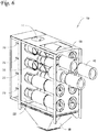
- FIGS. 5 and 6 are, respectively, a cross-sectional view of the filter system of FIG. 1 taken along line 5-5 in FIG. 3 and a partially exploded perspective view of the filter system 10 with some of the walls removed to reveal the spacer elements 30 (in the form of venturi elements as discussed herein) and filter elements 40 located in the dirty air chamber of the filter system 10.
- spacer elements 30 in the form of venturi elements as discussed herein
- filter elements 40 located in the dirty air chamber of the filter system 10.
- each spacer element 30 is depicted as being positioned over only one aperture 28, in one or more alternative embodiments, the clean air outlet 34 of each spacer element 30 may be positioned over more than one aperture in the tubesheet 22 (although it may be desirable to match the size and/or shape of the aperture 28 to the size and/or shape of the clean air outlet 34).
- yokes 44 may, in one or more embodiments, be attached to the spacer elements 30 and/or the tubesheet 22.
- the yokes 44 may be provided to assist in supporting the filter elements 40 within the housing of the filter system 10.
- the use of yokes and/or other structures for supporting filter elements in a filter system may be described in, e.g., U.S. Pat. No. 3,942,962 (Duyckinck ), U.S. Pat. No. 4,218,227 (Frey ), U.S. Pat. No. 5,562,746 (Raether ), U.S. Pat. No. 6,090,173 (Johnson et al. ), U.S. Pat. No. 6,902,592 (Green et al. ), and U.S. Pat. No. 7,641,708 (Kosmider et al. ).
- the filter elements 40 depicted in FIGS. 4-6 are in the form of two-part cartridges, the filter systems described herein can be adapted to use a variety of filter elements provided the filter elements can be used in conjunction with spacer elements as described herein.
- the filter elements may take the form of, e.g., bags, socks, cartridges, etc.
- the blowpipes 20 depicted in connection with the illustrative embodiment of filter system 10 are configured to direct air into the spacer elements 30 through the apertures 28 in the tubesheet 22.
- the air from each of the blowpipes 20 enters the clean air outlet 34 of a corresponding spacer element 30 and exits into the filter element 40 through the clean air inlet 32 to remove particulate matter from the filter elements 40 in a manner similar to that described in, e.g., U.S. Pat. No. 4,218,227 (Frey ), U.S. Pat. No. 5,562,746 (Raether ), U.S. Pat. No. 6,090,173 (Johnson et al. ), U.S. Pat. No. 6,902,592 (Green et al. ), U.S. Pat. No. 7,641,708 (Kosmider et al. ), and U.S. Pat. No. 8,075,648 (Raether ).
- the blowpipes 20 may be provided as part of a pulse-jet cleaning system including one or more sources of pressurized gas (e.g., air), valves and a control system.
- pressurized gas e.g., air
- Illustrative embodiments of potentially suitable pulse-jet cleaning systems may be found in, e.g., U.S. Pat. No. 4,218,227 (Frey ), U.S. Pat. No. 5,562,746 (Raether ), U.S. Pat. No. 6,090,173 (Johnson et al. ), U.S. Pat. No. 6,902,592 (Green et al. ), U.S. Pat. No. 7,641,708 (Kosmider et al. ), and U.S. Pat. No.
- the blowpipes used may include the diverging nozzles and other components and methods described in US Provisional Patent Application No. 61/772,198 titled DIVERGING NOZZLES AND FILTER ELEMENT CLEANING SYSTEMS USING DIVERGING NOZZLES, filed on March 4, 2013.
Landscapes
- Chemical & Material Sciences (AREA)
- Chemical Kinetics & Catalysis (AREA)
- Physics & Mathematics (AREA)
- Geometry (AREA)
- Filtering Of Dispersed Particles In Gases (AREA)
Claims (9)
- Système de filtre comprenant :un boîtier comprenant une plaque tubulaire (22) séparant le boîtier en une chambre d'air souillé (26) et une chambre d'air pur (24) ;une pluralité d'éléments espaceurs (30) attachée à la plaque tubulaire (22), dans lequel chaque élément espaceur de la pluralité d'éléments espaceurs (30) comprend un orifice d'entrée d'air pur (32) et un orifice de sortie d'air pur (34), et dans lequel l'orifice d'entrée d'air pur (32) de chaque élément espaceur de la pluralité d'éléments espaceurs (30) est situé dans la chambre d'air souillé (26) ;une pluralité d'ouvertures (28) dans la plaque tubulaire (22), dans lequel chaque élément espaceur de la pluralité d'éléments espaceurs (30) est positionné sur une ouverture de la pluralité d'ouvertures dans la plaque tubulaire (22) de sorte que de l'air passant de la chambre d'air souillé (26) dans la chambre d'air pur (24) à travers chaque élément espaceur de la pluralité d'éléments espaceurs (30) passe à travers l'ouverture ;une pluralité d'éléments de filtre (40), dans lequel chaque élément de filtre de la pluralité d'éléments de filtre (40) est attaché à l'orifice d'entrée d'air pur (32) d'un élément espaceur de la pluralité d'éléments espaceurs (30) ; etun orifice d'entrée d'air souillé (11 ; 111) attaché au boîtier, dans lequel l'orifice d'entrée d'air souillé (11 ; 111) est configuré pour distribuer un flux d'air souillé dans la chambre d'air souillé,dans lequel l'orifice d'entrée d'air souillé (11 ; 111) est configuré pour distribuer le flux d'air souillé dans la chambre d'air souillé (26) le long d'un axe d'écoulement d'air souillé, et dans lequel l'axe d'écoulement d'air souillé s'étend à travers ou passe au moins un élément espaceur de la pluralité d'éléments espaceurs (30) en un emplacement entre l'orifice d'entrée d'air pur (32) et l'orifice de sortie d'air pur (34) de l'au moins un élément espaceur de sorte que de l'air souillé entrant dans la chambre d'air souillé (26) le long de l'axe d'écoulement d'air souillé entre en contact avec ou passe au moins un élément espaceur de la pluralité d'éléments espaceurs (30) en un emplacement entre l'orifice d'entrée d'air pur (32) et l'orifice de sortie d'air pur (34) de l'au moins un élément espaceur avant d'entrer en contact avec la pluralité d'éléments de filtre (40),
etune trémie (18), en dessous de la chambre d'air souillé, configurée pour recueillir de la matière particulaire se séparant du flux d'air souillé,caractérisé en ce que le boîtier comprend :un panneau de paroi d'extrémité (19) situé à travers la chambre d'air souillé (26) depuis la plaque tubulaire (22), dans lequel chaque élément espaceur de la pluralité d'éléments espaceurs (30) et l'élément de filtre attaché à chaque élément espaceur s'étendent à travers la chambre d'air souillé (26) depuis la plaque tubulaire (22) jusqu'au panneau de paroi d'extrémité (19), etun panneau de paroi supérieur (16) auquel l'orifice d'entrée d'air souillé (11 ; 111) est attaché, de sorte que - en utilisation - une partie de la matière particulaire dans le flux d'air souillé soit déposée directement dans la trémie sans jamais atteindre les éléments de filtre (40). - Système selon la revendication 1, dans lequel chaque élément espaceur de la pluralité d'éléments espaceurs (30) comprend une longueur d'élément mesurée le long d'un axe d'élément s'étendant à travers l'orifice d'entrée d'air pur (32) et l'orifice de sortie d'air pur (34) de l'élément espaceur, et dans lequel l'orifice d'entrée d'air souillé (11; 111) définit une largeur mesurée parallèle à l'axe d'élément qui est inférieure à 2 fois une longueur d'élément moyenne de la pluralité de longueurs d'élément de la pluralité d'éléments espaceurs (30).
- Système selon la revendication 2, dans lequel la largeur de l'orifice d'entrée d'air souillé (111) mesurée parallèle à l'axe d'élément est inférieure ou égale à la longueur d'élément moyenne de la pluralité de longueurs d'élément de la pluralité d'éléments espaceurs (30).
- Système selon l'une quelconque des revendications 1 à 3, dans lequel l'orifice d'entrée d'air souillé (11 ; 111) comprend un périmètre où l'orifice d'entrée d'air souillé (11 ; 111) entre dans la chambre d'air souillé, et en outre dans lequel une saillie du périmètre parallèle à l'axe d'écoulement d'air souillé à travers la chambre d'air souillé (26) ne coupe pas un quelconque élément de filtre (40) de la pluralité d'éléments de filtre (40).
- Système selon l'une quelconque des revendications 1 à 4, dans lequel la plaque tubulaire (22) comprend un côté air souillé orienté vers la chambre d'air souillé (26) et un côté air pur orienté vers la chambre d'air pur (24), et dans lequel l'orifice de sortie d'air pur (34) de chaque élément espaceur de la pluralité d'éléments espaceurs (30) est positionné sur le côté air souillé de la plaque tubulaire (22), et facultativement dans lequel chaque élément espaceur de la pluralité d'éléments espaceurs (30) ne s'étend pas dans la chambre d'air pur (24).
- Système selon l'une quelconque des revendications 1 à 5, dans lequel la pluralité d'éléments espaceurs (30) comprend une pluralité d'éléments venturi, dans lequel chaque élément venturi de la pluralité d'éléments venturi comprend une gorge située entre un orifice d'entrée d'air pur (32) et un orifice de sortie d'air pur (34), et dans lequel l'orifice d'entrée d'air pur (32) de chaque élément venturi de la pluralité d'éléments venturi est situé dans la chambre d'air souillé (26), et dans lequel la gorge de chaque élément venturi de la pluralité d'éléments venturi est positionnée sur le côté air souillé de la plaque tubulaire (22) et est exposée au sein de la chambre d'air souillé (26).
- Système selon l'une quelconque des revendications 1 à 6, dans lequel le système comprend en outre un système de nettoyage par air pulsé comprenant un tuyau de soufflage orienté pour diriger de l'air pulsé dans l'orifice de sortie d'air pur (34) et vers l'orifice d'entrée d'air pur (32) de chaque élément espaceur de la pluralité d'éléments espaceurs (30).
- Procédé d'élimination de matière particulaire dans de l'air souillé à l'aide du système de l'une quelconque des revendications précédentes, le procédé comprenant : la distribution d'air souillé dans une chambre d'air souillé (26) d'un boîtier comprenant une plaque tubulaire (22) séparant le boîtier en la chambre d'air souillé (26) et une chambre d'air pur (24), dans lequel l'air souillé est distribué dans la chambre d'air souillé (26) en un flux d'air souillé le long d'un axe d'écoulement d'air souillé ; et
le positionnement d'une pluralité d'éléments espaceurs (30) et d'éléments de filtre attachés (40) dans la chambre d'air souillé (36), dans lequel chaque élément espaceur de la pluralité d'éléments espaceurs (30) comprend un orifice d'entrée d'air pur (32) et un orifice de sortie d'air pur (34), et dans lequel l'orifice d'entrée d'air pur (32) de chaque élément espaceur de la pluralité d'éléments espaceurs (30) est situé dans la chambre d'air souillé, et en outre dans lequel chaque élément espaceur de la pluralité d'éléments espaceurs (30) et l'élément de filtre attaché à chaque élément espaceur s'étendent à travers la chambre d'air souillé (26) depuis une plaque tubulaire (22) jusqu'à un panneau de paroi d'extrémité (19) situé à travers la chambre d'air souillé (26) depuis la plaque tubulaire (22),
dans lequel les éléments espaceurs (30) et l'orifice d'entrée d'air souillé (11 ; 111) sont agencés de sorte que le flux d'air souillé entrant dans la chambre d'air souillé (26) le long de l'axe d'écoulement d'air souillé entre en contact avec ou passe les surfaces extérieures des éléments espaceurs (30) et de la matière particulaire entraînée dans le flux d'air souillé passe par les éléments espaceurs (30) et aille directement jusqu'à la trémie en dessous de la chambre d'air souillé (26) sans jamais atteindre les éléments de filtre (40). - Procédé selon la revendication 8, dans lequel l'air souillé circulant dans la chambre d'air souillé (26) à travers l'orifice d'entrée d'air souillé (11 ; 111) le long de l'axe d'écoulement d'air souillé entre en contact avec au moins un élément espaceur de la pluralité d'éléments espaceurs (30) ou passe un ou plusieurs éléments espaceurs (30) de la pluralité d'éléments espaceurs (30) en un emplacement entre l'orifice d'entrée d'air pur (32) et l'orifice de sortie d'air pur (34) de chacun des éléments espaceurs (30) avant d'entrer en contact avec la pluralité d'éléments de filtre (40).
Priority Applications (2)
| Application Number | Priority Date | Filing Date | Title |
|---|---|---|---|
| EP18163720.8A EP3381537B1 (fr) | 2012-05-17 | 2013-05-17 | Systèmes de filtres dotés d'éléments espaceurs de chambre à air chargé de poussières et leurs procédés d'utilisation |
| EP20182484.4A EP3733260B1 (fr) | 2012-05-17 | 2013-05-17 | Systèmes de filtres dotés d'éléments espaceurs de chambre à air chargé de poussières et leurs procédés d'utilisation |
Applications Claiming Priority (3)
| Application Number | Priority Date | Filing Date | Title |
|---|---|---|---|
| US201261648494P | 2012-05-17 | 2012-05-17 | |
| US201361790184P | 2013-03-15 | 2013-03-15 | |
| PCT/US2013/041540 WO2013173691A1 (fr) | 2012-05-17 | 2013-05-17 | Systèmes de filtres dotés d'éléments espaceurs de chambre à air chargé de poussières et procédés pour les utiliser |
Related Child Applications (2)
| Application Number | Title | Priority Date | Filing Date |
|---|---|---|---|
| EP20182484.4A Division EP3733260B1 (fr) | 2012-05-17 | 2013-05-17 | Systèmes de filtres dotés d'éléments espaceurs de chambre à air chargé de poussières et leurs procédés d'utilisation |
| EP18163720.8A Division EP3381537B1 (fr) | 2012-05-17 | 2013-05-17 | Systèmes de filtres dotés d'éléments espaceurs de chambre à air chargé de poussières et leurs procédés d'utilisation |
Publications (2)
| Publication Number | Publication Date |
|---|---|
| EP2849866A1 EP2849866A1 (fr) | 2015-03-25 |
| EP2849866B1 true EP2849866B1 (fr) | 2018-04-04 |
Family
ID=48538070
Family Applications (3)
| Application Number | Title | Priority Date | Filing Date |
|---|---|---|---|
| EP13726072.5A Active EP2849866B1 (fr) | 2012-05-17 | 2013-05-17 | Systèmes de filtres dotés d'éléments espaceurs de chambre à air chargé de poussières et procédés pour les utiliser |
| EP18163720.8A Active EP3381537B1 (fr) | 2012-05-17 | 2013-05-17 | Systèmes de filtres dotés d'éléments espaceurs de chambre à air chargé de poussières et leurs procédés d'utilisation |
| EP20182484.4A Active EP3733260B1 (fr) | 2012-05-17 | 2013-05-17 | Systèmes de filtres dotés d'éléments espaceurs de chambre à air chargé de poussières et leurs procédés d'utilisation |
Family Applications After (2)
| Application Number | Title | Priority Date | Filing Date |
|---|---|---|---|
| EP18163720.8A Active EP3381537B1 (fr) | 2012-05-17 | 2013-05-17 | Systèmes de filtres dotés d'éléments espaceurs de chambre à air chargé de poussières et leurs procédés d'utilisation |
| EP20182484.4A Active EP3733260B1 (fr) | 2012-05-17 | 2013-05-17 | Systèmes de filtres dotés d'éléments espaceurs de chambre à air chargé de poussières et leurs procédés d'utilisation |
Country Status (7)
| Country | Link |
|---|---|
| US (7) | US9067164B2 (fr) |
| EP (3) | EP2849866B1 (fr) |
| CN (2) | CN104302379A (fr) |
| BR (1) | BR112014028595B1 (fr) |
| IN (1) | IN2014DN09648A (fr) |
| MX (1) | MX349691B (fr) |
| WO (1) | WO2013173691A1 (fr) |
Families Citing this family (10)
| Publication number | Priority date | Publication date | Assignee | Title |
|---|---|---|---|---|
| EP2849866B1 (fr) | 2012-05-17 | 2018-04-04 | Donaldson Company, Inc. | Systèmes de filtres dotés d'éléments espaceurs de chambre à air chargé de poussières et procédés pour les utiliser |
| HUE055672T2 (hu) | 2013-03-04 | 2021-12-28 | Donaldson Co Inc | Levegõszûrõ rendszerek, valamint eljárások ezek alkalmazására |
| HUE054798T2 (hu) | 2013-03-15 | 2021-09-28 | Donaldson Co Inc | Tojásdad, csõ alakú szûrõbetétek és ezeket alkalmazó szûrõrendszerek |
| US10295220B1 (en) | 2014-11-13 | 2019-05-21 | Acme Manufacturing Corporation | Snow removal assembly, apparatus and method for air handling units |
| CN106422855A (zh) * | 2016-11-10 | 2017-02-22 | 佛山市利德嘉陶瓷制釉有限公司 | 螺旋混合机进料口加料除尘设备 |
| RU2765174C2 (ru) * | 2017-05-02 | 2022-01-26 | Джой Глобал Серфейс Майнинг Инк | Фильтрация воздуха для самоходной горной машины |
| MX2020009218A (es) * | 2018-03-07 | 2020-10-14 | Products Unlimited Inc | Placa de entrada que define un orificio para dispositivo de filtracion. |
| US12201931B2 (en) | 2018-03-07 | 2025-01-21 | Products Unlimited, Inc. | Orifice-defining entry plate with support brace for filtration device |
| GB2592267A (en) * | 2020-02-24 | 2021-08-25 | Altair Uk Ltd | Pulse nozzle for filter cleaning systems |
| US11339750B2 (en) | 2020-04-29 | 2022-05-24 | Deere & Company | Combustion air filtration apparatus |
Family Cites Families (35)
| Publication number | Priority date | Publication date | Assignee | Title |
|---|---|---|---|---|
| FR1507976A (fr) * | 1967-02-08 | 1967-12-29 | Hydromation Engineering Compan | Collecteur de poussières |
| US3963467A (en) * | 1973-03-08 | 1976-06-15 | Rolschau David W | Dust filter apparatus |
| US3942962A (en) | 1974-05-08 | 1976-03-09 | U.S. Filter Company | Pulse jet and venturi liner |
| US4073632A (en) | 1975-07-07 | 1978-02-14 | United States Filter Corporation | Filter bag assembly |
| US4218227A (en) | 1975-07-28 | 1980-08-19 | Donaldson Company, Inc. | Dust collector |
| US4159197A (en) | 1977-10-05 | 1979-06-26 | Donaldson Company, Inc. | Suspension gasket seal and system for baghouse filter units |
| US4276069A (en) * | 1979-09-12 | 1981-06-30 | American Air Filter Company, Inc. | Filter arrangement |
| US4504293A (en) * | 1980-11-06 | 1985-03-12 | Donaldson Company, Inc. | Self-cleaning air filter |
| US4395269B1 (en) | 1981-09-30 | 1994-08-30 | Donaldson Co Inc | Compact dust filter assembly |
| US4445915A (en) | 1982-08-16 | 1984-05-01 | Flex-Kleen Corporation | Dust collector filter cartridge and attachment means for suspending same from baghouse tube sheet |
| US4436536A (en) | 1982-09-29 | 1984-03-13 | Flex-Kleen Corporation | Dust collecting filter cartridge and attachment structure for suspending same from baghouse tube sheet |
| US4443237A (en) | 1982-11-22 | 1984-04-17 | Flex-Kleen Corporation | Dust collecting filter cartridge and attachment structure for suspending same from baghouse tube sheet |
| US4424070A (en) | 1982-11-22 | 1984-01-03 | Flex-Kleen Corporation | Dust collecting filter cartridge and attachment structure for suspending same from baghouse tube sheet |
| US4652285A (en) | 1983-10-19 | 1987-03-24 | Greene John P | Gas filter apparatus |
| US4661131A (en) | 1983-11-07 | 1987-04-28 | Howeth David Franklin | Backflushed air filters |
| US4880530A (en) | 1987-12-07 | 1989-11-14 | Frey Robert E | Self-cleaning screening device |
| DK65889A (da) | 1988-04-02 | 1989-10-03 | Mueller S F & Partner | Filteranlaeg |
| US5211846A (en) | 1990-07-30 | 1993-05-18 | Pleatco Electronic & Filter Corp. | Replacement filter cartridge assembly |
| US5222488A (en) | 1991-07-11 | 1993-06-29 | Donaldson Company, Inc. | Respirator air filter cartridge with a replaceable filter element |
| US5207812B1 (en) | 1992-05-08 | 1996-10-01 | Gore & Ass | Filter cartridge |
| DE9311201U1 (de) | 1993-07-27 | 1993-10-21 | IWA-Ingenieurbüro Wolfgang Adamski GmbH, 53773 Hennef | Venturidüse |
| AU686191B2 (en) * | 1993-09-20 | 1998-02-05 | Terex Mining Australia Pty Limited | Improvements in dust collection efficiency |
| CA2187674A1 (fr) | 1994-04-11 | 1995-10-19 | Thomas D. Raether | Ensemble filtre a air destine a filtrer de l'air charge de matieres particulaires |
| US5730766A (en) | 1996-11-05 | 1998-03-24 | Bha Group, Inc. | Non-round unitary filter cartridge |
| US5803939A (en) * | 1997-04-24 | 1998-09-08 | Alanco Environmental Resources Corp. | Industrial dust collector and method for its use |
| US6090173A (en) | 1998-08-07 | 2000-07-18 | Donaldson Company, Inc. | Air filter assembly for filtering air with particulate matter |
| US7264656B2 (en) | 2000-06-30 | 2007-09-04 | Donaldson Company, Inc. | Air filter assembly having non-cylindrical filter elements, for filtering air with particulate matter |
| US6791215B2 (en) * | 2002-06-05 | 2004-09-14 | Board Of Regents The University Of Texas System | Fault tolerant linear actuator |
| US6902592B2 (en) * | 2002-10-25 | 2005-06-07 | United Air Specialists, Inc. | Apparatus and method for cleaning an air filter unit |
| JP2006095004A (ja) | 2004-09-29 | 2006-04-13 | Nittan Co Ltd | 消火剤混合装置 |
| DE202006005677U1 (de) | 2006-04-05 | 2006-07-20 | Kethers, Ulrich | Vorrichtung zum Reinigen von Rohgas |
| CN101616724A (zh) | 2006-11-30 | 2009-12-30 | 唐纳森公司 | 清洁过滤元件的喷嘴结构和方法 |
| US7918907B2 (en) | 2008-02-29 | 2011-04-05 | Venturedyne, Ltd. | Cleaning nozzle for dust collector |
| US20120324845A1 (en) * | 2011-06-27 | 2012-12-27 | James Roy Doehla | Filter assembly for use in a baghouse |
| EP2849866B1 (fr) | 2012-05-17 | 2018-04-04 | Donaldson Company, Inc. | Systèmes de filtres dotés d'éléments espaceurs de chambre à air chargé de poussières et procédés pour les utiliser |
-
2013
- 2013-05-17 EP EP13726072.5A patent/EP2849866B1/fr active Active
- 2013-05-17 EP EP18163720.8A patent/EP3381537B1/fr active Active
- 2013-05-17 CN CN201380025275.4A patent/CN104302379A/zh active Pending
- 2013-05-17 US US13/896,564 patent/US9067164B2/en active Active
- 2013-05-17 EP EP20182484.4A patent/EP3733260B1/fr active Active
- 2013-05-17 WO PCT/US2013/041540 patent/WO2013173691A1/fr not_active Ceased
- 2013-05-17 CN CN201910504231.9A patent/CN110237605A/zh active Pending
- 2013-05-17 BR BR112014028595-0A patent/BR112014028595B1/pt active IP Right Grant
- 2013-05-17 MX MX2014013944A patent/MX349691B/es active IP Right Grant
-
2014
- 2014-11-15 IN IN9648DEN2014 patent/IN2014DN09648A/en unknown
-
2015
- 2015-06-29 US US14/753,592 patent/US9795908B2/en active Active
-
2017
- 2017-10-04 US US15/724,441 patent/US10556198B2/en active Active
-
2019
- 2019-12-20 US US16/722,259 patent/US11123671B2/en active Active
-
2021
- 2021-08-26 US US17/412,685 patent/US11745133B2/en active Active
-
2023
- 2023-07-31 US US18/228,318 patent/US12134060B2/en active Active
-
2024
- 2024-10-18 US US18/920,193 patent/US20250041781A1/en active Pending
Also Published As
| Publication number | Publication date |
|---|---|
| BR112014028595A2 (pt) | 2018-04-24 |
| US20180021712A1 (en) | 2018-01-25 |
| CN104302379A (zh) | 2015-01-21 |
| WO2013173691A1 (fr) | 2013-11-21 |
| US9795908B2 (en) | 2017-10-24 |
| EP3733260B1 (fr) | 2022-01-05 |
| MX2014013944A (es) | 2015-02-17 |
| BR112014028595B1 (pt) | 2020-12-29 |
| IN2014DN09648A (fr) | 2015-07-31 |
| US12134060B2 (en) | 2024-11-05 |
| MX349691B (es) | 2017-08-09 |
| US11123671B2 (en) | 2021-09-21 |
| US20250041781A1 (en) | 2025-02-06 |
| US20150298038A1 (en) | 2015-10-22 |
| EP3381537B1 (fr) | 2020-08-05 |
| US20200122073A1 (en) | 2020-04-23 |
| US20210402337A1 (en) | 2021-12-30 |
| US10556198B2 (en) | 2020-02-11 |
| US20130305926A1 (en) | 2013-11-21 |
| EP3733260A1 (fr) | 2020-11-04 |
| US11745133B2 (en) | 2023-09-05 |
| CN110237605A (zh) | 2019-09-17 |
| US20230372857A1 (en) | 2023-11-23 |
| EP3381537A1 (fr) | 2018-10-03 |
| EP2849866A1 (fr) | 2015-03-25 |
| US9067164B2 (en) | 2015-06-30 |
Similar Documents
| Publication | Publication Date | Title |
|---|---|---|
| US12134060B2 (en) | Filter systems with dirty air chamber spacer elements and methods of using the same | |
| US12090435B2 (en) | Ovate tubular filter cartridges and filter systems using the same | |
| CN113769498B (zh) | 空气过滤器系统及其使用方法 | |
| CA2066970C (fr) | Depoussiereur a parois prevenant le re-entrainement des particules | |
| EP2849867B1 (fr) | Ensemble filtre à air comportant des éléments venturi à sorties d'impulsions prolongées | |
| US20140238240A1 (en) | Downflow dust collectors having dirty air channels | |
| US20110030558A1 (en) | Dust collector, filtration arrangment, and methods |
Legal Events
| Date | Code | Title | Description |
|---|---|---|---|
| PUAI | Public reference made under article 153(3) epc to a published international application that has entered the european phase |
Free format text: ORIGINAL CODE: 0009012 |
|
| 17P | Request for examination filed |
Effective date: 20141204 |
|
| AK | Designated contracting states |
Kind code of ref document: A1 Designated state(s): AL AT BE BG CH CY CZ DE DK EE ES FI FR GB GR HR HU IE IS IT LI LT LU LV MC MK MT NL NO PL PT RO RS SE SI SK SM TR |
|
| AX | Request for extension of the european patent |
Extension state: BA ME |
|
| DAX | Request for extension of the european patent (deleted) | ||
| 17Q | First examination report despatched |
Effective date: 20160726 |
|
| STAA | Information on the status of an ep patent application or granted ep patent |
Free format text: STATUS: EXAMINATION IS IN PROGRESS |
|
| GRAP | Despatch of communication of intention to grant a patent |
Free format text: ORIGINAL CODE: EPIDOSNIGR1 |
|
| STAA | Information on the status of an ep patent application or granted ep patent |
Free format text: STATUS: GRANT OF PATENT IS INTENDED |
|
| INTG | Intention to grant announced |
Effective date: 20171103 |
|
| GRAS | Grant fee paid |
Free format text: ORIGINAL CODE: EPIDOSNIGR3 |
|
| GRAA | (expected) grant |
Free format text: ORIGINAL CODE: 0009210 |
|
| STAA | Information on the status of an ep patent application or granted ep patent |
Free format text: STATUS: THE PATENT HAS BEEN GRANTED |
|
| AK | Designated contracting states |
Kind code of ref document: B1 Designated state(s): AL AT BE BG CH CY CZ DE DK EE ES FI FR GB GR HR HU IE IS IT LI LT LU LV MC MK MT NL NO PL PT RO RS SE SI SK SM TR |
|
| REG | Reference to a national code |
Ref country code: GB Ref legal event code: FG4D |
|
| REG | Reference to a national code |
Ref country code: CH Ref legal event code: EP |
|
| REG | Reference to a national code |
Ref country code: AT Ref legal event code: REF Ref document number: 984981 Country of ref document: AT Kind code of ref document: T Effective date: 20180415 |
|
| REG | Reference to a national code |
Ref country code: DE Ref legal event code: R096 Ref document number: 602013035364 Country of ref document: DE |
|
| REG | Reference to a national code |
Ref country code: IE Ref legal event code: FG4D |
|
| REG | Reference to a national code |
Ref country code: FR Ref legal event code: PLFP Year of fee payment: 6 |
|
| REG | Reference to a national code |
Ref country code: NL Ref legal event code: MP Effective date: 20180404 |
|
| REG | Reference to a national code |
Ref country code: LT Ref legal event code: MG4D |
|
| PG25 | Lapsed in a contracting state [announced via postgrant information from national office to epo] |
Ref country code: NL Free format text: LAPSE BECAUSE OF FAILURE TO SUBMIT A TRANSLATION OF THE DESCRIPTION OR TO PAY THE FEE WITHIN THE PRESCRIBED TIME-LIMIT Effective date: 20180404 |
|
| PG25 | Lapsed in a contracting state [announced via postgrant information from national office to epo] |
Ref country code: FI Free format text: LAPSE BECAUSE OF FAILURE TO SUBMIT A TRANSLATION OF THE DESCRIPTION OR TO PAY THE FEE WITHIN THE PRESCRIBED TIME-LIMIT Effective date: 20180404 Ref country code: NO Free format text: LAPSE BECAUSE OF FAILURE TO SUBMIT A TRANSLATION OF THE DESCRIPTION OR TO PAY THE FEE WITHIN THE PRESCRIBED TIME-LIMIT Effective date: 20180704 Ref country code: AL Free format text: LAPSE BECAUSE OF FAILURE TO SUBMIT A TRANSLATION OF THE DESCRIPTION OR TO PAY THE FEE WITHIN THE PRESCRIBED TIME-LIMIT Effective date: 20180404 Ref country code: SE Free format text: LAPSE BECAUSE OF FAILURE TO SUBMIT A TRANSLATION OF THE DESCRIPTION OR TO PAY THE FEE WITHIN THE PRESCRIBED TIME-LIMIT Effective date: 20180404 Ref country code: PL Free format text: LAPSE BECAUSE OF FAILURE TO SUBMIT A TRANSLATION OF THE DESCRIPTION OR TO PAY THE FEE WITHIN THE PRESCRIBED TIME-LIMIT Effective date: 20180404 Ref country code: LT Free format text: LAPSE BECAUSE OF FAILURE TO SUBMIT A TRANSLATION OF THE DESCRIPTION OR TO PAY THE FEE WITHIN THE PRESCRIBED TIME-LIMIT Effective date: 20180404 Ref country code: ES Free format text: LAPSE BECAUSE OF FAILURE TO SUBMIT A TRANSLATION OF THE DESCRIPTION OR TO PAY THE FEE WITHIN THE PRESCRIBED TIME-LIMIT Effective date: 20180404 Ref country code: BG Free format text: LAPSE BECAUSE OF FAILURE TO SUBMIT A TRANSLATION OF THE DESCRIPTION OR TO PAY THE FEE WITHIN THE PRESCRIBED TIME-LIMIT Effective date: 20180704 |
|
| PG25 | Lapsed in a contracting state [announced via postgrant information from national office to epo] |
Ref country code: HR Free format text: LAPSE BECAUSE OF FAILURE TO SUBMIT A TRANSLATION OF THE DESCRIPTION OR TO PAY THE FEE WITHIN THE PRESCRIBED TIME-LIMIT Effective date: 20180404 Ref country code: RS Free format text: LAPSE BECAUSE OF FAILURE TO SUBMIT A TRANSLATION OF THE DESCRIPTION OR TO PAY THE FEE WITHIN THE PRESCRIBED TIME-LIMIT Effective date: 20180404 Ref country code: GR Free format text: LAPSE BECAUSE OF FAILURE TO SUBMIT A TRANSLATION OF THE DESCRIPTION OR TO PAY THE FEE WITHIN THE PRESCRIBED TIME-LIMIT Effective date: 20180705 Ref country code: LV Free format text: LAPSE BECAUSE OF FAILURE TO SUBMIT A TRANSLATION OF THE DESCRIPTION OR TO PAY THE FEE WITHIN THE PRESCRIBED TIME-LIMIT Effective date: 20180404 |
|
| REG | Reference to a national code |
Ref country code: CH Ref legal event code: PL |
|
| REG | Reference to a national code |
Ref country code: AT Ref legal event code: MK05 Ref document number: 984981 Country of ref document: AT Kind code of ref document: T Effective date: 20180404 |
|
| PG25 | Lapsed in a contracting state [announced via postgrant information from national office to epo] |
Ref country code: PT Free format text: LAPSE BECAUSE OF FAILURE TO SUBMIT A TRANSLATION OF THE DESCRIPTION OR TO PAY THE FEE WITHIN THE PRESCRIBED TIME-LIMIT Effective date: 20180806 |
|
| REG | Reference to a national code |
Ref country code: DE Ref legal event code: R097 Ref document number: 602013035364 Country of ref document: DE |
|
| REG | Reference to a national code |
Ref country code: BE Ref legal event code: MM Effective date: 20180531 |
|
| PG25 | Lapsed in a contracting state [announced via postgrant information from national office to epo] |
Ref country code: CZ Free format text: LAPSE BECAUSE OF FAILURE TO SUBMIT A TRANSLATION OF THE DESCRIPTION OR TO PAY THE FEE WITHIN THE PRESCRIBED TIME-LIMIT Effective date: 20180404 Ref country code: RO Free format text: LAPSE BECAUSE OF FAILURE TO SUBMIT A TRANSLATION OF THE DESCRIPTION OR TO PAY THE FEE WITHIN THE PRESCRIBED TIME-LIMIT Effective date: 20180404 Ref country code: SK Free format text: LAPSE BECAUSE OF FAILURE TO SUBMIT A TRANSLATION OF THE DESCRIPTION OR TO PAY THE FEE WITHIN THE PRESCRIBED TIME-LIMIT Effective date: 20180404 Ref country code: EE Free format text: LAPSE BECAUSE OF FAILURE TO SUBMIT A TRANSLATION OF THE DESCRIPTION OR TO PAY THE FEE WITHIN THE PRESCRIBED TIME-LIMIT Effective date: 20180404 Ref country code: AT Free format text: LAPSE BECAUSE OF FAILURE TO SUBMIT A TRANSLATION OF THE DESCRIPTION OR TO PAY THE FEE WITHIN THE PRESCRIBED TIME-LIMIT Effective date: 20180404 Ref country code: DK Free format text: LAPSE BECAUSE OF FAILURE TO SUBMIT A TRANSLATION OF THE DESCRIPTION OR TO PAY THE FEE WITHIN THE PRESCRIBED TIME-LIMIT Effective date: 20180404 Ref country code: MC Free format text: LAPSE BECAUSE OF FAILURE TO SUBMIT A TRANSLATION OF THE DESCRIPTION OR TO PAY THE FEE WITHIN THE PRESCRIBED TIME-LIMIT Effective date: 20180404 |
|
| PLBE | No opposition filed within time limit |
Free format text: ORIGINAL CODE: 0009261 |
|
| STAA | Information on the status of an ep patent application or granted ep patent |
Free format text: STATUS: NO OPPOSITION FILED WITHIN TIME LIMIT |
|
| REG | Reference to a national code |
Ref country code: IE Ref legal event code: MM4A |
|
| PG25 | Lapsed in a contracting state [announced via postgrant information from national office to epo] |
Ref country code: CH Free format text: LAPSE BECAUSE OF NON-PAYMENT OF DUE FEES Effective date: 20180531 Ref country code: SM Free format text: LAPSE BECAUSE OF FAILURE TO SUBMIT A TRANSLATION OF THE DESCRIPTION OR TO PAY THE FEE WITHIN THE PRESCRIBED TIME-LIMIT Effective date: 20180404 Ref country code: IT Free format text: LAPSE BECAUSE OF FAILURE TO SUBMIT A TRANSLATION OF THE DESCRIPTION OR TO PAY THE FEE WITHIN THE PRESCRIBED TIME-LIMIT Effective date: 20180404 Ref country code: LI Free format text: LAPSE BECAUSE OF NON-PAYMENT OF DUE FEES Effective date: 20180531 |
|
| 26N | No opposition filed |
Effective date: 20190107 |
|
| PG25 | Lapsed in a contracting state [announced via postgrant information from national office to epo] |
Ref country code: LU Free format text: LAPSE BECAUSE OF NON-PAYMENT OF DUE FEES Effective date: 20180517 |
|
| PG25 | Lapsed in a contracting state [announced via postgrant information from national office to epo] |
Ref country code: IE Free format text: LAPSE BECAUSE OF NON-PAYMENT OF DUE FEES Effective date: 20180517 |
|
| PG25 | Lapsed in a contracting state [announced via postgrant information from national office to epo] |
Ref country code: SI Free format text: LAPSE BECAUSE OF FAILURE TO SUBMIT A TRANSLATION OF THE DESCRIPTION OR TO PAY THE FEE WITHIN THE PRESCRIBED TIME-LIMIT Effective date: 20180404 Ref country code: BE Free format text: LAPSE BECAUSE OF NON-PAYMENT OF DUE FEES Effective date: 20180531 |
|
| PG25 | Lapsed in a contracting state [announced via postgrant information from national office to epo] |
Ref country code: MT Free format text: LAPSE BECAUSE OF NON-PAYMENT OF DUE FEES Effective date: 20180517 |
|
| PG25 | Lapsed in a contracting state [announced via postgrant information from national office to epo] |
Ref country code: TR Free format text: LAPSE BECAUSE OF FAILURE TO SUBMIT A TRANSLATION OF THE DESCRIPTION OR TO PAY THE FEE WITHIN THE PRESCRIBED TIME-LIMIT Effective date: 20180404 |
|
| PG25 | Lapsed in a contracting state [announced via postgrant information from national office to epo] |
Ref country code: HU Free format text: LAPSE BECAUSE OF FAILURE TO SUBMIT A TRANSLATION OF THE DESCRIPTION OR TO PAY THE FEE WITHIN THE PRESCRIBED TIME-LIMIT; INVALID AB INITIO Effective date: 20130517 |
|
| PG25 | Lapsed in a contracting state [announced via postgrant information from national office to epo] |
Ref country code: CY Free format text: LAPSE BECAUSE OF FAILURE TO SUBMIT A TRANSLATION OF THE DESCRIPTION OR TO PAY THE FEE WITHIN THE PRESCRIBED TIME-LIMIT Effective date: 20180404 Ref country code: MK Free format text: LAPSE BECAUSE OF NON-PAYMENT OF DUE FEES Effective date: 20180404 |
|
| PG25 | Lapsed in a contracting state [announced via postgrant information from national office to epo] |
Ref country code: IS Free format text: LAPSE BECAUSE OF FAILURE TO SUBMIT A TRANSLATION OF THE DESCRIPTION OR TO PAY THE FEE WITHIN THE PRESCRIBED TIME-LIMIT Effective date: 20180804 |
|
| P01 | Opt-out of the competence of the unified patent court (upc) registered |
Effective date: 20230413 |
|
| PGFP | Annual fee paid to national office [announced via postgrant information from national office to epo] |
Ref country code: DE Payment date: 20250423 Year of fee payment: 13 |
|
| PGFP | Annual fee paid to national office [announced via postgrant information from national office to epo] |
Ref country code: GB Payment date: 20250423 Year of fee payment: 13 |
|
| PGFP | Annual fee paid to national office [announced via postgrant information from national office to epo] |
Ref country code: FR Payment date: 20250423 Year of fee payment: 13 |