EP2849961B1 - Belüftungssteuerungssystem und -verfahren für eine fahrzeugkabine - Google Patents
Belüftungssteuerungssystem und -verfahren für eine fahrzeugkabine Download PDFInfo
- Publication number
- EP2849961B1 EP2849961B1 EP12735623.6A EP12735623A EP2849961B1 EP 2849961 B1 EP2849961 B1 EP 2849961B1 EP 12735623 A EP12735623 A EP 12735623A EP 2849961 B1 EP2849961 B1 EP 2849961B1
- Authority
- EP
- European Patent Office
- Prior art keywords
- air
- sub
- rate
- cabin
- flow
- Prior art date
- Legal status (The legal status is an assumption and is not a legal conclusion. Google has not performed a legal analysis and makes no representation as to the accuracy of the status listed.)
- Active
Links
Images

Classifications
-
- B—PERFORMING OPERATIONS; TRANSPORTING
- B60—VEHICLES IN GENERAL
- B60H—ARRANGEMENTS OF HEATING, COOLING, VENTILATING OR OTHER AIR-TREATING DEVICES SPECIALLY ADAPTED FOR PASSENGER OR GOODS SPACES OF VEHICLES
- B60H1/00—Heating, cooling or ventilating devices
- B60H1/00642—Control systems or circuits; Control members or indication devices for heating, cooling or ventilating devices
- B60H1/0065—Control members, e.g. levers or knobs
-
- B—PERFORMING OPERATIONS; TRANSPORTING
- B60—VEHICLES IN GENERAL
- B60H—ARRANGEMENTS OF HEATING, COOLING, VENTILATING OR OTHER AIR-TREATING DEVICES SPECIALLY ADAPTED FOR PASSENGER OR GOODS SPACES OF VEHICLES
- B60H1/00—Heating, cooling or ventilating devices
- B60H1/00642—Control systems or circuits; Control members or indication devices for heating, cooling or ventilating devices
- B60H1/00814—Control systems or circuits characterised by their output, for controlling particular components of the heating, cooling or ventilating installation
- B60H1/00821—Control systems or circuits characterised by their output, for controlling particular components of the heating, cooling or ventilating installation the components being ventilating, air admitting or air distributing devices
- B60H1/00835—Damper doors, e.g. position control
- B60H1/00842—Damper doors, e.g. position control the system comprising a plurality of damper doors; Air distribution between several outlets
-
- B—PERFORMING OPERATIONS; TRANSPORTING
- B60—VEHICLES IN GENERAL
- B60H—ARRANGEMENTS OF HEATING, COOLING, VENTILATING OR OTHER AIR-TREATING DEVICES SPECIALLY ADAPTED FOR PASSENGER OR GOODS SPACES OF VEHICLES
- B60H1/00—Heating, cooling or ventilating devices
- B60H1/00642—Control systems or circuits; Control members or indication devices for heating, cooling or ventilating devices
- B60H1/00985—Control systems or circuits characterised by display or indicating devices, e.g. voice simulators
Definitions
- the present invention relates to a ventilation control system for a cabin of a vehicle, and a method for controlling the ventilation in a cabin of a vehicle.
- Document DE41 19 475 A1 discloses a ventilation control system for a cabin of a vehicle, comprising first, second and third air ducts, each air circuit being capable of directing an air sub flow at a flow rate and that activation of a dedicated switch enables the user to increase or decrease as desired the amount of air delivered in the associated duct.
- the prior art document also discloses that the fan control and the damper actuator control act such that the amount of air at the middle and lower air outlet groups remains constant.
- Vehicles have been provided with a ventilation control system of their cabin for many years. Typically, an air flow is blown into the cabin; said air flow can be heated when the outside temperature is low, especially in winter, and cooled when the outside temperature is high, especially in summer.
- Such a system generally comprises at least three air circuits which direct an air sub flow towards openings arranged in distinct locations inside the vehicle cabin, for example to blow air towards the windscreen, the head, the torso and/or the feet of the cabin occupant.
- a conventional ventilation control system typically comprises an electronic control unit which is capable of controlling some parameters of the air flow.
- Said parameters can include the air flow temperature, the air flow rate, and the air distribution, i.e. the respective rates of the air sub flows in the air circuits.
- the electronic control unit can be operated in an automatic mode, in which the parameters are automatically controlled in order to reach a preset target temperature in the cabin - in a transient mode - and to maintain said target temperature in the cabin - in a permanent mode.
- the electronic control unit can alternatively be operated in a manual or a semi automatic mode, in which at least one of the parameters is manually set by the user, according to his/her preferences.
- a widespread request among users is to have the opportunity to manually set the air distribution so that it adequately suits his/her needs and wishes.
- some users do not like having air blown towards their face, while others may feel like having air blown both towards their face and their feet even if it may not be a common request.
- an object of the invention is to provide such a ventilation control system which allows the user to more accurately adjust the air distribution, to more precisely personalise it, and/or to more easily set it.
- Another object of the invention is to reliably inform the user of the current air distribution, in particular to enable him/her to even better adjust it.
- the invention relates to a ventilation control system for a cabin of a vehicle according to claim 1.
- the invention makes it possible to simplify the system, especially regarding the structure and the processing. This results in a more robust and less expensive system.
- the distribution input device thereby proves easy to use, both because only one control member is provided for a given air circuit, and because one control member is provided for each of said air circuits rather than a single input device for setting the global air distribution.
- the distribution input device and the electronic control unit are designed so that manual actuations of each dedicated control member cause one-way variations of the sub-flow in the corresponding air circuit.
- one-way variations it is meant that depending on the embodiment of the invention the distribution input device and the electronic control unit are designed so that manual actuations of each dedicated control member can only increase the air sub flow rate in the corresponding air circuit or to the contrary in an alternative embodiment of the invention manual actuations of each dedicated control member can only decrease the air sub flow rate in the corresponding air circuit.
- Such a dedicated control member is a device which is very easy to actuate, especially for a user that keeps driving while setting the parameters of the system.
- setting the air distribution with the ventilation control system according to the invention is easy, quick and intuitive, which is particularly advantageous when the user is driving.
- the distribution input device and the electronic control unit are designed so that a manual actuation of one dedicated control member causes an increase of the rate of the air sub-flow in the corresponding air circuit.
- each dedicated control member is actionable between two states.
- each dedicated control member is a key and a pressure on one dedicated key causes a one-way variation of the rate of the air sub-flow in the corresponding air circuit.
- the term "key” can mean a button that can be pressed by a user, or a zone on a touch screen.
- a pressure on one dedicated key causes an increase of the rate of the air sub-flow in the corresponding air circuit.
- the invention relates to a method for controlling the ventilation in a cabin of a vehicle which is equipped with a ventilation control system according to claim 13.
- a manual actuation of the one dedicated control member causes an increase of the sub flow rate in said corresponding air circuit.
- sub flow rates in other air circuits are automatically adjusted in such a way that the sum of all air sub flow rates remains substantially constant.
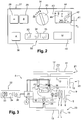
- Figure 1 is schematically and partially shown a cabin 1 of a vehicle, said cabin 1 comprising a windscreen 2 and side windows 3.
- the invention provides a ventilation control system 4 for the cabin 1.
- This system 4 can make it possible to bring and maintain the temperature in the cabin 1 to a target temperature Tt that is preset by the user, i.e. the cabin occupant, who is typically the vehicle driver.
- the ventilation control system 4 comprises a unit 5 which typically includes a fan 6, a heater 7 and a cooler 8.
- the unit 5 is capable of providing a heated or cooled air flow F which will be directed towards the cabin 1.
- the heater 7 can be a radiator
- the cooler 8 can be an evaporator forming part of a refrigerant circuit of an air conditioning system.
- a refrigerant circuit typically carries a refrigerant in a loop through a compressor, a condenser, an expander and an evaporator capable of cooling an air flow directed towards the cabin.
- the ventilation control system 4 also comprises air circuits connected to the unit 5 and designed to carry some of the air flow towards various locations in the cabin 1 and to blow it inside the cabin. More precisely, in the embodiment shown in Figure 1 , the system 4 comprises a first, a second and a third air circuits 11, 12, 13. However, according to the invention, the number of circuits is not limited to three.
- Each air circuit 11, 12, 13 may be connected to at least one dedicated outlet 14, 15, 16 provided on the unit 5 and is capable of directing an air sub flow F1, F2, F3 towards the cabin 1 through at least one opening 17, 18, 19.
- Each air sub flow forms at least part of the air flow.
- the rate Q1, Q2, Q3 of each sub flow F1, F2, F3 can range between 0% and 100% of the rate Q of the air flow F.
- the openings 17, 18, 19 of the first, second and third air circuits 11, 12, 13 are located respectively in a distinct first, second and third distribution areas 21, 22, 23 in the cabin 1.
- the first distribution area 21, in which are located the first openings 17 of the first air circuit 11, can include the windscreen 2 and/or the area near the head of the cabin occupant.
- the first distribution area 21 can be situated in the upper part of the cabin 1.
- the second distribution area 22, in which are located the second openings 18 of the second air circuit 12, can include the area of the torso of the cabin occupant and/or the front part of the side windows 3. In other words, the second distribution area 22 can be situated in the middle part of the cabin 1.
- the third distribution area 23 in which are located the third openings 19 of the third air circuit 13, it can include the area of the feet of the cabin occupant and/or the area located along the lower part of the side doors. In other words, the third distribution area 23 can be situated in the lower part of the cabin 1.
- the ventilation control system 4 further comprises an electronic control unit 25.
- Said unit can be capable of automatically controlling the temperature T of the air flow F and the rate Q of the air flow F in order to reach or maintain a target temperature Tt in the cabin 1.
- the target temperature can be set by the user of the vehicle.
- the electronic control unit 25 may monitor the temperature of the outside air, of the air blown inside the cabin 1 through the openings 17, 18, 19, and/or of the ambient air in the cabin 1, by means of appropriate sensors (not shown).
- controlling the air flow temperature T can be achieved by controlling the heater 7 and the cooler 8, while controlling the air flow rate Q can be achieved by controlling the speed of fan 6.
- the air distribution corresponds to the respective rates of the air sub flows in the air circuits.
- the air distribution not only includes the locations from where air is blown inside the cabin 1, but also how much air is blown from each of said locations.
- the air distribution can be set manually by a user, as will be explained hereafter. Moreover, there can exist a programmed set of rules for automatically determining an optimized air distribution which forms a set data of the system 4, and which is generally determined by the vehicle manufacturer so as to optimize the regulation of the cabin temperature and to suit most users.
- each air circuit 11, 12, 13 may be equipped with at least a flow controller 26, such as a flap.
- Said flow controller 26 is controlled by the electronic control unit 25 in order to adjust the rate Q1, Q2, Q3 of the corresponding air sub flow F1, F2, F3 according to the rate Q1, Q2 or Q3 manually selected by the user for one air sub flow F1, F2 or F3.
- the rate of each air sub flow is individually set to a chosen level among N levels, where N ⁇ 3, the sum of all air sub flow rates being equal to the air flow rate Q.
- One given sub flow rate can be individually chosen, but if the air flow rate Q remains unchanged, then the rate of the other sub flows will be impacted accordingly.
- the invention is not limited to four levels for the sub flow rates. It can for example be envisaged to provide three possible levels (such as 0%, 50%, 100%), five possible levels (such as 0%, low rate, medium rate, high rate, 100%) or even more.
- said system 4 is provided with a control board 27, as shown in Figure 2 , which is operationally connected to the electronic control unit 25.
- control board 27 On the control board 27 are provided means for manually setting some parameters of the system 4, the air flow F and the air sub flows F1, F2, F3. Such means include one or several human/machine interface input devices.
- means for setting the target temperature Tt in the cabin 1, which can typically comprise one "-" key 28 and one "+” key 29.
- key can mean a button that can be pressed by a user, or a zone on a touch screen.
- Means for setting the temperature Tt can also be a rotating button. In this case a manual rotation of the rotating button in the clockwise direction can increase the target temperature Tt whereas a rotation in the counterclockwise direction can decrease the target temperature Tt.
- control board 27 comprises means for manually setting the air flow rate Q.
- These means can comprise a rotating button 30. Turning the button 30 clockwise can typically result in increasing the air flow rate Q.
- a display of the current air flow rate Q by means of illuminated points 31, the number of which is all the more great as the air flow rate Q is high.
- the system 4 comprises a distribution input device 32 for manually setting a user defined air distribution.
- the distribution input device 32 is connected to the electronic control unit 25 so that said electronic control unit 25 can control the rates Q1, Q2, Q3 of the air sub flows F1, F2, F3 according to said user defined air distribution.
- the distribution input device 32 which can typically be arranged on the control board 27, comprises, for each air circuit 11, 12, 13, exactly one dedicated control member that can be for instance a tactile surface, a control lever, a rotating button, a temperature sensitive element, an infra-red sensitive element or, such as represented on figures 1 to 3 , a dedicated key for setting the rate of the air sub flow in said air circuit.
- a dedicated key is a preferred embodiment because it is a simple control member that is user friendly. In practice, there may be represented on a given dedicated key a drawing of the corresponding distribution area 21, 22, 23 in the cabin 1, for a quick understanding of the device 32 by the user.
- the distribution input device 32 comprises:
- the ventilation control system 4 can thus be operated in a manual mode, where the user can choose manually each parameter, no automatic regulation being made on the air flow rate Q, and the air distribution.
- the ventilation control system 4 can be operated in an automatic mode, in order to reach or maintain in the cabin 1 the target temperature Tt that the user has previously set, for example by means of keys 28 and 29.
- the operation of said automatic mode can be selected by the user by means of an automatic mode actuator which can typically comprise a key 38 arranged on the control board 27. It can also be envisaged a semi automatic mode, where only part of the parameters are set by the user, the other parameters being automatically controlled by the electronic control unit 25.
- the control board 27 may further comprise a key 40 for memorizing a current and preferred air distribution and for recalling it when needed.
- the system 4 can comprise a display 41 able to show the current air distribution, i.e. not only the locations from which air is blown inside the cabin 1, and the location from which no air is blown, but also the respective rates Q1, Q2, Q3 of the air sub flows F1, F2, F3 in the air circuits 11, 12, 13.
- This display 41 may also show the target temperature Tt which has been set by means of keys 28 or 29. This display 41 can be arranged on the control board 27.
- the display 41 may include a drawing 42 of a person in a seated position to help to quickly visualize the current air distribution.
- the display 41 can comprise, for each air circuit 11, 12, 13, one set 43, 44, 45 of N elements 46, where N ⁇ 3, the number of elements in a set which is switched on depending on the corresponding current sub flow rate Q1, Q2, Q3.
- the elements 46 of each set 43, 44, 45 can be arranged in a line.
- the display 41 can comprises three lines starting from a same central area 47, with one line being directed upwards, one line being directed laterally, and one line being directed downwards. This disposition can especially be used in a system 4 comprising:
- the elements 46 of at least one set are arranged in a line, an end element 46a of the line assuming the form of an arrowhead while the other elements 46b of the line assuming substantially the form of squares, the elements 46, 46a, 46b being close enough so that, when all elements 46 are switched on, the whole set 43, 44, 45 looks like an arrow.
- the display 41 is particularly intuitive and easy to understand. This contributes to the quick and simple manual setting of an air distribution by the user insofar as he/she can directly and clearly see the results of the actuation of the distribution input device 32. Furthermore, the display 41 shows the current air distribution in a very realistic manner, which accurately reflects the physical reality.
- the drawing 42 of the person in a seated position may display sub-flow rate information.
- the drawing 42 may be divided into three display parts corresponding to three air sub flows F1, F2, F3 and corresponding distribution areas 21, 22, 23 in the cabin 1.
- each display part is filled with a colour and the filling level of each display part depends on the level of the current sub-flow rate of the corresponding sub flows F1, F2, F3.
- a method for controlling the ventilation in the cabin 1 which is equipped with the same or with an equivalent ventilation control system 4 such as previously described may comprise the following steps :
- the manual actuation of the dedicated key 33 may be a finger pulse to select step by step the desired corresponding sub flow rate Q1, Q2, Q3 or a continuous pressure by user's finger in order to quickly reach the level of the corresponding sub flow rate Q1, Q2, Q3 that is desired by the user.
- a manual actuation on the dedicated key 33, 34, 35 increases the sub flow rate Q1, Q2, Q3 in said one air circuit 11, 12, 13.
- control unit 25 may control flow controllers 26 to adjust sub flow rates Q1, Q2, Q3 in other air circuits 11, 12, 13 so that the sum of all air sub flow rates Q1, Q2, Q3 remains substantially constant.
- the distribution input device 32 and the electronic control unit 25 can be designed so that a pressure on one dedicated key 33, 34, 35 causes an increase in the rate Q1, Q2, Q3 of the air sub-flow F1, F2, F3 in the corresponding air circuit 11, 12, 13, if for instance said rate (Qi where Qi is Q1, Q2 or Q3) is not already at its maximum value.
- a pressure on one dedicated key causes an increase in the rate of the air sub-flow in the corresponding air circuit if said rate (Qi) is below the current air flow rate Q determined by the system or by the user (Q determined).
- a new pressure on the corresponding dedicated key may automatically increase the current air flow rate Q (Q determined). Additional pressures on the corresponding dedicated key can increase the current air flow rate Q until it reaches its maximum value Qmax.
- a pressure on the first push button 33 leads to an opening movement of the flow controller 26 of the first air circuit 11, controlled by the electronic control unit 25, in order to increase the corresponding air sub flow rate Q1.
- an additional element 46 of the first set 43 is switched on in order to indicate that the air sub flow rate Q1 has gained one level.
- the distribution input device 32 and the electronic control unit 25 can be designed so that, if one given sub flow rate Q1, Q2, Q3 is not already at its maximum value (Qi ⁇ Q determined), a pressure on the corresponding dedicated key 33, 34, 35 further causes a decrease in the rate Q1, Q2, Q3 of at least one of the other air sub-flows F1, F2, F3, the overall air flow rate Q such as determined by the user or the system remaining substantially constant.
- the only way for the user to set the overall air flow rate Q is by turning the rotating button 30.
- one element 46 of the corresponding set 43, 44, 45 is switched on.
- the electronic control unit 25 in response to a pressure on one push button 33, 34, 35, the electronic control unit 25 be designed to automatically control the variation of the sub flow rate Q1, Q2, Q3 in another or several other air circuits 11, 12, 13, according to programmed rules.
- Programmed rules can be determined by the vehicle manufacturer or modified, by an authorized professional or by the driver himself/herself.
- Programmed rules may be stored in a non-volatile memory of the electronic control unit 25 and may be modified thanks to a human interface or an input interface of the vehicle to allow the connection of an hardware system such as a laptop. Parameters such as inside and outside temperature, position of the sun, etc. can also be taken into account for the automatic regulation of other sub flow rates.
- the user can choose the distribution area 21, 22, 23 in which he/she wants more air to be blown.
- the distribution area in which less air is blown, as a result cannot be chosen by the user.
- This disposition is generally not prejudicial to the user comfort since, on the one hand, the programmed rules have been drawn up to suit most users and, on the other hand, the system according to the invention nevertheless allows the user to greatly customize the air distribution.
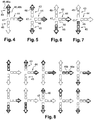
- one third of the air flow rate Q is blown by the second air circuit 12 and two thirds are blown by the first air circuit 11. As shown in figure 4 , this is represented on the display 41 by: one element 46 switched on in the second set 44, two elements 46 switched on in the first set 43, and no element switched on in the third set 45.
- the air sub flow rate Q3 in the third circuit 13 is one third of the air flow rate Q.
- one of the other sub flow rates is automatically decreased by the system so that Q remains substantially constant.
- it is the first sub flow rate Q1 which is decreased, the second sub flow rate Q2 remaining unchanged.
- the opposite solution could be envisaged.
- the first element of a set to be switched on is the arrowhead shaped element 46a, said element 46a also being the last element of the set to be switched off.
- one set always look like an arrow (provided the corresponding sub flow rate is not 0), the length of which being more or less long depending on the rate of the corresponding sub flow.
- an additional pressure on key 35 does not change the air distribution since the corresponding sub flow rate is already at its maximum value.
- the user can press the key of another air circuit until the corresponding sub flow rate has reached the desired level, in case the user wants to have air blown towards two distribution areas 21, 22, 23 of the cabin 1.
- figure 8 is illustrated an example of the set of air distributions that can be selected by the user by means of the system 4 according to the invention, said distributions being represented by the corresponding drawing on the display 41.
- the elements 46 with thick lines and which are hatched correspond to elements which are switched on, whereas elements 46 with thin lines and which are not hatched correspond to elements which are switched off. In practice, preferably, switched off elements 46 cannot be seen on the display 41, as shown in figure 2 .
- the system 4 makes it possible for the user, with only three buttons each button having a single action, to choose from ten different user defined air distributions which is a fairly high number as compared with conventional ventilation control systems.
- N of possible levels the more precise is the setting of the air distribution.
- some user defined air distributions can be not very different from other ones, which means that the system 4 allows a very precise setting of the air distribution.
- the system 4 provides intermediate air distributions as compared to conventional systems which only offer three or four possibilities to the user.
- This customization of the system is particularly positive for the driver in terms of comfort, perceived quality and brand image. Besides, the safety is improved since (i) the user only has to press a dedicated key instead of doing multiple actions, and (ii) the setting of the air distribution is intuitive and can be immediately and permanently checked on the display.
Landscapes
- Physics & Mathematics (AREA)
- Thermal Sciences (AREA)
- Engineering & Computer Science (AREA)
- Mechanical Engineering (AREA)
- Air-Conditioning For Vehicles (AREA)
Claims (14)
- Belüftungssteuerungssystem für eine Kabine (1) eines Fahrzeugs, wobei das System (4) umfasst:- eine Einheit (5), die einen in Richtung der Kabine (1) gerichteten Luftstrom (F) bereitstellen kann;- wenigstens einen ersten, zweiten und dritten Luftkreislauf (11, 12, 13), wobei jeder Luftkreislauf einen Luftunterstrom (F1, F2, F3) - der wenigstens einen Teil des Luftstroms (F) bildet - durch wenigstens eine Öffnung (17, 18, 19) in Richtung der Kabine (1) richten kann, wobei sich die Öffnungen des ersten, zweiten und dritten Luftkreislaufs jeweils in einem unterschiedlichen ersten, zweiten und dritten Verteilungsbereich (21, 22, 23) in der Kabine (1) befinden;- eine Verteilungseingabevorrichtung (32), die für jeden Luftkreislauf (11, 12, 13) ein zugeordnetes Steuerungselement (33, 34, 35) umfasst, um es dem Benutzer zu erlauben, die Rate (Q1, Q2, Q3) des Luftunterstroms (F1, F2, F3) in dem Luftkreislauf (11, 12, 13) manuell auszuwählen;- eine elektronische Steuereinheit (25), die mit der Verteilungseingabevorrichtung (32) verbunden ist und die Raten (Q1, Q2, Q3) der Luftunterströme (F1, F2, F3) gemäß der Rate (Q1, Q2, Q3) des für einen Luftkreislauf (11, 12, 13) manuell ausgewählten Luftunterstroms (F1, F2, F3) steuern kann,dadurch gekennzeichnet, dass die Verteilungseingabevorrichtung (32) nur ein zugeordnetes Steuerungselement (33, 34, 35) für jeden Luftkreislauf umfasst und die manuellen Betätigungen jedes zugeordneten Steuerungselements (33, 34, 35) nur Einwegs-Änderungen der Unterstromrate (Q1, Q2, Q3) in dem entsprechenden Luftkreislauf (11, 12, 13) bewirken können, so dass Raten (Q1, Q2, Q3) in anderen Luftkreisläufen (11, 12, 13) dann automatisch derart angepasst werden, dass die Summe aller Luftunterstromraten (Q1, Q2, Q3) im Wesentlichen konstant bleibt.
- System nach Anspruch 1, dadurch gekennzeichnet, dass die Verteilungseingabevorrichtung (32) und die elektronische Steuereinheit (25) so ausgelegt sind, dass eine manuelle Betätigung eines zugeordneten Steuerungselements (33, 34, 35) eine Erhöhung der Rate (Q1, Q2, Q3) des Luftunterstroms (F1, F2, F3) in dem entsprechenden Luftkreislauf (11, 12, 13) bewirkt.
- System nach Anspruch 1 oder 2, dadurch gekennzeichnet, dass das zugeordnete Steuerungselement jedes Luftkreislaufs (11, 12, 13) eine Taste ist und dass ein Druck auf eine zugeordnete Taste (33, 34, 35) eine Einwegs-Änderung der Rate (Q1, Q2, Q3) des Luftunterstroms (F1, F2, F3) in dem entsprechenden Luftkreislauf (11, 12, 13) bewirkt.
- System nach Anspruch 3, dadurch gekennzeichnet, dass ein Druck auf eine zugeordnete Taste (33, 34, 35) eine Erhöhung der Rate (Q1, Q2, Q3) des Luftunterstroms (F1, F2, F3) in dem entsprechenden Luftkreislauf (11, 12, 13) bewirkt.
- System nach Anspruch 2 oder 4, dadurch gekennzeichnet, dass die Verteilungseingabevorrichtung (32) und die elektronische Steuereinheit (25) so ausgelegt sind, dass eine manuelle Betätigung des zugeordneten Steuerungselements (33, 34, 35) ferner eine automatische Senkung der Rate (Q1, Q2, Q3) von wenigstens einem der anderen Luftunterströme (F1, F2, F3) bewirkt, wobei die Gesamtluftstromrate (Q) im Wesentlichen konstant bleibt.
- System nach einem der Ansprüche 1 bis 5, dadurch gekennzeichnet, dass, in Ansprechung auf eine manuelle Betätigung eines zugeordneten Steuerungselements (33, 34, 35), die elektronische Steuereinheit (25) dazu ausgelegt ist, die Änderung der Unterstromrate (Q1, Q2, Q3) in einem anderen oder mehreren anderen Luftkreisläufen (11, 12, 13) gemäß programmierter Regeln automatisch anzupassen.
- System nach einem der Ansprüche 1 bis 6, dadurch gekennzeichnet, dass jeder Luftkreislauf (11, 12, 13) mit wenigstens einer Stromsteuereinrichtung (26) ausgestattet ist, die durch die elektronische Steuereinheit (25) gesteuert wird, um die Rate (Q1, Q2, Q3) des entsprechenden Luftunterstroms (F1, F2, F3) gemäß der durch den Benutzer für einen Luftunterstrom (F1, F2, F3) manuell ausgewählten Rate (Q1, Q2, Q3) anzupassen, wobei die Rate (Q1, Q2, Q3) jedes Luftunterstroms individuell auf ein gewähltes Niveau unter N Niveaus eingestellt wird, wobei N ≥ 3, wobei die Summe aller Luftunterstromraten (Q1, Q2, Q3) gleich der Luftstromrate (Q) ist.
- System nach einem der Ansprüche 1 bis 7, dadurch gekennzeichnet, dass es eine Anzeige (41) umfasst, die die gegenwärtige Luftverteilung zeigen kann.
- System nach Anspruch 8, dadurch gekennzeichnet, dass die Anzeige (41), für jeden Luftkreislauf (11, 12, 13), einen Satz (43, 44, 45) von N Elementen (46, 46a, 46b) umfasst, wobei N ≥ 3, wobei die Anzahl von Elementen in einem Satz, die eingeschaltet sind, von der gegenwärtigen Unterstromrate (Q1, Q2, Q3) abhängt.
- System nach einem der Ansprüche 1 bis 9, dadurch gekennzeichnet, dass der erste Verteilungsbereich (21) die Windschutzscheibe (2) und/oder den Bereich des Kopfes des Kabineninsassen umfasst.
- System nach einem der Ansprüche 1 bis 10, dadurch gekennzeichnet, dass der zweite Verteilungsbereich (22) den Bereich des Oberkörpers des Kabineninsassen und/oder den vorderen Teil der Seitenfenster (3) umfasst.
- System nach einem der Ansprüche 1 bis 11, dadurch gekennzeichnet, dass der dritte Verteilungsbereich (23) den Bereich der Füße des Kabineninsassen und/oder den entlang des unteren Teils der Seitentüren befindlichen Bereich umfasst.
- Verfahren zum Steuern der Belüftung in einer Kabine (1) eines Fahrzeugs, das mit einem Belüftungssteuerungssystem (4) ausgestattet ist, das umfasst:- eine Einheit (5), die einen in Richtung der Kabine (1) gerichteten Luftstrom (F) bereitstellen kann;- wenigstens einen ersten, zweiten und dritten Luftkreislauf (11, 12, 13), wobei jeder Luftkreislauf einen Luftunterstrom (F1, F2, F3) - der wenigstens einen Teil des Luftstroms (F) bildet - durch wenigstens eine Öffnung (17, 18, 19) in Richtung der Kabine (1) richten kann, wobei sich die Öffnungen des ersten, zweiten und dritten Luftkreislaufs jeweils in einem unterschiedlichen ersten, zweiten und dritten Verteilungsbereich (21, 22, 23) in der Kabine (1) befinden;- ein zugeordnetes Steuerungselement (33, 34, 35) für jeden Luftkreislauf (11, 12, 13);- eine elektronische Steuereinheit (25), die mit einer Verteilungseingabevorrichtung (32) verbunden ist und die Raten (Q1, Q2, Q3) der Luftunterströme (F1, F2, F3) steuern kann,dadurch gekennzeichnet, dass das Verfahren die folgenden Schritte umfasst:a) Erfassen einer manuellen Betätigung eines zugeordneten Steuerungselements (33, 34, 35);b) abhängig von wenigstens der manuellen Betätigung des einen zugeordneten Steuerungselements und abhängig von dem gegenwärtigen Niveau der entsprechenden Unterstromrate, Bestimmen der neuen Unterstromrate (Q1, Q2, Q3), die von dem Benutzer gewünscht wird, in dem entsprechenden Luftkreislauf;c) Anpassen der Unterstromrate (Q1, Q2, Q3) in dem entsprechenden Luftkreislauf (11, 12, 13) gemäß der bestimmten Luftstromrate (Q1, Q2, Q3);d) Anpassen der Unterstromraten (Q1, Q2, Q3) in anderen Luftkreisläufen (11, 12, 13) abhängig von der bestimmten Luftstromrate und gemäß programmierter Regeln,und dadurch gekennzeichnet, dass die manuelle Betätigung des nur einen zugeordneten Steuerungselements (33, 34, 35) der Verteilungseingabevorrichtung (32) für jeden Luftkreislauf (11, 12, 13) nur eine Erhöhung der Unterstromrate (Q1, Q2, Q3) in dem entsprechenden Luftkreislauf (11, 12, 13) bewirkt und eine Senkung der Unterstromrate (Q1, Q2, Q3) in wenigstens einem anderen Kreislauf (11, 12, 13) bewirkt, so dass in Schritt d) Unterstromraten (Q1, Q2, Q3) in anderen Luftkreisläufen (11, 12, 13) automatisch derart angepasst werden, dass die Summe aller Luftunterstromraten (Q1, Q2, Q3) im Wesentlichen konstant bleibt.
- Verfahren nach Anspruch 13, dadurch gekennzeichnet, dass das zugeordnete Steuerungselement (33, 34, 35) für jeden Luftkreislauf (11, 12, 13) eine Taste ist und dass ein Druck auf eine zugeordnete Taste (33, 34, 35) eine Erhöhung der Rate (Q1, Q2, Q3) des Luftunterstroms (F1, F2, F3) in dem entsprechenden Luftkreislauf (11, 12, 13) bewirkt.
Applications Claiming Priority (1)
| Application Number | Priority Date | Filing Date | Title |
|---|---|---|---|
| PCT/IB2012/001190 WO2013171530A1 (en) | 2012-05-18 | 2012-05-18 | Ventilation control system and method for a cabin of a vehicle |
Publications (2)
| Publication Number | Publication Date |
|---|---|
| EP2849961A1 EP2849961A1 (de) | 2015-03-25 |
| EP2849961B1 true EP2849961B1 (de) | 2019-08-14 |
Family
ID=46514708
Family Applications (1)
| Application Number | Title | Priority Date | Filing Date |
|---|---|---|---|
| EP12735623.6A Active EP2849961B1 (de) | 2012-05-18 | 2012-05-18 | Belüftungssteuerungssystem und -verfahren für eine fahrzeugkabine |
Country Status (2)
| Country | Link |
|---|---|
| EP (1) | EP2849961B1 (de) |
| WO (1) | WO2013171530A1 (de) |
Families Citing this family (1)
| Publication number | Priority date | Publication date | Assignee | Title |
|---|---|---|---|---|
| CN107234938B (zh) * | 2017-07-05 | 2023-04-07 | 西南大学 | 一种汽车空调循环系统自适应调节装置 |
Family Cites Families (3)
| Publication number | Priority date | Publication date | Assignee | Title |
|---|---|---|---|---|
| DE4119475C2 (de) * | 1991-06-13 | 1998-01-22 | Opel Adam Ag | Einrichtung zum Regulieren der Luftzuführung in Kraftfahrzeugen aus einer Heiz- oder Klimaanlage |
| FR2749804B1 (fr) * | 1996-06-14 | 1998-09-04 | Valeo Climatisation | Installation de chauffage, ventilation et/ou climatisation, a regulation de debit d'air, notamment pour vehicule automobile |
| DE602008004527D1 (de) * | 2008-09-19 | 2011-02-24 | Fiat Ricerche | Benutzerschnittstelle für ein Belüftungs- oder Klimaanlagensystem für ein Kraftfahrzeug |
-
2012
- 2012-05-18 EP EP12735623.6A patent/EP2849961B1/de active Active
- 2012-05-18 WO PCT/IB2012/001190 patent/WO2013171530A1/en not_active Ceased
Non-Patent Citations (1)
| Title |
|---|
| None * |
Also Published As
| Publication number | Publication date |
|---|---|
| EP2849961A1 (de) | 2015-03-25 |
| WO2013171530A1 (en) | 2013-11-21 |
Similar Documents
| Publication | Publication Date | Title |
|---|---|---|
| CN111971191B (zh) | 用于控制用户界面和空气调节单元的方法和系统 | |
| CN102712233B (zh) | 用于空调装置的操作单元 | |
| CN108297644B (zh) | 用于机动车辆的通风系统和通风方法 | |
| US12508904B2 (en) | Display control apparatus and display control method | |
| US7788935B2 (en) | Automatic defogging system of vehicle and control method thereof | |
| CN101932884A (zh) | Hvac控制器 | |
| CA2619940A1 (en) | Thermostat including set point number line | |
| CN105270289A (zh) | 用户界面和借助用户界面显示单元调整行进器设置的方法 | |
| EP3666564A1 (de) | System und verfahren zur schätzung von klimabedürfnissen | |
| EP2849961B1 (de) | Belüftungssteuerungssystem und -verfahren für eine fahrzeugkabine | |
| CN102066141B (zh) | 配有自动供暖及空调装置的车辆空调系统 | |
| KR20190074623A (ko) | 차량용 공조장치 | |
| CN106467004B (zh) | 用于禁用车辆的各个座椅的脚部空间区域通风的方法和用于实施方法的装置 | |
| KR101695644B1 (ko) | 차량용 공조장치의 컨트롤러 | |
| US11225142B2 (en) | Method and device for controlling the air-conditioning function of a transportation vehicle seat | |
| WO2013093542A1 (en) | Thermal control system and method for a cabin of a vehicle | |
| US20070137850A1 (en) | Vehicle heating and/or air conditioning system and a method for regulating heating and/or air conditioning in vehicles | |
| KR101063456B1 (ko) | 차량 공조 최적화 시스템 및 방법 | |
| JP2005145327A (ja) | 車両用空調装置 | |
| JP3818080B2 (ja) | 車両用空調制御装置 | |
| US20200148026A1 (en) | Automatic cooling/heating control method of air conditioner for vehicle | |
| KR200389063Y1 (ko) | 차량의 맞춤형 전자동 온도 조절장치 | |
| CN107757294B (zh) | 用于控制车辆的暖通空调系统的方法 | |
| KR20000025483A (ko) | 반자동 타입의 온도 조절 방법 | |
| EP1577129A1 (de) | Bedieneinrichtung für eine Fahrzeugklimaanlage |
Legal Events
| Date | Code | Title | Description |
|---|---|---|---|
| PUAI | Public reference made under article 153(3) epc to a published international application that has entered the european phase |
Free format text: ORIGINAL CODE: 0009012 |
|
| 17P | Request for examination filed |
Effective date: 20141117 |
|
| AK | Designated contracting states |
Kind code of ref document: A1 Designated state(s): AL AT BE BG CH CY CZ DE DK EE ES FI FR GB GR HR HU IE IS IT LI LT LU LV MC MK MT NL NO PL PT RO RS SE SI SK SM TR |
|
| AX | Request for extension of the european patent |
Extension state: BA ME |
|
| DAX | Request for extension of the european patent (deleted) | ||
| RAP1 | Party data changed (applicant data changed or rights of an application transferred) |
Owner name: VOLVO LASTVAGNAR AB |
|
| STAA | Information on the status of an ep patent application or granted ep patent |
Free format text: STATUS: EXAMINATION IS IN PROGRESS |
|
| 17Q | First examination report despatched |
Effective date: 20171018 |
|
| GRAP | Despatch of communication of intention to grant a patent |
Free format text: ORIGINAL CODE: EPIDOSNIGR1 |
|
| STAA | Information on the status of an ep patent application or granted ep patent |
Free format text: STATUS: GRANT OF PATENT IS INTENDED |
|
| INTG | Intention to grant announced |
Effective date: 20190327 |
|
| GRAS | Grant fee paid |
Free format text: ORIGINAL CODE: EPIDOSNIGR3 |
|
| GRAA | (expected) grant |
Free format text: ORIGINAL CODE: 0009210 |
|
| STAA | Information on the status of an ep patent application or granted ep patent |
Free format text: STATUS: THE PATENT HAS BEEN GRANTED |
|
| AK | Designated contracting states |
Kind code of ref document: B1 Designated state(s): AL AT BE BG CH CY CZ DE DK EE ES FI FR GB GR HR HU IE IS IT LI LT LU LV MC MK MT NL NO PL PT RO RS SE SI SK SM TR |
|
| REG | Reference to a national code |
Ref country code: GB Ref legal event code: FG4D |
|
| REG | Reference to a national code |
Ref country code: CH Ref legal event code: EP Ref country code: AT Ref legal event code: REF Ref document number: 1166595 Country of ref document: AT Kind code of ref document: T Effective date: 20190815 |
|
| REG | Reference to a national code |
Ref country code: IE Ref legal event code: FG4D |
|
| REG | Reference to a national code |
Ref country code: DE Ref legal event code: R096 Ref document number: 602012062939 Country of ref document: DE |
|
| REG | Reference to a national code |
Ref country code: SE Ref legal event code: TRGR |
|
| REG | Reference to a national code |
Ref country code: NL Ref legal event code: MP Effective date: 20190814 |
|
| REG | Reference to a national code |
Ref country code: LT Ref legal event code: MG4D |
|
| PG25 | Lapsed in a contracting state [announced via postgrant information from national office to epo] |
Ref country code: PT Free format text: LAPSE BECAUSE OF FAILURE TO SUBMIT A TRANSLATION OF THE DESCRIPTION OR TO PAY THE FEE WITHIN THE PRESCRIBED TIME-LIMIT Effective date: 20191216 Ref country code: NO Free format text: LAPSE BECAUSE OF FAILURE TO SUBMIT A TRANSLATION OF THE DESCRIPTION OR TO PAY THE FEE WITHIN THE PRESCRIBED TIME-LIMIT Effective date: 20191114 Ref country code: FI Free format text: LAPSE BECAUSE OF FAILURE TO SUBMIT A TRANSLATION OF THE DESCRIPTION OR TO PAY THE FEE WITHIN THE PRESCRIBED TIME-LIMIT Effective date: 20190814 Ref country code: LT Free format text: LAPSE BECAUSE OF FAILURE TO SUBMIT A TRANSLATION OF THE DESCRIPTION OR TO PAY THE FEE WITHIN THE PRESCRIBED TIME-LIMIT Effective date: 20190814 Ref country code: HR Free format text: LAPSE BECAUSE OF FAILURE TO SUBMIT A TRANSLATION OF THE DESCRIPTION OR TO PAY THE FEE WITHIN THE PRESCRIBED TIME-LIMIT Effective date: 20190814 Ref country code: BG Free format text: LAPSE BECAUSE OF FAILURE TO SUBMIT A TRANSLATION OF THE DESCRIPTION OR TO PAY THE FEE WITHIN THE PRESCRIBED TIME-LIMIT Effective date: 20191114 Ref country code: NL Free format text: LAPSE BECAUSE OF FAILURE TO SUBMIT A TRANSLATION OF THE DESCRIPTION OR TO PAY THE FEE WITHIN THE PRESCRIBED TIME-LIMIT Effective date: 20190814 |
|
| REG | Reference to a national code |
Ref country code: AT Ref legal event code: MK05 Ref document number: 1166595 Country of ref document: AT Kind code of ref document: T Effective date: 20190814 |
|
| PG25 | Lapsed in a contracting state [announced via postgrant information from national office to epo] |
Ref country code: AL Free format text: LAPSE BECAUSE OF FAILURE TO SUBMIT A TRANSLATION OF THE DESCRIPTION OR TO PAY THE FEE WITHIN THE PRESCRIBED TIME-LIMIT Effective date: 20190814 Ref country code: LV Free format text: LAPSE BECAUSE OF FAILURE TO SUBMIT A TRANSLATION OF THE DESCRIPTION OR TO PAY THE FEE WITHIN THE PRESCRIBED TIME-LIMIT Effective date: 20190814 Ref country code: RS Free format text: LAPSE BECAUSE OF FAILURE TO SUBMIT A TRANSLATION OF THE DESCRIPTION OR TO PAY THE FEE WITHIN THE PRESCRIBED TIME-LIMIT Effective date: 20190814 Ref country code: IS Free format text: LAPSE BECAUSE OF FAILURE TO SUBMIT A TRANSLATION OF THE DESCRIPTION OR TO PAY THE FEE WITHIN THE PRESCRIBED TIME-LIMIT Effective date: 20191214 Ref country code: GR Free format text: LAPSE BECAUSE OF FAILURE TO SUBMIT A TRANSLATION OF THE DESCRIPTION OR TO PAY THE FEE WITHIN THE PRESCRIBED TIME-LIMIT Effective date: 20191115 Ref country code: ES Free format text: LAPSE BECAUSE OF FAILURE TO SUBMIT A TRANSLATION OF THE DESCRIPTION OR TO PAY THE FEE WITHIN THE PRESCRIBED TIME-LIMIT Effective date: 20190814 |
|
| PG25 | Lapsed in a contracting state [announced via postgrant information from national office to epo] |
Ref country code: TR Free format text: LAPSE BECAUSE OF FAILURE TO SUBMIT A TRANSLATION OF THE DESCRIPTION OR TO PAY THE FEE WITHIN THE PRESCRIBED TIME-LIMIT Effective date: 20190814 |
|
| PG25 | Lapsed in a contracting state [announced via postgrant information from national office to epo] |
Ref country code: IT Free format text: LAPSE BECAUSE OF FAILURE TO SUBMIT A TRANSLATION OF THE DESCRIPTION OR TO PAY THE FEE WITHIN THE PRESCRIBED TIME-LIMIT Effective date: 20190814 Ref country code: RO Free format text: LAPSE BECAUSE OF FAILURE TO SUBMIT A TRANSLATION OF THE DESCRIPTION OR TO PAY THE FEE WITHIN THE PRESCRIBED TIME-LIMIT Effective date: 20190814 Ref country code: PL Free format text: LAPSE BECAUSE OF FAILURE TO SUBMIT A TRANSLATION OF THE DESCRIPTION OR TO PAY THE FEE WITHIN THE PRESCRIBED TIME-LIMIT Effective date: 20190814 Ref country code: DK Free format text: LAPSE BECAUSE OF FAILURE TO SUBMIT A TRANSLATION OF THE DESCRIPTION OR TO PAY THE FEE WITHIN THE PRESCRIBED TIME-LIMIT Effective date: 20190814 Ref country code: EE Free format text: LAPSE BECAUSE OF FAILURE TO SUBMIT A TRANSLATION OF THE DESCRIPTION OR TO PAY THE FEE WITHIN THE PRESCRIBED TIME-LIMIT Effective date: 20190814 Ref country code: AT Free format text: LAPSE BECAUSE OF FAILURE TO SUBMIT A TRANSLATION OF THE DESCRIPTION OR TO PAY THE FEE WITHIN THE PRESCRIBED TIME-LIMIT Effective date: 20190814 |
|
| PG25 | Lapsed in a contracting state [announced via postgrant information from national office to epo] |
Ref country code: CZ Free format text: LAPSE BECAUSE OF FAILURE TO SUBMIT A TRANSLATION OF THE DESCRIPTION OR TO PAY THE FEE WITHIN THE PRESCRIBED TIME-LIMIT Effective date: 20190814 Ref country code: SM Free format text: LAPSE BECAUSE OF FAILURE TO SUBMIT A TRANSLATION OF THE DESCRIPTION OR TO PAY THE FEE WITHIN THE PRESCRIBED TIME-LIMIT Effective date: 20190814 Ref country code: IS Free format text: LAPSE BECAUSE OF FAILURE TO SUBMIT A TRANSLATION OF THE DESCRIPTION OR TO PAY THE FEE WITHIN THE PRESCRIBED TIME-LIMIT Effective date: 20200224 Ref country code: SK Free format text: LAPSE BECAUSE OF FAILURE TO SUBMIT A TRANSLATION OF THE DESCRIPTION OR TO PAY THE FEE WITHIN THE PRESCRIBED TIME-LIMIT Effective date: 20190814 |
|
| REG | Reference to a national code |
Ref country code: DE Ref legal event code: R097 Ref document number: 602012062939 Country of ref document: DE |
|
| PLBE | No opposition filed within time limit |
Free format text: ORIGINAL CODE: 0009261 |
|
| STAA | Information on the status of an ep patent application or granted ep patent |
Free format text: STATUS: NO OPPOSITION FILED WITHIN TIME LIMIT |
|
| PG2D | Information on lapse in contracting state deleted |
Ref country code: IS |
|
| 26N | No opposition filed |
Effective date: 20200603 |
|
| PG25 | Lapsed in a contracting state [announced via postgrant information from national office to epo] |
Ref country code: SI Free format text: LAPSE BECAUSE OF FAILURE TO SUBMIT A TRANSLATION OF THE DESCRIPTION OR TO PAY THE FEE WITHIN THE PRESCRIBED TIME-LIMIT Effective date: 20190814 |
|
| PG25 | Lapsed in a contracting state [announced via postgrant information from national office to epo] |
Ref country code: MC Free format text: LAPSE BECAUSE OF FAILURE TO SUBMIT A TRANSLATION OF THE DESCRIPTION OR TO PAY THE FEE WITHIN THE PRESCRIBED TIME-LIMIT Effective date: 20190814 Ref country code: CH Free format text: LAPSE BECAUSE OF NON-PAYMENT OF DUE FEES Effective date: 20200531 Ref country code: LI Free format text: LAPSE BECAUSE OF NON-PAYMENT OF DUE FEES Effective date: 20200531 |
|
| REG | Reference to a national code |
Ref country code: BE Ref legal event code: MM Effective date: 20200531 |
|
| GBPC | Gb: european patent ceased through non-payment of renewal fee |
Effective date: 20200518 |
|
| PG25 | Lapsed in a contracting state [announced via postgrant information from national office to epo] |
Ref country code: LU Free format text: LAPSE BECAUSE OF NON-PAYMENT OF DUE FEES Effective date: 20200518 |
|
| PG25 | Lapsed in a contracting state [announced via postgrant information from national office to epo] |
Ref country code: GB Free format text: LAPSE BECAUSE OF NON-PAYMENT OF DUE FEES Effective date: 20200518 Ref country code: IE Free format text: LAPSE BECAUSE OF NON-PAYMENT OF DUE FEES Effective date: 20200518 |
|
| PG25 | Lapsed in a contracting state [announced via postgrant information from national office to epo] |
Ref country code: BE Free format text: LAPSE BECAUSE OF NON-PAYMENT OF DUE FEES Effective date: 20200531 |
|
| PG25 | Lapsed in a contracting state [announced via postgrant information from national office to epo] |
Ref country code: MT Free format text: LAPSE BECAUSE OF FAILURE TO SUBMIT A TRANSLATION OF THE DESCRIPTION OR TO PAY THE FEE WITHIN THE PRESCRIBED TIME-LIMIT Effective date: 20190814 Ref country code: CY Free format text: LAPSE BECAUSE OF FAILURE TO SUBMIT A TRANSLATION OF THE DESCRIPTION OR TO PAY THE FEE WITHIN THE PRESCRIBED TIME-LIMIT Effective date: 20190814 |
|
| PG25 | Lapsed in a contracting state [announced via postgrant information from national office to epo] |
Ref country code: MK Free format text: LAPSE BECAUSE OF FAILURE TO SUBMIT A TRANSLATION OF THE DESCRIPTION OR TO PAY THE FEE WITHIN THE PRESCRIBED TIME-LIMIT Effective date: 20190814 |
|
| PGFP | Annual fee paid to national office [announced via postgrant information from national office to epo] |
Ref country code: SE Payment date: 20240527 Year of fee payment: 13 |
|
| PGFP | Annual fee paid to national office [announced via postgrant information from national office to epo] |
Ref country code: DE Payment date: 20250528 Year of fee payment: 14 |
|
| PGFP | Annual fee paid to national office [announced via postgrant information from national office to epo] |
Ref country code: FR Payment date: 20250526 Year of fee payment: 14 |
|
| PG25 | Lapsed in a contracting state [announced via postgrant information from national office to epo] |
Ref country code: SE Free format text: LAPSE BECAUSE OF NON-PAYMENT OF DUE FEES Effective date: 20250519 |
|
| REG | Reference to a national code |
Ref country code: SE Ref legal event code: EUG |