EP2850397B1 - Compteur sans batterie pour milieux en écoulement - Google Patents
Compteur sans batterie pour milieux en écoulement Download PDFInfo
- Publication number
- EP2850397B1 EP2850397B1 EP13723404.3A EP13723404A EP2850397B1 EP 2850397 B1 EP2850397 B1 EP 2850397B1 EP 13723404 A EP13723404 A EP 13723404A EP 2850397 B1 EP2850397 B1 EP 2850397B1
- Authority
- EP
- European Patent Office
- Prior art keywords
- wiegand
- magnetic field
- sensor
- battery
- flowing medium
- Prior art date
- Legal status (The legal status is an assumption and is not a legal conclusion. Google has not performed a legal analysis and makes no representation as to the accuracy of the status listed.)
- Active
Links
Images

Classifications
-
- G—PHYSICS
- G01—MEASURING; TESTING
- G01F—MEASURING VOLUME, VOLUME FLOW, MASS FLOW OR LIQUID LEVEL; METERING BY VOLUME
- G01F1/00—Measuring the volume flow or mass flow of fluid or fluent solid material wherein the fluid passes through a meter in a continuous flow
- G01F1/56—Measuring the volume flow or mass flow of fluid or fluent solid material wherein the fluid passes through a meter in a continuous flow by using electric or magnetic effects
- G01F1/58—Measuring the volume flow or mass flow of fluid or fluent solid material wherein the fluid passes through a meter in a continuous flow by using electric or magnetic effects by electromagnetic flowmeters
- G01F1/586—Measuring the volume flow or mass flow of fluid or fluent solid material wherein the fluid passes through a meter in a continuous flow by using electric or magnetic effects by electromagnetic flowmeters constructions of coils, magnetic circuits, accessories therefor
-
- G—PHYSICS
- G01—MEASURING; TESTING
- G01F—MEASURING VOLUME, VOLUME FLOW, MASS FLOW OR LIQUID LEVEL; METERING BY VOLUME
- G01F1/00—Measuring the volume flow or mass flow of fluid or fluent solid material wherein the fluid passes through a meter in a continuous flow
- G01F1/05—Measuring the volume flow or mass flow of fluid or fluent solid material wherein the fluid passes through a meter in a continuous flow by using mechanical effects
- G01F1/06—Measuring the volume flow or mass flow of fluid or fluent solid material wherein the fluid passes through a meter in a continuous flow by using mechanical effects using rotating vanes with tangential admission
- G01F1/075—Measuring the volume flow or mass flow of fluid or fluent solid material wherein the fluid passes through a meter in a continuous flow by using mechanical effects using rotating vanes with tangential admission with magnetic or electromagnetic coupling to the indicating device
-
- G—PHYSICS
- G01—MEASURING; TESTING
- G01F—MEASURING VOLUME, VOLUME FLOW, MASS FLOW OR LIQUID LEVEL; METERING BY VOLUME
- G01F1/00—Measuring the volume flow or mass flow of fluid or fluent solid material wherein the fluid passes through a meter in a continuous flow
- G01F1/05—Measuring the volume flow or mass flow of fluid or fluent solid material wherein the fluid passes through a meter in a continuous flow by using mechanical effects
- G01F1/10—Measuring the volume flow or mass flow of fluid or fluent solid material wherein the fluid passes through a meter in a continuous flow by using mechanical effects using rotating vanes with axial admission
- G01F1/115—Measuring the volume flow or mass flow of fluid or fluent solid material wherein the fluid passes through a meter in a continuous flow by using mechanical effects using rotating vanes with axial admission with magnetic or electromagnetic coupling to the indicating device
-
- G—PHYSICS
- G01—MEASURING; TESTING
- G01F—MEASURING VOLUME, VOLUME FLOW, MASS FLOW OR LIQUID LEVEL; METERING BY VOLUME
- G01F15/00—Details of, or accessories for, apparatus of groups G01F1/00 - G01F13/00 insofar as such details or appliances are not adapted to particular types of such apparatus
- G01F15/14—Casings, e.g. of special material
Definitions
- the invention relates to a battery-free meter for flowing media according to the preamble of claim 1.
- Wiegand sensor is synonymous with the term “pulse wire motion sensor”.
- Pulse wire motion sensor is synonymous with the term “pulse wire motion sensor”.
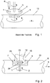
- FIG. 1 In the FIG. 1 is shown as prior art, a rotation angle sensor in which a permanent magnet-occupied disc is rotatably driven by the fluid flow.
- the magnetic field lines pass through the media bulkhead and drive a second magnet, which is carried along by the first rotating magnetic field via a magnetic coupling, so as to detect a Wiegand sensor by scanning the second off-center rotating magnet this area. This allows a battery-free supply of the circuit.
- FIG. 1 Another disadvantage of the prior art after FIG. 1 is that moving parts are arranged in the outer area, which is undesirable.
- a batterieloser counter for flowing media disclosed in which in the flowing medium pipe leading a permanent magnet occupied by the medium rotatably driven rotor body is arranged and the thus generated, rotating magnetic field acts on a Wiegand sensor, the outside of the flowing Medium is arranged in the surrounding area of the counter, wherein transversely to the longitudinal axis of the pipe in this pipe, a housing part engages sealingly into the interior of the pipe and flows around the flowing medium, that the outer periphery of the housing part of the rotationally driven, the rotating magnetic field generating rotor part is included , And that in the housing part a Wiegand sensor is arranged.
- a disadvantage of this prior art is that only a Wiegand sensor is used for flow measurement. In case of failure of a Wiegand sensor you would have to disassemble the measuring device to repair the complete failure of the measuring system.
- the counter shown here is only suitable for the generation of a magnetic field to generate the magnetic pulses of only a Wiegand sensor.
- the invention is therefore based on the object, a batteryless counter for flowing media, in particular gas or water, so educate, that outside the flowing medium no rotatable parts are arranged and a magnetic influence applied from the outside does not lead to an impairment of the counting function. Furthermore, the counter should have a high reliability.
- the invention is characterized by the technical teaching of claim 1.
- the basic function of the invention is that a flowing medium drives a mechanism which generates a movement (preferably rotational movement). This (rotational) movement is used to change a magnetic field or the magnetic field direction. Either magnets are connected to the motion element or the sensor moves with fixed magnets.
- the Wiegand sensors detect these magnetic field direction changes and produce a current pulse with each change.
- This current pulse is detected by a circuit and counted.
- the current count is stored in the circuit and can later be read by external readout devices and further processed (eg transmitted by radio or displayed in the classic display).
- the current pulses of the Wiegand sensors suffice as a power supply to the circuit for these operations; the circuit therefore works without external power supply.
- the magnetic field design is set for optimal use (working temperature, field strength, field homogeneity, etc.).
- the circuit can be operated with the Wiegand energy generated more sensor elements.
- additional sensor elements eg Hall sensor
- the detection of the direction of rotation is additionally possible.
- the count stored at each pulse in the circuit is changed by one positive or negative counting step.
- a safety monitoring can be realized. This can be z. B. by comparing the counts of redundant systems with at least two independently working Wiegand sensors.
- An essential feature of the invention is therefore that a housing extends sealingly into the interior of the flowing medium, in which housing preferably two Wiegand sensors are arranged, and that in the flowing medium only the moving with permanent magnets, preferably designed as a sleeve disc is arranged, the produces a necessary magnetic field with respect to the Wiegand sensors sealingly engaging the flowing medium on the housing side.
- the housing accommodates in its interior the sensors with the Wiegand sensors and extends with its longitudinal axis approximately transversely (approximately at an angle of 90 degrees) to the longitudinal axis of the pipeline into this pipeline.
- the interior of the housing is therefore not acted upon by the medium, but by the atmosphere surrounding the pipe. It may therefore be preferably designed to be open on one side in the direction of the atmosphere, in order to obtain good access for the sensors installed there.
- transversal magnetic field is understood to mean that a rotating magnetic field is generated whose field lines extend parallel to the flowing medium and thereby rotate, ie a rotational magnetic field is generated in the plane of the Wiegand wires, with the advantage that In a confined space not only a single Wiegand sensor can be arranged, but two Wiegand sensors, or even more, all of the same transversal Magnetic field are interspersed with about the same magnetic field strength, which was not possible in the prior art.
- the one or more Wiegand sensors were arranged vertically one above the other (stacked), while the focus of the present invention is that the Wiegand sensors with the aligned in this plane Wiegand wires flows through a radially outwardly of the housing arranged magnetic field become.
- the invention provides a vertical, in-plane arrangement of the Wiegand sensors.
- FIG. 1 is shown schematically according to the prior art that a permanent magnet occupied disk a in the flowing medium 8 rotates and in this case generates a magnetic field through the partition wall 13 of the medium on a disposed outside the medium further rotatable disk b, with one or more permanent magnets c is occupied, wherein between the disc a and the disc b is a magnetic rotary coupling.
- the disc b Due to the rotation of the disc a, the disc b is rotationally driven via the magnetic coupling and a Wiegand sensor d is arranged near the disc b, whose Wiegand wire is acted upon by the permanent magnet field of the permanent magnet c, so that a voltage pulse is generated when the field direction changes.
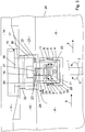
- FIG. 2 the basic principle of the invention is shown.
- a housing part 15 with an inner bush 12 dips into the flowing medium 8.
- two spaced Wiegand sensors 25, 26 are preferably arranged, which are interspersed by the transverse magnetic field - field lines 29 -.
- the transverse magnetic field is generated by a plurality of evenly distributed around the circumference arranged permanent magnet 6, 7, which are arranged on a sleeve 4 are, for example, rotates in the direction of arrow 2 and is rotatably connected to a drive shaft 1.
- the drive of the drive shaft 1 via a non-illustrated drive device for.
- a turbine wheel or the like which may be arranged directly in the flowing medium 8.
- Another advantage of the invention is that it is now possible because of the parallel arrangement of the field lines 29 in a plane (parallel to the flow direction of the flowing medium 8) to arrange in this plane two or more superimposed Wiegand sensors 25, 26, all in flow through the field lines 29 of the rotational magnetic field in the same way, because they lie substantially one above the other in a plane vertically.
- one or more Hall sensors are provided, with which the direction of rotation can be detected.
- an additional magnetic field is still arranged in the housing-fixed part, that is to say, H. inside the case.
- a direction of rotation detection is provided, to which at least one Wiegand sensor in combination with a Hall sensor is necessary.
- the invention provides that two Wiegand sensors are present and each Wiegand sensor is associated with a respective Hall sensor.
- FIG. 3 is shown that a drive shaft 1 is present in the flowing medium 8, which flows, for example, in the direction of arrow 9.
- the drive shaft 1 can in this case in the direction of arrow 2, but also in the opposite direction, in the direction of arrow 3, to be driven.
- the drive shaft 1 is preferably material integral with a cup-shaped sleeve 4, at the outer periphery of a number of permanent magnets 6, 7 are arranged evenly distributed around the circumference.
- a number of permanent magnets 6, 7 are arranged evenly distributed around the circumference.
- two oppositely arranged permanent magnets 6, 7 are arranged on the outer circumference.
- more than two permanent magnets may be provided.
- a permanent magnet 6 points radially outwards with its north pole, while the opposite permanent magnet 7 points radially outward with its south pole. These are polar opposites.
- the two existing permanent magnets 6, 7 may also in pairs more Permanent magnets are arranged; ie for example four permanent magnets or six or eight.
- These permanent magnets 6 are each arranged distributed in the circumference arranged pockets 5 in the wall of the sleeve 4 and generate a transverse field, as it is with the field lines 29 in FIG. 4 is shown. This is also in FIG. 3 shown. There it can be seen that the rotating field, which is generated by the rotating sleeve 4, transversally passes through the inner housing 15, which makes up the meter.
- the housing part 15 is sealed inserted into a partition wall 13 and extends with a sleeve-shaped housing part (inner sleeve 12) sealed in the flowing medium 8 inside.
- the interior 18 of the housing communicates with the neutral environment 14 and does not need to be (especially) sealed. This is a significant advantage over the prior art.
- the rotationally driven sleeve 4 rotates via a ring-shaped annular gap 10 and a bottom gap 11 in relation to the stationary inner sleeve 12.
- a number of permanent magnets 24, 24a are rotatably arranged on the outer circumference, which form the signal generator for the arranged in the interior 18 of the housing 15 Hall sensors 21, 22, which are used for detecting the direction of rotation.
- Each Hall sensor 21, 22 is independent of the other and performs independent evaluation to achieve the previously named redundant and independently operating systems.
- a first system is generated, for example, by the upper Wiegand sensor 25 in conjunction with, for example, the Hall sensor 21, while the second, independently evaluating and also independently operating measuring system is formed from the second Wiegand sensor 26 in conjunction with the Hall sensor 22 becomes.
- the measuring sensors are assigned redundant evaluation electronics, which are not mentioned here.
- the two Wiegand sensors 25, 26 are separated from each other in the interior of the inner sleeve 12 by connecting pins 23. It is a middle circuit board 27 is provided, on which the two Wiegand sensors 25, 26 are arranged. It is only shown by way of example that each Wiegand sensor 25, 26 in a conventional manner, a Wiegand wire 28 is assigned, in which the electrical voltage is induced.
- the inner bush 12 is made of material in one piece in the form of a wall bushing 16 with an enlarged diameter upwards, wherein the wall bushing 16 is received with an external thread 17 sealingly in an associated receiving bore 33 of the partition wall 13.
- a further printed circuit board 20 is arranged over the connecting pins 23, which carries a terminal block 19, in which the measuring electronics and the connection parts are integrated.
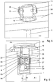
- FIG. 5 another embodiment is shown. This embodiment differs from the embodiment FIG. 3 in that the components are positioned differently.
- the Wiegand sensors 25, 26 are arranged in a narrower space and are held by connecting pins 23 at a distance.
- a printed circuit board 27 is present, below which a Hall sensor 21 is arranged via a further printed circuit board 30, while the opposite Hall sensor is connected to an upper printed circuit board 20 in the region of an upper printed circuit board 30 in the form of the Hall.
- Sensor 22 is arranged.
- the two Hall sensors 21, 22 are therefore offset from one another obliquely to each other at different heights and work with each arranged on these levels permanent magnets, which are each arranged rotationally fixed in the circumferentially driven sleeve 4.
- the permanent magnets are not shown for the sake of simplicity.
- FIG. 5 shows that the proportion of the housing 15, which dips in the form of the inner sleeve 12 in the medium 8, is greater than in the embodiment according to comparatively FIG. 3 and that in the embodiment according to FIG. 5 in the outer area beyond the partition 13, only small-sized housing parts are present.
- FIG. 6 Another embodiment is in FIG. 6 shown. This embodiment is not part of the invention but is for further explanation and to facilitate understanding of the invention. It is on the other side of the partition 13, a high-build housing part 15 is provided, on the outer circumference of the Wiegand sensors 25, 26 are arranged, which are arranged in the interior of the housing in the previous example.
- the Wiegand sensors can also be arranged outside the housing and are influenced by the permanent magnets 6, 7, which are arranged in an inner circumferential sleeve within the housing 15.
- the contrasting construction compared to FIG. 5 given because the essential part of the housing structure is arranged in the region of the neutral environment 14, while FIG. 5 the essential part of the housing structure is arranged in the region of the flowing medium 8.
- the diameter of the housing 15 can be further minimized because the Wiegand sensors sit radially outward and there is no need - as in FIG. 5 - To install the Wiegand sensors expansive in the area of an immersed in the medium and sealed there inner sleeve 12.
- FIG. 6 can be a significant minimization of the housing dimensions compared to the case after FIG. 5 be made.
Landscapes
- Physics & Mathematics (AREA)
- Fluid Mechanics (AREA)
- General Physics & Mathematics (AREA)
- Electromagnetism (AREA)
- Engineering & Computer Science (AREA)
- Power Engineering (AREA)
- Measuring Volume Flow (AREA)
Claims (8)
- Compteur sans batterie pour des milieux en écoulement, dans lequel un corps de rotor (4) équipé d'aimants permanents (6, 7) entraîné en rotation par le milieu est disposé dans le conduit tubulaire (34) acheminant le milieu (8) en écoulement et le champ magnétique rotatif ainsi généré agit sur un capteur Wiegand (25), qui est disposé à l'extérieur du milieu en écoulement dans la zone environnante du compteur, dans lequel une partie de boîtier (15) vient en prise de manière étanche avec l'espace intérieur du conduit tubulaire (34) dans ledit conduit tubulaire (34) approximativement transversalement par rapport à l'axe longitudinal du conduit tubulaire (34) et est entourée au moins en partie du milieu en écoulement, que la périphérie extérieure de la partie de boîtier (15) est comprise au moins en partie par le corps de rotor (4) entraîné en rotation générant le champ magnétique rotatif, et que le capteur Wiegand (25) est disposé dans la partie de boîtier (15), caractérisé en ce qu'un deuxième capteur Wiegand (26) est présent, qui est indépendant du premier capteur Wiegand (25), dans lequel les deux capteurs Wiegand (25, 26) sont disposés de manière superposée parallèlement à la direction de flux du milieu (8) en écoulement, dans lequel le champ magnétique rotatif généré par les aimants permanents (6, 7) est orienté avec ses lignes de champ (29) parallèlement à la direction de flux du milieu (8) en écoulement, et le champ magnétique rotatif ainsi formé se situe dans le plan des capteurs Wiegand (25, 26), qui, tous deux, sont traversés par le même champ magnétique transversal avec à peu près la même intensité de champ magnétique.
- Compteur sans batterie selon la revendication 1, caractérisé en ce qu'un élément de capteur d'identification de direction de rotation est présent sous la forme d'un ou de plusieurs capteurs à effet Hall (21, 22), lequel est traversé par les lignes de champ (29) du champ magnétique permanent rotatif dans le plan ou la direction (9) du milieu (8) en écoulement.
- Compteur sans batterie selon la revendication 1 ou 2, caractérisé en ce que seulement le corps de rotor équipé d'aimants permanents (6, 7) est disposé sous la forme d'une douille (4) dans le milieu en écoulement, et que les aimants permanents (6, 7) génèrent un champ magnétique par rapport aux capteurs Wiegand (25, 26) venant en prise de manière étanche côté boîtier avec le milieu (8) en écoulement.
- Compteur sans batterie selon l'une des revendications 1 à 3, caractérisé en ce que les impulsions de courant des capteurs Wiegand (25, 26) sont utilisées pour l'alimentation en courant du circuit du compteur.
- Compteur sans batterie selon l'une des revendications 1 à 4, caractérisé en ce que les deux capteurs Wiegand (25, 26) sont reliés à des circuits associés, qui réalisent une structure de circuit redondante.
- Compteur sans batterie selon l'une des revendications 1 à 5, caractérisé en ce que pour chaque capteur Wiegand (25, 26) et pour chaque capteur à effet Hall (21, 22) associé, une évaluation de mesure est effectuée de sorte que deux évaluations de mesure séparées soient présentes, qui sont comparées l'une à l'autre.
- Compteur sans batterie selon l'une des revendications 1 à 6, caractérisé en ce que l'arbre d'entraînement (1) disposé dans le milieu (8) en écoulement est relié à la douille (4) en forme de pot, au niveau de la périphérie extérieure de laquelle un nombre d'aimants permanents (6, 7) sont disposés de manière répartie uniformément au niveau de la périphérie.
- Compteur sans batterie selon la revendication 7, caractérisé en ce que les aimants permanents (6, 7) présentent une polarité opposée, dans lequel un aimant permanent (6) pointe avec son pôle nord radialement vers l'extérieur alors que l'aimant permanent (7) opposé pointe avec son pôle sud vers l'extérieur radialement.
Applications Claiming Priority (2)
| Application Number | Priority Date | Filing Date | Title |
|---|---|---|---|
| DE102012009962A DE102012009962A1 (de) | 2012-05-19 | 2012-05-19 | Batterieloser Zähler für strömende Medien |
| PCT/EP2013/001249 WO2013174469A2 (fr) | 2012-05-19 | 2013-04-25 | Compteur sans batterie pour milieux en écoulement |
Publications (2)
| Publication Number | Publication Date |
|---|---|
| EP2850397A2 EP2850397A2 (fr) | 2015-03-25 |
| EP2850397B1 true EP2850397B1 (fr) | 2019-06-12 |
Family
ID=48463910
Family Applications (1)
| Application Number | Title | Priority Date | Filing Date |
|---|---|---|---|
| EP13723404.3A Active EP2850397B1 (fr) | 2012-05-19 | 2013-04-25 | Compteur sans batterie pour milieux en écoulement |
Country Status (6)
| Country | Link |
|---|---|
| US (1) | US20150135852A1 (fr) |
| EP (1) | EP2850397B1 (fr) |
| CN (1) | CN104471357A (fr) |
| CA (1) | CA2873702C (fr) |
| DE (1) | DE102012009962A1 (fr) |
| WO (1) | WO2013174469A2 (fr) |
Families Citing this family (12)
| Publication number | Priority date | Publication date | Assignee | Title |
|---|---|---|---|---|
| DE102015117064B4 (de) * | 2015-09-28 | 2023-06-07 | Avago Technologies International Sales Pte. Limited | Positionsdetektor |
| JP6659199B2 (ja) * | 2016-03-18 | 2020-03-04 | 東フロコーポレーション株式会社 | 流量計 |
| CN105758472A (zh) * | 2016-04-07 | 2016-07-13 | 福建国仪上润投资有限公司 | 可判断流体流向的磁感应脉冲流量计量装置 |
| CN105737915A (zh) * | 2016-04-07 | 2016-07-06 | 福建国仪上润投资有限公司 | 可测温压的磁感应脉冲计量水表 |
| CN107168160B (zh) * | 2017-05-24 | 2019-04-26 | 广东盈动高科自动化有限公司 | 基于韦根传感器的多圈计数方法及多圈计数装置 |
| WO2018222210A1 (fr) | 2017-06-02 | 2018-12-06 | Halliburton Energy Services, Inc. | Surveillance de rotation avec film magnétique |
| US20200284627A1 (en) * | 2017-09-07 | 2020-09-10 | Toflo Corporation | Flowmeter |
| DE102018101568A1 (de) | 2018-01-24 | 2019-07-25 | Krohne Ag | Magnetisch-induktives Durchflussmessgerät |
| JP7288952B2 (ja) * | 2018-08-09 | 2023-06-08 | マイクロ モーション インコーポレイテッド | 防爆性のフィードスルー |
| DE102019116636A1 (de) | 2019-06-19 | 2020-12-24 | Fraba B.V. | Sensorvorrichtung und Fluiddurchfluss-Messanordnung mit einer derartigen Sensorvorrichtung |
| US11988538B2 (en) | 2022-08-18 | 2024-05-21 | Ideavipu Oy | Water meter powered by energy produced from fluid flow pressure changes |
| DE102024120359A1 (de) * | 2024-07-18 | 2026-01-22 | Ebm-Papst Mulfingen Gmbh & Co. Kg | Vorrichtung und verfahren zur volumenstrom- und qualitätsbestimmung |
Citations (2)
| Publication number | Priority date | Publication date | Assignee | Title |
|---|---|---|---|---|
| DE102007039050A1 (de) * | 2007-08-17 | 2009-02-26 | Mehnert, Walter, Dr. | Linearsegment- oder Umdrehungszähler mit einem ferromagnetischen Element |
| EP2159547A2 (fr) * | 2008-08-30 | 2010-03-03 | Walter Mehnert | Bloc de capteurs pour un encodeur et encodeur pourvu d'un tel bloc de capteurs |
Family Cites Families (16)
| Publication number | Priority date | Publication date | Assignee | Title |
|---|---|---|---|---|
| US3731533A (en) * | 1969-10-16 | 1973-05-08 | Dresser Ind | Electrical generator having non-salient poles for metering shaft rotation of a turbine assembly |
| GB2102129A (en) * | 1981-07-17 | 1983-01-26 | Flight Refueling Ltd | Fluid flow meters using Wiegand effect devices |
| DE3305316A1 (de) * | 1983-02-16 | 1984-08-23 | BHT Hygiene Technik GmbH, 8900 Augsburg | Spuelmaschine |
| DE3538514A1 (de) * | 1985-10-30 | 1987-05-07 | Bopp & Reuther Gmbh | Elektromagnetischer impulsaufnehmer fuer durchflussmesser |
| FR2664973B1 (fr) * | 1990-07-20 | 1992-10-23 | Schlumberger Ind Sa | Dispositif de detection de rotation d'un element tournant tel que la turbine d'un compteur d'eau. |
| DE4114978A1 (de) * | 1991-05-08 | 1992-11-12 | Allmess Mess Regelgeraete | Fluidzaehler, insbesondere wasserzaehler |
| DE4407474C2 (de) | 1994-03-07 | 2000-07-13 | Asm Automation Sensorik Messte | Drehwinkelsensor |
| DE19714351C2 (de) * | 1997-03-26 | 1999-01-28 | Rmg Gaselan Regel & Mestechnik | Verfahren und Vorrichtung zum Erfassen von Gas- und Flüssigkeitsvolumina mit Volumenzählern |
| US6604434B1 (en) * | 2000-06-23 | 2003-08-12 | Neptune Technology Group, Inc. | Method and apparatus for determining the direction and rate of a rotating element |
| US6612188B2 (en) * | 2001-01-03 | 2003-09-02 | Neptune Technology Group Inc. | Self-powered fluid meter |
| DE20211983U1 (de) * | 2002-08-03 | 2002-10-24 | E. Wehrle GmbH, 78120 Furtwangen | Durchflußmeßgerät mit Turbinen-Meßrad |
| FR2847339B1 (fr) * | 2002-11-14 | 2005-03-04 | Thierry Sartorius | Systeme et appareil de surveillance d'un debit de fluide dans une canalisation |
| CN2804807Y (zh) * | 2005-04-23 | 2006-08-09 | 杨晖 | 采用韦根传感器的高精度计量表芯 |
| CN2864613Y (zh) * | 2005-08-10 | 2007-01-31 | 陈伟平 | 韦根传感的水表装置 |
| DE102008039272B4 (de) * | 2008-08-23 | 2021-08-26 | Amphiro Ag | Verfahren zur Ermittlung des Ressourcenverbrauches |
| CA2769749C (fr) * | 2009-07-31 | 2017-06-06 | Capstone Metering Llc | Compteur d'eau auto-etalonne et auto-alimente |
-
2012
- 2012-05-19 DE DE102012009962A patent/DE102012009962A1/de not_active Ceased
-
2013
- 2013-04-25 WO PCT/EP2013/001249 patent/WO2013174469A2/fr not_active Ceased
- 2013-04-25 CN CN201380026262.9A patent/CN104471357A/zh active Pending
- 2013-04-25 CA CA2873702A patent/CA2873702C/fr not_active Expired - Fee Related
- 2013-04-25 EP EP13723404.3A patent/EP2850397B1/fr active Active
- 2013-04-25 US US14/402,227 patent/US20150135852A1/en not_active Abandoned
Patent Citations (2)
| Publication number | Priority date | Publication date | Assignee | Title |
|---|---|---|---|---|
| DE102007039050A1 (de) * | 2007-08-17 | 2009-02-26 | Mehnert, Walter, Dr. | Linearsegment- oder Umdrehungszähler mit einem ferromagnetischen Element |
| EP2159547A2 (fr) * | 2008-08-30 | 2010-03-03 | Walter Mehnert | Bloc de capteurs pour un encodeur et encodeur pourvu d'un tel bloc de capteurs |
Also Published As
| Publication number | Publication date |
|---|---|
| EP2850397A2 (fr) | 2015-03-25 |
| WO2013174469A2 (fr) | 2013-11-28 |
| CA2873702A1 (fr) | 2013-11-28 |
| WO2013174469A3 (fr) | 2014-01-23 |
| DE102012009962A1 (de) | 2013-11-21 |
| CN104471357A (zh) | 2015-03-25 |
| US20150135852A1 (en) | 2015-05-21 |
| CA2873702C (fr) | 2017-04-18 |
Similar Documents
| Publication | Publication Date | Title |
|---|---|---|
| EP2850397B1 (fr) | Compteur sans batterie pour milieux en écoulement | |
| DE102007039050B4 (de) | Linearsegment- oder Umdrehungszähler mit einem ferromagnetischen Element | |
| EP2137504A2 (fr) | Système d'arbre à palier à roulement | |
| EP0671008B1 (fr) | Dispositif pour mesurer des mouvements rotatifs | |
| EP3936828B1 (fr) | Système de capteur pour un entraînement | |
| EP2159547A2 (fr) | Bloc de capteurs pour un encodeur et encodeur pourvu d'un tel bloc de capteurs | |
| EP0807256A1 (fr) | Dispositif permettant de mesurer la vitesse de rotation ou de detecter le sens de rotation d'un champ magnetique rotatif | |
| DE102009034744A1 (de) | Absoluter magnetischer Positionsgeber | |
| DE102016121671B3 (de) | Positionssensor und Stellgerät mit Positionssensor | |
| DE102015122179A1 (de) | Drehmomentsensorvorrichtung und Kraftfahrzeug mit einer solchen Drehmomentsensorvorrichtung | |
| WO2014135453A1 (fr) | Codeur linéaire ou rotatif magnétique | |
| DE102013226516A1 (de) | Messanordnung | |
| DE112018002958T5 (de) | Drehmomentsensoranordnung für fahrzeugservolenkung | |
| EP4116688B1 (fr) | Mesure de couple d'un disque | |
| DE102013006379A1 (de) | Sensorvorrichtung mit einer Drehmomentsensoreinrichtung und einer Inkrementalsensoreinrichtung und Kraftfahrzeug | |
| EP2524193B1 (fr) | Agencement redondante pour la détermination de l'angularité d'une partie pivotante | |
| DE10233080A1 (de) | Sensoreinrichtung | |
| DE102012222631A1 (de) | Lager, insbesondere Wälzlager | |
| EP3588101B1 (fr) | Composant de machine pourvu de capteur wiegand dans le champs d'un aimant diamétral | |
| DE102005061347A1 (de) | Anordnung zur Messung des absoluten Drehwinkels einer Welle | |
| DE4103561C2 (de) | Drehstellungsgeber für die Erfassung einer Rotorposition | |
| EP2383547B1 (fr) | Compteur de fluide | |
| DE202015103893U1 (de) | Anordnung einer Mikrogenerator-Schaltung | |
| EP2635878B1 (fr) | Détecteur de rotation capacitif | |
| DE102014214706A1 (de) | Elektrowerkzeug mit einem Drehzahlerfassungssystem |
Legal Events
| Date | Code | Title | Description |
|---|---|---|---|
| PUAI | Public reference made under article 153(3) epc to a published international application that has entered the european phase |
Free format text: ORIGINAL CODE: 0009012 |
|
| 17P | Request for examination filed |
Effective date: 20141205 |
|
| AK | Designated contracting states |
Kind code of ref document: A2 Designated state(s): AL AT BE BG CH CY CZ DE DK EE ES FI FR GB GR HR HU IE IS IT LI LT LU LV MC MK MT NL NO PL PT RO RS SE SI SK SM TR |
|
| AX | Request for extension of the european patent |
Extension state: BA ME |
|
| RIN1 | Information on inventor provided before grant (corrected) |
Inventor name: EFIMOV, GEORGE Inventor name: MIXNER, MICHAEL |
|
| DAX | Request for extension of the european patent (deleted) | ||
| STAA | Information on the status of an ep patent application or granted ep patent |
Free format text: STATUS: EXAMINATION IS IN PROGRESS |
|
| 17Q | First examination report despatched |
Effective date: 20170526 |
|
| GRAP | Despatch of communication of intention to grant a patent |
Free format text: ORIGINAL CODE: EPIDOSNIGR1 |
|
| STAA | Information on the status of an ep patent application or granted ep patent |
Free format text: STATUS: GRANT OF PATENT IS INTENDED |
|
| INTG | Intention to grant announced |
Effective date: 20190108 |
|
| GRAS | Grant fee paid |
Free format text: ORIGINAL CODE: EPIDOSNIGR3 |
|
| GRAA | (expected) grant |
Free format text: ORIGINAL CODE: 0009210 |
|
| STAA | Information on the status of an ep patent application or granted ep patent |
Free format text: STATUS: THE PATENT HAS BEEN GRANTED |
|
| AK | Designated contracting states |
Kind code of ref document: B1 Designated state(s): AL AT BE BG CH CY CZ DE DK EE ES FI FR GB GR HR HU IE IS IT LI LT LU LV MC MK MT NL NO PL PT RO RS SE SI SK SM TR |
|
| REG | Reference to a national code |
Ref country code: GB Ref legal event code: FG4D Free format text: NOT ENGLISH |
|
| REG | Reference to a national code |
Ref country code: CH Ref legal event code: EP |
|
| REG | Reference to a national code |
Ref country code: AT Ref legal event code: REF Ref document number: 1143158 Country of ref document: AT Kind code of ref document: T Effective date: 20190615 |
|
| REG | Reference to a national code |
Ref country code: DE Ref legal event code: R096 Ref document number: 502013012992 Country of ref document: DE |
|
| REG | Reference to a national code |
Ref country code: IE Ref legal event code: FG4D Free format text: LANGUAGE OF EP DOCUMENT: GERMAN |
|
| REG | Reference to a national code |
Ref country code: NL Ref legal event code: MP Effective date: 20190612 |
|
| REG | Reference to a national code |
Ref country code: LT Ref legal event code: MG4D |
|
| PG25 | Lapsed in a contracting state [announced via postgrant information from national office to epo] |
Ref country code: NO Free format text: LAPSE BECAUSE OF FAILURE TO SUBMIT A TRANSLATION OF THE DESCRIPTION OR TO PAY THE FEE WITHIN THE PRESCRIBED TIME-LIMIT Effective date: 20190912 Ref country code: HR Free format text: LAPSE BECAUSE OF FAILURE TO SUBMIT A TRANSLATION OF THE DESCRIPTION OR TO PAY THE FEE WITHIN THE PRESCRIBED TIME-LIMIT Effective date: 20190612 Ref country code: SE Free format text: LAPSE BECAUSE OF FAILURE TO SUBMIT A TRANSLATION OF THE DESCRIPTION OR TO PAY THE FEE WITHIN THE PRESCRIBED TIME-LIMIT Effective date: 20190612 Ref country code: FI Free format text: LAPSE BECAUSE OF FAILURE TO SUBMIT A TRANSLATION OF THE DESCRIPTION OR TO PAY THE FEE WITHIN THE PRESCRIBED TIME-LIMIT Effective date: 20190612 Ref country code: AL Free format text: LAPSE BECAUSE OF FAILURE TO SUBMIT A TRANSLATION OF THE DESCRIPTION OR TO PAY THE FEE WITHIN THE PRESCRIBED TIME-LIMIT Effective date: 20190612 Ref country code: LT Free format text: LAPSE BECAUSE OF FAILURE TO SUBMIT A TRANSLATION OF THE DESCRIPTION OR TO PAY THE FEE WITHIN THE PRESCRIBED TIME-LIMIT Effective date: 20190612 |
|
| PG25 | Lapsed in a contracting state [announced via postgrant information from national office to epo] |
Ref country code: BG Free format text: LAPSE BECAUSE OF FAILURE TO SUBMIT A TRANSLATION OF THE DESCRIPTION OR TO PAY THE FEE WITHIN THE PRESCRIBED TIME-LIMIT Effective date: 20190912 Ref country code: RS Free format text: LAPSE BECAUSE OF FAILURE TO SUBMIT A TRANSLATION OF THE DESCRIPTION OR TO PAY THE FEE WITHIN THE PRESCRIBED TIME-LIMIT Effective date: 20190612 Ref country code: LV Free format text: LAPSE BECAUSE OF FAILURE TO SUBMIT A TRANSLATION OF THE DESCRIPTION OR TO PAY THE FEE WITHIN THE PRESCRIBED TIME-LIMIT Effective date: 20190612 Ref country code: GR Free format text: LAPSE BECAUSE OF FAILURE TO SUBMIT A TRANSLATION OF THE DESCRIPTION OR TO PAY THE FEE WITHIN THE PRESCRIBED TIME-LIMIT Effective date: 20190913 |
|
| PG25 | Lapsed in a contracting state [announced via postgrant information from national office to epo] |
Ref country code: RO Free format text: LAPSE BECAUSE OF FAILURE TO SUBMIT A TRANSLATION OF THE DESCRIPTION OR TO PAY THE FEE WITHIN THE PRESCRIBED TIME-LIMIT Effective date: 20190612 Ref country code: SK Free format text: LAPSE BECAUSE OF FAILURE TO SUBMIT A TRANSLATION OF THE DESCRIPTION OR TO PAY THE FEE WITHIN THE PRESCRIBED TIME-LIMIT Effective date: 20190612 Ref country code: EE Free format text: LAPSE BECAUSE OF FAILURE TO SUBMIT A TRANSLATION OF THE DESCRIPTION OR TO PAY THE FEE WITHIN THE PRESCRIBED TIME-LIMIT Effective date: 20190612 Ref country code: PT Free format text: LAPSE BECAUSE OF FAILURE TO SUBMIT A TRANSLATION OF THE DESCRIPTION OR TO PAY THE FEE WITHIN THE PRESCRIBED TIME-LIMIT Effective date: 20191014 Ref country code: CZ Free format text: LAPSE BECAUSE OF FAILURE TO SUBMIT A TRANSLATION OF THE DESCRIPTION OR TO PAY THE FEE WITHIN THE PRESCRIBED TIME-LIMIT Effective date: 20190612 Ref country code: NL Free format text: LAPSE BECAUSE OF FAILURE TO SUBMIT A TRANSLATION OF THE DESCRIPTION OR TO PAY THE FEE WITHIN THE PRESCRIBED TIME-LIMIT Effective date: 20190612 |
|
| PG25 | Lapsed in a contracting state [announced via postgrant information from national office to epo] |
Ref country code: IT Free format text: LAPSE BECAUSE OF FAILURE TO SUBMIT A TRANSLATION OF THE DESCRIPTION OR TO PAY THE FEE WITHIN THE PRESCRIBED TIME-LIMIT Effective date: 20190612 Ref country code: IS Free format text: LAPSE BECAUSE OF FAILURE TO SUBMIT A TRANSLATION OF THE DESCRIPTION OR TO PAY THE FEE WITHIN THE PRESCRIBED TIME-LIMIT Effective date: 20191012 Ref country code: SM Free format text: LAPSE BECAUSE OF FAILURE TO SUBMIT A TRANSLATION OF THE DESCRIPTION OR TO PAY THE FEE WITHIN THE PRESCRIBED TIME-LIMIT Effective date: 20190612 Ref country code: ES Free format text: LAPSE BECAUSE OF FAILURE TO SUBMIT A TRANSLATION OF THE DESCRIPTION OR TO PAY THE FEE WITHIN THE PRESCRIBED TIME-LIMIT Effective date: 20190612 |
|
| REG | Reference to a national code |
Ref country code: DE Ref legal event code: R097 Ref document number: 502013012992 Country of ref document: DE |
|
| PG25 | Lapsed in a contracting state [announced via postgrant information from national office to epo] |
Ref country code: TR Free format text: LAPSE BECAUSE OF FAILURE TO SUBMIT A TRANSLATION OF THE DESCRIPTION OR TO PAY THE FEE WITHIN THE PRESCRIBED TIME-LIMIT Effective date: 20190612 |
|
| PLBE | No opposition filed within time limit |
Free format text: ORIGINAL CODE: 0009261 |
|
| STAA | Information on the status of an ep patent application or granted ep patent |
Free format text: STATUS: NO OPPOSITION FILED WITHIN TIME LIMIT |
|
| PG25 | Lapsed in a contracting state [announced via postgrant information from national office to epo] |
Ref country code: PL Free format text: LAPSE BECAUSE OF FAILURE TO SUBMIT A TRANSLATION OF THE DESCRIPTION OR TO PAY THE FEE WITHIN THE PRESCRIBED TIME-LIMIT Effective date: 20190612 Ref country code: DK Free format text: LAPSE BECAUSE OF FAILURE TO SUBMIT A TRANSLATION OF THE DESCRIPTION OR TO PAY THE FEE WITHIN THE PRESCRIBED TIME-LIMIT Effective date: 20190612 |
|
| 26N | No opposition filed |
Effective date: 20200313 |
|
| PG25 | Lapsed in a contracting state [announced via postgrant information from national office to epo] |
Ref country code: SI Free format text: LAPSE BECAUSE OF FAILURE TO SUBMIT A TRANSLATION OF THE DESCRIPTION OR TO PAY THE FEE WITHIN THE PRESCRIBED TIME-LIMIT Effective date: 20190612 Ref country code: IS Free format text: LAPSE BECAUSE OF FAILURE TO SUBMIT A TRANSLATION OF THE DESCRIPTION OR TO PAY THE FEE WITHIN THE PRESCRIBED TIME-LIMIT Effective date: 20200224 |
|
| PG2D | Information on lapse in contracting state deleted |
Ref country code: IS |
|
| PG25 | Lapsed in a contracting state [announced via postgrant information from national office to epo] |
Ref country code: MC Free format text: LAPSE BECAUSE OF FAILURE TO SUBMIT A TRANSLATION OF THE DESCRIPTION OR TO PAY THE FEE WITHIN THE PRESCRIBED TIME-LIMIT Effective date: 20190612 |
|
| REG | Reference to a national code |
Ref country code: CH Ref legal event code: PL |
|
| PG25 | Lapsed in a contracting state [announced via postgrant information from national office to epo] |
Ref country code: FR Free format text: LAPSE BECAUSE OF NON-PAYMENT OF DUE FEES Effective date: 20200430 Ref country code: LU Free format text: LAPSE BECAUSE OF NON-PAYMENT OF DUE FEES Effective date: 20200425 Ref country code: CH Free format text: LAPSE BECAUSE OF NON-PAYMENT OF DUE FEES Effective date: 20200430 Ref country code: LI Free format text: LAPSE BECAUSE OF NON-PAYMENT OF DUE FEES Effective date: 20200430 |
|
| REG | Reference to a national code |
Ref country code: BE Ref legal event code: MM Effective date: 20200430 |
|
| PG25 | Lapsed in a contracting state [announced via postgrant information from national office to epo] |
Ref country code: BE Free format text: LAPSE BECAUSE OF NON-PAYMENT OF DUE FEES Effective date: 20200430 |
|
| GBPC | Gb: european patent ceased through non-payment of renewal fee |
Effective date: 20200425 |
|
| PG25 | Lapsed in a contracting state [announced via postgrant information from national office to epo] |
Ref country code: IE Free format text: LAPSE BECAUSE OF NON-PAYMENT OF DUE FEES Effective date: 20200425 Ref country code: GB Free format text: LAPSE BECAUSE OF NON-PAYMENT OF DUE FEES Effective date: 20200425 |
|
| REG | Reference to a national code |
Ref country code: AT Ref legal event code: MM01 Ref document number: 1143158 Country of ref document: AT Kind code of ref document: T Effective date: 20200425 |
|
| PG25 | Lapsed in a contracting state [announced via postgrant information from national office to epo] |
Ref country code: AT Free format text: LAPSE BECAUSE OF NON-PAYMENT OF DUE FEES Effective date: 20200425 |
|
| PG25 | Lapsed in a contracting state [announced via postgrant information from national office to epo] |
Ref country code: MT Free format text: LAPSE BECAUSE OF FAILURE TO SUBMIT A TRANSLATION OF THE DESCRIPTION OR TO PAY THE FEE WITHIN THE PRESCRIBED TIME-LIMIT Effective date: 20190612 Ref country code: CY Free format text: LAPSE BECAUSE OF FAILURE TO SUBMIT A TRANSLATION OF THE DESCRIPTION OR TO PAY THE FEE WITHIN THE PRESCRIBED TIME-LIMIT Effective date: 20190612 |
|
| PG25 | Lapsed in a contracting state [announced via postgrant information from national office to epo] |
Ref country code: MK Free format text: LAPSE BECAUSE OF FAILURE TO SUBMIT A TRANSLATION OF THE DESCRIPTION OR TO PAY THE FEE WITHIN THE PRESCRIBED TIME-LIMIT Effective date: 20190612 |
|
| PGFP | Annual fee paid to national office [announced via postgrant information from national office to epo] |
Ref country code: DE Payment date: 20250428 Year of fee payment: 13 |
|
| REG | Reference to a national code |
Ref country code: DE Ref legal event code: R082 Ref document number: 502013012992 Country of ref document: DE Representative=s name: DR. RIEBLING & PARTNER PATENTANWAELTE MBB, DE |