EP2850455B1 - Punktwolkenvisualisierung von akzeptablen hubschrauberlandebereichen auf basis von 4d-lidar - Google Patents
Punktwolkenvisualisierung von akzeptablen hubschrauberlandebereichen auf basis von 4d-lidar Download PDFInfo
- Publication number
- EP2850455B1 EP2850455B1 EP13716143.6A EP13716143A EP2850455B1 EP 2850455 B1 EP2850455 B1 EP 2850455B1 EP 13716143 A EP13716143 A EP 13716143A EP 2850455 B1 EP2850455 B1 EP 2850455B1
- Authority
- EP
- European Patent Office
- Prior art keywords
- landing zone
- height
- aircraft
- map
- region
- Prior art date
- Legal status (The legal status is an assumption and is not a legal conclusion. Google has not performed a legal analysis and makes no representation as to the accuracy of the status listed.)
- Not-in-force
Links
- 238000012800 visualization Methods 0.000 title claims description 16
- 238000000034 method Methods 0.000 claims description 56
- XLYOFNOQVPJJNP-UHFFFAOYSA-N water Substances O XLYOFNOQVPJJNP-UHFFFAOYSA-N 0.000 claims description 23
- 238000012545 processing Methods 0.000 description 30
- 238000001914 filtration Methods 0.000 description 26
- 239000013598 vector Substances 0.000 description 16
- 230000006870 function Effects 0.000 description 12
- 238000001514 detection method Methods 0.000 description 11
- 238000010586 diagram Methods 0.000 description 11
- 230000008569 process Effects 0.000 description 9
- 238000013459 approach Methods 0.000 description 8
- 238000004364 calculation method Methods 0.000 description 6
- 238000000605 extraction Methods 0.000 description 6
- 238000003384 imaging method Methods 0.000 description 6
- 230000008901 benefit Effects 0.000 description 5
- 238000005259 measurement Methods 0.000 description 4
- 230000003068 static effect Effects 0.000 description 3
- 238000012546 transfer Methods 0.000 description 3
- 238000002592 echocardiography Methods 0.000 description 2
- 231100001261 hazardous Toxicity 0.000 description 2
- 230000004044 response Effects 0.000 description 2
- 238000012360 testing method Methods 0.000 description 2
- 230000000007 visual effect Effects 0.000 description 2
- 244000025254 Cannabis sativa Species 0.000 description 1
- 241000196324 Embryophyta Species 0.000 description 1
- 230000001133 acceleration Effects 0.000 description 1
- 230000015572 biosynthetic process Effects 0.000 description 1
- 230000008859 change Effects 0.000 description 1
- 239000002131 composite material Substances 0.000 description 1
- 230000003750 conditioning effect Effects 0.000 description 1
- 230000002596 correlated effect Effects 0.000 description 1
- 230000000875 corresponding effect Effects 0.000 description 1
- 230000007423 decrease Effects 0.000 description 1
- 230000001419 dependent effect Effects 0.000 description 1
- 238000011161 development Methods 0.000 description 1
- 230000018109 developmental process Effects 0.000 description 1
- 238000006073 displacement reaction Methods 0.000 description 1
- 230000000694 effects Effects 0.000 description 1
- 230000007613 environmental effect Effects 0.000 description 1
- 238000005755 formation reaction Methods 0.000 description 1
- 230000005484 gravity Effects 0.000 description 1
- 230000003993 interaction Effects 0.000 description 1
- 239000011159 matrix material Substances 0.000 description 1
- 238000012986 modification Methods 0.000 description 1
- 230000004048 modification Effects 0.000 description 1
- 230000009467 reduction Effects 0.000 description 1
- 239000011435 rock Substances 0.000 description 1
- 230000011218 segmentation Effects 0.000 description 1
- 238000012549 training Methods 0.000 description 1
Images






Classifications
-
- G—PHYSICS
- G01—MEASURING; TESTING
- G01S—RADIO DIRECTION-FINDING; RADIO NAVIGATION; DETERMINING DISTANCE OR VELOCITY BY USE OF RADIO WAVES; LOCATING OR PRESENCE-DETECTING BY USE OF THE REFLECTION OR RERADIATION OF RADIO WAVES; ANALOGOUS ARRANGEMENTS USING OTHER WAVES
- G01S17/00—Systems using the reflection or reradiation of electromagnetic waves other than radio waves, e.g. lidar systems
- G01S17/88—Lidar systems specially adapted for specific applications
- G01S17/89—Lidar systems specially adapted for specific applications for mapping or imaging
-
- G—PHYSICS
- G01—MEASURING; TESTING
- G01S—RADIO DIRECTION-FINDING; RADIO NAVIGATION; DETERMINING DISTANCE OR VELOCITY BY USE OF RADIO WAVES; LOCATING OR PRESENCE-DETECTING BY USE OF THE REFLECTION OR RERADIATION OF RADIO WAVES; ANALOGOUS ARRANGEMENTS USING OTHER WAVES
- G01S17/00—Systems using the reflection or reradiation of electromagnetic waves other than radio waves, e.g. lidar systems
- G01S17/88—Lidar systems specially adapted for specific applications
-
- G—PHYSICS
- G01—MEASURING; TESTING
- G01S—RADIO DIRECTION-FINDING; RADIO NAVIGATION; DETERMINING DISTANCE OR VELOCITY BY USE OF RADIO WAVES; LOCATING OR PRESENCE-DETECTING BY USE OF THE REFLECTION OR RERADIATION OF RADIO WAVES; ANALOGOUS ARRANGEMENTS USING OTHER WAVES
- G01S17/00—Systems using the reflection or reradiation of electromagnetic waves other than radio waves, e.g. lidar systems
- G01S17/88—Lidar systems specially adapted for specific applications
- G01S17/93—Lidar systems specially adapted for specific applications for anti-collision purposes
- G01S17/933—Lidar systems specially adapted for specific applications for anti-collision purposes of aircraft or spacecraft
-
- G—PHYSICS
- G01—MEASURING; TESTING
- G01S—RADIO DIRECTION-FINDING; RADIO NAVIGATION; DETERMINING DISTANCE OR VELOCITY BY USE OF RADIO WAVES; LOCATING OR PRESENCE-DETECTING BY USE OF THE REFLECTION OR RERADIATION OF RADIO WAVES; ANALOGOUS ARRANGEMENTS USING OTHER WAVES
- G01S7/00—Details of systems according to groups G01S13/00, G01S15/00, G01S17/00
- G01S7/48—Details of systems according to groups G01S13/00, G01S15/00, G01S17/00 of systems according to group G01S17/00
- G01S7/4802—Details of systems according to groups G01S13/00, G01S15/00, G01S17/00 of systems according to group G01S17/00 using analysis of echo signal for target characterisation; Target signature; Target cross-section
-
- G—PHYSICS
- G05—CONTROLLING; REGULATING
- G05D—SYSTEMS FOR CONTROLLING OR REGULATING NON-ELECTRIC VARIABLES
- G05D1/00—Control of position, course, altitude or attitude of land, water, air or space vehicles, e.g. using automatic pilots
- G05D1/04—Control of altitude or depth
- G05D1/06—Rate of change of altitude or depth
- G05D1/0607—Rate of change of altitude or depth specially adapted for aircraft
- G05D1/0653—Rate of change of altitude or depth specially adapted for aircraft during a phase of take-off or landing
- G05D1/0676—Rate of change of altitude or depth specially adapted for aircraft during a phase of take-off or landing specially adapted for landing
-
- G—PHYSICS
- G08—SIGNALLING
- G08G—TRAFFIC CONTROL SYSTEMS
- G08G5/00—Traffic control systems for aircraft
- G08G5/50—Navigation or guidance aids
- G08G5/54—Navigation or guidance aids for approach or landing
Definitions
- the present invention relates, in general, to visualization of point cloud data derived from a light detection and ranging (LIDAR) system. More specifically, the present invention relates to visualization of acceptable helicopter landing zones using four dimensional (4D) data from a LIDAR system.
- LIDAR light detection and ranging
- Three-dimensional (3D) type sensing systems are commonly used to generate 3D images of a location for use in various applications. For example, such 3D images are used for creating a safe training environment for military operations or civilian activities; for generating topographical maps; or for surveillance of a location. Such sensing systems typically operate by capturing elevation data associated with the location of the target.
- a 3D type sensing system is a Light Detection and Ranging (LIDAR) system.
- LIDAR Light Detection and Ranging
- the LIDAR type 3D sensing systems generate data by recording multiple range echoes from a single pulse of light and generating a frame, sometimes referred to as an image frame.
- each image frame of LIDAR data includes a collection of points in three dimensions (3D point cloud), which correspond to multiple range echoes within a sensor's aperture. These points can be organized into "voxels" which represent values on regular grid in a three dimensional space. Voxels used in 3D imaging are analogous to pixels used in the context of 2D imaging devices. These frames can be processed to reconstruct a 3D image of the location of the target.
- each point in the 3D point cloud has an individual x, y and z value, representing the actual surface within the scene in 3D.
- the 3D point cloud as a dataset is composed of spatial measurement of positions in 3D space (x, y, z), where x and y are cross-range spatial positions and z is height.
- the 3D dataset is generated by systems capable of scanning surfaces, such as stereo paired cameras, radars, laser detection and ranging (LADAR) sensors, etc. This 3D dataset has been used to estimate acceptable landing zones in both civilian and military communities.
- Non-cooperative environments are zones where there are not enough information about pre-positioned objects, landing area markings, GPS, etc. These sites may also include unknown information about terrain features and obstacles.
- Stereo pair cameras are capable of estimating range to a landing zone using parallax. Stereo pair cameras have been tested in unmanned aircraft vehicles (UAV) for automatic landing of helicopters in non-cooperative environments.
- UAV unmanned aircraft vehicles
- SLAD safe landing area determination
- the hazard map is used to determine vertical obstacles and landing area slope.
- the SLAD algorithm searches for locations that pass two key requirements regarding the obstacles and landing area slope.
- the slope is used to determine values that are larger than a pre-defined slope threshold value.
- Vertical obstructions are determined by roughness of the terrain, or a hazard map which is based on the absolute value of the hazard map minus the filtered hazard map.
- the algorithm uses the roughness map to determine regions larger than a pre-defined roughness threshold. Based on these, a map of acceptable regions is created and filtered to avoid regions that are too close to hazards. Finally, the regions are selected by total area available for landing and compared to the aircraft size requirements.
- a major drawback of the SLAD algorithm is that it does not provide the landing zone area in real-time.
- the SLAD algorithm applied with stereo pair cameras, acquires the information several minutes before the landing process.
- the UAV then hovers over an area and waits for the landing zone calculation before proceeding with the landing process.
- US 2011/285981 A1 discloses a LIDAR sensor element and system for wide field-of-view applications such as autonomous unmanned aerial system (UAS) landing site selection is disclosed.
- the sensor element and system have an imaging source such as a SWIR laser for imaging a field of regard or target with a beam having a predefined wavelength.
- the beam is scanned over the field of regard or target with a beam steering device such as Risley prism.
- the reflected beam is captured by the system by receiving optics which may comprise a Risley prism for receiving and imaging the reflected beam upon a photodetector array such as a focal plane array.
- the focal plane array may be bonded to and a part of a three-dimensional stack of integrated circuits, a plurality of which may comprise one or more read out integrated circuits.
- EP 2 224 263 A1 discloses an imaging system including a processor, a detection assembly configured to collect survey data characterizing a respective height and location of physical features of a geographic region, a receiver assembly configured to provide location data characterizing a geolocation of the geographic region, a tilt sensor configured to provide tilt data characterizing an inclination of the detection assembly with respect to gravity, and a magnetic-field sensor configured to provide field data characterizing a magnetic field associated with the geographic region.
- the processor is configured to perform processing of the survey data and tilt data to yield a first corrected data set, obtain magnetic-deviation data associated with the geographic region, determine an indication of true north, and process the first corrected data set and true-north indication to yield a second corrected data set comprising the first corrected data set oriented to true north.
- the present invention advantageously provides real-time visualization of a calculated landing site to the pilot.
- the pilot does not have to hover for several minutes above a possible landing site and, instead, may approach the landing site immediately upon determining that the site is acceptable to the aircraft.
- the present invention provides a method for selecting a safe landing zone for an aircraft.
- the method includes the steps of: receiving 4 dimensional (4D) point cloud data as sequential image frames; referencing each image frame to geographic coordinates; selecting a land region in each image frame; first filtering the land region to select a landing zone for the aircraft; and second filtering the landing zone to select a safe landing zone for the aircraft.
- Receiving the 4D point cloud data includes receiving the 4D point cloud data from a LADAR or LIDAR system. Referencing each image frame includes using a global positioning system (GPS) or an inertial system to transform the 4D point cloud data into x, y, z geographic coordinates as a function of time, t.
- GPS global positioning system
- inertial system to transform the 4D point cloud data into x, y, z geographic coordinates as a function of time, t.
- Selecting the land region includes determining whether a portion of an image frame includes a land region or a water region; and preventing further processing of the portion, after determining that the portion is a water region.
- the method transfers the portion of the image frame to the step of first filtering, after determining that the portion is a land region.
- First filtering includes the steps of:
- Detecting the edges includes the steps of:
- the method further includes the steps of:
- First filtering includes the steps of:
- the safe landing zone includes (a) VOs that are less than a predetermined height within the moving mask and (b) slopes that are less than a standard deviation of height less than 0.3 within the moving mask.
- the method further includes the steps of:
- First filtering and second filtering may be performed by parallel processors.
- the first and second filtering are also executed during a time period sufficient to provide landing visualization in real-time.
- the present invention is a system for determining a landing zone for an aircraft.
- the system includes a processor for receiving 4 dimensional (4D) point cloud data from a sensor, the data defined by sequential image frames.
- the processor converts each image frame into Cartesian coordinates (x, y, z) to form a height map, in which x and y are a function of a scanning angle of the sensor and z is height.
- the processor is configured to segment the height map into boundaries of a respective object in the image frame, and find a maximum height within the boundaries of the respective object to form a vertical obstruction (VO) map.
- the processor is also configured to mathematically move a mask over the VO map, wherein the mask is based on a predetermined landing area required for the aircraft.
- a visualization system is included for displaying the mask over the VO map for landing the aircraft.
- the processor is configured to perform the following tasks:
- the present invention is a processor for calculating a safe landing zone for an aircraft.
- the processor executes the following steps:
- the processor also executes the following additional steps:
- a first processor may execute step (a) and a second processor may execute at least step (b).
- the first and second processors are configured to execute the steps in parallel.
- the processor provides a map of the landing zone to a visualization system during a time period sufficient for real-time landing of the aircraft.
- system 100 includes GPS 102, LADAR (or LIDAR) 104, inertial measuring unit (IMU) or inertial navigation system (INS) 106 and metadata input module 107 configured to provide information to processor(s) 108.
- LADAR operates the same way as a video camera, providing a sequence of image frames (x, y, z format) as a function of time (t).
- the LADAR may operate at 30 frames per second.
- the LADAR provides 4-dimensional (4D) data, advantageously for real-time applications. It will be appreciated that the terms LADAR and LIDAR are used interchangeably herein.
- the processor 108 may include any computer, or multiple computers, executing feature extraction algorithms, or processing geo-referenced and non-geo-referenced point cloud data.
- a computer may be embodied in the processor, as a programmed general purpose computer, it is preferable to use either a field-programmable gate array (FPGA), or an application specific integrated circuit (ASIC) in a wired hardware arrangement, in order to achieve optimum computer operation.
- FPGA field-programmable gate array
- ASIC application specific integrated circuit
- a computer embodied in the form of an FPGA or an ASIC may often be made to perform a particular function in a shorter time, with lower power requirement and with lowered weight and size penalties, as compared to a software programmed general purpose computer.
- the processor 108 may interface with storage device 112, or several storage devices 112 for providing memory to execute the algorithms required for determining an acceptable landing zone in real-time.
- Landing zone maps which may be filtered or unfiltered, are provided to a pilot by way of display 110, or several displays 110.
- the display which is also referred to herein as visualization system 110, may be located remotely from system 100.
- processing system 108 combines the LIDAR/LADAR system with the inertial navigation system (INS) and the ground positioning system (GPS) unit of the aircraft to generate ground referenced point cloud data.
- GIS geographic information system
- the processing system determines if the aircraft is flying over a body of water. If the helicopter (or aircraft) is above a body of water, the helicopter landing zone (HLZ) method (or algorithm), generally designated as 109, is not executed. Otherwise, the HLZ algorithm is turned ON for detecting the landing zones in real-time.
- the pilot has an option to activate or deactivate the HLZ algorithm.
- the processing of the HLZ algorithm is implemented in a digital signal processor (DSP) which is sufficiently fast to operate in real-time.
- DSP digital signal processor
- the DSP 108 receives metadata from metadata input module 107, the GIS data, weather, mission, etc. are included in the metadata.
- the signals processed by DSP 108 are preferably in a digital format and, therefore, an ADC 105 is the first unit available in the processor.
- the HLZ algorithm preferably includes at least a 32 bit real-time DSP card operating at 10GHz. With the preferred card, the system has sufficient power for processing and streaming point cloud data in real-time and may also use LIDAR sensors having high data samples.
- a signal conditioning unit 114 is included inside the DSP to manipulate the output of HLZ 109 to match to the required input into visualization system 110.
- the visualization system may include an open graphics development (OGD) board which may use a field-programmable gate array (FPGA) chip.
- OGD open graphics development
- FPGA field-programmable gate array
- System 10 for providing real-time identification of acceptable landing zones for manned and unmanned aircraft.
- System 10 includes several processing modules, such as point cloud module 12 for generating a point cloud dataset based on input signals from a LADAR, an IMU, a GPS and various metadata inputs. Relevant geographic information system (GIS) data from the GPS (as an example) is also provided from parameters module 15 to classification module 14. Also included in system 10 are several other processing modules, such as terrain processing module 16, landing zone detection module 18 and landing zone filtering module 20.
- the aforementioned modules may reside in processor(s) 108, as shown in FIG. 1 , and may include any computer, FPGA or ASIC.
- the modules execute algorithms that are intended for real-time to near real-time feature extraction for the purpose of identifying acceptable landing zones for manned and unmanned aircraft.
- the algorithms are diverse enough for time series and for large static LADAR datasets.
- Static point clouds may be used by the intelligence community for planning military and civilian missions, and as such, feature extraction is a necessary tool.
- the algorithms may process geo-referenced and non geo-referenced point cloud data, and may extract possible landing zones without a priori information of the landing site. Any additional data, such as metadata, adds to the fidelity of the resulting product.
- Such features include surface conditions, potential obstacles, ground slope (or grade), aircraft approach and departure directions, weather (e.g. wind speed and direction), atmospheric density as a function of altitude, loads, number of aircraft, and landing formations.
- weather e.g. wind speed and direction
- atmospheric density as a function of altitude, loads, number of aircraft, and landing formations.
- a very important factor is the required landing area and shape, as stated by the aircraft's requirements.
- An acceptable landing zone may be weighted by specific constraints, such as ground slope conditions, terrain roughness, and specific displacement from hazards or obstacles. Most of these constraints may be provided from the specifics of size, weight, and rotor lengths of the aircraft.
- An algorithm may further weigh each acceptable landing zone by individual metadata sources. Such metadata sources may include GPS and other geographic information system (GIS) data that can geo-reference data points and identify water from land.
- GIS geographic information system
- FIG. 2 illustrates a processing diagram that includes classification module 14, the latter combining a geo-referenced point cloud dataset with GIS metadata and classifying a region as either land or water. Based on this classification by module 14, only point cloud data identified as land is used for terrain processing by module 16.
- the terrain processing module 16 includes a series of routines and sub-routines to determine slope and roughness of a terrain, as well as vertical obstructions (VOs)and line of sight calculations, if needed. Thresholds are used by the present invention with respect to the aircraft's requirements and mission profile to determine acceptable regions to land the aircraft according to terrain slope, roughness, and distance from a vertical obstruction.
- VOs vertical obstructions
- An example of a criteria for a safe landing zone includes the required landing area, terrain slope, distance from vertical obstruction, terrain roughness (obstructions or hazards), and flatness of the landing zone.
- Each criterion may be defined as follows:
- a method of determining, in real-time, an acceptable aircraft landing zone for example, a helicopter landing zone (HLZ) is shown in greater detail in FIGS. 2 and 3 .
- the method generally designated as 10, includes six processing modules, namely, parameters processing module 15, point cloud data processing module 12, classification processing module 14, terrain processing module 16, landing zone detection module 18, and landing zone filtering module 20. These modules are described below.
- the parameters and point cloud data modules determine characteristics of a scene which has been imaged by a LADAR system.
- the parameters include a required landing zone, metadata, mission requirements, geographic GIS data, digital elevation maps and weather constraints.
- the parameters module and the point cloud data module are used as input data to classification module 14.
- the classification module 14 essentially classifies an area as being land or water, based on the inputted parameters and point cloud data. If the area is not land, then module 14 loops back to module 12 to find another landing area. This other area is then newly classified as land or water. If the area is determined to be land, however, the method proceeds to further process the area data through terrain processing module 16.
- the parameters are used to determine if the data acquired within a scene is land or water.
- the point cloud data may be segmented so that only point cloud data with sufficient land (not water) is pushed to the terrain processing module.
- LADAR point cloud data by itself is not sufficient to distinguish a landing site as water or land, at wavelengths that are reflected and not absorbed by water.
- method 10 can be executed without these data sources with the understanding that water and land have not been segmented. Regions that meet criteria for landing based on the point cloud dataset alone may then be identified as a potential landing zone, regardless of whether the zone is land or water.
- the terrain processing module 16 is used to determine point cloud characteristics that have been identified as land data. First, the 3D point cloud at any time frame, t, is converted to Cartesian coordinates (x, y, z) from either the geo-reference data (determined by the GPS) or scanning angles and altitude data (if GPS is not available).
- a height map is generated by HM unit 51, based on a 2D image projection from the sensor's position.
- the intensity values of the HM correspond to measurements of height.
- the height map is filtered by way of enhancement unit 52, which distinguishes edges within the image, and generates an enhanced height map (EHM). For example, in a scene of a forest and flat ground, the EHM shows the edges of the trees with respect to the flat ground.
- the method next determines the first and second order gradients within the image by way of gradient unit 54. The gradients are used to determine edges of any objects and to segment these objects as possible vertical obstructions (VOs) or hazards to the aircraft.
- VOs vertical obstructions
- the height map is a 2D image where the pixel values are the measured height over the sampled scene.
- the height map is also known as a 2.5D image.
- the algorithm enhances the height map by using a Laplacian filter for sharpening the image.
- a Fast Fourier Transform (FFT) algorithm is used for speeding the computation needed for sharpening the image.
- FFT Fast Fourier Transform
- the algorithm uses Laplacian gradients to determine the edges. The edges are used for computing the boundaries of each object in the image. Boundaries are determined by the usage of Fourier descriptors.
- h(x,y) is used by the present invention, as shown in FIG. 5A .
- An FFT is applied over the height map (I(x,y)) and over the mask (h(x,y)) to form an enhanced filter.
- the enhanced image is determined by moving the enhanced filter in the frequency domain over the entire image and multiplying both.
- the enhanced image is stored in a new array, as shown in FIG. 5B .
- the algorithm multiplies the mask presented in FIG. 5A , where i and j are the positions of each pixel, with the height values in the height map to form the new array.
- the new array is generated, it is converted into the spatial domain by applying the inverse FFT (FFT -1 ).
- the multiplication in the frequency domain is pixel-by-pixel.
- the algorithm determines the first and second gradients which are used for detecting the edges.
- the algorithm generates a black and white image which stores the edges.
- the edges are represented by ones (1), while the rest of the pixels are represented by zeroes (0).
- information is lost in the edges of the image, because the algorithm moves the mask presented in FIG. 5B , stores the values from the enhanced height map and performs the calculations required for determining the edges and records only the value in the pixel (i, j).
- the output from enhancement unit 52 ( FIG. 3 ) is used by the present invention to determine the roughness of the terrain and the flatness of possible landing sites. Based on predetermined thresholds, VO unit 58, flatness unit 53 and roughness unit 56 categorize features within a scene as being hazardous for a landing, sufficiently flat for a landing, or too rough for a landing, respectively. For example, a boulder field, or small objects in a field may be too rough for an acceptable landing site.
- terrain processing module 16 determines the roughness of the terrain by taking an absolute value of the subtraction between the HM and the EHM.
- the present invention associates the roughness of the terrain with the standard deviation and the variance of the terrain values between the HM and the EHM. The larger the standard deviation, the more likely the scene is populated by hazardous objects that may make landing difficult and dangerous.
- the ground space distance (GSD) value of the data changes, providing greater detail as the altitude decreases. It is possible for tall grass at low altitudes with smaller GSD data points to show a large variance from the HM. Filtering based on the GSD allows greater fidelity to the landing zone identification. This is the flatness test that is calculated by flatness unit 53.
- slopes within a 3x3 moving window across the HM are calculated by slope unit 55, using the four nearest neighbors with respect to a center pixel of the window.
- FIG. 5C illustrates an example of a mask for the moving window, shown as a 3x3 window.
- the height values of the corresponding nearest neighboring pixels of the center pixel are temporarily stored and used to determine the slope in the x direction (Equation 3) and the y direction (Equation 4).
- S y HM i , j + 1 ⁇ HM i , j ⁇ 1 6 xGSD y
- Slope i j S x 2 + S y 2
- each slope in the x or y direction is dependent upon the GSD. If the absolute GSD is not provided in the metadata, then there are alternative measures of GSD that may be available on the aircraft. Using pixel size and the field of view at the time the frame is acquired may be used to calculate the GSD. A pseudo-GSD may also be generated by the point cloud data, based on height and cross range measurements between points. The more reliable the GSD in the x and y directions, the more reliable the slope map is for determining a safe landing zone (or an acceptable landing zone).
- flat regions or the flatness of an image is determined by the distribution of points in the image. If the distribution is not flat in a region that is known to be flat, then the system is not accurate, and a processing concept is applied for correcting the point cloud.
- a standard deviation of the area of interest is used for storing uniform distributed points. In the algorithm, a flat region requires a standard deviation of less than 0.3.
- a similar concept is used for determining the roughness of a scene. The threshold, however, depends on the aircraft's specification.
- the algorithm uses a new moving mask which is based on the required area that the helicopter needs for a landing. For example, assume that the helicopter needs a landing area of 10mx10m. The algorithm then forms a 10mx10m mask and moves the mask around the VO map, the slope map, and the enhanced map. In the enhanced map, the algorithm stores all the points inside the mask, and determines the flatness and roughness of the terrain inside the mask by using the aforementioned standard deviation criterion.
- the possible landing zones are determined as follows:
- Using a mask of the same area size that is required for a landing area has the advantage of detecting squared areas and not one large area with many possible non-uniformities. If a large area is used, by the present invention, the entire area is marked with many squares, in which each square is a possible landing zone.
- the algorithm uses a funnel method, which is described later.
- the funnel is an imaginary approach for determining distances from an obstruction and distances from a center of the landing zone.
- the funnel method considers the descending angle and direction of the aircraft for ranking the possible landing zones.
- the landing zones are ranked in order, where the first one is optimum and the last one is a high risk for landing and likely not safe.
- FIG. 6 shows a block diagram of a parallel computing processor, as one embodiment of the present invention. As shown, parallel computing requires dividing the algorithm into multiple tasks, then dividing each task into a series of instructions and, finally, separating the series of instructions so that each series is executed simultaneously by a different CPU.
- the present invention uses a series of image processing techniques.
- the 3D point cloud is converted into a 2D raster data set (2D image array), where the value of each pixel corresponds to the height (z) of each sampled point.
- Rastering converts random sampled points into a series of discrete vectors to create an array. Rastering starts with a statement that point cloud data is projected into Cartesian coordinates (x,y,z), where the values of x and y are a function of the sensor scanning angle, and z is height.
- the algorithm may use the following:
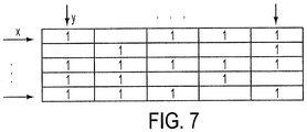
- the algorithm only uses one counting variable to store all the points in the point cloud and then uses the same loop to fill the height map (I). Once the matrix (I) is created, the algorithm needs to fill the spaces that are blank, which represent missed points (points not scanned by the LIDAR). To fill that empty space the algorithm interpolates each column and row, as illustrated in FIG. 7 . Each empty space, or pixel is estimated by interpolation across z and along y.
- Image enhancement filtering detects small variations in the terrain. Small variations in the terrain may be correlated with rocks, weeds, small man-made structures or objects, etc.
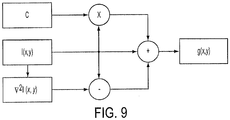
- the HLZ algorithm uses a high-boost-Laplacian sharpening filter in the frequency domain, as follows:
- F(u,v) is the original image (I(x,y)) in the frequency domain.
- the filtering of a signal is achieved by using convolution. Convolution of discrete signals, however, is time-consuming. In the frequency domain, however, the filtered signal may be obtained by multiplying the image by the transfer function or filter response, as shown in the block diagram presented in FIG. 8 .
- Real-time signal processing by the present invention uses a fast Fourier transform (FFT) to filter data in multiple dimensions.
- FFT fast Fourier transform
- the advantage of FFT is that it may be implemented in FPGA acceleration cards, DSP-16 real-time, or other type of DSP cards, which are capable of operating above real-time rates.
- the Laplacian filter is combined with a high-boost filter.
- the high-boost filter is used to emphasize high frequency components in the image. A high frequency component helps differentiate objects and changes in the terrain due to discontinuities.
- the high-boost (hb) filter When A is equal to one, the high-boost (hb) filter is reduced to a normal high pass (hp) filter. If A is greater than 1, the contribution of the image is dominant. If A is less than one, however, the contribution of the filter is dominant.
- the high-boost filter is used to un-sharpen an image.
- the algorithm takes advantage of the calculations done by image enhancement unit 52.
- the gradient of the height map is used for segmenting the image by segmentation unit 57, since gradients are used for detecting the edges of different objects in the image. Then, those edges are translated into a boundary of each object in the image. Once the boundary of each object is determined, the algorithm checks the distribution of points inside each boundary. If inside each boundary there are points larger than a predetermined height, the algorithm classifies the object inside the boundary region as a vertical obstruction (VO).
- FIG. 10 shows a block diagram for detecting a vertical obstruction.
- the present invention also takes advantage of previous computations for improving efficiency of the algorithm. Re-using calculations helps to minimize the processing time of the HLZ algorithm.
- gradients are used for implementing a filter bank, which are also used to determine the edges of the enhanced image. Finding the edges in the enhanced image has the advantage that small features in the scene may be detected.
- edges are determined (by Eq. 13), the algorithm proceeds to link the edges to perform boundary detection.
- the properties used for determining similar edge points are given by the strength of the response of the gradient operator and the direction of the gradient vector.
- a point in a predefined neighborhood is linked to the pixel at (x,y), if both magnitude and direction criteria are satisfied as presented by Equations 15 and 16.
- the algorithm proceeds to generate vectors for representing the edges of each object. Euclidian distance is used to determine those pixels that belong to one object, as follows: E x y ⁇ O k x y if the distance is close , otherwise if the distance is close, otherwise the pixel is part of another class.
- E(x,y) is the edge's pixel and O k represents the object where the edge pixel belongs.
- edges may be used to find the boundaries of each detected object by linking them into vectors.
- this approach produces object contours.
- threshold parameters are used to filter regions that meet aircraft landing criteria.
- the values for the threshold parameters used by the present invention are RO th (roughness), VO th (vertical obstruction distance), and S th (ground slope). These threshold values are used in landing zone detection module 18 as criteria for decision boxes RO th (roughness) 22, VO th (vertical obstruction distance) 24, and S th (ground slope) 26, respectively.
- landing zone detection module 18 provides possible landing zones to the aircraft.
- Values such as slopes between 7-15° for most aircraft, 10 feet clearance for vertical obstructions, and roughness values of 0.44 meter or greater are examples of typical threshold values.
- Each aircraft has different specifications and, therefore, the parameters are adjusted based on the required landing zone (RLZ) values, which are provided as metadata by parameters module 15.
- RZ landing zone
- the aforementioned parameter values provide opportunities for safe landing, but as in automobile GPS devices, there are other factors that help segregate good landing zones from great landing zones.
- Parameters such as weather requirements (e.g. wind speed and humidity) may affect landing zone selections, as well as the nearest landing zone along a predefined flight path, and the line of sight (LOS) cone to the landing zone of interest. All these parameters are optional, but may be used to define the best landing zone, the best approach for the landing zone, and the best position to center the aircraft within the landing zone.
- the best landing zone is determined by landing zone filtering module 20, which outputs a safe landing zone by safe landing zone unit 44.
- landing zone filtering module 20 compares the selected landing zone area (unit 32) against a desirable area based on weather conditions. Decision box 40 determines whether the selected landing area is greater than or equal to the desirable landing area. If it is, then safe landing zone unit 44 may provide a safe landing flag for the selected landing zone area. Next, the VO distance (unit 38) and the selected landing zone center (unit 34) are compared against a desired distance by decision box 42. If decision box 42 determines that the VO distance is greater than or equal to the desired distance, then a flag is provided to the safe landing zone unit 44. Finally, LOS unit 36 provides the LOS cone parameters to the safe landing zone unit 44.
- method 10 verifies if there is a GPS and GIS available. If either one of these systems or metadata is available, the method, by way of classification module 14, classifies the point cloud dataset as including land or water data points. If GIS data is not available, however, the method may fail by classifying water regions as landing zones.
- the method 10 generates a height map (HM) based on the point cloud dataset. After the HM is available, the method enhances the HM using filter unit 52 by improving the details of features and/or edges.
- the filtered HM is preferred to as an enhanced height map (EHM).
- the method uses the HM to calculate the slope of the terrain by way of slope unit 55.
- V unit 58 determines any VO by using the segments resulting from the gradient calculation.
- Gradient unit 54 determines discontinuities across the HM and associates the discontinuities with vertical obstructions.
- Every map (HM, EHM, slope and VO) may be of the same size.
- the method 10 generates a possible landing zone map (PLZM) and sets every pixel equal to zero that corresponds to a possible landing zone.
- PZM possible landing zone map
- method 10 creates a moving mask of the same size and shape of the required landing zone. This mask is used to store the pixel values of each map and then to compare every map in the same location.
- the method computes the roughness of the terrain and makes comparisons of each parameter with pre-defined thresholds. This generates possible landing zones.
- the possible landing zones are preferably of the same size or larger than the required landing area.
- the method 10 proceeds to filter the landing zones based on optional parameters by way of filtering module 20.
- the process ranks the possible landing zones from low risk to high risk.
- the method ranks the landing zones by aerial size in descending order.
- the method determines the center of each landing zone and determines the distances between each landing zone and VO.
- the method determines the LOS and ranks landing zones with low and high visibility as a function of height. This essentially weighs each landing zone by the shape of a cone generated from the LOS.
- the landing zone filtering module 20 executes landing zone filtering of all landing zones detected by landing zone detection module 18.
- the landing zone filtering module combines the required area for an aircraft landing, the distance between the center of the landing zone and the vertical obstructions (VOs), and the line of sight (LOS) from the aircraft.
- VOs vertical obstructions
- LOS line of sight
- the filtering module uses an imaginary cone which is located in the center of each landing zone to determine a vertical obstruction in a possible landing path.
- the VOs are all objects that represent a risk for landing in a speciic area.
- the LOS is based on an imaginary line that drives the pilot through the center of the landing zone. From another point-of-view, the LOS is an imaginary line from the center of the landing zone through the helicopter.
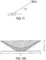
- FIG. 11 shows the LOS as defined by the present invention.
- the landing path depends on the specifications of the aircraft (size, weight, hardware, mission, etc.). If the helicopter flies around the landing zone, designated by H, an imaginary cone or funnel in 3D space is formed.
- FIG. 12A shows an imaginary funnel (cone) in 3D space where the lower radius of the funnel is based on the helicopter landing area and the upper radius is based on the LOS angle or landing path required for a safe landing.
- the height of the funnel is based on the helicopter height at a specific distance from the landing zone.
- the funnel method is used to determine the VO surrounding the landing area. Recall, the radius at the base of the funnel is based on the required landing area and the VOs are then objects inside the funnel.
- FIG. 12B presents an example of the funnel being close to a VO, such as a building positioned at the left side of the funnel.
- the building is not considered a risk, because it is outside of funnel.
- the LOS angle is between 30-45 degrees, depending on the aircraft specification and mission.
- the funnel in FIG. 12B shows a clear area for safe landing.
- FIG. 12C shows a second example in which two objects are inside the funnel. Both objects are buildings obstructing a landing zone. If there are objects inside the funnel area, the algorithm ranks the landing area as a risky one. In ranking the landing zones, the algorithm considers the distance of each object from the center of the funnel. In case that all possible landing areas have obstructions, the algorithm recommends the area where the obstruction is farther from the center of the cone.
- the funnel method of the present invention is not limited to a single position.
- the funnel may be oriented in different angles to verify if the pilot is able to land quickly into a specific area.
- the LOS is projected through the center of the funnel, which is the path that the pilot should follow for a safe landing.
- FIG. 12D the funnel is oriented using the LOS concept.
- the funnel is important in real-time applications where the LIDAR is attached to the aircraft and the imaginary line from the helicopter through the landing zone is the route that the pilot needs to follow.
- the present invention advantageously speeds up the algorithm by projecting the detected VOs into a 2D circle, which has a radius equal to the upper radius of the funnel. Funnels with VOs close to the center of the funnel are considered landing zones of high risk. Landing zones with VOs far from the landing area are considered safe. Perfect landing zones are those landing zones without VOs inside the funnel.
- the algorithm of the present invention uses the 2D circle projection to estimate the optimum landing path. Having obstructions close to the landing zone represents a risk if the landing path is in a specific direction. But, other landing paths may be considered.
- FIG. 13 presents a predicted optimum landing path.
- the figure illustrates a cone from a top-view where the small circle at the center (with a small "H") represents the landing zone area.
- the VOs represent obstacles, i.e., buildings.
- An imaginary vector rotates counter-clockwise to determine the distance between each obstruction and the center of the landing area. Once those distances are determined, the imaginary vector is moved into a position where the obstacles are far away. Following the example shown in FIG. 13 , the vector is moved into a position where the distances d 1 and d 2 are a maximum. This position is the optimum direction for landing.
- FIG. 14 shows an example of how an optimum landing path is determined.
- the algorithm considers all objects inside the funnel and determines the distances and upper boundary of the funnel.
- FIG. 14 is a top view of the funnel where each line represents the position of the rotational vector, and the points represents the objects inside the funnel.
- the end of each rotational vector around the circle is represented by P i (x,y) which is used to determine the distance of a detected object inside the funnel and the boundary of the circle.
- the optimum landing path is determined by selecting the point around the circle with the maximum distance and its projection through the center of the circle.
- PSEUDO code is an example of how a decision for an optimum landing path may be made by the present invention:
- the method 10 overlays the determined safe landing zones in white and marks the center of each landing zone with a pink "H”.
- method 10 ingests any type of LADAR point cloud data. Whether it is a full motion LADAR system or a static collection of video frames, the method offers a safe landing zone within a short period of time. For real time scenarios, the operator (pilot) may use the present invention to find safe landing zones when a full motion video LADAR is used. The method 10 generates much smaller datasets, frame to frame, which enables a safe landing zone to be generated and displayed in real-time.
- the SLAD algorithm is the only algorithm that determines safe landing zones, but only when enough data of an entire region has been collected by stereo pair cameras. Since the data is only minutes old, an assumption is made that the ground terrain does not change much during that time period. This enables the pilot to make decisions during landing maneuvers.
- the SLAD algorithm allows the pilot to find landing zones based on roughness and slope of the stereo pair cameras, but uses a very different algorithm to do so.
- the algorithm uses set circles of regions that pass roughness and slope tests. Each circle starts growing and stops when a possible obstruction is crossed. Next, the algorithm selects circles with ratios equal to or larger than the required landing area.
- This concept of growing circles is computationally expensive, and limits the real-time requirements that are necessary when changes in a scene occur in seconds, not minutes. Since the present invention uses a moving window mask to find regions that meet the aircraft requirements, the present invention processes video rate point cloud data for real-time situational awareness.
- the landing zone ranking order changes based on moving objects in the scene on millisecond time scales. This timescale is essential for real-time situational awareness.
- Feature extraction by other active sensing applications such as bathymetry for semi-submersibles, subsurface sea mines, etc. require similar concepts as method 100.
- the method may generate a map of spherical objects within a video rate point cloud dataset in real-time. Real time feature extraction is possible when video rate LADAR systems are used.
Landscapes
- Engineering & Computer Science (AREA)
- Physics & Mathematics (AREA)
- General Physics & Mathematics (AREA)
- Radar, Positioning & Navigation (AREA)
- Remote Sensing (AREA)
- Computer Networks & Wireless Communication (AREA)
- Electromagnetism (AREA)
- Aviation & Aerospace Engineering (AREA)
- Automation & Control Theory (AREA)
- Processing Or Creating Images (AREA)
- Optical Radar Systems And Details Thereof (AREA)
- Traffic Control Systems (AREA)
Claims (13)
- Verfahren zum Auswählen einer sicheren Landezone für ein Flugzeug, vorzugsweise einen Hubschrauber, die folgenden Schritte umfassend:Empfangen, von einem LADAR oder LIDAR System (104), 4 dimensionale, 4D, Punktwolkendaten als sequentielle Bildrahmen;Referenzieren, durch einen Prozessor (108), jeden Bildrahmen auf geographische Koordinaten;dadurch gekennzeichnet, dass das Verfahren weiterhin die Schritte aufweist:Klassifizieren einer Region in jedem Bildrahmen entweder als Landregion oder als Wasserregion basierend auf den geographischen Informationssystemmetadaten verbunden mit den geographischen Koordinaten bezüglich jedem Bildrahmen;Auswählen, durch den Prozessor (108), einer Region, die in jedem Bildrahmen als Landregion klassifiziert worden ist, basierend auf der Klassifikation einer Region als Land;Bilden einer Höhenkarte (51) der ausgewählten Landregion, wobei die Höhenkarte Pixelwerte der Höhe über der Landregion beinhaltet,Erfassen der Kanten eines Objekts in der Höhenkarte, wobei die Kanten Grenzen des Objekts bilden;Finden einer maximalen Höhe innerhalb der Grenzen des Objekts;Klassifizieren des Objektes als vertikales Hindernis, VO, (58), wenn die maximale Höhe größer ist, als ein vorbestimmter VO Schwellwert;basierend auf dem VO, Auswählen einer möglichen Landezone für das Flugzeug durch den Prozessor; undBestimmen durch den Prozessor (108), dass die mögliche Landezone eine sichere Landezone für das Flugzeug ist.
- Verfahren nach Anspruch 1, wobei Referenzieren jedes Bildrahmens umfasst Verwenden eines globalen Positionierungssystems, GPS, (102), oder eines Trägheitssystems (106), um die 4D Punktwolkendaten in x, y, z geographische Koordinaten als Funktion der Zeit, t, umzuwandeln.
- Verfahren nach Anspruch 1, wobei das Erfassen der Kanten die Schritte umfasst:Anwenden einer schnelle Fourier-Transformation, FFT, über die Höhenkarte zum Erhalt der Höhe in einer Frequenzdomäne,Berechnen von Gradienten der Höhe in der Frequenzdomäne, wobei die Gradienten die Kanten definieren, undRepräsentieren der Kanten als "Einsen" und andere Teile der Höhenkarte als "Nullen".
- Verfahren nach Anspruch 3 außerdem die Schritte enthaltend:Bilden einer Neigungskarte über der Höhenkarte, in der eine Neigung eines Pixels von Interesse auf 4 Nachbarpixel, die das interessierende Pixel umgeben, basiert, undBestimmen der Rauigkeit über der Höhenkarte, wobei die Rauigkeit eine Standardabweichung der Höhenwerte größer als 0,3 enthält.
- Verfahren nach Anspruch 1, ferner umfassend:Bilden einer VO Karte, die vertikale Hindernisse in der Landregion darstellt,Bilden einer Neigungskarte, die die Neigung von Datenpunkten in der Landregion darstellt; undwobei das Auswählen einer möglichen Landezone für das Flugzeug die Schritte aufweist:Bewegen einer Maske, definiert durch einen vorgegebenen Bereich für die Landung, über die Landregion, zum Auswählen der möglichen Landezone für das Flugzeug,wobei die sichere Landezone umfasst(a) VOs, die geringer sind, als eine vorgegebene Höhe innerhalb der bewegenden Maske, und(b) Neigungen, die geringer sind als eine Standardabweichung der Höhe von weniger als 0,3 innerhalb der bewegenden Maske.
- Verfahren nach Anspruch 5 außerdem die Schritte enthaltend:Berechnen, mittels des Prozessors, eines Trichters ausgehend von einem Zentrum einer möglichen Landezone, wobei der Trichter durch eine Sichtlinie, LOS, definiert ist, projiziert vom Flugzeug zum Zentrum der möglichen Landezone, und eine Höhe besitzt, gebildet von der Höhenlage des Flugzeugs über der möglichen Landezone, undKlassifizieren, mittels des Prozessors, der möglichen Landezone als eine sichere Landezone, wenn ein VO außerhalb des Trichters ist.
- Verfahren nach Anspruch 1, wobei das Bestimmen, durch den Prozessor (108), dass die mögliche Landezone eine sichere Landezone für das Flugzeug ist, durchgeführt wird während eine Zeitspanne, die ausreicht, um eine Landevisualisierung in Echtzeit auszuführen.
- Ein System zum Bestimmen einer sicheren Landezone für ein Flugzeug, vorzugsweise für einen Helikopter, umfassend:einen Prozessor (108) zum Empfangen von 4 dimensionalen, 4D, Punktwolkendaten von einem Sensor, umfassend einen LADAR oder LIDAR Sensor (104), wobei die Daten durch aufeinanderfolgende Bildrahmen definiert sind,wobei der Prozessor (108) konfiguriert ist:jeden Bildrahmen in geographische kartesische Koordinaten (x, y, z) umzuwandeln, wobei x und y eine Funktion eines Abtastwinkels des Sensors sind und z die Höhe ist,dadurch gekennzeichnet, dass der Prozessor weiter konfiguriert ist:Klassifizieren einer Region in jedem Bildrahmen entweder als Landregion oder als Wasserregion, basierend auf den geographischen Informationssystemmetadaten verbunden mit den geographischen Koordinaten bezüglich jedes Bildrahmens,Auswählen einer Region, die als Landregion in jedem Bildrahmen klassifiziert wurde, basierend auf der Klassifikation einer Region als Land,Bilden einer Höhenkarte (51) der ausgewählten Landregion, wobei die Höhenkarte Pixelwerte für die Höhe über der Landregion enthält,Segmentieren der Höhenkarte in Grenzen eines jeweiligen Objektes in dem Bildrahmen, und Detektieren von Kanten des Objekts in der Höhenkarte, wobei die Kanten Grenzen des betreffenden Objekts bilden;Finden einer maximalen Höhe innerhalb der Grenzen des betreffenden Objekts,Klassifizieren des Objektes als ein vertikales Hindernis, VO, um eine VO Karte (58) zu erzeugen, wenn die maximale Höhe größer ist, als ein vorbestimmter VO Grenzwert,mathematisches Bewegen einer Maske über die VO Karte, wobei die Maske auf einer vorgegebenen Landezone basiert, die für das Luftfahrzeug erforderlich ist;wobei das System außerdem umfasst:ein Visualisierungssystem (110) zum Anzeigen der sicheren Landezone über der VO Karte zum Landen des Flugzeugs.
- System nach Anspruch 8, wobei der Prozessor (108) wie folgt konfiguriert ist:Berechnen eines Trichters, der sich von einer Mitte einer möglichen Landezone erstreckt, wobei der Trichter durch eine Sichtlinie, LOS, definiert ist, projiziert von dem Flugzeug zu der Mitte der möglichen Landezone und eine Höhe aufweist, die durch eine Höhenlage des Flugzeugs über der Landezone gebildet ist;Klassifizieren der möglichen Landezone als sichere Landezone, wenn ein VO außerhalb des Trichters ist.
- Ein Prozessor (108) zum Berechnen einer sicheren Landezone für ein Flugzeug, wobei der Prozessor die folgenden Schritte ausführt:(a) Empfangen von 4 dimensionalen, 4D, Punktwolkendaten von einem Sensor, umfassend einen LADAR oder LIDAR Sensor (104), wobei die Daten durch aufeinanderfolgende Bildrahmen definiert sind, und Umwandeln der 4D Punktwolkendaten in geographischen kartesische Koordinaten einer Region;gekennzeichnet dadurch, dass der Prozessor außerdem die Schritte durchführt:(b) Klassifizieren der Region in jedem Bildrahmen als entweder Landregion oder Wasserregion, basierend auf geographischen Informationssystemmetadaten verbunden mit den geographischen Koordinaten bezüglich jedes Bildrahmens,(c) Auswählen einer Region, die als Landregion in jedem Bildrahmen klassifiziert wurde, basierend auf der Klassifikation einer Region als Land,(d) Bilden einer Höhenkarte (51) der ausgewählten Landregion, wobei die Höhenkarte Pixelwerte für die Höhe über der Landregion enthält,(e) Detektieren von Kanten eines Objekts in der Höhenkarte, wobei die Kanten Grenzen des betreffenden Objekts bilden;(f) Segmentieren der Höhenkarte um Grenzen eines Objektes in der Region zu bilden;(g) Bestimmen einer maximalen Höhe innerhalb der Grenzen des Objektes, und, wenn die maximale Höhe größer ist, als eine vorgegebene Höhe, Klassifizieren des Objektes als ein vertikales Hindernis, VO, um eine VO Karte (58) zu erzeugen,(h) Markieren einer Gegend innerhalb der VO Karte als mögliche Landezone für das Flugzeug;(i) Berechnen eines Trichters, der sich von einer Mitte einer möglichen Landezone erstreckt, wobei der Trichter durch eine Sichtlinie, LOS, definiert ist, projiziert von dem Flugzeug zu der Mitte der Landezone und eine Höhe aufweist, die durch eine Höhenlage des Flugzeugs über der Landezone gebildet wird;(j) Klassifizieren der möglichen Landezone als sichere Landezone, wenn ein VO außerhalb des Trichters ist; und(k) Anzeigen der sicheren Landezone über der der VO Karte, zum Landen des Flugzeugs.
- Prozessor nach Anspruch 10, der folgende zusätzlichen Schritte ausführt:(1) Bestimmen, ob die 4D Punktwolkendaten von Land oder Wasser betreffen; und(m) Verhindern der Ausführung der Schritte (c) bis (k), wenn die 4D Punktwolkendaten Wasser betreffen.
- Prozessor nach Anspruch 10, umfassend:einen ersten Prozessor zum Ausführen von Schritt (a) undeinen zweiten Prozessor zum Ausführen mindestens von Schritt (b),wobei der erste und der zweite Prozessor derart konfiguriert sind, die Schritte parallel auszuführen.
- Prozessor nach Anspruch 10, der folgende zusätzlichen Schritte ausführt:Bereitstellen einer VO Karte der Landezone an ein Visualisierungssystem während einer Zeitspanne, die für die Landung des Flugzeugs in Echtzeit ausreicht.
Applications Claiming Priority (2)
| Application Number | Priority Date | Filing Date | Title |
|---|---|---|---|
| US13/454,158 US8600589B2 (en) | 2012-04-24 | 2012-04-24 | Point cloud visualization of acceptable helicopter landing zones based on 4D LIDAR |
| PCT/US2013/035063 WO2013162839A1 (en) | 2012-04-24 | 2013-04-03 | Point cloud visualization of acceptable helicopter landing zones based on 4d lidar |
Publications (2)
| Publication Number | Publication Date |
|---|---|
| EP2850455A1 EP2850455A1 (de) | 2015-03-25 |
| EP2850455B1 true EP2850455B1 (de) | 2017-02-08 |
Family
ID=48093127
Family Applications (1)
| Application Number | Title | Priority Date | Filing Date |
|---|---|---|---|
| EP13716143.6A Not-in-force EP2850455B1 (de) | 2012-04-24 | 2013-04-03 | Punktwolkenvisualisierung von akzeptablen hubschrauberlandebereichen auf basis von 4d-lidar |
Country Status (7)
| Country | Link |
|---|---|
| US (1) | US8600589B2 (de) |
| EP (1) | EP2850455B1 (de) |
| JP (1) | JP2015522458A (de) |
| CA (1) | CA2870677A1 (de) |
| IL (1) | IL235113B (de) |
| MX (1) | MX2014012901A (de) |
| WO (1) | WO2013162839A1 (de) |
Families Citing this family (122)
| Publication number | Priority date | Publication date | Assignee | Title |
|---|---|---|---|---|
| EP2562309B1 (de) * | 2011-08-22 | 2014-04-02 | Joseph Vögele AG | Straßenfertiger mit Messvorrichtung |
| US8600589B2 (en) * | 2012-04-24 | 2013-12-03 | Exelis, Inc. | Point cloud visualization of acceptable helicopter landing zones based on 4D LIDAR |
| US9836871B2 (en) * | 2012-08-02 | 2017-12-05 | Here Global B.V. | Three-dimentional plane panorama creation through hough-based line detection |
| US9568919B2 (en) * | 2012-10-24 | 2017-02-14 | Aurora Flight Sciences Corporation | System and methods for automatically landing aircraft |
| US9709990B2 (en) * | 2012-12-21 | 2017-07-18 | Toyota Jidosha Kabushiki Kaisha | Autonomous navigation through obstacles |
| US9412040B2 (en) * | 2013-12-04 | 2016-08-09 | Mitsubishi Electric Research Laboratories, Inc. | Method for extracting planes from 3D point cloud sensor data |
| US9177481B2 (en) * | 2013-12-13 | 2015-11-03 | Sikorsky Aircraft Corporation | Semantics based safe landing area detection for an unmanned vehicle |
| EP2894600B1 (de) * | 2014-01-14 | 2018-03-14 | HENSOLDT Sensors GmbH | Verfahren zur Verarbeitung 3D-Sensordaten zur Bereitstellung von Geländesegmentierung |
| FR3018383B1 (fr) * | 2014-03-07 | 2017-09-08 | Airbus Operations Sas | Procede et dispositif de determination de parametres de navigation d'un aeronef lors d'une phase d'atterrissage. |
| US9688403B2 (en) | 2014-05-20 | 2017-06-27 | Infatics, Inc. | Method for adaptive mission execution on an unmanned aerial vehicle |
| WO2015200086A1 (en) * | 2014-06-23 | 2015-12-30 | Sikorsky Aircraft Corporation | Cooperative safe landing area determination |
| US9617011B2 (en) | 2014-06-24 | 2017-04-11 | Sikorsky Aircraft Corporation | Probabilistic safe landing area determination |
| US9382016B2 (en) | 2014-06-24 | 2016-07-05 | Sikorsky Aircraft Corporation | Aircraft landing monitor |
| US10915673B2 (en) * | 2014-07-01 | 2021-02-09 | Scanifly, LLC | Device, method, apparatus, and computer-readable medium for solar site assessment |
| US20160027313A1 (en) * | 2014-07-22 | 2016-01-28 | Sikorsky Aircraft Corporation | Environmentally-aware landing zone classification |
| WO2016048743A1 (en) | 2014-09-22 | 2016-03-31 | Sikorsky Aircraft Corporation | Context-based autonomous perception |
| WO2016109000A2 (en) * | 2014-10-20 | 2016-07-07 | Sikorsky Aircraft Corporation | Optimal safe landing area determination |
| US9540118B2 (en) | 2014-11-10 | 2017-01-10 | Federal Express Corporation | Risk assessment framework |
| US10163255B2 (en) * | 2015-01-07 | 2018-12-25 | Geopogo, Inc. | Three-dimensional geospatial visualization |
| US20160252351A1 (en) * | 2015-02-27 | 2016-09-01 | Ge Aviation Systems Llc | System and methods for providing situational awareness information for a relative navigation system |
| US20160335901A1 (en) * | 2015-04-07 | 2016-11-17 | Near Earth Autonomy, Inc. | Control of autonomous rotorcraft in limited communication environments |
| US10818084B2 (en) * | 2015-04-07 | 2020-10-27 | Geopogo, Inc. | Dynamically customized three dimensional geospatial visualization |
| US10029804B1 (en) * | 2015-05-14 | 2018-07-24 | Near Earth Autonomy, Inc. | On-board, computerized landing zone evaluation system for aircraft |
| US10698111B2 (en) * | 2015-05-15 | 2020-06-30 | Sikorsky Aircraft Corporation | Adaptive point cloud window selection |
| US9896204B1 (en) | 2015-06-15 | 2018-02-20 | Amazon Technologies, Inc. | Instructing unmanned aerial vehicles to land |
| US10061328B2 (en) | 2015-08-12 | 2018-08-28 | Qualcomm Incorporated | Autonomous landing and control |
| CN105223583B (zh) * | 2015-09-10 | 2017-06-13 | 清华大学 | 一种基于三维激光雷达的目标车辆航向角计算方法 |
| US10557939B2 (en) | 2015-10-19 | 2020-02-11 | Luminar Technologies, Inc. | Lidar system with improved signal-to-noise ratio in the presence of solar background noise |
| CN108369274B (zh) | 2015-11-05 | 2022-09-13 | 路明亮有限责任公司 | 用于高分辨率深度映射的具有经改进扫描速度的激光雷达系统 |
| US10591600B2 (en) | 2015-11-30 | 2020-03-17 | Luminar Technologies, Inc. | Lidar system with distributed laser and multiple sensor heads |
| US9947232B2 (en) * | 2015-12-08 | 2018-04-17 | Honeywell International Inc. | Methods and apparatus for identifying terrain suitable for aircraft landing |
| US10402696B2 (en) * | 2016-01-04 | 2019-09-03 | Texas Instruments Incorporated | Scene obstruction detection using high pass filters |
| US12399279B1 (en) | 2016-02-15 | 2025-08-26 | Red Creamery Llc | Enhanced hybrid LIDAR with high-speed scanning |
| US12399278B1 (en) | 2016-02-15 | 2025-08-26 | Red Creamery Llc | Hybrid LIDAR with optically enhanced scanned laser |
| US11556000B1 (en) | 2019-08-22 | 2023-01-17 | Red Creamery Llc | Distally-actuated scanning mirror |
| US12123950B2 (en) | 2016-02-15 | 2024-10-22 | Red Creamery, LLC | Hybrid LADAR with co-planar scanning and imaging field-of-view |
| US10611495B2 (en) * | 2016-04-08 | 2020-04-07 | Sikorsky Aircraft Corporation | Sea state estimation |
| CN106094841B (zh) * | 2016-05-31 | 2018-11-23 | 北京小米移动软件有限公司 | 飞行设备降落方法及装置 |
| US10390003B1 (en) | 2016-08-29 | 2019-08-20 | Perceptln Shenzhen Limited | Visual-inertial positional awareness for autonomous and non-autonomous device |
| US10571926B1 (en) | 2016-08-29 | 2020-02-25 | Trifo, Inc. | Autonomous platform guidance systems with auxiliary sensors and obstacle avoidance |
| US10032276B1 (en) | 2016-08-29 | 2018-07-24 | PerceptIn, Inc. | Visual-inertial positional awareness for autonomous and non-autonomous device |
| US10366508B1 (en) | 2016-08-29 | 2019-07-30 | Perceptin Shenzhen Limited | Visual-inertial positional awareness for autonomous and non-autonomous device |
| US10453213B2 (en) * | 2016-08-29 | 2019-10-22 | Trifo, Inc. | Mapping optimization in autonomous and non-autonomous platforms |
| US10395117B1 (en) | 2016-08-29 | 2019-08-27 | Trifo, Inc. | Visual-inertial positional awareness for autonomous and non-autonomous tracking |
| US10402663B1 (en) * | 2016-08-29 | 2019-09-03 | Trifo, Inc. | Visual-inertial positional awareness for autonomous and non-autonomous mapping |
| US11314262B2 (en) | 2016-08-29 | 2022-04-26 | Trifo, Inc. | Autonomous platform guidance systems with task planning and obstacle avoidance |
| US10410328B1 (en) | 2016-08-29 | 2019-09-10 | Perceptin Shenzhen Limited | Visual-inertial positional awareness for autonomous and non-autonomous device |
| US10043076B1 (en) | 2016-08-29 | 2018-08-07 | PerceptIn, Inc. | Visual-inertial positional awareness for autonomous and non-autonomous tracking |
| US10162362B2 (en) | 2016-08-29 | 2018-12-25 | PerceptIn, Inc. | Fault tolerance to provide robust tracking for autonomous positional awareness |
| US10571925B1 (en) | 2016-08-29 | 2020-02-25 | Trifo, Inc. | Autonomous platform guidance systems with auxiliary sensors and task planning |
| US10482776B2 (en) | 2016-09-26 | 2019-11-19 | Sikorsky Aircraft Corporation | Landing zone evaluation and rating sharing among multiple users |
| US10353388B2 (en) | 2016-10-17 | 2019-07-16 | X Development Llc | Drop-off location planning for delivery vehicle |
| US11292602B2 (en) | 2016-11-04 | 2022-04-05 | Sony Corporation | Circuit, base station, method, and recording medium |
| DE102016224530B3 (de) * | 2016-12-08 | 2018-01-18 | Man Truck & Bus Ag | Verfahren zur Bodenoberflächenschätzung |
| US12387429B2 (en) | 2017-02-02 | 2025-08-12 | DroneDeploy, Inc. | System and methods for improved aerial mapping with aerial vehicles |
| WO2018144929A1 (en) * | 2017-02-02 | 2018-08-09 | Infatics, Inc. (DBA DroneDeploy) | System and methods for improved aerial mapping with aerial vehicles |
| CN106997049B (zh) * | 2017-03-14 | 2020-07-03 | 奇瑞汽车股份有限公司 | 一种基于激光点云数据的检测障碍物的方法和装置 |
| US9810775B1 (en) | 2017-03-16 | 2017-11-07 | Luminar Technologies, Inc. | Q-switched laser for LIDAR system |
| US9905992B1 (en) | 2017-03-16 | 2018-02-27 | Luminar Technologies, Inc. | Self-Raman laser for lidar system |
| US9810786B1 (en) | 2017-03-16 | 2017-11-07 | Luminar Technologies, Inc. | Optical parametric oscillator for lidar system |
| US9869754B1 (en) | 2017-03-22 | 2018-01-16 | Luminar Technologies, Inc. | Scan patterns for lidar systems |
| US10545240B2 (en) | 2017-03-28 | 2020-01-28 | Luminar Technologies, Inc. | LIDAR transmitter and detector system using pulse encoding to reduce range ambiguity |
| US10007001B1 (en) | 2017-03-28 | 2018-06-26 | Luminar Technologies, Inc. | Active short-wave infrared four-dimensional camera |
| JP6564803B2 (ja) * | 2017-03-28 | 2019-08-21 | 株式会社Subaru | 無人航空機の飛行制御装置、無人航空機の飛行制御方法、及び無人航空機の飛行制御プログラム |
| US10593042B1 (en) * | 2017-04-11 | 2020-03-17 | Zoox, Inc. | Perspective conversion for multi-dimensional data analysis |
| US10509947B1 (en) * | 2017-04-11 | 2019-12-17 | Zoox, Inc. | Converting multi-dimensional data for image analysis |
| US10663590B2 (en) * | 2017-05-01 | 2020-05-26 | Symbol Technologies, Llc | Device and method for merging lidar data |
| US10444761B2 (en) | 2017-06-14 | 2019-10-15 | Trifo, Inc. | Monocular modes for autonomous platform guidance systems with auxiliary sensors |
| US10496104B1 (en) | 2017-07-05 | 2019-12-03 | Perceptin Shenzhen Limited | Positional awareness with quadocular sensor in autonomous platforms |
| US10393528B2 (en) | 2017-08-02 | 2019-08-27 | Wing Aviation Llc | Systems and methods for navigation path determination for unmanned vehicles |
| US10545500B2 (en) | 2017-08-02 | 2020-01-28 | Wing Aviation Llc | Model for determining drop-off spot at delivery location |
| US10621448B2 (en) | 2017-08-02 | 2020-04-14 | Wing Aviation Llc | Systems and methods for determining path confidence for unmanned vehicles |
| US10546503B2 (en) * | 2017-08-22 | 2020-01-28 | Honeywell International Inc. | Method and system for real-time validation of an operational flight path for an aircraft |
| US10402646B2 (en) * | 2017-09-21 | 2019-09-03 | Amazon Technologies, Inc. | Object detection and avoidance for aerial vehicles |
| JP7109174B2 (ja) * | 2017-10-03 | 2022-07-29 | 株式会社トプコン | 経路選定装置、無人航空機、データ処理装置、経路選定処理方法および経路選定処理用プログラム |
| US10787258B2 (en) * | 2017-11-11 | 2020-09-29 | The Boeing Company | Portable unmanned aerial vehicle approach and departure zone protection platform |
| KR102039797B1 (ko) * | 2017-11-13 | 2019-11-01 | 울산대학교 산학협력단 | 드론의 착륙 유도 장치 및 방법 |
| KR102045362B1 (ko) * | 2017-12-01 | 2019-11-15 | 에어버스 헬리콥터스 | 회전익기의 조종 보조 장치, 연관된 디스플레이, 및 대응하는 조종 보조 방법 |
| WO2019119184A1 (zh) * | 2017-12-18 | 2019-06-27 | 深圳市大疆创新科技有限公司 | 地形预测方法、设备、系统和无人机 |
| US10577101B2 (en) | 2017-12-21 | 2020-03-03 | Autel Robotics Co., Ltd. | Water surface detection method and apparatus, unmanned aerial vehicle landing method and apparatus and unmanned aerial vehicle |
| CN108846084B (zh) * | 2018-06-11 | 2021-06-29 | 成都山河空间信息技术有限公司 | 一种实景地图的生成系统和方法 |
| CN108804675B (zh) * | 2018-06-11 | 2021-06-22 | 成都山河空间信息技术有限公司 | 基于多源空间数据的无人机移动空间信息管理系统和方法 |
| CN109144097B (zh) * | 2018-08-15 | 2021-04-06 | 广州极飞科技有限公司 | 障碍物或地面识别及飞行控制方法、装置、设备及介质 |
| US11428817B2 (en) * | 2018-10-11 | 2022-08-30 | Baidu Usa Llc | Automatic LIDAR calibration based on cross validation for autonomous driving |
| US11841437B2 (en) | 2018-10-12 | 2023-12-12 | Baidu Usa Llc | Automatic lidar calibration based on pre-collected static reflection map for autonomous driving |
| WO2020103049A1 (zh) * | 2018-11-21 | 2020-05-28 | 深圳市大疆创新科技有限公司 | 旋转微波雷达的地形预测方法、装置、系统和无人机 |
| CN109739256B (zh) * | 2018-12-20 | 2022-04-19 | 深圳市道通智能航空技术股份有限公司 | 一种无人机降落避障方法、装置及无人机 |
| CN109343572B (zh) * | 2018-12-20 | 2021-07-30 | 深圳市道通智能航空技术股份有限公司 | 一种无人机自主降落方法、装置及无人机 |
| US11774983B1 (en) | 2019-01-02 | 2023-10-03 | Trifo, Inc. | Autonomous platform guidance systems with unknown environment mapping |
| EP4517710A3 (de) | 2019-03-13 | 2025-05-21 | Federal Express Corporation | Minderung des betriebsrisikos in flugzeugen |
| CN111724472B (zh) * | 2019-03-19 | 2024-07-02 | 北京四维图新科技股份有限公司 | 地图要素空间位置的确定方法和装置 |
| CN110068826B (zh) * | 2019-03-27 | 2021-05-07 | 东软睿驰汽车技术(沈阳)有限公司 | 一种测距的方法及装置 |
| WO2020262060A1 (ja) * | 2019-06-27 | 2020-12-30 | ソニー株式会社 | 移動体、制御方法、およびプログラム |
| CN110426046B (zh) * | 2019-08-21 | 2023-11-24 | 西京学院 | 一种无人机自主着陆跑道区域障碍物判断与跟踪方法 |
| WO2021044549A1 (ja) * | 2019-09-04 | 2021-03-11 | 日本電気株式会社 | 位置推定方法、位置推定システム、及び位置推定装置 |
| US11355022B2 (en) | 2019-09-13 | 2022-06-07 | Honeywell International Inc. | Systems and methods for computing flight controls for vehicle landing |
| US20210109523A1 (en) * | 2019-10-10 | 2021-04-15 | Waymo Llc | Sensor field of view in a self-driving vehicle |
| CN110889831B (zh) * | 2019-11-18 | 2023-08-01 | 南京和光智能制造研究院有限公司 | 三维激光集装箱码头轮胎吊障碍物检测和定位方法及系统 |
| US11614742B2 (en) * | 2019-11-27 | 2023-03-28 | Zoox, Inc. | Height estimation using sensor data |
| CN113050993A (zh) * | 2019-12-27 | 2021-06-29 | 中兴通讯股份有限公司 | 基于激光雷达的检测方法、装置及计算机可读存储介质 |
| US11741620B1 (en) * | 2020-01-24 | 2023-08-29 | Apple Inc. | Plane detection using depth sensor and semantic information |
| FR3107359B1 (fr) * | 2020-02-18 | 2022-02-25 | Thales Sa | Procede et dispositif de determination d'obstacles d'altitude |
| CN113496491B (zh) * | 2020-03-19 | 2023-12-15 | 广州汽车集团股份有限公司 | 一种基于多线激光雷达的路面分割方法及装置 |
| FR3116906B1 (fr) * | 2020-12-02 | 2023-06-30 | Airbus Helicopters | Procédé et système de détection d’obstacles avec un senseur d’obstacles pour un aéronef |
| CN113218310B (zh) * | 2021-04-16 | 2022-08-12 | 华中师范大学 | 基于三维激光点云的尾矿库干滩重要参数提取方法及系统 |
| KR20220170202A (ko) * | 2021-06-22 | 2022-12-29 | 현대자동차주식회사 | 객체 분류 방법 및 장치와, 이 방법을 실행하기 위한 프로그램을 기록한 기록 매체 |
| CN113327296B (zh) * | 2021-06-28 | 2022-04-12 | 浙江大学 | 基于深度加权的激光雷达与相机在线联合标定方法 |
| CN113686347B (zh) * | 2021-08-11 | 2024-06-04 | 北京小米移动软件有限公司 | 机器人导航路径的生成方法及装置 |
| US11932394B2 (en) | 2021-09-14 | 2024-03-19 | Honeywell International Inc. | System and method for localization of safe zones in dense depth and landing quality heatmaps |
| CN113917934B (zh) * | 2021-11-22 | 2024-05-28 | 江苏科技大学 | 一种基于激光雷达的无人机精准降落方法 |
| EP4453608A4 (de) * | 2021-12-21 | 2025-11-19 | Intel Corp | Radarvorrichtung, -system und -verfahren |
| US12529543B2 (en) | 2021-12-23 | 2026-01-20 | Raytheon Company | Generation and application of autonomously-created three-dimensional safety offset bounding surfaces from three-dimensional virtual maps around points of interest |
| CN114663855B (zh) * | 2022-03-11 | 2024-05-24 | 北京航空航天大学 | 一种面向非结构化道路的路面积水和不平度检测方法 |
| CN115220046B (zh) * | 2022-06-02 | 2024-06-25 | 鹏城实验室 | 一种基于激光识别的无人机设备降落定位的控制方法及系统 |
| KR102876209B1 (ko) * | 2022-12-14 | 2025-10-24 | 청주대학교 산학협력단 | 도심 항공 수단 비상 착륙 제어 방법, 장치 및 시스템 |
| FR3143770A1 (fr) | 2022-12-19 | 2024-06-21 | Airbus Helicopters | Procédé et système de détection d’obstacles avec un capteur d’obstacles pour un aéronef à voilure tournante |
| CN116482711A (zh) * | 2023-06-21 | 2023-07-25 | 之江实验室 | 一种用于着陆区自主选择的局部静态环境感知方法及装置 |
| CN116749866A (zh) * | 2023-08-22 | 2023-09-15 | 常州星宇车灯股份有限公司 | 一种飞行汽车垂直起降照明辅助系统及飞行汽车 |
| WO2025093763A1 (en) * | 2023-11-03 | 2025-05-08 | Mda Space And Robotics Limited | Computer system and method for lidar terrain classification |
| FR3162900A1 (fr) * | 2024-05-31 | 2025-12-05 | Thales | Dispositif électronique et procédé de génération d’une base de données obstacles pour un aéronef, programme d’ordinateur et support informatique associés |
| CN118505702B (zh) * | 2024-07-18 | 2025-02-28 | 自然资源部第一海洋研究所 | 基于多期遥感影像的砂质海岸侵蚀量快速计算方法 |
| CN119001659B (zh) * | 2024-10-24 | 2025-01-21 | 长沙莫之比智能科技有限公司 | 一种无人机惯性导航系统的多雷达全向探测方法 |
Family Cites Families (13)
| Publication number | Priority date | Publication date | Assignee | Title |
|---|---|---|---|---|
| US7908077B2 (en) | 2003-06-10 | 2011-03-15 | Itt Manufacturing Enterprises, Inc. | Land use compatibility planning software |
| US7106217B2 (en) | 2003-03-31 | 2006-09-12 | Sikorsky Aircraft Corporation | Technical design concepts to improve helicopter obstacle avoidance and operations in “brownout” conditions |
| US7343232B2 (en) | 2003-06-20 | 2008-03-11 | Geneva Aerospace | Vehicle control system including related methods and components |
| FR2875916B1 (fr) * | 2004-09-28 | 2015-06-26 | Eurocopter France | Procede et dispositif d'aide au pilotage d'un aeronef a voilure tournante au voisinage d'un point de pose ou de decollage |
| WO2007067192A2 (en) * | 2005-01-24 | 2007-06-14 | Ohio University | Precision approach guidance system and associated method |
| WO2007094765A2 (en) * | 2005-02-10 | 2007-08-23 | Sarnoff Corporation | Method and apparatus for performing wide area terrain mapping |
| JP4241651B2 (ja) * | 2005-03-16 | 2009-03-18 | パナソニック電工株式会社 | 移動装置 |
| US7642929B1 (en) | 2007-04-19 | 2010-01-05 | The United States Of America As Represented By The Secretary Of The Air Force | Helicopter brown-out landing |
| US7692571B2 (en) | 2007-06-29 | 2010-04-06 | Trex Enterprises Corp. | Millimeter wave imager with visible or infrared overlay for brownout assist |
| US8543265B2 (en) | 2008-10-20 | 2013-09-24 | Honeywell International Inc. | Systems and methods for unmanned aerial vehicle navigation |
| US20100204919A1 (en) | 2009-02-09 | 2010-08-12 | Honeywell International, Inc. | Automated landing zone site surveying |
| US20110285981A1 (en) | 2010-05-18 | 2011-11-24 | Irvine Sensors Corporation | Sensor Element and System Comprising Wide Field-of-View 3-D Imaging LIDAR |
| US8600589B2 (en) * | 2012-04-24 | 2013-12-03 | Exelis, Inc. | Point cloud visualization of acceptable helicopter landing zones based on 4D LIDAR |
-
2012
- 2012-04-24 US US13/454,158 patent/US8600589B2/en active Active
-
2013
- 2013-04-03 WO PCT/US2013/035063 patent/WO2013162839A1/en not_active Ceased
- 2013-04-03 MX MX2014012901A patent/MX2014012901A/es unknown
- 2013-04-03 EP EP13716143.6A patent/EP2850455B1/de not_active Not-in-force
- 2013-04-03 JP JP2015508988A patent/JP2015522458A/ja not_active Ceased
- 2013-04-03 CA CA2870677A patent/CA2870677A1/en not_active Abandoned
-
2014
- 2014-10-19 IL IL235113A patent/IL235113B/en active IP Right Grant
Non-Patent Citations (1)
| Title |
|---|
| None * |
Also Published As
| Publication number | Publication date |
|---|---|
| US20130282208A1 (en) | 2013-10-24 |
| JP2015522458A (ja) | 2015-08-06 |
| WO2013162839A1 (en) | 2013-10-31 |
| US8600589B2 (en) | 2013-12-03 |
| MX2014012901A (es) | 2014-11-21 |
| EP2850455A1 (de) | 2015-03-25 |
| CA2870677A1 (en) | 2013-10-31 |
| IL235113B (en) | 2018-07-31 |
Similar Documents
| Publication | Publication Date | Title |
|---|---|---|
| EP2850455B1 (de) | Punktwolkenvisualisierung von akzeptablen hubschrauberlandebereichen auf basis von 4d-lidar | |
| Zeybek et al. | Point cloud filtering on UAV based point cloud | |
| US11056012B2 (en) | Systems and methods for generating improved environmental displays for vehicles | |
| Ajayi et al. | Generation of accurate digital elevation models from UAV acquired low percentage overlapping images | |
| Brodie et al. | Simultaneous mapping of coastal topography and bathymetry from a lightweight multicamera UAS | |
| CN105405126B (zh) | 一种基于单目视觉系统的多尺度空‑地参数自动标定方法 | |
| Madawalagama et al. | Low cost aerial mapping with consumer-grade drones | |
| Mancini et al. | High-resolution mapping of river and estuary areas by using unmanned aerial and surface platforms | |
| US9372081B2 (en) | Method and system for geo-referencing at least one sensor image | |
| Storch et al. | Comparative analysis of UAV-based LiDAR and photogrammetric systems for the detection of terrain anomalies in a historical conflict landscape | |
| Albadra et al. | Determining the three-dimensional structure of a volcanic plume using Unoccupied Aerial System (UAS) imagery | |
| Abeho et al. | Effects of camera calibration on the accuracy of Unmanned Aerial Vehicle sensor products | |
| Starek et al. | Small-scale UAS for geoinformatics applications on an island campus | |
| Papakonstantinou et al. | UAS close range remote sensing for mapping coastal environments | |
| Ajayi et al. | Modelling 3D Topography by comparing airborne LiDAR data with Unmanned Aerial System (UAS) photogrammetry under multiple imaging conditions | |
| Manggala et al. | Optimization of Land Area Mapping and Volume Calculations using Drone Lidar Livox Mid-40 Data with the Downsampling Method | |
| Markov | Fractal methods for extracting artificial objects from the unmanned aerial vehicle images | |
| Schwind | Comparing and characterizing three-dimensional point clouds derived by structure from motion photogrammetry | |
| Shahbazi | Professional drone mapping | |
| Watts et al. | Georectifying drone image data over water surfaces without fixed ground control: Methodology, uncertainty assessment and application over an estuarine environment | |
| Funk et al. | A passive cloud detection system for UAV: Analysis of issues, impacts and solutions | |
| Rodin et al. | Accuracy of sea ice floe size observation from an aerial camera at slant angles | |
| WO2020141257A1 (en) | A method to measure visibility from point cloud data | |
| Mora-Félix et al. | The use of RPAS for the development of land surface models for natural resources management: a review | |
| Marenchino | Low-cost UAV for the environmental emergency management. Photogrammetric procedures for rapid mapping activities |
Legal Events
| Date | Code | Title | Description |
|---|---|---|---|
| PUAI | Public reference made under article 153(3) epc to a published international application that has entered the european phase |
Free format text: ORIGINAL CODE: 0009012 |
|
| 17P | Request for examination filed |
Effective date: 20141009 |
|
| AK | Designated contracting states |
Kind code of ref document: A1 Designated state(s): AL AT BE BG CH CY CZ DE DK EE ES FI FR GB GR HR HU IE IS IT LI LT LU LV MC MK MT NL NO PL PT RO RS SE SI SK SM TR |
|
| AX | Request for extension of the european patent |
Extension state: BA ME |
|
| DAX | Request for extension of the european patent (deleted) | ||
| RAP1 | Party data changed (applicant data changed or rights of an application transferred) |
Owner name: EXELIS INC. |
|
| 17Q | First examination report despatched |
Effective date: 20160108 |
|
| GRAP | Despatch of communication of intention to grant a patent |
Free format text: ORIGINAL CODE: EPIDOSNIGR1 |
|
| INTG | Intention to grant announced |
Effective date: 20160914 |
|
| GRAS | Grant fee paid |
Free format text: ORIGINAL CODE: EPIDOSNIGR3 |
|
| GRAJ | Information related to disapproval of communication of intention to grant by the applicant or resumption of examination proceedings by the epo deleted |
Free format text: ORIGINAL CODE: EPIDOSDIGR1 |
|
| GRAL | Information related to payment of fee for publishing/printing deleted |
Free format text: ORIGINAL CODE: EPIDOSDIGR3 |
|
| GRAP | Despatch of communication of intention to grant a patent |
Free format text: ORIGINAL CODE: EPIDOSNIGR1 |
|
| GRAA | (expected) grant |
Free format text: ORIGINAL CODE: 0009210 |
|
| INTC | Intention to grant announced (deleted) | ||
| INTG | Intention to grant announced |
Effective date: 20161220 |
|
| AK | Designated contracting states |
Kind code of ref document: B1 Designated state(s): AL AT BE BG CH CY CZ DE DK EE ES FI FR GB GR HR HU IE IS IT LI LT LU LV MC MK MT NL NO PL PT RO RS SE SI SK SM TR |
|
| REG | Reference to a national code |
Ref country code: GB Ref legal event code: FG4D |
|
| REG | Reference to a national code |
Ref country code: CH Ref legal event code: EP Ref country code: AT Ref legal event code: REF Ref document number: 867113 Country of ref document: AT Kind code of ref document: T Effective date: 20170215 |
|
| REG | Reference to a national code |
Ref country code: IE Ref legal event code: FG4D |
|
| REG | Reference to a national code |
Ref country code: DE Ref legal event code: R096 Ref document number: 602013017298 Country of ref document: DE |
|
| REG | Reference to a national code |
Ref country code: FR Ref legal event code: PLFP Year of fee payment: 5 |
|
| REG | Reference to a national code |
Ref country code: LT Ref legal event code: MG4D |
|
| REG | Reference to a national code |
Ref country code: NL Ref legal event code: MP Effective date: 20170208 |
|
| REG | Reference to a national code |
Ref country code: AT Ref legal event code: MK05 Ref document number: 867113 Country of ref document: AT Kind code of ref document: T Effective date: 20170208 |
|
| PG25 | Lapsed in a contracting state [announced via postgrant information from national office to epo] |
Ref country code: HR Free format text: LAPSE BECAUSE OF FAILURE TO SUBMIT A TRANSLATION OF THE DESCRIPTION OR TO PAY THE FEE WITHIN THE PRESCRIBED TIME-LIMIT Effective date: 20170208 Ref country code: FI Free format text: LAPSE BECAUSE OF FAILURE TO SUBMIT A TRANSLATION OF THE DESCRIPTION OR TO PAY THE FEE WITHIN THE PRESCRIBED TIME-LIMIT Effective date: 20170208 Ref country code: LT Free format text: LAPSE BECAUSE OF FAILURE TO SUBMIT A TRANSLATION OF THE DESCRIPTION OR TO PAY THE FEE WITHIN THE PRESCRIBED TIME-LIMIT Effective date: 20170208 Ref country code: NO Free format text: LAPSE BECAUSE OF FAILURE TO SUBMIT A TRANSLATION OF THE DESCRIPTION OR TO PAY THE FEE WITHIN THE PRESCRIBED TIME-LIMIT Effective date: 20170508 Ref country code: GR Free format text: LAPSE BECAUSE OF FAILURE TO SUBMIT A TRANSLATION OF THE DESCRIPTION OR TO PAY THE FEE WITHIN THE PRESCRIBED TIME-LIMIT Effective date: 20170509 |
|
| PGFP | Annual fee paid to national office [announced via postgrant information from national office to epo] |
Ref country code: DE Payment date: 20170427 Year of fee payment: 5 Ref country code: GB Payment date: 20170427 Year of fee payment: 5 Ref country code: FR Payment date: 20170426 Year of fee payment: 5 |
|
| PG25 | Lapsed in a contracting state [announced via postgrant information from national office to epo] |
Ref country code: SE Free format text: LAPSE BECAUSE OF FAILURE TO SUBMIT A TRANSLATION OF THE DESCRIPTION OR TO PAY THE FEE WITHIN THE PRESCRIBED TIME-LIMIT Effective date: 20170208 Ref country code: BG Free format text: LAPSE BECAUSE OF FAILURE TO SUBMIT A TRANSLATION OF THE DESCRIPTION OR TO PAY THE FEE WITHIN THE PRESCRIBED TIME-LIMIT Effective date: 20170508 Ref country code: NL Free format text: LAPSE BECAUSE OF FAILURE TO SUBMIT A TRANSLATION OF THE DESCRIPTION OR TO PAY THE FEE WITHIN THE PRESCRIBED TIME-LIMIT Effective date: 20170208 Ref country code: ES Free format text: LAPSE BECAUSE OF FAILURE TO SUBMIT A TRANSLATION OF THE DESCRIPTION OR TO PAY THE FEE WITHIN THE PRESCRIBED TIME-LIMIT Effective date: 20170208 Ref country code: PT Free format text: LAPSE BECAUSE OF FAILURE TO SUBMIT A TRANSLATION OF THE DESCRIPTION OR TO PAY THE FEE WITHIN THE PRESCRIBED TIME-LIMIT Effective date: 20170608 Ref country code: LV Free format text: LAPSE BECAUSE OF FAILURE TO SUBMIT A TRANSLATION OF THE DESCRIPTION OR TO PAY THE FEE WITHIN THE PRESCRIBED TIME-LIMIT Effective date: 20170208 Ref country code: RS Free format text: LAPSE BECAUSE OF FAILURE TO SUBMIT A TRANSLATION OF THE DESCRIPTION OR TO PAY THE FEE WITHIN THE PRESCRIBED TIME-LIMIT Effective date: 20170208 Ref country code: AT Free format text: LAPSE BECAUSE OF FAILURE TO SUBMIT A TRANSLATION OF THE DESCRIPTION OR TO PAY THE FEE WITHIN THE PRESCRIBED TIME-LIMIT Effective date: 20170208 |
|
| PGFP | Annual fee paid to national office [announced via postgrant information from national office to epo] |
Ref country code: IT Payment date: 20170524 Year of fee payment: 5 |
|
| PG25 | Lapsed in a contracting state [announced via postgrant information from national office to epo] |
Ref country code: SK Free format text: LAPSE BECAUSE OF FAILURE TO SUBMIT A TRANSLATION OF THE DESCRIPTION OR TO PAY THE FEE WITHIN THE PRESCRIBED TIME-LIMIT Effective date: 20170208 Ref country code: CZ Free format text: LAPSE BECAUSE OF FAILURE TO SUBMIT A TRANSLATION OF THE DESCRIPTION OR TO PAY THE FEE WITHIN THE PRESCRIBED TIME-LIMIT Effective date: 20170208 Ref country code: RO Free format text: LAPSE BECAUSE OF FAILURE TO SUBMIT A TRANSLATION OF THE DESCRIPTION OR TO PAY THE FEE WITHIN THE PRESCRIBED TIME-LIMIT Effective date: 20170208 Ref country code: EE Free format text: LAPSE BECAUSE OF FAILURE TO SUBMIT A TRANSLATION OF THE DESCRIPTION OR TO PAY THE FEE WITHIN THE PRESCRIBED TIME-LIMIT Effective date: 20170208 |
|
| REG | Reference to a national code |
Ref country code: DE Ref legal event code: R097 Ref document number: 602013017298 Country of ref document: DE |
|
| PG25 | Lapsed in a contracting state [announced via postgrant information from national office to epo] |
Ref country code: SM Free format text: LAPSE BECAUSE OF FAILURE TO SUBMIT A TRANSLATION OF THE DESCRIPTION OR TO PAY THE FEE WITHIN THE PRESCRIBED TIME-LIMIT Effective date: 20170208 Ref country code: DK Free format text: LAPSE BECAUSE OF FAILURE TO SUBMIT A TRANSLATION OF THE DESCRIPTION OR TO PAY THE FEE WITHIN THE PRESCRIBED TIME-LIMIT Effective date: 20170208 Ref country code: PL Free format text: LAPSE BECAUSE OF FAILURE TO SUBMIT A TRANSLATION OF THE DESCRIPTION OR TO PAY THE FEE WITHIN THE PRESCRIBED TIME-LIMIT Effective date: 20170208 |
|
| REG | Reference to a national code |
Ref country code: CH Ref legal event code: PL |
|
| PLBE | No opposition filed within time limit |
Free format text: ORIGINAL CODE: 0009261 |
|
| STAA | Information on the status of an ep patent application or granted ep patent |
Free format text: STATUS: NO OPPOSITION FILED WITHIN TIME LIMIT |
|
| 26N | No opposition filed |
Effective date: 20171109 |
|
| REG | Reference to a national code |
Ref country code: IE Ref legal event code: MM4A |
|
| PG25 | Lapsed in a contracting state [announced via postgrant information from national office to epo] |
Ref country code: MC Free format text: LAPSE BECAUSE OF FAILURE TO SUBMIT A TRANSLATION OF THE DESCRIPTION OR TO PAY THE FEE WITHIN THE PRESCRIBED TIME-LIMIT Effective date: 20170208 |
|
| PG25 | Lapsed in a contracting state [announced via postgrant information from national office to epo] |
Ref country code: SI Free format text: LAPSE BECAUSE OF FAILURE TO SUBMIT A TRANSLATION OF THE DESCRIPTION OR TO PAY THE FEE WITHIN THE PRESCRIBED TIME-LIMIT Effective date: 20170208 Ref country code: CH Free format text: LAPSE BECAUSE OF NON-PAYMENT OF DUE FEES Effective date: 20170430 Ref country code: LI Free format text: LAPSE BECAUSE OF NON-PAYMENT OF DUE FEES Effective date: 20170430 Ref country code: LU Free format text: LAPSE BECAUSE OF NON-PAYMENT OF DUE FEES Effective date: 20170403 |
|
| REG | Reference to a national code |
Ref country code: BE Ref legal event code: MM Effective date: 20170430 |
|
| PG25 | Lapsed in a contracting state [announced via postgrant information from national office to epo] |
Ref country code: IE Free format text: LAPSE BECAUSE OF NON-PAYMENT OF DUE FEES Effective date: 20170403 |
|
| PG25 | Lapsed in a contracting state [announced via postgrant information from national office to epo] |
Ref country code: BE Free format text: LAPSE BECAUSE OF NON-PAYMENT OF DUE FEES Effective date: 20170430 |
|
| PG25 | Lapsed in a contracting state [announced via postgrant information from national office to epo] |
Ref country code: MT Free format text: LAPSE BECAUSE OF NON-PAYMENT OF DUE FEES Effective date: 20170403 |
|
| REG | Reference to a national code |
Ref country code: DE Ref legal event code: R119 Ref document number: 602013017298 Country of ref document: DE |
|
| GBPC | Gb: european patent ceased through non-payment of renewal fee |
Effective date: 20180403 |
|
| PG25 | Lapsed in a contracting state [announced via postgrant information from national office to epo] |
Ref country code: DE Free format text: LAPSE BECAUSE OF NON-PAYMENT OF DUE FEES Effective date: 20181101 |
|
| PG25 | Lapsed in a contracting state [announced via postgrant information from national office to epo] |
Ref country code: GB Free format text: LAPSE BECAUSE OF NON-PAYMENT OF DUE FEES Effective date: 20180403 |
|
| PG25 | Lapsed in a contracting state [announced via postgrant information from national office to epo] |
Ref country code: FR Free format text: LAPSE BECAUSE OF NON-PAYMENT OF DUE FEES Effective date: 20180430 Ref country code: IT Free format text: LAPSE BECAUSE OF NON-PAYMENT OF DUE FEES Effective date: 20180403 |
|
| PG25 | Lapsed in a contracting state [announced via postgrant information from national office to epo] |
Ref country code: HU Free format text: LAPSE BECAUSE OF FAILURE TO SUBMIT A TRANSLATION OF THE DESCRIPTION OR TO PAY THE FEE WITHIN THE PRESCRIBED TIME-LIMIT; INVALID AB INITIO Effective date: 20130403 |
|
| PG25 | Lapsed in a contracting state [announced via postgrant information from national office to epo] |
Ref country code: CY Free format text: LAPSE BECAUSE OF FAILURE TO SUBMIT A TRANSLATION OF THE DESCRIPTION OR TO PAY THE FEE WITHIN THE PRESCRIBED TIME-LIMIT Effective date: 20170208 |
|
| PG25 | Lapsed in a contracting state [announced via postgrant information from national office to epo] |
Ref country code: MK Free format text: LAPSE BECAUSE OF FAILURE TO SUBMIT A TRANSLATION OF THE DESCRIPTION OR TO PAY THE FEE WITHIN THE PRESCRIBED TIME-LIMIT Effective date: 20170208 |
|
| PG25 | Lapsed in a contracting state [announced via postgrant information from national office to epo] |
Ref country code: TR Free format text: LAPSE BECAUSE OF FAILURE TO SUBMIT A TRANSLATION OF THE DESCRIPTION OR TO PAY THE FEE WITHIN THE PRESCRIBED TIME-LIMIT Effective date: 20170208 |
|
| PG25 | Lapsed in a contracting state [announced via postgrant information from national office to epo] |
Ref country code: AL Free format text: LAPSE BECAUSE OF FAILURE TO SUBMIT A TRANSLATION OF THE DESCRIPTION OR TO PAY THE FEE WITHIN THE PRESCRIBED TIME-LIMIT Effective date: 20170208 Ref country code: IS Free format text: LAPSE BECAUSE OF FAILURE TO SUBMIT A TRANSLATION OF THE DESCRIPTION OR TO PAY THE FEE WITHIN THE PRESCRIBED TIME-LIMIT Effective date: 20170608 |