EP2851003B1 - Injektor - Google Patents
Injektor Download PDFInfo
- Publication number
- EP2851003B1 EP2851003B1 EP13791179.8A EP13791179A EP2851003B1 EP 2851003 B1 EP2851003 B1 EP 2851003B1 EP 13791179 A EP13791179 A EP 13791179A EP 2851003 B1 EP2851003 B1 EP 2851003B1
- Authority
- EP
- European Patent Office
- Prior art keywords
- lancet
- injector
- pricking
- plunger
- plunger part
- Prior art date
- Legal status (The legal status is an assumption and is not a legal conclusion. Google has not performed a legal analysis and makes no representation as to the accuracy of the status listed.)
- Not-in-force
Links
- 230000007246 mechanism Effects 0.000 claims description 18
- 230000009977 dual effect Effects 0.000 claims description 5
- 238000003780 insertion Methods 0.000 description 11
- 230000037431 insertion Effects 0.000 description 11
- 230000008859 change Effects 0.000 description 7
- 238000010241 blood sampling Methods 0.000 description 6
- 239000000463 material Substances 0.000 description 4
- 239000011347 resin Substances 0.000 description 4
- 229920005989 resin Polymers 0.000 description 4
- 239000008280 blood Substances 0.000 description 3
- 210000004369 blood Anatomy 0.000 description 3
- 238000006073 displacement reaction Methods 0.000 description 3
- 230000002349 favourable effect Effects 0.000 description 3
- 210000003811 finger Anatomy 0.000 description 3
- 230000006872 improvement Effects 0.000 description 3
- 230000037361 pathway Effects 0.000 description 3
- 230000001681 protective effect Effects 0.000 description 3
- 230000009467 reduction Effects 0.000 description 3
- 230000035939 shock Effects 0.000 description 3
- 239000007779 soft material Substances 0.000 description 3
- 230000002411 adverse Effects 0.000 description 2
- 229920001971 elastomer Polymers 0.000 description 2
- -1 polypropylene Polymers 0.000 description 2
- 238000006748 scratching Methods 0.000 description 2
- 230000002393 scratching effect Effects 0.000 description 2
- 239000004698 Polyethylene Substances 0.000 description 1
- 239000004743 Polypropylene Substances 0.000 description 1
- 230000000903 blocking effect Effects 0.000 description 1
- 230000006835 compression Effects 0.000 description 1
- 238000007906 compression Methods 0.000 description 1
- 206010012601 diabetes mellitus Diseases 0.000 description 1
- 230000000694 effects Effects 0.000 description 1
- 239000013013 elastic material Substances 0.000 description 1
- 239000000806 elastomer Substances 0.000 description 1
- 239000002184 metal Substances 0.000 description 1
- 238000000034 method Methods 0.000 description 1
- 238000012986 modification Methods 0.000 description 1
- 230000004048 modification Effects 0.000 description 1
- 238000000465 moulding Methods 0.000 description 1
- 229920000728 polyester Polymers 0.000 description 1
- 229920000573 polyethylene Polymers 0.000 description 1
- 229920001155 polypropylene Polymers 0.000 description 1
- 230000008569 process Effects 0.000 description 1
- 239000005060 rubber Substances 0.000 description 1
- 238000005070 sampling Methods 0.000 description 1
- 229910052710 silicon Inorganic materials 0.000 description 1
- 239000010703 silicon Substances 0.000 description 1
- 210000003813 thumb Anatomy 0.000 description 1
Images







Classifications
-
- A—HUMAN NECESSITIES
- A61—MEDICAL OR VETERINARY SCIENCE; HYGIENE
- A61B—DIAGNOSIS; SURGERY; IDENTIFICATION
- A61B5/00—Measuring for diagnostic purposes; Identification of persons
- A61B5/15—Devices for taking samples of blood
- A61B5/151—Devices specially adapted for taking samples of capillary blood, e.g. by lancets, needles or blades
- A61B5/15186—Devices loaded with a single lancet, i.e. a single lancet with or without a casing is loaded into a reusable drive device and then discarded after use; drive devices reloadable for multiple use
- A61B5/15188—Constructional features of reusable driving devices
- A61B5/1519—Constructional features of reusable driving devices comprising driving means, e.g. a spring, for propelling the piercing unit
-
- A—HUMAN NECESSITIES
- A61—MEDICAL OR VETERINARY SCIENCE; HYGIENE
- A61B—DIAGNOSIS; SURGERY; IDENTIFICATION
- A61B5/00—Measuring for diagnostic purposes; Identification of persons
- A61B5/15—Devices for taking samples of blood
- A61B5/150007—Details
- A61B5/150015—Source of blood
- A61B5/150022—Source of blood for capillary blood or interstitial fluid
-
- A—HUMAN NECESSITIES
- A61—MEDICAL OR VETERINARY SCIENCE; HYGIENE
- A61B—DIAGNOSIS; SURGERY; IDENTIFICATION
- A61B5/00—Measuring for diagnostic purposes; Identification of persons
- A61B5/15—Devices for taking samples of blood
- A61B5/150007—Details
- A61B5/150053—Details for enhanced collection of blood or interstitial fluid at the sample site, e.g. by applying compression, heat, vibration, ultrasound, suction or vacuum to tissue; for reduction of pain or discomfort; Skin piercing elements, e.g. blades, needles, lancets or canulas, with adjustable piercing speed
- A61B5/150106—Means for reducing pain or discomfort applied before puncturing; desensitising the skin at the location where body is to be pierced
-
- A—HUMAN NECESSITIES
- A61—MEDICAL OR VETERINARY SCIENCE; HYGIENE
- A61B—DIAGNOSIS; SURGERY; IDENTIFICATION
- A61B5/00—Measuring for diagnostic purposes; Identification of persons
- A61B5/15—Devices for taking samples of blood
- A61B5/150007—Details
- A61B5/150175—Adjustment of penetration depth
- A61B5/15019—Depth adjustment mechanism using movable stops located inside the piercing device housing and limiting the travel of the drive mechanism
-
- A—HUMAN NECESSITIES
- A61—MEDICAL OR VETERINARY SCIENCE; HYGIENE
- A61B—DIAGNOSIS; SURGERY; IDENTIFICATION
- A61B5/00—Measuring for diagnostic purposes; Identification of persons
- A61B5/15—Devices for taking samples of blood
- A61B5/150007—Details
- A61B5/150374—Details of piercing elements or protective means for preventing accidental injuries by such piercing elements
- A61B5/150381—Design of piercing elements
- A61B5/150412—Pointed piercing elements, e.g. needles, lancets for piercing the skin
- A61B5/150435—Specific design of proximal end
-
- A—HUMAN NECESSITIES
- A61—MEDICAL OR VETERINARY SCIENCE; HYGIENE
- A61B—DIAGNOSIS; SURGERY; IDENTIFICATION
- A61B5/00—Measuring for diagnostic purposes; Identification of persons
- A61B5/15—Devices for taking samples of blood
- A61B5/150007—Details
- A61B5/150374—Details of piercing elements or protective means for preventing accidental injuries by such piercing elements
- A61B5/150534—Design of protective means for piercing elements for preventing accidental needle sticks, e.g. shields, caps, protectors, axially extensible sleeves, pivotable protective sleeves
- A61B5/150541—Breakable protectors, e.g. caps, shields or sleeves, i.e. protectors separated destructively, e.g. by breaking a connecting area
- A61B5/150549—Protectors removed by rotational movement, e.g. torsion or screwing
-
- A—HUMAN NECESSITIES
- A61—MEDICAL OR VETERINARY SCIENCE; HYGIENE
- A61B—DIAGNOSIS; SURGERY; IDENTIFICATION
- A61B5/00—Measuring for diagnostic purposes; Identification of persons
- A61B5/15—Devices for taking samples of blood
- A61B5/150007—Details
- A61B5/150374—Details of piercing elements or protective means for preventing accidental injuries by such piercing elements
- A61B5/150534—Design of protective means for piercing elements for preventing accidental needle sticks, e.g. shields, caps, protectors, axially extensible sleeves, pivotable protective sleeves
- A61B5/15058—Joining techniques used for protective means
- A61B5/150618—Integrally moulded protectors, e.g. protectors simultaneously moulded together with a further component, e.g. a hub, of the piercing element
-
- A—HUMAN NECESSITIES
- A61—MEDICAL OR VETERINARY SCIENCE; HYGIENE
- A61B—DIAGNOSIS; SURGERY; IDENTIFICATION
- A61B5/00—Measuring for diagnostic purposes; Identification of persons
- A61B5/15—Devices for taking samples of blood
- A61B5/150007—Details
- A61B5/150374—Details of piercing elements or protective means for preventing accidental injuries by such piercing elements
- A61B5/150534—Design of protective means for piercing elements for preventing accidental needle sticks, e.g. shields, caps, protectors, axially extensible sleeves, pivotable protective sleeves
- A61B5/150694—Procedure for removing protection means at the time of piercing
- A61B5/150717—Procedure for removing protection means at the time of piercing manually removed
-
- A—HUMAN NECESSITIES
- A61—MEDICAL OR VETERINARY SCIENCE; HYGIENE
- A61B—DIAGNOSIS; SURGERY; IDENTIFICATION
- A61B5/00—Measuring for diagnostic purposes; Identification of persons
- A61B5/15—Devices for taking samples of blood
- A61B5/151—Devices specially adapted for taking samples of capillary blood, e.g. by lancets, needles or blades
-
- A—HUMAN NECESSITIES
- A61—MEDICAL OR VETERINARY SCIENCE; HYGIENE
- A61B—DIAGNOSIS; SURGERY; IDENTIFICATION
- A61B5/00—Measuring for diagnostic purposes; Identification of persons
- A61B5/15—Devices for taking samples of blood
- A61B5/151—Devices specially adapted for taking samples of capillary blood, e.g. by lancets, needles or blades
- A61B5/15101—Details
- A61B5/15103—Piercing procedure
- A61B5/15107—Piercing being assisted by a triggering mechanism
- A61B5/15113—Manually triggered, i.e. the triggering requires a deliberate action by the user such as pressing a drive button
-
- A—HUMAN NECESSITIES
- A61—MEDICAL OR VETERINARY SCIENCE; HYGIENE
- A61B—DIAGNOSIS; SURGERY; IDENTIFICATION
- A61B5/00—Measuring for diagnostic purposes; Identification of persons
- A61B5/15—Devices for taking samples of blood
- A61B5/151—Devices specially adapted for taking samples of capillary blood, e.g. by lancets, needles or blades
- A61B5/15101—Details
- A61B5/15115—Driving means for propelling the piercing element to pierce the skin, e.g. comprising mechanisms based on shape memory alloys, magnetism, solenoids, piezoelectric effect, biased elements, resilient elements, vacuum or compressed fluids
- A61B5/15117—Driving means for propelling the piercing element to pierce the skin, e.g. comprising mechanisms based on shape memory alloys, magnetism, solenoids, piezoelectric effect, biased elements, resilient elements, vacuum or compressed fluids comprising biased elements, resilient elements or a spring, e.g. a helical spring, leaf spring, or elastic strap
-
- A—HUMAN NECESSITIES
- A61—MEDICAL OR VETERINARY SCIENCE; HYGIENE
- A61B—DIAGNOSIS; SURGERY; IDENTIFICATION
- A61B5/00—Measuring for diagnostic purposes; Identification of persons
- A61B5/15—Devices for taking samples of blood
- A61B5/151—Devices specially adapted for taking samples of capillary blood, e.g. by lancets, needles or blades
- A61B5/15101—Details
- A61B5/15126—Means for controlling the lancing movement, e.g. 2D- or 3D-shaped elements, tooth-shaped elements or sliding guides
- A61B5/1513—Means for controlling the lancing movement, e.g. 2D- or 3D-shaped elements, tooth-shaped elements or sliding guides comprising linear sliding guides
-
- A—HUMAN NECESSITIES
- A61—MEDICAL OR VETERINARY SCIENCE; HYGIENE
- A61B—DIAGNOSIS; SURGERY; IDENTIFICATION
- A61B5/00—Measuring for diagnostic purposes; Identification of persons
- A61B5/15—Devices for taking samples of blood
- A61B5/151—Devices specially adapted for taking samples of capillary blood, e.g. by lancets, needles or blades
- A61B5/15186—Devices loaded with a single lancet, i.e. a single lancet with or without a casing is loaded into a reusable drive device and then discarded after use; drive devices reloadable for multiple use
- A61B5/15188—Constructional features of reusable driving devices
- A61B5/15192—Constructional features of reusable driving devices comprising driving means, e.g. a spring, for retracting the lancet unit into the driving device housing
- A61B5/15194—Constructional features of reusable driving devices comprising driving means, e.g. a spring, for retracting the lancet unit into the driving device housing fully automatically retracted, i.e. the retraction does not require a deliberate action by the user, e.g. by terminating the contact with the patient's skin
-
- A—HUMAN NECESSITIES
- A61—MEDICAL OR VETERINARY SCIENCE; HYGIENE
- A61B—DIAGNOSIS; SURGERY; IDENTIFICATION
- A61B5/00—Measuring for diagnostic purposes; Identification of persons
- A61B5/15—Devices for taking samples of blood
- A61B5/150007—Details
- A61B5/150732—Needle holders, for instance for holding the needle by the hub, used for example with double-ended needle and pre-evacuated tube
-
- F—MECHANICAL ENGINEERING; LIGHTING; HEATING; WEAPONS; BLASTING
- F04—POSITIVE - DISPLACEMENT MACHINES FOR LIQUIDS; PUMPS FOR LIQUIDS OR ELASTIC FLUIDS
- F04C—ROTARY-PISTON, OR OSCILLATING-PISTON, POSITIVE-DISPLACEMENT MACHINES FOR LIQUIDS; ROTARY-PISTON, OR OSCILLATING-PISTON, POSITIVE-DISPLACEMENT PUMPS
- F04C2270/00—Control; Monitoring or safety arrangements
- F04C2270/04—Force
- F04C2270/042—Force radial
- F04C2270/0421—Controlled or regulated
Definitions
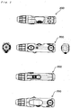
- the present invention relates to an injector used as a pricking device. More particularly, the present invention relates to an injector capable of launching "blood-sampling lancet" so as to provide a pricking.
- the pricking device In order to measure a blood sugar level of the patient with diabetes, it is required to take a sample of the blood from the patient.
- Various kinds of pricking devices have been used for sampling a small amount of the blood.
- the pricking device is generally composed of a lancet (see Patent Document listed below) and an injector.
- the lancet serves to actually prick. While on the other hand, the injector has a function of launching the lancet toward a predetermined region.
- the lancet assembly 100' is composed of a lancet 101' and a protective cover 102'.
- the lancet 101' is composed of a lancet body 104', lancet cap 106' and a pricking component 105' .
- the pricking component 105' is situated in both of the lancet body 104' and the lancet cap 106' , pricking component 105' being made of metal, the lancet body 104' and the lancet cap 106' being made of resin.
- the tip of the pricking component 105' is covered with the lancet cap 106'.
- the lancet cap 106' and the lancet body 104' are integrally connected together by a weakened part 108'.
- the protective cover 102' is provided to enclose a part of the lancet body 104'.
- Such lancet 100' is loaded into the injector 200' , and thereafter the lancet cap 106' is removed.
- the tip of the pricking component 105' is exposed, and thereby the lancet becomes ready for pricking.
- the lancet cap 106' is removed to expose the tip of the pricking component 105'. The removal of the lancet cap 106' will be described as follows:
- the inner cylinder of the lancet-attachment portion separately serves with respect to the outer cylinder of the lancet-attachment portion. More specifically, during the attaching of the lancet to the lancet-attachment portion of the plunger part, the inner cylinder of the lancet-attachment portion is displaced such that it expands outward, whereas the form of the outer cylinder of the lancet-attachment portion is maintained such that the outer cylinder is not displaced.
- a rear end side portion of the plunger part is provided with two hollow portions “A” and “B", the hollow portions “A” and “B” being adjacent in parallel to each other.
- the spring part “A” is positioned in the hollow portion "A” of the plunger part, whereas the spring part “B” is positioned in the hollow portion “B” of the plunger part.
- the spring part “B” additionally serves during an ejecting of the re-charged lancet at a point in time after the pricking.
- the axis part is flexible. It is particularly preferred that the axis part exhibits flexibility in the pricking direction and the reverse direction thereof.
- the axis part and the disk part may be provided as an integral part, the axis part and the disk part being integrated with each other. This means that the axis part and the disk part may be provided as a preliminarily integrated single part in the injector.
- the plunger part may have a hollow portion "C" at a lateral body face thereof, and the axis part may extend through such hollow portion "C". In this case, during the forward movement of the plunger part for the pricking, a part of the lateral body face of the plunger part, which defines the hollow portion "C", can hit the side face of the anisotropically-shaped portion.
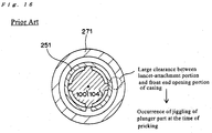
- the outer cylinder of the lancet-attachment portion which does not undergo the displacement during the insertion of the lancet, can improve the straight movement of the lancet-attachment portion of the plunger part (i.e., straight movement of the lancet) at the time of pricking since substantially no clearance is provided between the outer cylinder and the front end opening portion of the injector casing.
- the tip of the plunger part having been launched forward in no time by the force of the spring is caused to jiggle or undulate, which impairs the straight movement of the lancet.
- the plunger part 250 may be made of any suitable kinds of resin materials as long as they are used for a plunger of a pricking device in general.
- the injector casing 270 may be made of any suitable kinds of resin materials as long as they are used for a casing/housing of a pricking device in general.
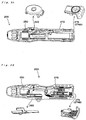
- a force necessary for the pricking is stored in the retracted plunger part 250. More specifically, a fire spring provided in the plunger part is compressed as the insertion of the lancet proceeds, and thereby the force necessary for launching the lancet is stored in the plunger part. At a point in time when the lancet can be ready for the launching after the completion of the attaching of the lancet to the plunger part, a lancet cap is removed from the lancet to expose a pricking needle.
- outer cylinder will be firstly described in more detail.
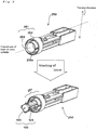
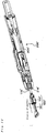
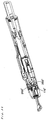
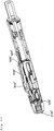
- the outer cylinder 252 of the lancet-attachment portion is provided such that substantially no clearance is provided between the outer cylinder and the front end opening portion 271 of the injector casing, as shown in Figs. 4 and 7 .
- "external body surface 252a of the outer cylinder 252 of the lancet-attachment portion” and “internal wall surface 271a of the front end opening portion 271 of the injector casing” are in close contact with or adjacent to each other, as shown in Figs. 4 and 7 .
- the phrase "close contact with or adjacent to each other" as used herein substantially means that a distance between the external body surface 252a and the internal wall surface 271a is in the approximate range of 0 to 1.4 mm, preferably in the approximate range of 0 to 1.0 mm, more preferably in the approximate range of 0 to 0.5 mm (for example, in the approximate range of 0 to 0.2 mm).
- substantially no clearance between "outer cylinder 252 of the lancet-attachment portion" and "front end opening portion 271 of the injector casing” enables the pathway of the plunger part to become more straight for the pricking.
- the tip of the plunger part having been launched forward in no time by the force of the spring is caused to jiggle or undulate, which impairs the straight movement of the lancet.
- FIG. 8 schematically shows such an embodiment that the inner cylinder 253 can be displaced to expand outward upon the loading of the lancet, and the outer cylinder cannot be displaced upon the loading of the lancet so that it keeps substantially no clearance with respect to the front end opening portion of the injector casing.
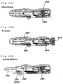
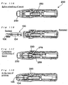
- the spring part "A" (282) provided in the plunger part is not compressed.
- an injector cap 230 is removed from the injector, and thereafter the lancet 100 is inserted into the inner cylinder 253 of the lancet-attachment portion provided at the tip of the plunger part.
- the plunger part 250 is forced to move backward. Specifically, the insertion of the lancet 100 acts to press the plunger part 250, which results in a retracting of the plunger part 250.
- the retracting of the plunger part 250 causes the spring part "A"
- the lancet cap 106 is removed from the lancet to expose the pricking needle.
- the injector cap 230 is re-attached to the injector.
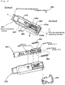
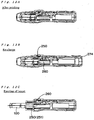
- the trigger 220 (see Fig. 11C ) is pressed toward the interior of the injector from the outside, and thereby releasing the engagement between "engaging portion of the plunger part" and “engaged portion of the trigger”. This results in an instantaneous expansion of the compressed spring "A" (282), and thereby the lancet body 104 with the pricking needle 105 exposed is launched forward in the pricking direction ( Fig. 9D ).
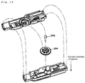
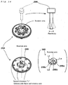
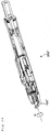
- the disk part 294 is positioned such that at least one of the side faces (295a, 295b, 295c, 295d, ⁇ ) of the anisotropically-shaped portion 295 takes a form of a perpendicular face with respect to the pricking direction, and also the axis part 296 extends along the traverse direction of the injector.
- the plunger part 250 moves forward for the pricking, a part of the plunger part hits the side face of the anisotropically-shaped portion so that a further forward movement of the plunger part is prevented.
- the scale markings on the disk part 294 has a correspondence relationship with respect to the side faces with the different spaced distances "L". According to the scale markings on the disk part 294, the user can switch the side face of the anisotropically-shaped portion 295 to the other side faces with the different spaced distances "L", the side face being hit by a part of the plunger part.
- the respective bodies of the outer cylinder 252 and the inner cylinder 253 are spaced away from each other in the lancet-attachment portion 251.
- a rib indicated by reference numeral "254" in Fig. 6 , for example) which serves to locally connect between the body of the outer cylinder and the body of the inner cylinder. The presence of the rib enables the inner cylinder located inside of the outer cylinder to be held in more stable state.
Landscapes
- Health & Medical Sciences (AREA)
- Life Sciences & Earth Sciences (AREA)
- Heart & Thoracic Surgery (AREA)
- Surgery (AREA)
- Biophysics (AREA)
- Pathology (AREA)
- Engineering & Computer Science (AREA)
- Biomedical Technology (AREA)
- Hematology (AREA)
- Medical Informatics (AREA)
- Molecular Biology (AREA)
- Physics & Mathematics (AREA)
- Animal Behavior & Ethology (AREA)
- General Health & Medical Sciences (AREA)
- Public Health (AREA)
- Veterinary Medicine (AREA)
- Dermatology (AREA)
- Pain & Pain Management (AREA)
- Measurement Of The Respiration, Hearing Ability, Form, And Blood Characteristics Of Living Organisms (AREA)
Claims (8)
- Injektor zum Starten der Lanzette, um ein Einstechen vorzusehen, wobei der Injektor umfasst:einen Kolbenteil (250), der zum Starten der Lanzette (100) in eine Einstechrichtung imstande ist; undein Injektor-Gehäuse (270), wobei sich der Kolbenteil (250) in einem Innenraum des Gehäuses (270) befindet,wobei der Kolbenteil (250) einen Lanzette-Anbringungsabschnitt (251) in seiner Spitze umfasst,dadurch gekennzeichnet, dassder Lanzette-Anbringungsabschnitt (251) eine Doppelzylinderstruktur aufweist, die aus einem Außenzylinder (252) und einem Innenzylinder gebildet ist, derart dass entsprechende Körper des Außenzylinders (252) und des Innenzylinders (253) voneinander weg beabstandet sind,wobei, wenn die Lanzette (100) an dem Lanzette-Anbringungsabschnitt (251) angebracht ist, der Innenzylinder (253) des Lanzette-Anbringungsabschnitts (251) verschoben wird, um sich nach außen auszudehnen, wohingegen der Außenzylinder (252) des Lanzette-Anbringungsabschnitts nicht verschoben wird.
- Injektor nach Anspruch 1, wobei sich der Lanzette-Anbringungsabschnitt (251) des Kolbenteils (250) im Inneren eines Vorderes-Ende-Öffnungsabschnitts des Injektorgehäuses (270) befindet, und
wobei eine Außenkörperoberfläche des Außenzylinders des Lanzette-Anbringungsabschnitts (251) und eine Innenwandoberfläche des Vorderes-Ende-Öffnungsabschnitts des Injektorgehäuses (270) in engem Kontakt miteinander oder aneinander angrenzend sind. - Injektor nach einem der Ansprüche 1 bis 2, ferner mit:einem Federteil "A" (282) zum Starten des Kolbenteils (250) in die Einstechrichtung; undeinem Federteil "B" (284) zum Zurückbringen des gestarteten Kolbenteils (250),wobei die Federteile "A" und "B" in eine Richtung senkrecht zu der Einstechrichtung parallel zueinander positioniert sind.
- Injektor nach Anspruch 3, wobei ein Hinteres-Ende-Seitenabschnitt des Kolbenteils (250) mit zwei hohlen Abschnitten "A" und "B" versehen ist, wobei die hohlen Abschnitte "A" und "B" parallel zueinander angrenzend sind,
wobei der Federteil "A" in dem hohlen Abschnitt "A" des Kolbenteils positioniert ist, wohingegen der Federteil "B" in dem hohlen Abschnitt "B" des Kolbenteils positioniert ist. - Injektor nach einem der Ansprüche 1 bis 4, ferner mit einem Einstechtiefe-Einstellmechanismus, wobei der Mechanismus umfasst:einen Scheibenteil (294), der mit einem anisotrop-geformten Abschnitt versehen ist, der Seitenflächen (295a/b/c/d) und eine Rotationsachse aufweist, wobei sich Abstandsentfernungen "L" zwischen den entsprechenden Seitenflächen und der Rotationsachse voneinander in dem anisotrop-geformten Abschnitt unterscheiden; undeinen Achsenteil (296), der sich durch die Rotationsachse des anisotrop-geformten Abschnitts erstreckt,wobei der Scheibenteil (294) derart positioniert ist, dass zumindest eine der Seitenflächen des anisotrop-geformten Abschnitts eine Form einer senkrechten Fläche in Bezug auf die Einstechrichtung annimmt,wobei sich der Achsenteil (296) in eine Querrichtung des Injektors erstreckt,wobei, wenn sich der Kolbenteil (250) für das Einstechen vorwärts bewegt, ein Teil des Kolbenteils (250) die Seitenfläche des anisotrop-geformten Abschnitts trifft, so dass eine weitere Vorwärtsbewegung des Kolbenteils (250) verhindert wird, undwobei die Seitenfläche, welche der Teil des Kolbenteils trifft, zu den anderen Seitenflächen mit den unterschiedlichen Abstandsentfernungen "L" gewechselt werden kann, durch eine derartige Drehung des Scheibenteils, dass der anisotropgeformte Abschnitt um die Rotationsachse von ihm gedreht wird, und dadurch der Abstand, über welchen sich der Kolbenteil für das Einstechen vorwärts bewegen kann, geändert wird.
- Injektor nach Anspruch 5, wobei der Achsenteil (296) flexibel ist.
- Injektor nach Anspruch 6, wobei der Achsenteil (296) Flexibilität in der Einstechrichtung und einer Rückwärtsrichtung davon aufweist.
- Injektor nach einem der Ansprüche 5 bis 7, wobei der Achsenteil und der Scheibenteil als ein integraler Teil vorgesehen sind, wobei der Achsenteil und der Scheibenteil miteinander integriert sind.
Applications Claiming Priority (2)
| Application Number | Priority Date | Filing Date | Title |
|---|---|---|---|
| JP2012114721A JP6013025B2 (ja) | 2012-05-18 | 2012-05-18 | インジェクター |
| PCT/JP2013/063181 WO2013172268A1 (ja) | 2012-05-18 | 2013-05-10 | インジェクター |
Publications (3)
| Publication Number | Publication Date |
|---|---|
| EP2851003A1 EP2851003A1 (de) | 2015-03-25 |
| EP2851003A4 EP2851003A4 (de) | 2015-10-14 |
| EP2851003B1 true EP2851003B1 (de) | 2016-10-05 |
Family
ID=49583674
Family Applications (1)
| Application Number | Title | Priority Date | Filing Date |
|---|---|---|---|
| EP13791179.8A Not-in-force EP2851003B1 (de) | 2012-05-18 | 2013-05-10 | Injektor |
Country Status (5)
| Country | Link |
|---|---|
| US (1) | US20150133818A1 (de) |
| EP (1) | EP2851003B1 (de) |
| JP (1) | JP6013025B2 (de) |
| CN (1) | CN104302230B (de) |
| WO (1) | WO2013172268A1 (de) |
Families Citing this family (1)
| Publication number | Priority date | Publication date | Assignee | Title |
|---|---|---|---|---|
| JP6549185B2 (ja) * | 2017-06-16 | 2019-07-24 | 株式会社旭ポリスライダー | インジェクター |
Family Cites Families (13)
| Publication number | Priority date | Publication date | Assignee | Title |
|---|---|---|---|---|
| JP2561697Y2 (ja) | 1992-08-28 | 1998-02-04 | アプルス株式会社 | ランセット |
| US5964718A (en) * | 1997-11-21 | 1999-10-12 | Mercury Diagnostics, Inc. | Body fluid sampling device |
| US6045567A (en) * | 1999-02-23 | 2000-04-04 | Lifescan Inc. | Lancing device causing reduced pain |
| US6283982B1 (en) * | 1999-10-19 | 2001-09-04 | Facet Technologies, Inc. | Lancing device and method of sample collection |
| DE60218170T3 (de) * | 2001-07-11 | 2011-02-24 | Arkray, Inc. | Durchstechvorrichtung |
| JP4814990B2 (ja) * | 2003-05-21 | 2011-11-16 | アークレイ株式会社 | 穿刺装置 |
| US8257380B2 (en) * | 2004-06-29 | 2012-09-04 | Stat Medical Devices, Inc. | Adjustabable disposable/single-use lancet device and method |
| DE602006015295D1 (de) * | 2005-04-04 | 2010-08-19 | Facet Technologies Llc | Lanzettenvorrichtung mit schmalem profil |
| WO2007018215A1 (ja) | 2005-08-10 | 2007-02-15 | Izumi-Cosmo Company, Limited | 穿刺デバイスならびにそれを構成するランセットアッセンブリおよびインジェクターアッセンブリ |
| EP2119396A4 (de) * | 2007-02-26 | 2010-10-13 | Nat Inst Of Advanced Ind Scien | Sensoreinrichtung |
| JP2010035687A (ja) * | 2008-08-01 | 2010-02-18 | Izumi-Cosmo Co Ltd | ランセット固定機構 |
| DE102009059035A1 (de) * | 2009-12-18 | 2011-07-28 | Lutz 73667 Scharf-Martini | Stechhilfe mit Doppelfeder |
| JP5587721B2 (ja) * | 2010-09-30 | 2014-09-10 | テルモ株式会社 | 穿刺装置 |
-
2012
- 2012-05-18 JP JP2012114721A patent/JP6013025B2/ja not_active Expired - Fee Related
-
2013
- 2013-05-10 US US14/401,662 patent/US20150133818A1/en not_active Abandoned
- 2013-05-10 EP EP13791179.8A patent/EP2851003B1/de not_active Not-in-force
- 2013-05-10 CN CN201380024893.7A patent/CN104302230B/zh not_active Expired - Fee Related
- 2013-05-10 WO PCT/JP2013/063181 patent/WO2013172268A1/ja not_active Ceased
Also Published As
| Publication number | Publication date |
|---|---|
| CN104302230A (zh) | 2015-01-21 |
| EP2851003A4 (de) | 2015-10-14 |
| CN104302230B (zh) | 2016-10-19 |
| US20150133818A1 (en) | 2015-05-14 |
| WO2013172268A1 (ja) | 2013-11-21 |
| EP2851003A1 (de) | 2015-03-25 |
| JP6013025B2 (ja) | 2016-10-25 |
| JP2013240428A (ja) | 2013-12-05 |
Similar Documents
| Publication | Publication Date | Title |
|---|---|---|
| EP2486852B1 (de) | Stechvorrichtung | |
| ES2255263T3 (es) | Jeringuilla de inyeccion con protector de la aguja tensada con un resorte. | |
| JP4847316B2 (ja) | 注射器用の針の保護装置及び注射器と針の保護装置とを備えた注射器具 | |
| US9566028B2 (en) | Lancet pricking device | |
| CN105105765B (zh) | 皮肤穿透装置 | |
| EP2653103B1 (de) | Schlagstruktur einer lanzettenvorrichtung | |
| CN101394789B (zh) | 穿刺器具 | |
| US20120095488A1 (en) | Lancet pricking device | |
| WO2011084103A1 (en) | A lancet | |
| EP2851003A1 (de) | Injektor | |
| BRPI0407945B1 (pt) | Perfurador de pele descartável | |
| JP2010035687A (ja) | ランセット固定機構 | |
| CN113144345A (zh) | 一种自动注射器用触发装置 | |
| CN109394244B (zh) | 一种偏置导正及防二次穿刺的采血笔 | |
| CN103370008B (zh) | 柳叶刀装置 | |
| EP2220999B1 (de) | Punktionsvorrichtung | |
| CN120167960A (zh) | 注射器、刺血针组件以及穿刺设备 | |
| JP5337592B2 (ja) | ランセット穿刺機構 | |
| KR20220102543A (ko) | 니들유니트 교체형 채혈기 |
Legal Events
| Date | Code | Title | Description |
|---|---|---|---|
| PUAI | Public reference made under article 153(3) epc to a published international application that has entered the european phase |
Free format text: ORIGINAL CODE: 0009012 |
|
| 17P | Request for examination filed |
Effective date: 20141114 |
|
| AK | Designated contracting states |
Kind code of ref document: A1 Designated state(s): AL AT BE BG CH CY CZ DE DK EE ES FI FR GB GR HR HU IE IS IT LI LT LU LV MC MK MT NL NO PL PT RO RS SE SI SK SM TR |
|
| AX | Request for extension of the european patent |
Extension state: BA ME |
|
| DAX | Request for extension of the european patent (deleted) | ||
| RA4 | Supplementary search report drawn up and despatched (corrected) |
Effective date: 20150911 |
|
| RIC1 | Information provided on ipc code assigned before grant |
Ipc: A61B 5/151 20060101AFI20150907BHEP |
|
| GRAP | Despatch of communication of intention to grant a patent |
Free format text: ORIGINAL CODE: EPIDOSNIGR1 |
|
| INTG | Intention to grant announced |
Effective date: 20160420 |
|
| GRAS | Grant fee paid |
Free format text: ORIGINAL CODE: EPIDOSNIGR3 |
|
| GRAA | (expected) grant |
Free format text: ORIGINAL CODE: 0009210 |
|
| AK | Designated contracting states |
Kind code of ref document: B1 Designated state(s): AL AT BE BG CH CY CZ DE DK EE ES FI FR GB GR HR HU IE IS IT LI LT LU LV MC MK MT NL NO PL PT RO RS SE SI SK SM TR |
|
| REG | Reference to a national code |
Ref country code: GB Ref legal event code: FG4D |
|
| REG | Reference to a national code |
Ref country code: CH Ref legal event code: EP |
|
| REG | Reference to a national code |
Ref country code: AT Ref legal event code: REF Ref document number: 833883 Country of ref document: AT Kind code of ref document: T Effective date: 20161015 |
|
| REG | Reference to a national code |
Ref country code: IE Ref legal event code: FG4D |
|
| REG | Reference to a national code |
Ref country code: DE Ref legal event code: R096 Ref document number: 602013012532 Country of ref document: DE |
|
| REG | Reference to a national code |
Ref country code: NL Ref legal event code: MP Effective date: 20161005 |
|
| REG | Reference to a national code |
Ref country code: LT Ref legal event code: MG4D |
|
| PG25 | Lapsed in a contracting state [announced via postgrant information from national office to epo] |
Ref country code: LV Free format text: LAPSE BECAUSE OF FAILURE TO SUBMIT A TRANSLATION OF THE DESCRIPTION OR TO PAY THE FEE WITHIN THE PRESCRIBED TIME-LIMIT Effective date: 20161005 |
|
| REG | Reference to a national code |
Ref country code: AT Ref legal event code: MK05 Ref document number: 833883 Country of ref document: AT Kind code of ref document: T Effective date: 20161005 |
|
| REG | Reference to a national code |
Ref country code: FR Ref legal event code: PLFP Year of fee payment: 5 |
|
| PG25 | Lapsed in a contracting state [announced via postgrant information from national office to epo] |
Ref country code: SE Free format text: LAPSE BECAUSE OF FAILURE TO SUBMIT A TRANSLATION OF THE DESCRIPTION OR TO PAY THE FEE WITHIN THE PRESCRIBED TIME-LIMIT Effective date: 20161005 Ref country code: LT Free format text: LAPSE BECAUSE OF FAILURE TO SUBMIT A TRANSLATION OF THE DESCRIPTION OR TO PAY THE FEE WITHIN THE PRESCRIBED TIME-LIMIT Effective date: 20161005 Ref country code: GR Free format text: LAPSE BECAUSE OF FAILURE TO SUBMIT A TRANSLATION OF THE DESCRIPTION OR TO PAY THE FEE WITHIN THE PRESCRIBED TIME-LIMIT Effective date: 20170106 Ref country code: NO Free format text: LAPSE BECAUSE OF FAILURE TO SUBMIT A TRANSLATION OF THE DESCRIPTION OR TO PAY THE FEE WITHIN THE PRESCRIBED TIME-LIMIT Effective date: 20170105 |
|
| PG25 | Lapsed in a contracting state [announced via postgrant information from national office to epo] |
Ref country code: IS Free format text: LAPSE BECAUSE OF FAILURE TO SUBMIT A TRANSLATION OF THE DESCRIPTION OR TO PAY THE FEE WITHIN THE PRESCRIBED TIME-LIMIT Effective date: 20170205 Ref country code: BE Free format text: LAPSE BECAUSE OF FAILURE TO SUBMIT A TRANSLATION OF THE DESCRIPTION OR TO PAY THE FEE WITHIN THE PRESCRIBED TIME-LIMIT Effective date: 20161005 Ref country code: HR Free format text: LAPSE BECAUSE OF FAILURE TO SUBMIT A TRANSLATION OF THE DESCRIPTION OR TO PAY THE FEE WITHIN THE PRESCRIBED TIME-LIMIT Effective date: 20161005 Ref country code: PT Free format text: LAPSE BECAUSE OF FAILURE TO SUBMIT A TRANSLATION OF THE DESCRIPTION OR TO PAY THE FEE WITHIN THE PRESCRIBED TIME-LIMIT Effective date: 20170206 Ref country code: FI Free format text: LAPSE BECAUSE OF FAILURE TO SUBMIT A TRANSLATION OF THE DESCRIPTION OR TO PAY THE FEE WITHIN THE PRESCRIBED TIME-LIMIT Effective date: 20161005 Ref country code: NL Free format text: LAPSE BECAUSE OF FAILURE TO SUBMIT A TRANSLATION OF THE DESCRIPTION OR TO PAY THE FEE WITHIN THE PRESCRIBED TIME-LIMIT Effective date: 20161005 Ref country code: RS Free format text: LAPSE BECAUSE OF FAILURE TO SUBMIT A TRANSLATION OF THE DESCRIPTION OR TO PAY THE FEE WITHIN THE PRESCRIBED TIME-LIMIT Effective date: 20161005 Ref country code: ES Free format text: LAPSE BECAUSE OF FAILURE TO SUBMIT A TRANSLATION OF THE DESCRIPTION OR TO PAY THE FEE WITHIN THE PRESCRIBED TIME-LIMIT Effective date: 20161005 Ref country code: PL Free format text: LAPSE BECAUSE OF FAILURE TO SUBMIT A TRANSLATION OF THE DESCRIPTION OR TO PAY THE FEE WITHIN THE PRESCRIBED TIME-LIMIT Effective date: 20161005 Ref country code: AT Free format text: LAPSE BECAUSE OF FAILURE TO SUBMIT A TRANSLATION OF THE DESCRIPTION OR TO PAY THE FEE WITHIN THE PRESCRIBED TIME-LIMIT Effective date: 20161005 |
|
| REG | Reference to a national code |
Ref country code: DE Ref legal event code: R097 Ref document number: 602013012532 Country of ref document: DE |
|
| PG25 | Lapsed in a contracting state [announced via postgrant information from national office to epo] |
Ref country code: EE Free format text: LAPSE BECAUSE OF FAILURE TO SUBMIT A TRANSLATION OF THE DESCRIPTION OR TO PAY THE FEE WITHIN THE PRESCRIBED TIME-LIMIT Effective date: 20161005 Ref country code: DK Free format text: LAPSE BECAUSE OF FAILURE TO SUBMIT A TRANSLATION OF THE DESCRIPTION OR TO PAY THE FEE WITHIN THE PRESCRIBED TIME-LIMIT Effective date: 20161005 Ref country code: RO Free format text: LAPSE BECAUSE OF FAILURE TO SUBMIT A TRANSLATION OF THE DESCRIPTION OR TO PAY THE FEE WITHIN THE PRESCRIBED TIME-LIMIT Effective date: 20161005 Ref country code: CZ Free format text: LAPSE BECAUSE OF FAILURE TO SUBMIT A TRANSLATION OF THE DESCRIPTION OR TO PAY THE FEE WITHIN THE PRESCRIBED TIME-LIMIT Effective date: 20161005 Ref country code: SK Free format text: LAPSE BECAUSE OF FAILURE TO SUBMIT A TRANSLATION OF THE DESCRIPTION OR TO PAY THE FEE WITHIN THE PRESCRIBED TIME-LIMIT Effective date: 20161005 |
|
| PLBE | No opposition filed within time limit |
Free format text: ORIGINAL CODE: 0009261 |
|
| STAA | Information on the status of an ep patent application or granted ep patent |
Free format text: STATUS: NO OPPOSITION FILED WITHIN TIME LIMIT |
|
| PG25 | Lapsed in a contracting state [announced via postgrant information from national office to epo] |
Ref country code: LU Free format text: LAPSE BECAUSE OF NON-PAYMENT OF DUE FEES Effective date: 20170531 Ref country code: BG Free format text: LAPSE BECAUSE OF FAILURE TO SUBMIT A TRANSLATION OF THE DESCRIPTION OR TO PAY THE FEE WITHIN THE PRESCRIBED TIME-LIMIT Effective date: 20170105 Ref country code: IT Free format text: LAPSE BECAUSE OF FAILURE TO SUBMIT A TRANSLATION OF THE DESCRIPTION OR TO PAY THE FEE WITHIN THE PRESCRIBED TIME-LIMIT Effective date: 20161005 Ref country code: SM Free format text: LAPSE BECAUSE OF FAILURE TO SUBMIT A TRANSLATION OF THE DESCRIPTION OR TO PAY THE FEE WITHIN THE PRESCRIBED TIME-LIMIT Effective date: 20161005 |
|
| 26N | No opposition filed |
Effective date: 20170706 |
|
| PG25 | Lapsed in a contracting state [announced via postgrant information from national office to epo] |
Ref country code: SI Free format text: LAPSE BECAUSE OF FAILURE TO SUBMIT A TRANSLATION OF THE DESCRIPTION OR TO PAY THE FEE WITHIN THE PRESCRIBED TIME-LIMIT Effective date: 20161005 |
|
| REG | Reference to a national code |
Ref country code: CH Ref legal event code: PL |
|
| PG25 | Lapsed in a contracting state [announced via postgrant information from national office to epo] |
Ref country code: MC Free format text: LAPSE BECAUSE OF FAILURE TO SUBMIT A TRANSLATION OF THE DESCRIPTION OR TO PAY THE FEE WITHIN THE PRESCRIBED TIME-LIMIT Effective date: 20161005 |
|
| REG | Reference to a national code |
Ref country code: IE Ref legal event code: MM4A |
|
| PG25 | Lapsed in a contracting state [announced via postgrant information from national office to epo] |
Ref country code: LI Free format text: LAPSE BECAUSE OF NON-PAYMENT OF DUE FEES Effective date: 20170531 Ref country code: CH Free format text: LAPSE BECAUSE OF NON-PAYMENT OF DUE FEES Effective date: 20170531 |
|
| PG25 | Lapsed in a contracting state [announced via postgrant information from national office to epo] |
Ref country code: LU Free format text: LAPSE BECAUSE OF NON-PAYMENT OF DUE FEES Effective date: 20170510 |
|
| REG | Reference to a national code |
Ref country code: FR Ref legal event code: PLFP Year of fee payment: 6 |
|
| PG25 | Lapsed in a contracting state [announced via postgrant information from national office to epo] |
Ref country code: IE Free format text: LAPSE BECAUSE OF NON-PAYMENT OF DUE FEES Effective date: 20170510 |
|
| PG25 | Lapsed in a contracting state [announced via postgrant information from national office to epo] |
Ref country code: MT Free format text: LAPSE BECAUSE OF NON-PAYMENT OF DUE FEES Effective date: 20170510 |
|
| PG25 | Lapsed in a contracting state [announced via postgrant information from national office to epo] |
Ref country code: HU Free format text: LAPSE BECAUSE OF FAILURE TO SUBMIT A TRANSLATION OF THE DESCRIPTION OR TO PAY THE FEE WITHIN THE PRESCRIBED TIME-LIMIT; INVALID AB INITIO Effective date: 20130510 |
|
| PGFP | Annual fee paid to national office [announced via postgrant information from national office to epo] |
Ref country code: DE Payment date: 20190523 Year of fee payment: 7 |
|
| PGFP | Annual fee paid to national office [announced via postgrant information from national office to epo] |
Ref country code: FR Payment date: 20190403 Year of fee payment: 7 |
|
| PG25 | Lapsed in a contracting state [announced via postgrant information from national office to epo] |
Ref country code: CY Free format text: LAPSE BECAUSE OF FAILURE TO SUBMIT A TRANSLATION OF THE DESCRIPTION OR TO PAY THE FEE WITHIN THE PRESCRIBED TIME-LIMIT Effective date: 20161005 |
|
| PGFP | Annual fee paid to national office [announced via postgrant information from national office to epo] |
Ref country code: GB Payment date: 20190513 Year of fee payment: 7 |
|
| PG25 | Lapsed in a contracting state [announced via postgrant information from national office to epo] |
Ref country code: MK Free format text: LAPSE BECAUSE OF FAILURE TO SUBMIT A TRANSLATION OF THE DESCRIPTION OR TO PAY THE FEE WITHIN THE PRESCRIBED TIME-LIMIT Effective date: 20161005 |
|
| PG25 | Lapsed in a contracting state [announced via postgrant information from national office to epo] |
Ref country code: TR Free format text: LAPSE BECAUSE OF FAILURE TO SUBMIT A TRANSLATION OF THE DESCRIPTION OR TO PAY THE FEE WITHIN THE PRESCRIBED TIME-LIMIT Effective date: 20161005 |
|
| PG25 | Lapsed in a contracting state [announced via postgrant information from national office to epo] |
Ref country code: AL Free format text: LAPSE BECAUSE OF FAILURE TO SUBMIT A TRANSLATION OF THE DESCRIPTION OR TO PAY THE FEE WITHIN THE PRESCRIBED TIME-LIMIT Effective date: 20161005 |
|
| REG | Reference to a national code |
Ref country code: DE Ref legal event code: R119 Ref document number: 602013012532 Country of ref document: DE |
|
| GBPC | Gb: european patent ceased through non-payment of renewal fee |
Effective date: 20200510 |
|
| PG25 | Lapsed in a contracting state [announced via postgrant information from national office to epo] |
Ref country code: GB Free format text: LAPSE BECAUSE OF NON-PAYMENT OF DUE FEES Effective date: 20200510 Ref country code: FR Free format text: LAPSE BECAUSE OF NON-PAYMENT OF DUE FEES Effective date: 20200531 |
|
| PG25 | Lapsed in a contracting state [announced via postgrant information from national office to epo] |
Ref country code: DE Free format text: LAPSE BECAUSE OF NON-PAYMENT OF DUE FEES Effective date: 20201201 |