EP2851027A1 - Ablationskathetervorrichtungen und Verfahren - Google Patents
Ablationskathetervorrichtungen und Verfahren Download PDFInfo
- Publication number
- EP2851027A1 EP2851027A1 EP20140160074 EP14160074A EP2851027A1 EP 2851027 A1 EP2851027 A1 EP 2851027A1 EP 20140160074 EP20140160074 EP 20140160074 EP 14160074 A EP14160074 A EP 14160074A EP 2851027 A1 EP2851027 A1 EP 2851027A1
- Authority
- EP
- European Patent Office
- Prior art keywords
- electrode
- tube
- ablation
- deployed
- coolant
- Prior art date
- Legal status (The legal status is an assumption and is not a legal conclusion. Google has not performed a legal analysis and makes no representation as to the accuracy of the status listed.)
- Withdrawn
Links
- 238000002679 ablation Methods 0.000 title claims abstract description 78
- 238000000034 method Methods 0.000 title claims description 58
- 210000005036 nerve Anatomy 0.000 claims abstract description 49
- 238000003825 pressing Methods 0.000 claims abstract description 49
- 230000007246 mechanism Effects 0.000 claims abstract description 17
- 230000002638 denervation Effects 0.000 claims abstract description 11
- 210000002254 renal artery Anatomy 0.000 claims description 55
- 239000002826 coolant Substances 0.000 claims description 29
- 210000000709 aorta Anatomy 0.000 claims description 28
- 230000002889 sympathetic effect Effects 0.000 claims description 10
- 206010020772 Hypertension Diseases 0.000 claims description 8
- 210000001367 artery Anatomy 0.000 claims description 8
- 210000001519 tissue Anatomy 0.000 description 65
- 230000008035 nerve activity Effects 0.000 description 15
- 230000006870 function Effects 0.000 description 14
- 238000011282 treatment Methods 0.000 description 13
- 230000000694 effects Effects 0.000 description 11
- 238000010438 heat treatment Methods 0.000 description 10
- 210000003734 kidney Anatomy 0.000 description 10
- 230000006378 damage Effects 0.000 description 7
- 229910001000 nickel titanium Inorganic materials 0.000 description 7
- 230000036772 blood pressure Effects 0.000 description 6
- 238000001816 cooling Methods 0.000 description 5
- HLXZNVUGXRDIFK-UHFFFAOYSA-N nickel titanium Chemical compound [Ti].[Ti].[Ti].[Ti].[Ti].[Ti].[Ti].[Ti].[Ti].[Ti].[Ti].[Ni].[Ni].[Ni].[Ni].[Ni].[Ni].[Ni].[Ni].[Ni].[Ni].[Ni].[Ni].[Ni].[Ni] HLXZNVUGXRDIFK-UHFFFAOYSA-N 0.000 description 5
- 230000001953 sensory effect Effects 0.000 description 5
- DGAQECJNVWCQMB-PUAWFVPOSA-M Ilexoside XXIX Chemical compound C[C@@H]1CC[C@@]2(CC[C@@]3(C(=CC[C@H]4[C@]3(CC[C@@H]5[C@@]4(CC[C@@H](C5(C)C)OS(=O)(=O)[O-])C)C)[C@@H]2[C@]1(C)O)C)C(=O)O[C@H]6[C@@H]([C@H]([C@@H]([C@H](O6)CO)O)O)O.[Na+] DGAQECJNVWCQMB-PUAWFVPOSA-M 0.000 description 4
- 210000004369 blood Anatomy 0.000 description 4
- 239000008280 blood Substances 0.000 description 4
- 230000003902 lesion Effects 0.000 description 4
- 210000000056 organ Anatomy 0.000 description 4
- 229910052708 sodium Inorganic materials 0.000 description 4
- 239000011734 sodium Substances 0.000 description 4
- 241000282414 Homo sapiens Species 0.000 description 3
- 208000027418 Wounds and injury Diseases 0.000 description 3
- 230000004913 activation Effects 0.000 description 3
- 230000002526 effect on cardiovascular system Effects 0.000 description 3
- 208000014674 injury Diseases 0.000 description 3
- 238000001356 surgical procedure Methods 0.000 description 3
- 238000012800 visualization Methods 0.000 description 3
- 208000001647 Renal Insufficiency Diseases 0.000 description 2
- 102100028255 Renin Human genes 0.000 description 2
- 108090000783 Renin Proteins 0.000 description 2
- FAPWRFPIFSIZLT-UHFFFAOYSA-M Sodium chloride Chemical compound [Na+].[Cl-] FAPWRFPIFSIZLT-UHFFFAOYSA-M 0.000 description 2
- OIRDTQYFTABQOQ-KQYNXXCUSA-N adenosine Chemical compound C1=NC=2C(N)=NC=NC=2N1[C@@H]1O[C@H](CO)[C@@H](O)[C@H]1O OIRDTQYFTABQOQ-KQYNXXCUSA-N 0.000 description 2
- 230000008901 benefit Effects 0.000 description 2
- 210000004204 blood vessel Anatomy 0.000 description 2
- 230000005779 cell damage Effects 0.000 description 2
- 208000037887 cell injury Diseases 0.000 description 2
- 230000001413 cellular effect Effects 0.000 description 2
- 210000003169 central nervous system Anatomy 0.000 description 2
- 239000002872 contrast media Substances 0.000 description 2
- 230000001276 controlling effect Effects 0.000 description 2
- 230000007423 decrease Effects 0.000 description 2
- 230000029142 excretion Effects 0.000 description 2
- 238000003780 insertion Methods 0.000 description 2
- 230000037431 insertion Effects 0.000 description 2
- 201000006370 kidney failure Diseases 0.000 description 2
- 230000004048 modification Effects 0.000 description 2
- 238000012986 modification Methods 0.000 description 2
- 230000017074 necrotic cell death Effects 0.000 description 2
- 230000001537 neural effect Effects 0.000 description 2
- 230000008816 organ damage Effects 0.000 description 2
- 230000009103 reabsorption Effects 0.000 description 2
- 230000002459 sustained effect Effects 0.000 description 2
- 230000008700 sympathetic activation Effects 0.000 description 2
- 210000002820 sympathetic nervous system Anatomy 0.000 description 2
- 230000008685 targeting Effects 0.000 description 2
- 238000002560 therapeutic procedure Methods 0.000 description 2
- 230000002792 vascular Effects 0.000 description 2
- XLYOFNOQVPJJNP-UHFFFAOYSA-N water Substances O XLYOFNOQVPJJNP-UHFFFAOYSA-N 0.000 description 2
- 241000283690 Bos taurus Species 0.000 description 1
- 239000002126 C01EB10 - Adenosine Substances 0.000 description 1
- 241000282472 Canis lupus familiaris Species 0.000 description 1
- 241000283707 Capra Species 0.000 description 1
- GJSURZIOUXUGAL-UHFFFAOYSA-N Clonidine Chemical compound ClC1=CC=CC(Cl)=C1NC1=NCCN1 GJSURZIOUXUGAL-UHFFFAOYSA-N 0.000 description 1
- 241000283086 Equidae Species 0.000 description 1
- 241000282326 Felis catus Species 0.000 description 1
- 241000282412 Homo Species 0.000 description 1
- 206010021143 Hypoxia Diseases 0.000 description 1
- 208000004404 Intractable Pain Diseases 0.000 description 1
- 241000124008 Mammalia Species 0.000 description 1
- WPNJAUFVNXKLIM-UHFFFAOYSA-N Moxonidine Chemical compound COC1=NC(C)=NC(Cl)=C1NC1=NCCN1 WPNJAUFVNXKLIM-UHFFFAOYSA-N 0.000 description 1
- 241000699670 Mus sp. Species 0.000 description 1
- 208000018737 Parkinson disease Diseases 0.000 description 1
- 241001494479 Pecora Species 0.000 description 1
- 206010037211 Psychomotor hyperactivity Diseases 0.000 description 1
- 229910001260 Pt alloy Inorganic materials 0.000 description 1
- 241000700159 Rattus Species 0.000 description 1
- 206010063897 Renal ischaemia Diseases 0.000 description 1
- 241000282887 Suidae Species 0.000 description 1
- 239000000219 Sympatholytic Substances 0.000 description 1
- 208000001871 Tachycardia Diseases 0.000 description 1
- XSQUKJJJFZCRTK-UHFFFAOYSA-N Urea Chemical compound NC(N)=O XSQUKJJJFZCRTK-UHFFFAOYSA-N 0.000 description 1
- 230000009102 absorption Effects 0.000 description 1
- 238000010521 absorption reaction Methods 0.000 description 1
- 230000036982 action potential Effects 0.000 description 1
- 229960005305 adenosine Drugs 0.000 description 1
- 230000002411 adverse Effects 0.000 description 1
- 229910045601 alloy Inorganic materials 0.000 description 1
- 239000000956 alloy Substances 0.000 description 1
- 210000003484 anatomy Anatomy 0.000 description 1
- 238000002583 angiography Methods 0.000 description 1
- 239000002333 angiotensin II receptor antagonist Substances 0.000 description 1
- 229940125364 angiotensin receptor blocker Drugs 0.000 description 1
- 210000001971 anterior hypothalamus Anatomy 0.000 description 1
- 238000003491 array Methods 0.000 description 1
- 230000004872 arterial blood pressure Effects 0.000 description 1
- 210000002565 arteriole Anatomy 0.000 description 1
- 239000002876 beta blocker Substances 0.000 description 1
- 229940097320 beta blocking agent Drugs 0.000 description 1
- 230000033228 biological regulation Effects 0.000 description 1
- 230000017531 blood circulation Effects 0.000 description 1
- 210000004556 brain Anatomy 0.000 description 1
- 239000004202 carbamide Substances 0.000 description 1
- 230000030833 cell death Effects 0.000 description 1
- 230000001684 chronic effect Effects 0.000 description 1
- 208000020832 chronic kidney disease Diseases 0.000 description 1
- 208000022831 chronic renal failure syndrome Diseases 0.000 description 1
- 229960002896 clonidine Drugs 0.000 description 1
- 230000015271 coagulation Effects 0.000 description 1
- 238000005345 coagulation Methods 0.000 description 1
- 238000004891 communication Methods 0.000 description 1
- 238000002591 computed tomography Methods 0.000 description 1
- 239000004020 conductor Substances 0.000 description 1
- 238000010276 construction Methods 0.000 description 1
- 229940039231 contrast media Drugs 0.000 description 1
- 238000013461 design Methods 0.000 description 1
- 230000001066 destructive effect Effects 0.000 description 1
- 201000010099 disease Diseases 0.000 description 1
- 208000037265 diseases, disorders, signs and symptoms Diseases 0.000 description 1
- 230000008030 elimination Effects 0.000 description 1
- 238000003379 elimination reaction Methods 0.000 description 1
- 230000003511 endothelial effect Effects 0.000 description 1
- 210000003038 endothelium Anatomy 0.000 description 1
- 238000005530 etching Methods 0.000 description 1
- 230000005284 excitation Effects 0.000 description 1
- 239000000835 fiber Substances 0.000 description 1
- 239000012530 fluid Substances 0.000 description 1
- 238000002594 fluoroscopy Methods 0.000 description 1
- 230000024924 glomerular filtration Effects 0.000 description 1
- 210000004013 groin Anatomy 0.000 description 1
- 238000001631 haemodialysis Methods 0.000 description 1
- 230000000322 hemodialysis Effects 0.000 description 1
- 230000036571 hydration Effects 0.000 description 1
- 238000006703 hydration reaction Methods 0.000 description 1
- 230000001631 hypertensive effect Effects 0.000 description 1
- 230000002267 hypothalamic effect Effects 0.000 description 1
- 230000007954 hypoxia Effects 0.000 description 1
- 238000003384 imaging method Methods 0.000 description 1
- 238000011065 in-situ storage Methods 0.000 description 1
- 238000001802 infusion Methods 0.000 description 1
- 238000002347 injection Methods 0.000 description 1
- 239000007924 injection Substances 0.000 description 1
- 230000030214 innervation Effects 0.000 description 1
- 238000009413 insulation Methods 0.000 description 1
- 230000003834 intracellular effect Effects 0.000 description 1
- 208000028867 ischemia Diseases 0.000 description 1
- 230000003907 kidney function Effects 0.000 description 1
- 239000007788 liquid Substances 0.000 description 1
- 238000002690 local anesthesia Methods 0.000 description 1
- 230000004807 localization Effects 0.000 description 1
- 238000002595 magnetic resonance imaging Methods 0.000 description 1
- 239000000463 material Substances 0.000 description 1
- 238000005259 measurement Methods 0.000 description 1
- 239000002207 metabolite Substances 0.000 description 1
- 229960003938 moxonidine Drugs 0.000 description 1
- 230000001338 necrotic effect Effects 0.000 description 1
- 230000007383 nerve stimulation Effects 0.000 description 1
- 239000012811 non-conductive material Substances 0.000 description 1
- 230000036542 oxidative stress Effects 0.000 description 1
- 210000005259 peripheral blood Anatomy 0.000 description 1
- 239000011886 peripheral blood Substances 0.000 description 1
- 210000001428 peripheral nervous system Anatomy 0.000 description 1
- 210000002970 posterior hypothalamus Anatomy 0.000 description 1
- 230000008569 process Effects 0.000 description 1
- 108090000623 proteins and genes Proteins 0.000 description 1
- 102000004169 proteins and genes Human genes 0.000 description 1
- 238000007674 radiofrequency ablation Methods 0.000 description 1
- 230000009467 reduction Effects 0.000 description 1
- 230000011514 reflex Effects 0.000 description 1
- 230000001105 regulatory effect Effects 0.000 description 1
- 230000008327 renal blood flow Effects 0.000 description 1
- 230000008660 renal denervation Effects 0.000 description 1
- 238000002271 resection Methods 0.000 description 1
- 208000015658 resistant hypertension Diseases 0.000 description 1
- 230000028327 secretion Effects 0.000 description 1
- 210000002460 smooth muscle Anatomy 0.000 description 1
- 238000005476 soldering Methods 0.000 description 1
- 210000005070 sphincter Anatomy 0.000 description 1
- 239000010935 stainless steel Substances 0.000 description 1
- 229910001256 stainless steel alloy Inorganic materials 0.000 description 1
- 230000000638 stimulation Effects 0.000 description 1
- 230000006794 tachycardia Effects 0.000 description 1
- 230000001225 therapeutic effect Effects 0.000 description 1
- 239000003053 toxin Substances 0.000 description 1
- 231100000765 toxin Toxicity 0.000 description 1
- 108700012359 toxins Proteins 0.000 description 1
- 238000012546 transfer Methods 0.000 description 1
- 230000000472 traumatic effect Effects 0.000 description 1
- 238000011269 treatment regimen Methods 0.000 description 1
- 206010044652 trigeminal neuralgia Diseases 0.000 description 1
- 238000002604 ultrasonography Methods 0.000 description 1
- 239000002441 uremic toxin Substances 0.000 description 1
- 230000002485 urinary effect Effects 0.000 description 1
- 230000006442 vascular tone Effects 0.000 description 1
- 238000003466 welding Methods 0.000 description 1
Images


Classifications
-
- A—HUMAN NECESSITIES
- A61—MEDICAL OR VETERINARY SCIENCE; HYGIENE
- A61B—DIAGNOSIS; SURGERY; IDENTIFICATION
- A61B18/00—Surgical instruments, devices or methods for transferring non-mechanical forms of energy to or from the body
- A61B18/04—Surgical instruments, devices or methods for transferring non-mechanical forms of energy to or from the body by heating
- A61B18/12—Surgical instruments, devices or methods for transferring non-mechanical forms of energy to or from the body by heating by passing a current through the tissue to be heated, e.g. high-frequency current
- A61B18/14—Probes or electrodes therefor
- A61B18/1492—Probes or electrodes therefor having a flexible, catheter-like structure, e.g. for heart ablation
-
- A—HUMAN NECESSITIES
- A61—MEDICAL OR VETERINARY SCIENCE; HYGIENE
- A61B—DIAGNOSIS; SURGERY; IDENTIFICATION
- A61B18/00—Surgical instruments, devices or methods for transferring non-mechanical forms of energy to or from the body
- A61B2018/00005—Cooling or heating of the probe or tissue immediately surrounding the probe
- A61B2018/00011—Cooling or heating of the probe or tissue immediately surrounding the probe with fluids
- A61B2018/00029—Cooling or heating of the probe or tissue immediately surrounding the probe with fluids open
-
- A—HUMAN NECESSITIES
- A61—MEDICAL OR VETERINARY SCIENCE; HYGIENE
- A61B—DIAGNOSIS; SURGERY; IDENTIFICATION
- A61B18/00—Surgical instruments, devices or methods for transferring non-mechanical forms of energy to or from the body
- A61B2018/00053—Mechanical features of the instrument of device
- A61B2018/00273—Anchoring means for temporary attachment of a device to tissue
- A61B2018/00279—Anchoring means for temporary attachment of a device to tissue deployable
-
- A—HUMAN NECESSITIES
- A61—MEDICAL OR VETERINARY SCIENCE; HYGIENE
- A61B—DIAGNOSIS; SURGERY; IDENTIFICATION
- A61B18/00—Surgical instruments, devices or methods for transferring non-mechanical forms of energy to or from the body
- A61B2018/00315—Surgical instruments, devices or methods for transferring non-mechanical forms of energy to or from the body for treatment of particular body parts
- A61B2018/00345—Vascular system
- A61B2018/00404—Blood vessels other than those in or around the heart
-
- A—HUMAN NECESSITIES
- A61—MEDICAL OR VETERINARY SCIENCE; HYGIENE
- A61B—DIAGNOSIS; SURGERY; IDENTIFICATION
- A61B18/00—Surgical instruments, devices or methods for transferring non-mechanical forms of energy to or from the body
- A61B2018/00315—Surgical instruments, devices or methods for transferring non-mechanical forms of energy to or from the body for treatment of particular body parts
- A61B2018/00434—Neural system
-
- A—HUMAN NECESSITIES
- A61—MEDICAL OR VETERINARY SCIENCE; HYGIENE
- A61B—DIAGNOSIS; SURGERY; IDENTIFICATION
- A61B18/00—Surgical instruments, devices or methods for transferring non-mechanical forms of energy to or from the body
- A61B2018/00315—Surgical instruments, devices or methods for transferring non-mechanical forms of energy to or from the body for treatment of particular body parts
- A61B2018/00505—Urinary tract
- A61B2018/00511—Kidney
-
- A—HUMAN NECESSITIES
- A61—MEDICAL OR VETERINARY SCIENCE; HYGIENE
- A61B—DIAGNOSIS; SURGERY; IDENTIFICATION
- A61B18/00—Surgical instruments, devices or methods for transferring non-mechanical forms of energy to or from the body
- A61B18/04—Surgical instruments, devices or methods for transferring non-mechanical forms of energy to or from the body by heating
- A61B18/12—Surgical instruments, devices or methods for transferring non-mechanical forms of energy to or from the body by heating by passing a current through the tissue to be heated, e.g. high-frequency current
- A61B18/14—Probes or electrodes therefor
- A61B2018/1405—Electrodes having a specific shape
- A61B2018/1407—Loop
-
- A—HUMAN NECESSITIES
- A61—MEDICAL OR VETERINARY SCIENCE; HYGIENE
- A61B—DIAGNOSIS; SURGERY; IDENTIFICATION
- A61B18/00—Surgical instruments, devices or methods for transferring non-mechanical forms of energy to or from the body
- A61B18/04—Surgical instruments, devices or methods for transferring non-mechanical forms of energy to or from the body by heating
- A61B18/12—Surgical instruments, devices or methods for transferring non-mechanical forms of energy to or from the body by heating by passing a current through the tissue to be heated, e.g. high-frequency current
- A61B18/14—Probes or electrodes therefor
- A61B2018/1465—Deformable electrodes
-
- A—HUMAN NECESSITIES
- A61—MEDICAL OR VETERINARY SCIENCE; HYGIENE
- A61B—DIAGNOSIS; SURGERY; IDENTIFICATION
- A61B18/00—Surgical instruments, devices or methods for transferring non-mechanical forms of energy to or from the body
- A61B18/04—Surgical instruments, devices or methods for transferring non-mechanical forms of energy to or from the body by heating
- A61B18/12—Surgical instruments, devices or methods for transferring non-mechanical forms of energy to or from the body by heating by passing a current through the tissue to be heated, e.g. high-frequency current
- A61B18/14—Probes or electrodes therefor
- A61B2018/1475—Electrodes retractable in or deployable from a housing
Definitions
- the present disclosure generally relates to a medical apparatus and method for treating neurovascular tissues through application of radiofrequency energy, and more particularly to an ablation apparatus for treating tissues in a patient.
- Arteries are the tube-shaped blood vessels that carry blood away from the heart to the body's tissues and organs and are each made up of outer fibrous layer, smooth muscle layer, connecting tissue and the inner lining cells (endothelium).
- Certain arteries comprise complex structures that perform multiple functions.
- the aorta is a complex structure that performs multiple functions.
- Arteries are often associated with a local network of nerves that are involved in many bodily functions including maintaining vascular tone throughout the entire body and each individual organ, sodium and water excretion or reabsorption, as in the kidney, and blood pressure control. The electrical activity to these nerves originates within the brain and the peripheral nervous system.
- the kidneys have a dense afferent sensory and efferent sympathetic innervation and are thereby strategically positioned to be the origin as well as the target of sympathetic activation. Communication with integral structures in the central nervous system occurs via afferent sensory renal nerves. Renal afferent nerves project directly to a number of areas in the central nervous system, and indirectly to the anterior and posterior hypothalamus, contributing to arterial pressure regulation. Renal sensory afferent nerve activity directly influences sympathetic outflow to the kidneys and other highly innervated organs involved in cardiovascular control, such as the heart and peripheral blood vessels, by modulating posterior hypothalamic activity. These afferent and efferent nerves traverse via the aorta to their destination end-organ site.
- renal ischemia hypoxia
- oxidative stress result in increased renal afferent activity.
- Stimulation of renal afferent nerves which may be caused by metabolites, such as adenosine, that are formed during ischemia, uremic toxins, such as urea, or electrical impulses, increases reflex in sympathetic nerve activity and blood pressure.
- An increase in renal sympathetic nerve activity increases renin secretion rate, decreases urinary sodium excretion by increasing renal tubular sodium reabsorption, and decreases renal blood flow and glomerular filtration rate.
- nervous activity to the kidney is increased, sodium and water are reabsorbed, afferent and efferent arterioles constrict, renal function is reduced, and blood pressure rises.
- Renin release may be inhibited with sympatholytic drugs, such as clonidine, moxonidine, and beta blockers.
- sympatholytic drugs such as clonidine, moxonidine, and beta blockers.
- Angiotensin receptor blockers substantially improve blood pressure control and cardiovascular effects.
- these treatments have limited efficacy and adverse effects.
- many hypertensive patients present with resistant hypertension with uncontrolled blood pressure and end organ damage due to their hypertension.
- ablative treatment applies appropriate heat (or energy) to the tissues and causes them to shrink and tighten.
- Ablative treatment devices have the advantage of using a destructive energy that is rapidly dissipated and reduced to a nondestructive level by conduction and convection forces of circulating fluids and other natural body processes.
- elevated temperature is used to ablate tissue.
- temperatures exceed 60°C cell proteins rapidly denature and coagulate, resulting in a lesion.
- the lesion can be used to resect and remove the tissue or to simply destroy the tissue, leaving the ablated tissue in place.
- Heat ablation can also be performed at multiple locations to provide a series of ablations, thereby causing the target tissue to die and necrose. Subsequent to heating, the necrotic tissue is absorbed by the body or excreted.
- Radiofrequency ablation is a high temperature, minimally invasive technique in which an active electrode is introduced in the target area, and a high frequency alternating current of up to 500 kHz, for instance, is used to heat the tissue to coagulation.
- Radiofrequency (RF) ablation devices work by sending current through the tissue, creating increased intracellular temperatures and localized interstitial heat.
- RF treatment exposes a patient to minimal side effects and risks, and is generally performed after first locating the tissue sites for treatment.
- RF energy when coupled with a temperature control mechanism, can be supplied precisely to the apparatus-to-tissues contact site to obtain the desired temperature for treating a tissue.
- RF power applied through one or more electrodes from a controlled radio-frequency (RF) instrument, the tissue is ablated.
- RF radio-frequency
- RF therapeutic protocol has been proven to be highly effective when used by electrophysiologists for the treatment of tachycardia, by neurosurgeons for the treatment of Parkinson's disease, and by neurosurgeons and anesthetists for other RF procedures such as Gasserian ganglionectomy for trigeminal neuralgia and percutaneous cervical cordotomy for intractable pains, as well as raziotomy for painful facets in the spine.
- the ablation device includes a catheter delivery mechanism including an elongated tube with a distal end and a proximal end, the distal end being placed within a body lumen at a target neurovascular region.
- a guide wire is disposed within the elongated tube.
- At least one radiofrequency electrode is initially located within the tube. The electrode being deployable from the tube at the target neurovascular region, and when deployed the electrode forms a ring-shaped structure generally centered about the tube adjacent the distal tube end.
- a plurality of positioning elements are initially located within the tube. The positioning elements are deployable from the tube at the target neurovascular region from a position of the tube further distal than the electrode.
- Pressing elements are also deployable from the tube more proximal than the electrode for use in pressing, or positioning, the deployed electrode against tissue to be ablated.
- the tissue directly in contact with the electrode is cooled, thereby enabling targeting of an ablation deeper in the tissue without ablating the tissue in direct contact with the electrode. This is a case where the nerves being targeted are actually wrapped around the outside of the aorta and the renal arteries.
- a method for performing ablation of a neurovascular structure at an artery ostium includes providing a catheter delivery mechanism including an elongated tube with a distal end and a proximal end, the distal end being emplaceable within a body lumen at a target neurovascular region, and having a guide wire within the elongated tube. Inserting the catheter delivery mechanism with its distal end at a target neurovascular region using the guide wire. At least one radiofrequency electrode initially located within the tube is provided, the electrode when deployed forming a ring-shaped structure generally centered about the tube adjacent the distal tube end.
- a plurality of positioning elements initially located within the tube are provided, the positioning elements being deployable from the tube at the target neurovascular region from a position of the tube further distal than the electrode. The positioning elements are then deployed to optimally position the electrode. The electrode is deployed at the target neurovascular region.
- a plurality of pressing elements initially located within the tube are provided, the pressing elements being deployable from the tube more proximal than the electrode for use in pressing the deployed electrode against tissue to be ablated to bring the electrode in close contact with the tissue. The electrode is pressed against the target neurovascular region, with radiofrequency energy applied through the deployed electrode from the tube at the target nerve region in an amount to ablate the targeted nerve region.
- a method for performing ablation of a renal nerve at the renal artery ostium includes providing a catheter delivery mechanism including an elongated tube with a distal end and a proximal end, the distal end being emplaceable within the body lumen at the renal artery ostium, and having a guide wire within the elongated tube for positioning the catheter delivery mechanism.
- the catheter delivery mechanism is inserted with its distal end at the renal ostium.
- At least one radiofrequency electrode initially located within the tube is provided, the electrode when deployed forms a ring-shaped structure generally centered about the tube adjacent the distal tube end.
- a plurality of positioning elements initially located within the tube are provided, the positioning elements being deployable from the tube in the renal artery at the ostium from a position of the tube further distal than the electrode.
- the positioning elements are deployed to optimally center the electrode.
- the electrode is deployed and a plurality of pressing elements initially located within the tube are provided, the pressing elements being deployable from the tube more proximal than the electrode for use in pressing the deployed electrode against ostium tissue. In one aspect, it is not the ostium but the tissue deep behind the ostium that is targeted to ablate.
- the electrode is then pressed against the ostial tissue, and radiofrequency energy is applied through the deployed electrode from the tube in a pre-specified amount to ablate the neurovascular tissue wrapped around a backside of the aorta and the renal artery.
- the device comprises a mechanism for cooling the aortic wall and the ostium in order to limit potential damage to the endothelial surface of the aorta while ablative energy is effectively transmitted to the adventitial layer.
- This cooling mechanism is by means of coolant or chilled material circulated through a hollow tube of the electrode, thus providing protection to the aortic wall at the level of the energy delivery.
- the present disclosure is also directed to a method for radio-frequency (RF) heat ablation of tissue through the use of one or more RF electrodes, which are deployed from the distal end of a catheter.
- the catheter may be inserted into the body via a natural orifice, a stoma or a surgically created opening that is made for the purpose of inserting the catheter, and insertion of the catheter may be facilitated with the use of a guide wire or a generic support structure or visualization apparatus.
- the catheter is advanced through the body to the relevant location, such as in the aorta at the location of the ostium of the renal artery.
- RF energy is applied to the RF electrodes in order to effect changes in the target tissue.
- Heat is generated by supplying a suitable energy source to the apparatus, which is comprised of at least one electrode that is in contact with the body tissues.
- coolant - either stagnant or circulating - may be employed to cool the inner surface of the vessel wall. This coolant function may provide a form of protection or insulation to the inner vessel wall surface during RF energy activation and heat transfer.
- the ablation is performed for the ablation of aortic nerve activity that leads specifically to the kidney.
- proximal refers to a portion of an instrument closer to an operator, while “distal” refers to a portion of the instrument farther away from the operator.
- subject refers in an embodiment to a mammal including a human in need of therapy for, or susceptible to, a condition or its sequelae.
- the subject or patient may include dogs, cats, pigs, cows, sheep, goats, horses, rats, and mice and humans.
- FIG. 1 illustrates an embodiment of an ablation device 10 for delivering radiofrequency energy to the walls of a body lumen.
- the device is used for interaortic renal artery ablation for renal artery sympathetic neural ablation.
- Radiofrequency energy is delivered to the walls of the renal artery or aorta.
- radiofrequency energy is delivered using a nonconductive catheter.
- the device 10 includes a substantially tubular catheter 12, called a delivery catheter, namely an elongated, thin, tube-like device, having proximal and distal ends, preferably constructed from a nonconductive material.
- the delivery catheter 12 can be any type of catheter, as are well known to those in the art, having a proximal end for manipulation by an operator and a distal end for operation within a patient. The distal end and proximal end preferably form one continuous piece, but need not be in a single piece.
- the delivery catheter 12 is used as a delivery system for delivering one or more radiofrequency electrodes to the desired site for nerve ablation.
- the delivery catheter 12 has about a 2.55 mm outer diameter and about a 0.09 mm or less inner diameter.
- the device 10 includes a guide wire 14 that may be advanced into the patient, e.g., through the delivery catheter 12.
- the guide wire 14 extends, through (within) the delivery catheter 12.
- the guide wire 14 here has a 0.035" thickness (or could employ other thicknesses as known in the art).
- the guide wire 14 is inserted into the patient's vascular system, e.g. through the groin, and advanced to the desired location.
- the delivery catheter 12 is inserted into the patient and threaded over the guide wire 14 to the desired location.
- the device 10 may be advanced to the desired location within the patient's vascular system with, e.g., a rapid exchange (RX) or over-the-wire wire (OTW) delivery system, with the 0.035" or smaller guide wire 14 employed for the device 10.
- Radiographic control may be employed and contrast media may also be injected at the beginning of the procedure to assist in manipulation and positioning of the instruments.
- the device 10 includes one or more electrodes 16 deployable from the delivery catheter 12 adjacent the distal end of the delivery catheter 12.
- the one or more electrodes 16 are capable of conducting radiofrequency (RF) energy. Initially, or when the one or more electrodes 16 are in a non-deployed position, the one or more electrodes 16 are located within the delivery catheter 12.
- the electrode 16 is here in the form of a hollow tube, for example, a nitinol or other nickel-titanium alloy hypotube.
- the hollow tube 16 may be connected to a coolant source (e.g., coolant source 102 illustrated in FIG. 7 ), for example, a cold saline solution, and other coolants.
- the coolant may be circulated through the hollow tube, when performing the ablative function.
- the coolant may also be discharged into the patient through an end of the hypotube, and the coolant may be carried out of the patient through the patient's blood stream.
- the use of the coolant may assist in controlling the ablative temperature of or applied to the tissue to be ablated, and reduce thermal injury to the aorta and renal artery, in particular the intima of the vessels.
- a target region deeper in the tissue for example, tissue deep behind the ostium
- the target nerve region a region wrapped around the outside of the aorta and the renal arteries, to be ablated when the device is deployed within the aorta and renal arteries.
- the device can be used for interaortic renal artery ablation for renal artery sympathetic neural ablation.
- the nickel-titanium alloy or nitinol hypotube of the electrode 16 is an alloy that has both super-elasticity and shape memory, i.e., remembers its original cold-forged shape, and returns to a pre-deformed shape when heated. This allows the electrode 16 to be deformed during the retracting and deploying of the electrode 16 into and from the delivery catheter 12, and when heated, for example, by application of radiofrequency (RF) energy, form the ring-shape structure described herein.
- RF radiofrequency
- the electrode 16 includes a stem portion extending from an aperture (for example, an electrode aperture 22 described below), and a curved portion extending from the stem portion, forming ring-shape structure or arc around the delivery catheter 12.
- the electrodes 16 may be positioned such that, when the device 10 is in a deployed position, the electrodes 16 together form the ring-shape structure or are oriented concentrically, such that they together provide essentially 360° coverage around a target area.
- the more than one electrodes 16 may be nested or placed in parallel so as to form the ring-shape structure.
- Each of the nested electrodes 16 may include a stem portion, and a first portion curving or extending from the stem portion. The plural electrodes are spaced around the axis of the catheter so that the curved portions form a rough circular shape when deployed.
- the one or more electrodes 16 may include a braid, coil, or laser cut tubular covering over the one or more electrodes 16. This tubular covering may be used in the deployment and retraction of the one or more electrodes 16 from the delivery catheter 12. The tubular covering may also function to adjust a diameter of the ring-shape structure to deploy the one or more electrodes 16 such that the ring-shape structure provides essentially 360° coverage around a target area.
- the device 10 in this embodiment includes one or more positioning elements 18 deployable from the delivery catheter 12 adjacent the distal end of the delivery catheter 12. Initially, or when the one or more positioning elements 18 are in a non-deployed position, the one or more positioning elements 18 are located within the delivery catheter 12. The one or more positioning elements 18 are deployable from the delivery catheter 12 at a target region from a position of the delivery catheter 12 further distal than the one or more electrodes 16. In use, this allows the positioning elements 18 to position and secure device 10 at the desired location within a vessel, e.g., the aorta in the area of the renal artery ostium. The one or more positioning elements 18 are used so that the one or more electrodes 16 can operate at the precise location, namely around the renal artery ostium.
- the electrode(s) 16 could ablate tissue that is not intended to be affected, causing undesired damage.
- the positioning elements 18 should properly center the electrode 16 circumferentially around the renal artery ostium, namely the opening to the renal artery.
- the one or more positioning elements 18 in this embodiment are wire loops and are located symmetrically around the delivery catheter 12.
- the positioning elements 18 may be deployed approximately to the diameter of the renal artery, so as to locate the electrode 16 from being moved distally or proximally relative to the renal artery, so as to allow the device 10 to hold its position within the renal artery relative to the aorta.
- the electrode 16 may then be positioned against the renal artery ostium to perform the ablative function, as will be shortly described.
- the device 10 includes one or more pressing elements 20 deployable from the delivery catheter 12 proximal to the electrode 16. Initially, or when the one or more pressing elements 20 are in a non-deployed position, the one or more pressing elements 20 are located within the delivery catheter 12. The one or more pressing elements 20 are deployable from the delivery catheter 12 once the device is at a target nerve region, and from a position of the delivery catheter 12 more proximal than the one or more electrodes 16. When deployed, the pressing elements 20 may be used to press the deployed one or more electrodes 16 against the tissue to be ablated.
- the pressing elements 20 are wire loops and are located symmetrically around the delivery catheter 12.
- the pressing elements 20 may advance the delivery catheter 12 distally such that the delivery catheter 12 presses against a proximally-facing surface of the one or more electrodes 16 to then be manipulated to push the one or more electrodes 16 distally against the renal artery ostium.
- the one or more electrodes 16 When the one or more electrodes 16 are pressed up against the renal artery ostium of the aorta, the one or more electrodes 16, which are positioned in a circular configuration, contact the renal artery ostium of the aorta. Heat may then be generated to the one or more electrodes 16 by supplying a suitable RF energy source, and the ablation is performed for the elimination (or interruption) of nerve activity, such as nerve activity that leads specifically to the kidney.
- Each of the one or more electrodes 16, the one or more positioning elements 18 and the one or more pressing elements 20 may be selectively and independently movable between a non-deployed position (or retracted) and a deployed position, and back to the non-deployed position. Alternatively, they could be joined in a manner such that they are deployed together as a group
- the electrode 16, the positioning elements 18 and the pressing elements 20 of device 10 are retracted within the delivery catheter 12.
- the delivery catheter 12 includes an electrode aperture 22, positioning element apertures 24 and pressing element apertures 26.
- the electrode aperture 22, the positioning element apertures 24 and the pressing element apertures 26 allow the electrode 16, the positioning elements 18 and the pressing elements 20 to be extended out of the delivery catheter 12, to their respective deployed positions.
- a distance between the distal end of the delivery catheter 12 and the electrode aperture 22 and/or the electrode 16 is about 10 mm to about 20 mm in length.
- a distance between the positioning element apertures 24 and the electrode aperture 22 and/or the electrode 16 is about 5 mm to about 7 mm in length.
- the delivery catheter 12 is advanced longitudinally through the blood vessel, e.g., over guide wire 14, to the relevant location within the body lumen, such as within the aorta, and into the desired position within the inner circumference of the vessel, such as at the renal artery ostium of the aorta.
- the electrode 16, the positioning elements 18 and the pressing elements 20 are deployed.
- the positioning elements 18 are deployed first, then the electrode 16 followed by the pressing elements 20. This order need not be the only order, however.
- the electrode 16 is in the deployed position for operation within the patient.
- the electrode 16 extends out of the delivery catheter 12 through the electrode aperture 22, forming the ring-shape structure generally positioned in a circular configuration centered around the delivery catheter 12, such that the electrode 16 provides essentially 360° coverage at the target nerve region.
- the electrode 16 can be pressed up against and put into contact with the renal artery ostium of the aorta, for instance, to ablate the nerve activity circumferentially around the ostium.
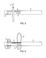
- the positioning elements 18 and the pressing elements 20 are in the deployed position, for operation within the patient.
- the positioning elements 18 and the pressing elements 20 extend out of the delivery catheter 12 through the positioning element apertures 24 and the pressing element apertures 26, respectively.
- the electrode 16, the positioning elements 18 and the pressing elements 20 are all in the deployed position for operation within the patient.
- the electrode 16 To return to the non-deployed position, as for withdrawal, the electrode 16, the positioning elements 18 and the pressing elements 20 are retracted into the inner diameter of delivery catheter 12.
- the device includes more than one electrodes 16' deployable from a delivery catheter 12' adjacent the distal end of the delivery catheter 12'.
- the electrodes 16' are similarly capable of conducting RF energy. Initially, or when the electrodes 16' are in a non-deployed position, the electrodes 16' are located within the delivery catheter 12'.
- the electrodes 16' when deployed, are positioned such that, when the device is in a deployed position, the electrodes 16' together form a ring-shape structure, or are oriented concentrically, such that they together provide (perhaps roughly) essentially 360° coverage around a target area. As illustrated in FIG.
- Electrodes 16' there are four electrodes 16', but there can be fewer electrodes or more electrodes, each of which include a stem portion extending radially from the respective aperture 26' in the delivery catheter 12', and a curved portion extending from the stem portion. The curved portions align to form a ring-shape structure or arc around the delivery catheter 12'.
- the electrodes 16' may also include the braid, coil, or laser cut tubular covering over the electrodes 16', as described above with reference to electrode 16.
- the delivery catheter 12' also includes electrode apertures 26' to allow the electrodes 16' to be extended out of the delivery catheter 12' to their respective deployed positions.
- the device may also include the one or more positioning elements, the one or more pressing elements, and the delivery catheter 12' may include their respective apertures, such that the device functions is essentially the same manner as described above with respect to FIGS. 1-5 .
- the positioning elements 18 operate to position, center, and secure the device at the desired location. This is accomplished by insertion of the unexpanded distal end of the delivery catheter 12/12' at least partially into the entrance of the renal artery so as to serve, by deployment of the positioning elements 18, as an anchor for the device within the aorta so that the electrodes 16/16' can perform their ablative function.
- the one or more pressing elements 20 operate to engage the one or more electrodes 16/16' at the desired location. This is accomplished by using the pressing elements 20 so as to push the one or more electrodes 16/16' against the tissue to be ablated so that the one or more electrodes 16/16' can perform their ablative function.
- the proximal end of the device includes at least one port for connection to a source of radiofrequency (RF) power (e.g., RF power source 104 illustrated in FIG. 7 ).
- RF radiofrequency
- the device can be coupled to a source of RF energy, such as RF in about the 300 kilohertz to 500 kilohertz range.
- the electrodes 16/16' may be electrically coupled to the RF energy source through this port.
- the device may also be connected to coolant source, and a control unit for sensing and measurement of other factors, such as temperature, conductivity, pressure, impedance and other variables, such as nerve energy.
- the one or more electrodes 16/16' are electrically connected to the radiofrequency (RF) energy source.
- the RF energy source may be an external RF control unit that provides RF energy to the one or more electrodes 16/16'.
- all the electrodes 16/16' are attached to the same wire such that they are made to operate together.
- the electrodes 16/16' may also have wires that loosely connect them, in order for them to be connected electrically.
- the one or more electrodes 16/16' operate to provide radiofrequency energy for heating of the desired location during the nerve ablation procedure.
- the one or more electrodes 16/16' may be constructed of any suitable conductive material, as is known in the art. Examples include stainless steel and platinum alloys.
- the one or more electrodes 16/16' are in a preferred form, hollow tubes, for example, nitinol hypotubes.
- the nitinol hypotubes may be a 4 x 0.018 mm nitinol hypotube.
- the hollow tube may be connected to a coolant source (e.g., coolant source 102 illustrated in FIG. 7 ), for example, a cold saline solution, and other coolants both gas and liquid.
- the coolant is circulated through the hollow tube, when performing the ablative function. This may assist in controlling the ablative temperature applied to the tissue to be ablated, and reduce thermal injury to the aorta and renal artery. For example, this may limit the thermal effect to about a 3 mm to about a 6 mm depth, for example, from the level of the renal artery ostium.
- the cooling allows a target region deeper in the tissue (for example, tissue deep behind the ostium) to be ablated without ablating the tissue in close proximity to the electrode. This allows the target nerve region, a region wrapped around the outside of the aorta and the renal arteries, to be ablated.
- the one or more electrodes 16/16' may operate in either bipolar or monopolar mode, with a ground pad electrode.
- a monopolar mode of delivering RF energy a single electrode is used in combination with an electrode patch that is applied to the body to form the other electrical contact and complete an electrical circuit.
- a bipolar operation is possible when two or more electrodes are used, such as two concentric electrodes.
- the one or more electrodes 16/16' can be attached to an electrode delivery member, such as the wire frame, by the use of soldering or welding methods which are well known to those skilled in the art.
- the one or more electrodes 16/16' are oriented in a generally circular configuration.
- the diameter of the circular or ring-shape of the electrodes 16/16' is determined by the width of the aortic artery branch for which denervation is desired. If the diameter of the circular or ring-shape of the electrodes 16/16' is smaller than the diameter of the aortic artery branch for which denervation is desired, the one or more electrodes 16/16' would not actually be in contact with tissue, and no ablation would occur.
- the diameter of the circular or ring-shape of the electrodes 16/16' should be at least that distance, i.e., 7 mm, in order to properly provide ablation surrounding the renal artery ostium.
- the diameter of the circular or ring-shape of the electrodes 16/16' may be calculated with reference to the renal artery ostium.
- the diameter of the circular or ring-shape of the electrodes 16/16' that surround the imaging catheter may have a 10 mm to about a 15 mm diameter.
- the one or more electrodes 16/16' can be disposed to treat tissue by delivering radiofrequency (RF) energy.
- the radiofrequency energy delivered to the electrode may have a frequency of about 5 kilohertz (kHz) to about 1 GHz.
- the RF energy may have a frequency of about 10 kHz to about 1000 MHz; specifically about 10 kHz to about 10 MHz; more specifically about 50 kHz to about 1 MHz; even more specifically about 300 kHz to about 500 kHz.
- each electrode can be operated separately or in combination with another as sequences of electrodes disposed in arrays. Treatment can be directed at a single area or several different areas of a vessel by operation of selective electrodes.
- An electrode selection and control switch may include an element that is disposed to select and activate individual electrodes.
- the RF power source may have multiple channels, delivering separately modulated power to each electrode. This reduces preferential heating that occurs when more energy is delivered to a zone of greater conductivity and less heating occurs around electrodes that are placed into less conductive tissue. If the level of tissue hydration or the blood infusion rate in the tissue is uniform, a single channel RF power source may be used to provide power for generation of lesions relatively uniform in size.
- cell injury includes all cellular effects resulting from the delivery of energy from the electrodes up to, and including, cell necrosis.
- Use of the catheter device can be accomplished as a relatively simple medical procedure with local anesthesia.
- cell injury proceeds to a depth of approximately 1-5 mm from the surface of the mucosal layer of sphincter or that of an adjoining anatomical structure.
- Renal nerve activity may be measured through the same mechanism as that required for energy delivery and the electrodes.
- Nerve activity may be typically measured by one of two means.
- Proximal nerve stimulation can occur by means of transmitting an electrical impulse to the catheter.
- Action potentials can be measured from the segment of the catheter situated within a more distal portion of the nerve.
- the quantity of downstream electrical activity as well as the time delay of electrical activity from the proximal to distal electrodes will be provide a measure of residual nerve activity post nerve ablation.
- the second means of measuring nerve activity is to measure ambient electrical impulses prior to and post nerve ablation within a site more distal than the ablation site.
- the one or more electrodes 16/16' operate to provide radiofrequency energy for both heating and temperature sensing.
- the one or more electrodes 16/16' can be used for heating during the ablation procedure and can also be used for sensing of nerve activity prior to ablation as well as after ablation has been done.
- the one or more electrodes 16/16' may also be coupled to a sensor or a control unit (e.g., control unit 106 illustrated in FIG. 7 ) capable of measuring such factors as temperature, conductivity, pressure, impedance and other variables.
- the device may have a thermistor that measures temperature in the lumen, and a thermistor may be a component of a microprocessor-controlled system that receives temperature information from the thermistor and adjusts wattage, frequency, duration of energy delivery, or total energy delivered to the one or more electrodes 16/16'.
- a closed loop, feedback control system may be incorporated to optimize the delivery of ablative energy to the tissue.
- the device may also be coupled to a visualization apparatus, such as a fiber optic device, a fluoroscopic device, an anoscope, a laparoscope, an endoscope or the like.
- a visualization apparatus such as a fiber optic device, a fluoroscopic device, an anoscope, a laparoscope, an endoscope or the like.
- devices coupled to the visualization apparatus are controlled from a location outside the body, such as by an instrument in an operating room or an external device for manipulating the inserted catheter.
- the device may be constructed with markers that assist the operator in obtaining a desired placement, such as radio-opaque markers, etchings or microgrooves.
- markers that assist the operator in obtaining a desired placement
- device may be constructed to enhance its imageability by techniques such as ultrasounds, CAT scan or MRI.
- radiographic contrast material may be injected through a hollow interior of the catheter through an injection port, thereby enabling localization by fluoroscopy or angiography.
- a method for performing ablation of a nerve at an artery ostium includes inserting a distal end of a device, for example, device 10 including the delivery catheter 12/12', at a target nerve region using a guide wire.
- the targeted neurovascular region may be the renal artery ostium.
- This method includes deploying one or more positioning elements, for example, positioning elements 18, from the delivery catheter 12/12' to position the device and an electrode, for example, electrodes 16/16', for deployment within the target nerve region.
- the positioning elements may center and secure the device, for example, the delivery catheter 12/12', in the target nerve region.
- the method includes deploying the electrode, for example, electrodes 16/16', from the delivery catheter 12/12' at the target nerve region.
- the electrode When deployed, the electrode may form a ring-shaped structure generally centered around the delivery catheter 12/12' adjacent the distal end.
- the ring-shaped structure may also extend substantially circumferentially around the target nerve region.
- the method of this embodiment includes deploying one or more pressing elements, for example, pressing elements 20, from the delivery catheter 12/12' (either before or after electrode deployment) at a position more proximal than the electrode, for example, electrodes 16/16'.
- the pressing elements may be used for pressing the deployed electrode, for example, electrodes 16/16', against tissue to be ablated at the target nerve region.
- the method may also include pressing the deployed electrode, for example, electrodes 16/16', against tissue at the target nerve region.
- Radiofrequency (RF) energy is applied through the deployed electrode, for example, electrodes 16/16', in an amount to ablate tissue at the target nerve region.
- the radiofrequency energy may be applied at a single energy level for a defined and regulated period of time or at a first energy level and at least a second energy level which is different from the first energy level.
- the first and second energy levels may be alternated and pulsed. Further, there may be a defined pause between the delivery of each energy level to allow the tissue temperature to normalize.
- the method may include circulating a coolant through the hollow tube electrodes during the ablation procedure.
- the method includes the step of precooling the target nerve area, for example by circulating the coolant through the hollow tube electrodes.
- the precooling may be performed for any period of time, particularly about 10 seconds to about 20 seconds, and more particularly for about 15 seconds.
- the radiofrequency energy may be applied at the first energy level.
- the first energy level is about 1.4 amps, and is applied for about 60 seconds to about 90 seconds.
- the radiofrequency energy may be applied at the second energy level.
- the second energy level is about 1.2 amps, and is applied for about 90 seconds.
- a pause may also be incorporated between the delivery of the first and second energy level.
- the ablation procedure incudes applying the radiofrequency energy at a first energy level for a first period of time, followed by a rest and then applying the radiofrequency energy at a second energy level for a second period of time.
- the first energy level and the second energy level may be equal.
- the first period of time and the second period of time may be equal.
Landscapes
- Health & Medical Sciences (AREA)
- Life Sciences & Earth Sciences (AREA)
- Surgery (AREA)
- Engineering & Computer Science (AREA)
- Plasma & Fusion (AREA)
- Medical Informatics (AREA)
- Otolaryngology (AREA)
- Physics & Mathematics (AREA)
- Cardiology (AREA)
- Biomedical Technology (AREA)
- Heart & Thoracic Surgery (AREA)
- Nuclear Medicine, Radiotherapy & Molecular Imaging (AREA)
- Molecular Biology (AREA)
- Animal Behavior & Ethology (AREA)
- General Health & Medical Sciences (AREA)
- Public Health (AREA)
- Veterinary Medicine (AREA)
- Surgical Instruments (AREA)
Applications Claiming Priority (1)
| Application Number | Priority Date | Filing Date | Title |
|---|---|---|---|
| US201361793024P | 2013-03-15 | 2013-03-15 |
Publications (1)
| Publication Number | Publication Date |
|---|---|
| EP2851027A1 true EP2851027A1 (de) | 2015-03-25 |
Family
ID=50343617
Family Applications (1)
| Application Number | Title | Priority Date | Filing Date |
|---|---|---|---|
| EP20140160074 Withdrawn EP2851027A1 (de) | 2013-03-15 | 2014-03-14 | Ablationskathetervorrichtungen und Verfahren |
Country Status (3)
| Country | Link |
|---|---|
| EP (1) | EP2851027A1 (de) |
| JP (1) | JP2014180574A (de) |
| KR (1) | KR20140113506A (de) |
Cited By (9)
| Publication number | Priority date | Publication date | Assignee | Title |
|---|---|---|---|---|
| US9827041B2 (en) | 2002-04-08 | 2017-11-28 | Medtronic Ardian Luxembourg S.A.R.L. | Balloon catheter apparatuses for renal denervation |
| US9827040B2 (en) | 2002-04-08 | 2017-11-28 | Medtronic Adrian Luxembourg S.a.r.l. | Methods and apparatus for intravascularly-induced neuromodulation |
| US9848947B2 (en) * | 2013-12-11 | 2017-12-26 | Boston Scientific Scimed, Inc. | Devices and methods for prostate tissue ablation and/or resection |
| US9919144B2 (en) | 2011-04-08 | 2018-03-20 | Medtronic Adrian Luxembourg S.a.r.l. | Iontophoresis drug delivery system and method for denervation of the renal sympathetic nerve and iontophoretic drug delivery |
| US10588682B2 (en) | 2011-04-25 | 2020-03-17 | Medtronic Ardian Luxembourg S.A.R.L. | Apparatus and methods related to constrained deployment of cryogenic balloons for limited cryogenic ablation of vessel walls |
| US10709490B2 (en) | 2014-05-07 | 2020-07-14 | Medtronic Ardian Luxembourg S.A.R.L. | Catheter assemblies comprising a direct heating element for renal neuromodulation and associated systems and methods |
| CN112807077A (zh) * | 2021-02-24 | 2021-05-18 | 成都安捷畅医疗科技有限公司 | 收缩式消融电极 |
| US11135004B2 (en) | 2018-12-24 | 2021-10-05 | Industrial Technology Research Institute | Ablation device |
| WO2024109562A1 (zh) * | 2022-11-23 | 2024-05-30 | 昆山雷盛医疗科技有限公司 | 射频热消融系统及其分段功率控制方法 |
Families Citing this family (1)
| Publication number | Priority date | Publication date | Assignee | Title |
|---|---|---|---|---|
| KR102332559B1 (ko) * | 2019-12-11 | 2021-11-26 | 건양대학교 산학협력단 | 스텐트 삽입장치 |
Citations (5)
| Publication number | Priority date | Publication date | Assignee | Title |
|---|---|---|---|---|
| WO2001037925A2 (en) * | 1999-11-22 | 2001-05-31 | Boston Scientific Limited | Atrial annulus ablation loop with expandable pusher |
| WO2001072373A2 (en) * | 2000-03-24 | 2001-10-04 | Transurgical, Inc. | Apparatus and method for intrabody thermal treatment |
| WO2002045608A2 (en) * | 2000-12-08 | 2002-06-13 | Medtronic, Inc. | Ablation catheter assembly and method for isolating a pulmonary vein |
| US20020111618A1 (en) * | 1999-04-05 | 2002-08-15 | Stewart Mark T. | Ablation catheter assembly with radially decreasing helix and method of use |
| US20120116382A1 (en) * | 2010-10-25 | 2012-05-10 | Medtronic Ardian Luxembourg S.A.R.L. | Catheter apparatuses having multi-electrode arrays for renal neuromodulation and associated systems and methods |
-
2014
- 2014-03-14 EP EP20140160074 patent/EP2851027A1/de not_active Withdrawn
- 2014-03-14 JP JP2014051755A patent/JP2014180574A/ja active Pending
- 2014-03-14 KR KR1020140030150A patent/KR20140113506A/ko not_active Withdrawn
Patent Citations (5)
| Publication number | Priority date | Publication date | Assignee | Title |
|---|---|---|---|---|
| US20020111618A1 (en) * | 1999-04-05 | 2002-08-15 | Stewart Mark T. | Ablation catheter assembly with radially decreasing helix and method of use |
| WO2001037925A2 (en) * | 1999-11-22 | 2001-05-31 | Boston Scientific Limited | Atrial annulus ablation loop with expandable pusher |
| WO2001072373A2 (en) * | 2000-03-24 | 2001-10-04 | Transurgical, Inc. | Apparatus and method for intrabody thermal treatment |
| WO2002045608A2 (en) * | 2000-12-08 | 2002-06-13 | Medtronic, Inc. | Ablation catheter assembly and method for isolating a pulmonary vein |
| US20120116382A1 (en) * | 2010-10-25 | 2012-05-10 | Medtronic Ardian Luxembourg S.A.R.L. | Catheter apparatuses having multi-electrode arrays for renal neuromodulation and associated systems and methods |
Cited By (12)
| Publication number | Priority date | Publication date | Assignee | Title |
|---|---|---|---|---|
| US9827041B2 (en) | 2002-04-08 | 2017-11-28 | Medtronic Ardian Luxembourg S.A.R.L. | Balloon catheter apparatuses for renal denervation |
| US9827040B2 (en) | 2002-04-08 | 2017-11-28 | Medtronic Adrian Luxembourg S.a.r.l. | Methods and apparatus for intravascularly-induced neuromodulation |
| US10105180B2 (en) | 2002-04-08 | 2018-10-23 | Medtronic Ardian Luxembourg S.A.R.L. | Methods and apparatus for intravascularly-induced neuromodulation |
| US10376311B2 (en) | 2002-04-08 | 2019-08-13 | Medtronic Ardian Luxembourg S.A.R.L. | Methods and apparatus for intravascularly-induced neuromodulation |
| US10420606B2 (en) | 2002-04-08 | 2019-09-24 | Medtronic Ardian Luxembourg S.A.R.L. | Methods and apparatus for performing a non-continuous circumferential treatment of a body lumen |
| US9919144B2 (en) | 2011-04-08 | 2018-03-20 | Medtronic Adrian Luxembourg S.a.r.l. | Iontophoresis drug delivery system and method for denervation of the renal sympathetic nerve and iontophoretic drug delivery |
| US10588682B2 (en) | 2011-04-25 | 2020-03-17 | Medtronic Ardian Luxembourg S.A.R.L. | Apparatus and methods related to constrained deployment of cryogenic balloons for limited cryogenic ablation of vessel walls |
| US9848947B2 (en) * | 2013-12-11 | 2017-12-26 | Boston Scientific Scimed, Inc. | Devices and methods for prostate tissue ablation and/or resection |
| US10709490B2 (en) | 2014-05-07 | 2020-07-14 | Medtronic Ardian Luxembourg S.A.R.L. | Catheter assemblies comprising a direct heating element for renal neuromodulation and associated systems and methods |
| US11135004B2 (en) | 2018-12-24 | 2021-10-05 | Industrial Technology Research Institute | Ablation device |
| CN112807077A (zh) * | 2021-02-24 | 2021-05-18 | 成都安捷畅医疗科技有限公司 | 收缩式消融电极 |
| WO2024109562A1 (zh) * | 2022-11-23 | 2024-05-30 | 昆山雷盛医疗科技有限公司 | 射频热消融系统及其分段功率控制方法 |
Also Published As
| Publication number | Publication date |
|---|---|
| JP2014180574A (ja) | 2014-09-29 |
| KR20140113506A (ko) | 2014-09-24 |
Similar Documents
| Publication | Publication Date | Title |
|---|---|---|
| US20160074112A1 (en) | Ablation catheters and methods of use thereof | |
| EP2851027A1 (de) | Ablationskathetervorrichtungen und Verfahren | |
| US12114915B2 (en) | Methods and systems for the treatment of polycystic ovary syndrome | |
| US12048467B2 (en) | Methods and systems for the manipulation of ovarian tissues | |
| WO2012174375A1 (en) | Radiofrequency ablation catheter device | |
| WO2012122157A1 (en) | Radiofrequency ablation catheter device | |
| EP3052038B1 (de) | Elektrochirurgisches myomablationssystem | |
| EP2677953A2 (de) | Funkfrequenzablations-kathetervorrichtung | |
| US20080097139A1 (en) | Systems and methods for treating lung tissue | |
| US20190298442A1 (en) | Bi-polar tissue ablation device and methods of use thereof | |
| KR101415900B1 (ko) | 고주파 열치료용 중첩형 바이폴라 전극 | |
| WO2017147253A1 (en) | Methods for selective treatment of renal sympathetic nerves | |
| CN105792765A (zh) | 用于在身体器官内的身体组织中产生线性损伤的装置 | |
| US20160331447A1 (en) | Method and apparatus for selective treatment inside a body lumen |
Legal Events
| Date | Code | Title | Description |
|---|---|---|---|
| PUAI | Public reference made under article 153(3) epc to a published international application that has entered the european phase |
Free format text: ORIGINAL CODE: 0009012 |
|
| 17P | Request for examination filed |
Effective date: 20140314 |
|
| AK | Designated contracting states |
Kind code of ref document: A1 Designated state(s): AL AT BE BG CH CY CZ DE DK EE ES FI FR GB GR HR HU IE IS IT LI LT LU LV MC MK MT NL NO PL PT RO RS SE SI SK SM TR |
|
| R17P | Request for examination filed (corrected) |
Effective date: 20150925 |
|
| RBV | Designated contracting states (corrected) |
Designated state(s): AL AT BE BG CH CY CZ DE DK EE ES FI FR GB GR HR HU IE IS IT LI LT LU LV MC MK MT NL NO PL PT RO RS SE SI SK SM TR |
|
| 17Q | First examination report despatched |
Effective date: 20151221 |
|
| STAA | Information on the status of an ep patent application or granted ep patent |
Free format text: STATUS: THE APPLICATION IS DEEMED TO BE WITHDRAWN |
|
| 18D | Application deemed to be withdrawn |
Effective date: 20160701 |