EP2851108A1 - Vorderbacken für eine Skibindung - Google Patents
Vorderbacken für eine Skibindung Download PDFInfo
- Publication number
- EP2851108A1 EP2851108A1 EP20140405068 EP14405068A EP2851108A1 EP 2851108 A1 EP2851108 A1 EP 2851108A1 EP 20140405068 EP20140405068 EP 20140405068 EP 14405068 A EP14405068 A EP 14405068A EP 2851108 A1 EP2851108 A1 EP 2851108A1
- Authority
- EP
- European Patent Office
- Prior art keywords
- radial bearing
- holding
- coupling element
- elements
- ski
- Prior art date
- Legal status (The legal status is an assumption and is not a legal conclusion. Google has not performed a legal analysis and makes no representation as to the accuracy of the status listed.)
- Granted
Links
Images


Classifications
-
- A—HUMAN NECESSITIES
- A63—SPORTS; GAMES; AMUSEMENTS
- A63C—SKATES; SKIS; ROLLER SKATES; DESIGN OR LAYOUT OF COURTS, RINKS OR THE LIKE
- A63C9/00—Ski bindings
- A63C9/08—Ski bindings yieldable or self-releasing in the event of an accident, i.e. safety bindings
- A63C9/085—Ski bindings yieldable or self-releasing in the event of an accident, i.e. safety bindings with sole hold-downs, e.g. swingable
- A63C9/08535—Ski bindings yieldable or self-releasing in the event of an accident, i.e. safety bindings with sole hold-downs, e.g. swingable with a mobile body or base or single jaw
- A63C9/0855—Ski bindings yieldable or self-releasing in the event of an accident, i.e. safety bindings with sole hold-downs, e.g. swingable with a mobile body or base or single jaw pivoting about a vertical axis
-
- A—HUMAN NECESSITIES
- A63—SPORTS; GAMES; AMUSEMENTS
- A63C—SKATES; SKIS; ROLLER SKATES; DESIGN OR LAYOUT OF COURTS, RINKS OR THE LIKE
- A63C9/00—Ski bindings
- A63C9/005—Ski bindings with means for adjusting the position of a shoe holder or of the complete binding relative to the ski
-
- A—HUMAN NECESSITIES
- A63—SPORTS; GAMES; AMUSEMENTS
- A63C—SKATES; SKIS; ROLLER SKATES; DESIGN OR LAYOUT OF COURTS, RINKS OR THE LIKE
- A63C9/00—Ski bindings
- A63C9/08—Ski bindings yieldable or self-releasing in the event of an accident, i.e. safety bindings
- A63C9/0807—Ski bindings yieldable or self-releasing in the event of an accident, i.e. safety bindings for both towing and downhill skiing
-
- A—HUMAN NECESSITIES
- A63—SPORTS; GAMES; AMUSEMENTS
- A63C—SKATES; SKIS; ROLLER SKATES; DESIGN OR LAYOUT OF COURTS, RINKS OR THE LIKE
- A63C9/00—Ski bindings
- A63C9/08—Ski bindings yieldable or self-releasing in the event of an accident, i.e. safety bindings
- A63C9/085—Ski bindings yieldable or self-releasing in the event of an accident, i.e. safety bindings with sole hold-downs, e.g. swingable
- A63C9/08557—Details of the release mechanism
- A63C9/08564—Details of the release mechanism using cam or slide surface
-
- A—HUMAN NECESSITIES
- A63—SPORTS; GAMES; AMUSEMENTS
- A63C—SKATES; SKIS; ROLLER SKATES; DESIGN OR LAYOUT OF COURTS, RINKS OR THE LIKE
- A63C9/00—Ski bindings
- A63C9/08—Ski bindings yieldable or self-releasing in the event of an accident, i.e. safety bindings
- A63C9/085—Ski bindings yieldable or self-releasing in the event of an accident, i.e. safety bindings with sole hold-downs, e.g. swingable
- A63C9/08557—Details of the release mechanism
- A63C9/08578—Details of the release mechanism using a plurality of biasing elements
-
- A—HUMAN NECESSITIES
- A63—SPORTS; GAMES; AMUSEMENTS
- A63C—SKATES; SKIS; ROLLER SKATES; DESIGN OR LAYOUT OF COURTS, RINKS OR THE LIKE
- A63C9/00—Ski bindings
- A63C9/08—Ski bindings yieldable or self-releasing in the event of an accident, i.e. safety bindings
- A63C9/085—Ski bindings yieldable or self-releasing in the event of an accident, i.e. safety bindings with sole hold-downs, e.g. swingable
- A63C9/08557—Details of the release mechanism
- A63C9/08585—Details of the release mechanism using transverse biasing element
Definitions
- the invention relates to a toe for a ski binding.
- This front jaw comprises a base element, a radial bearing with a pivot axis, which is arranged in a substantially vertically oriented, extending in the longitudinal direction of the plane, an elastic element, at least two shock elements, which are arranged around the radial bearing, and a holding element for holding a ski boot in Area of a ski boot top.
- the holding element is mounted by the radial bearing about the pivot axis pivotally mounted on the base element and has a holding position for holding the ski boot.
- the holding element starting from the holding position in Skiquerides on both sides is pivotable, whereby a lateral safety release is made possible.
- This front jaw comprises a housing, in the rear region of an intermediate piece is arranged. At this intermediate piece, a holding part for holding the front end of a ski boot sole is attached.
- the housing has in its front region a bore in which a piston is displaceably guided in the longitudinal direction of the housing and acted upon by a spring with a rearwardly directed force.
- the housing in a central region on a downwardly open recess. In this recess engages a part of the system, which points upwards from a mountable to a ski base plate.
- the piston presses against a front surface of the plant part with an area from front to back, so that the plant part is pressed against the intermediate piece. Therefore, the intermediate piece rests on the wide rear side of the abutment part when the toe piece is in a hold position for holding a ski boot.
- the housing can be pivoted together with the holding part to the system part with a lateral safety release. In such a pivoting movement and the intermediate piece is pivoted relative to the rear side of the system part, so that it is supported at the lateral edge of the wide rear side of the plant part is moved slightly backwards. As a result, the housing and the holding part are also moved backwards somewhat seen in the longitudinal direction of the ski.
- the piston arranged in the housing is pivoted relative to the contact part with the pivoting movement.
- the surface of the piston is tilted with respect to the forward-facing front surface of the abutment.
- the piston in the housing is moved forward against the force of the spring. Accordingly, the front jaw can absorb energy in a shock on a ski shoe held in the toe until it comes to a lateral safety release.
- the disadvantage of this front jaw is that the energy absorbed by the toe piece depends not only on the distance traveled by the piston and the force of the spring, but also on external forces acting on the holder and the housing. This is because the contact part is clamped between the intermediate piece and the piston and that the holding part, the intermediate piece and the housing relative to the contact part in the ski longitudinal direction are movable. As a result, a forward or backward force on the holding member or housing changes the energy consumable by the toe box.
- the holding part, the intermediate piece and the housing during a rotational movement about the contact part are moved slightly backwards, whereby the holding part pushes backwards against the ski boot held in the ski binding and the ski boot accordingly causes a forwardly directed force on the holding part ,
- the ski boot held in the ski binding also influences the energy that can be absorbed by the toe piece without any additional force.
- This front jaw comprises a holding part for holding the front end of a ski boot sole, which is mounted pivotably about a vertical axis on a base part. In a front region in front of the vertical axis, this holding part has a flat surface.
- the holding part is held in a holding position, in which the flat surface is aligned in the front region of the holding part parallel to the abutting surface of the piston.
- ski longitudinal direction means along the orientation of the longitudinal axis of the ski.
- skiparallel means aligned for an elongate object along the longitudinal axis of the ski.
- ski-parallel means aligned parallel to the sliding surface of the ski.
- ski direction means a direction transverse to the ski longitudinal direction, which, however, need not be oriented exactly at right angles to the longitudinal axis of the ski.
- ski center means a center of the ski as viewed in the ski direction, while the term “ski manifest” does not mean that it can move in relation to the ski.
- ski manifest does not mean that it can move in relation to the ski.
- front, rear, top, “bottom” and “side” refer to “front”, “rear”, “top”, “bottom” and “side” of the ski.
- horizontal and vertical refer to the ski, with “horizontal” lying in a ski-parallel plane and “vertical” oriented perpendicular to this plane.
- the object of the invention is to provide a front jaw belonging to the technical field mentioned above, which allows both an optimally controlled lateral safety release as well as a compact design permits.
- the toe piece comprises a coupling element, which is aligned essentially perpendicular to the pivot axis and is movable substantially radially relative to the radial bearing and thus relative to the base element and relative to the retaining element.
- the at least two joint elements are coupled to one another via the coupling element.
- a first of the at least two mating elements along the coupling element relative to the coupling element and radially to the radial bearing movably mounted and pressed by the first elastic member in the direction of the radial bearing, whereby the coupled via the coupling element at least two Stossetti with a substantially equal force against the Radial bearings are pressed.
- the radial bearing and at least one of the at least two joint elements are shaped and cooperate in such a way that the retaining element can be pressed to the holding position by a force generated by the first elastic element and acting against the radial bearing by the stub elements.
- the radial bearing can be a pin mounted in a journal bearing. But it may also be, for example, a ball or roller bearings or a differently designed radial bearing. It is only important that the radial bearing allows a pivoting movement of the holding element relative to the base element about the pivot axis and prevents a translational movement of the holding element relative to the base element perpendicular to the pivot axis.
- the at least two joint elements can be arranged in different ways around the radial bearing.
- the at least two joint elements can be pressed directly or indirectly via one or more other element against the radial bearing.
- the first of the at least two joint elements which is mounted so as to be movable along the coupling element relative to the coupling element and radially to the radial bearing, may for example be movably mounted on the coupling element.
- this first of the at least two joint elements can also not be movably mounted on the coupling element but on one or more other elements of the front jaw so that it can be moved radially along the coupling element to the radial bearing.
- the holding element may be movably mounted on the holding element, so that it can be moved radially along the coupling element to the radial bearing.
- the first of the at least two joint elements but also be movably mounted on the base element, so that it is movable along the coupling element radially to the radial bearing.
- the first of the at least two die elements can be movably mounted on the coupling element, on the holding element or on the base element and also on one or more further elements of the front jaw, so that it is radially movable along the coupling element to the radial bearing.
- the first of the at least two mating elements can be movably mounted along a linear path on the coupling element or on one or more other elements of the front jaw.
- This linear path can be both straight and curved. However, it is at least partially aligned along the coupling element radially to the radial bearing and thus to the pivot axis.
- the first of the at least two joint elements can also be mounted pivotably about a physical or a geometrical axis on the coupling element or on one or more other elements of the front jaw.
- the physical or geometric axis is arranged such that pivotal movement of the first of the at least two mating elements results in a region of the first of the at least two mating elements remote from the physical or geometric axis being radially movable toward the radial bearing along the coupling element.
- the first of the at least two joint elements is pivotally mounted both along a linear path and about a physical or geometric axis pivotally mounted on the coupling element or on another element of the front jaw.
- the first of the at least two mating elements which is mounted so as to be movable along the coupling element radially to the radial bearing, may be one of the at least one of the at least two mating elements, which is shaped such that it interacts with the radial bearing in such a way that the holding element is moved by one of the generated first elastic element and acting through the stub elements against the radial bearing force can be pressed to the holding position.
- the first of the at least two joint elements can also not be shaped such that it cooperates with the radial bearing in such a way that the retaining element can be pressed to the holding position by a force generated by the first elastic element and acting against the radial bearing by the stub elements.
- the first of the at least two bluff elements differs from the at least one of the at least two bluff elements, which is shaped to be so with the radial bearing cooperates, that the holding element can be pressed by a force generated by the first elastic element and acting through the stub elements against the radial bearing force to the holding position.
- the coupling element may be formed, for example, elongated or flat. In both cases, the coupling element is aligned substantially perpendicular to the pivot axis. If the coupling element is elongate, this means that a longitudinal axis of the coupling element is aligned substantially perpendicular to the pivot axis.
- the first of the at least two joint elements which is mounted so as to be movable along the coupling element so as to be movable radially with respect to the pivot axis, is movable along the longitudinal axis of the coupling element.
- the coupling element is designed to be flat, this means that a plane which is defined by the planar coupling element is aligned essentially perpendicular to the pivot axis.
- the first of the at least two joint elements, which is mounted so as to be movable along the coupling element radially to the pivot axis is movable along the plane which is defined by the planar coupling element.
- the first elastic element can be produced in one piece or in several pieces. If the first elastic element is made in several pieces, for example, there is the possibility that it comprises only one elastic part for generating the force by means of which the first of the at least two joint elements can be pressed in the direction of the radial bearing.
- a multi-piece finished first elastic element may also comprise a plurality of elastic parts which may be arranged in parallel or in series to generate the force by which the first of the at least two joint elements can be pressed in the direction of the radial bearing.
- the elastic element may be in each of the elastic parts, for example a spring, a steel spring, or even act of a made of an elastic material such as rubber element.
- the first elastic element for example, be biased in the toe, that it draws two of its ends to each other by a tensile force.
- the elastic element may, for example, also be prestressed in such a way that it presses two of its ends away from one another by a pushing force.
- a first advantage of the solution according to the invention is that an optimally controlled lateral safety release is made possible. This is achieved, on the one hand, in that the retaining element is mounted on the base element so as to be pivotable about the pivot axis by the radial bearing and thus can not be moved radially relative to the pivot axis.
- the optimally controlled safety release is achieved in that the coupling element is substantially radially movable to the radial bearing and that the at least two bluff elements are coupled together via the coupling element, wherein a first of the at least two bluff elements along the coupling element relative to the coupling element and radially movable to the radial bearing is mounted and can be pressed by the first elastic element in the direction of the radial bearing, whereby the coupled via the coupling element at least two mating elements with a substantially equal force against the radial bearing press.
- the retaining element when an external force acts on the retaining element, the retaining element is securely supported by the radial bearing on the base element, while the coupling element and the at least two joint elements are not affected by this force, since they are movable relative to the radial bearing. Accordingly, the energy that can be absorbed by the toe until it comes to a lateral safety release, largely independent of external forces.
- the inventive front jaw allows an optimally controllable safety release. This advantage is achieved regardless of whether the toe is used in an alpine ski binding or touring ski binding.
- a second advantage of the inventive solution is that a compact construction of the front jaw is made possible because the at least two joint elements are arranged around the radial bearing and thus the mechanism, which allows a lateral safety release to the radial bearing can be arranged in a compact manner around the radial bearing ,
- the at least two mating elements are pivotable about the pivot axis together with the holding element relative to the base element, when the holding element is pivoted about the pivot axis, or if the at least two mating elements at an equal angle to Swivel axis as the base element remain when the support member is pivoted about the pivot axis.
- the front jaw for a ski binding comprises a base element, a radial bearing with a pivot axis which is arranged in a substantially vertically oriented, extending in the longitudinal direction of the plane, an elastic element, at least two joint elements, which are arranged around the radial bearing, and a holding element for holding a ski boot in the area of a ski boot tip.
- the holding element is mounted by the radial bearing about the pivot axis pivotally mounted on the base element and has a holding position for holding the ski boot.
- the holding element starting from the holding position in Skiquerides on both sides is pivotable, whereby a lateral safety release is made possible.
- the front jaw comprises a coupling element, which is aligned substantially perpendicular to the pivot axis and substantially radially to the radial bearing and thus relative to the base element and relative to the holding element is movable.
- the at least two joint elements are coupled to one another via the coupling element, wherein a first of the at least two joint elements is movably mounted along the coupling element relative to the coupling element and radially to the pivot axis and is pressed by the first elastic element in the direction of the radial bearing.
- the coupled via the coupling element at least two joint elements are pressed with a substantially equal force against the radial bearing.
- the radial bearing at least a positioning structure and at least one of the mating elements has a counter-structure to the at least one positioning structure.
- the at least one stub element with its counter-structure is located on the corresponding at least one positioning structure, as a result of which the at least two stub elements are at a first distance from one another.
- the at least one stub element is moved away with its counter-structure of the corresponding at least one positioning structure, whereby the at least two Stossetti are at a distance from each other, which is greater than the first distance, so that the holding element by a The force caused by the first elastic element is pressed to the holding position.
- This has the advantage that the force caused by the first elastic element is optimally deflected into a restoring force, which biases the holding element towards the holding position.
- This advantage is achieved independently of whether only one of the at least two joint elements has a counter-structure or whether more than one of the at least two joint elements has a counter-structure. If only one of the at least two mating elements has a counter-structure, the advantage is achieved independently of which of the at least two mating elements has this counter-structure.
- the front jaw comprises more than one of the at least one positioning structure
- these positioning structures are spatially delimited from one another by the fact that a respective stub element with its counterstructure can be located on each of the positioning structures.
- a transition from a positioning structure to an adjacent positioning structure can be formed continuously, ie without structural separation.
- a transition from a positioning structure to an adjacent positioning structure can also be formed by a structural separation. Accordingly, it is also irrelevant whether the positioning structures are made together from a single piece, or whether each of the positioning structures is made as a separate piece.
- the at least one positioning structure may be formed, for example, as a recess or as a bulge. If more than one positioning structure is present, for example, each of the positioning structures can be formed as a recess or as a bulge. If it is a recess in a positioning structure, the counter-structure may be formed, for example, as a bulge. On the other hand, if a positioning structure is designed as a bulge, the counterstructure can be designed, for example, as an indentation.
- a guide can be formed by the shape of the at least one positioning structure and the counter-structure which, depending on the rotational position of the holding element about the pivot axis allows a certain minimum distance between the at least one Stosselement with the counter-structure and the pivot axis. This minimum distance can be smallest, when the holding element is in the holding position and become larger, the farther the holding element is moved away from the holding position.
- the at least two joint elements are coupled to one another via the coupling element and pressed against the radial bearing, it can be achieved with such a guide that the at least two joint elements are at a first distance from each other when the retaining element is in the holding position, and that the at least two mating elements are at a distance from one another which is greater than the first distance when the holding element is moved away from the holding position.
- the at least one positioning structure can also be embodied differently than indentation or as a bulge.
- the counter-structure may also be designed differently than a bulge or as an indentation.
- the at least one positioning structure and the counter-structure may be formed as a flat surface.
- the at least one positioning structure and the or the Stossieri may be arranged with a counter-structure such that rests in the holding position of the holding element, the at least one positioning with its planar surface area on the flat surface of the counter-structure of the corresponding Stosselements.
- the holding element is pivoted away from the holding position about the pivot axis, then the flat surface of the counter-structure is tilted relative to the respective flat surface of the positioning structure.
- This form the at least one positioning structure and the counter-structure a guide which, depending on the rotational position of the holding element about the pivot axis allows a certain minimum distance between the at least one Stosselement with the counter-structure and the pivot axis. This minimum distance is smallest when the holding element is in the holding position and becomes larger the farther the holding element is moved away from the holding position.
- the at least two joint elements are coupled to one another via the coupling element and pressed against the radial bearing, it is achieved with such a guide that the at least two joint elements are at a first distance from each other when the retaining element is in the holding position, and that the at least two mating elements are at a distance from one another which is greater than the first distance when the holding element is moved away from the holding position.
- the number of the at least one positioning structure is preferably equal to or greater than the number of die elements with a counter-structure. This makes it possible that each mating element can be positioned with its counter-structure on a positioning structure. This has the advantage that the force generated by the first elastic element is optimally used to push the holding element in the holding position. Alternatively, there is also the possibility that the number of at least one positioning structure is smaller than the number of die elements with a counter-structure. Such an alternative may have the advantage that the manufacture of the toe piece is easier because fewer positioning structures are needed.
- preferred embodiments of the front jaw can also be designed differently. In the following it will be shown on the basis of advantageous features how such other preferred embodiments can be formed. Of course, however, the abovementioned, preferred embodiment with the at least one positioning structure and the counter-structure may also comprise one or more of these advantageous features.
- the holding element comprises a rigidly formed region, which has on both sides to the rear reaching ends which are shaped so that they in the
- Holding position of the holding element laterally grip around a ski boot held in the toe piece.
- This has the advantage that the holding element in the holding position laterally supports the ski boot held in the front jaw with the rigidly formed area on both sides. This allows the ski boot to be held optimally in the toe.
- the rigidly formed area is formed from a single piece or from a plurality of rigidly connected individual pieces. Regardless, there is the possibility that further movable elements are arranged on the rigidly formed area.
- rollers may be mounted on the rigidly formed area, which facilitate movement of the ski boot held in the toe piece away from the toe piece in the event of a lateral safety release by reducing a possible frictional resistance between the holding element and the ski boot.
- the holding element does not comprise such a rigidly formed area.
- the holding element comprises an upper portion, which extends slightly rearwardly to at least partially surround the sole of a ski boot held in the toe piece.
- another element of the front jaw comprises, as the retaining element, a region which extends somewhat rearward in order to at least partially surround the sole of a ski boot held in the front jaw.
- the holding element and one or more further elements of the front jaw each comprise an area which extends somewhat rearward to at least partially surround the sole of a ski boot held in the toe piece.
- no element of the front jaw comprises an area which extends somewhat backwards in order to at least partially surround the sole of a ski boot held in the front jaw.
- an element of the front jaw can have a region reaching backwards, which engage in a recess in the ski boot and thus follow the ski boot can support up.
- the coupling element is movable in a plane perpendicular to the pivot axis relative to the radial bearing.
- This has the advantage that the coupling element is movable not only radially to the radial bearing, but in all directions in the plane perpendicular to the pivot axis. Accordingly, the coupling element can act compensating when an external force acts on the retaining element. This makes it possible for the at least two impact element to press against the radial bearing substantially unaffected by the external force. Accordingly, this allows a reliable controllable lateral safety release of the toe piece.
- the coupling element is movable only substantially radially to the radial bearing.
- the first elastic member has first and second ends, wherein the first end of the first elastic member is located farther from the radial bearing than the second end of the first elastic member, and wherein the first end of the first elastic member is supported against the coupling member while the second end of the first elastic member is supported against the first of the at least two thrusting members, which is movably supported along the coupling member relative to the coupling member and radially to the radial bearing.
- This has the advantage that the force produced by the first elastic element can be optimally transmitted to the first of the at least two joint elements and to the coupling element. This allows optimal control of a lateral safety release.
- the first elastic element is supported directly on the first of the at least two joint elements or directly on the coupling element, or if an interposed support element is arranged on the first of the at least two joint elements or on the coupling element the first elastic element is supported.
- the first elastic element exerts a tensile force and pulls the two locations where it is supported against the coupling element or against the Stosselement towards each other, or whether the first elastic element exerts a shock force and the two points where it is supported against the coupling element or against the Stosselement, push away from each other.
- the first end of the first elastic element is supported relative to a first end of the coupling element.
- the first end of the coupling element is a longitudinal end of the coupling element, if the coupling element is elongated. If, however, the coupling element has a substantially triangular, quadrangular or pentagonal shape, then the first end of the coupling element is located at a corner of the coupling element. If, however, the coupling element is of star-shaped design, the first end of the coupling element is located at a tip of a star-shaped serrated point.
- the coupling element has a disk-like shape with a rounded edge
- the first end of the coupling element is located at a location on the edge of the coupling element.
- this has the advantage that the space around the radial bearing can be optimally utilized, since the elastic element can extend from the first of the at least two joint elements to the first end of the coupling element. Accordingly, a larger and thus stronger elastic element can be used per unit volume of the toe. This allows a compact construction of the front jaw, wherein the front jaw for its size can absorb a relatively large amount of energy until it comes to a safety release.
- the first end of the first elastic element is supported relative to a region of the coupling element, which is offset from the first end of the coupling element inwardly toward the radial bearing.
- the first elastic element not with respect to the coupling element, but with respect to another element of the Front jaw such as the support member or the base member is supported.
- a second mating element of the at least two mating elements is movably mounted along the coupling element relative to the coupling element and radially to the radial bearing, wherein the front jaw comprises a second elastic element, by means of which this second mating element can be pressed against the radial bearing.
- the second stub element can for example be movably mounted on the coupling element.
- it can not be movably mounted on the coupling element, but on one or more other elements of the front jaw, so that it can be moved along the coupling element radially to the radial bearing.
- the toe piece has two elastic elements, which both contribute to the at least two mating elements coupled to one another via the coupling element being pressed against the radial bearing with a substantially equal force. Accordingly, the force with which the at least two joint elements are pressed against the radial bearing can be increased by the second elastic element. As a result, the size of the toe piece can absorb more energy until a lateral safety release occurs.
- a second mating element of the at least two mating elements is movably mounted along the coupling element relative to the coupling element and radially to the radial bearing and the toe piece comprises a second elastic element
- the second elastic element advantageously has a first and a second end, wherein the first end of the second elastic member disposed farther from the radial bearing than the second end of the second elastic member, and wherein the first end of the second elastic member is supported against the coupling member while the second end of the second elastic member is supported against the second pushing member.
- the second elastic element is supported directly on the second of the at least two joint elements or directly on the coupling element, or if an interposed support element is arranged on the second of the at least two joint elements or on the coupling element the second elastic element is supported.
- the second elastic element exerts a tensile force and the two points at which it is supported relative to the coupling element or against the Stosselement, draws toward each other, or whether the second elastic element exerts a shock force and the both locations where it is supported against the coupling element and against the stub element, push away from each other.
- the first end of the second elastic element is supported relative to a second end of the coupling element.
- the second end of the coupling element is a longitudinal end of the coupling element, if that Coupling element is elongated. If, however, the coupling element has a substantially triangular, quadrangular or pentagonal shape, then the second end of the coupling element is located at a corner of the coupling element. However, if the coupling element is formed in a star shape, then the second end of the coupling element is located at a tip of a serrated star.
- the coupling element has a disk-like shape with a rounded edge
- the second end of the coupling element is located at a location on the edge of the coupling element.
- this has the advantage that the space around the radial bearing can be optimally utilized since the second elastic element can extend from the second of the at least two joint elements to the second end of the coupling element. Accordingly, a larger and thus stronger elastic element can be used per unit volume of the toe. Accordingly, a compact construction of the front jaw is made possible, wherein the front jaw for its size can absorb a relatively large amount of energy until it comes to a safety release.
- the first end of the second elastic element is supported relative to a region of the coupling element, which is offset from the second end of the coupling element inwardly toward the radial bearing.
- the second elastic element is not supported relative to the coupling element, but relative to another element of the front jaw, such as the holding element or the base element.
- the radial bearing comprises two positioning structures.
- the first stamping element and a further stamping element of the at least two stamping elements each have a counter-structure to one of these two positioning structures.
- the two positioning structures and the counter-structures of the two die elements are preferably shaped such that the first die element and the further Stosselement with the respective counter-structure on the corresponding positioning structure, when the holding element is in the holding position, whereby the at least two Stossetti are at a first distance from each other.
- the two positioning structures and the counter-structures of the two die elements are preferably shaped such that the first die element and the further die element with the respective counter-structure is moved away from the corresponding positioning structure, when the retaining element is moved away from the holding position, whereby the at least two die elements in are at a distance from each other, which is greater than the first distance, so that the holding element can be pressed by a force caused by the first elastic element to the holding position.
- the farther the holding element is moved away from the holding position the greater is preferably the distance between the at least two injection elements.
- the retaining element can preferably be pressed to the holding position by a force exerted by the first elastic element and by the second elastic element.
- the two positioning structures can be designed, for example, as indentations or as bulges. If it is indentations, the counter-structures may be formed, for example, as bulges. On the other hand, if the two positioning structures are formed as bulges, the counter-structures can be formed, for example, as indentations.
- a guide can be formed by the shape of the two positioning structures and the counter-structures which, depending on the rotational position of the holding element about the pivot axis allows a certain minimum distance between the two Stoss instituten with the counter-structures and the pivot axis. This minimum distance can be the smallest, when the holding element in the holding position are and grow larger, the farther the retaining element is moved away from the holding position.
- the at least two joint elements are coupled to one another via the coupling element and pressed against the radial bearing, it can be achieved with such a guide that the at least two joint elements are at a first distance from each other when the retaining element is in the holding position, and that the at least two mating elements are at a distance from one another which is greater than the first distance when the holding element is moved away from the holding position.
- both the two positioning structures and the two counter-structures may be formed as a flat surface.
- the two positioning structure and the or the two Stoss may be arranged with their counter-structures such that in the holding position of the holding element, the two positioning structures lie flat with their flat surfaces on the flat surface of the counter-structure of the corresponding Stosselements. If the holding element is pivoted away from the holding position about the pivot axis from this starting position, the flat surfaces of the two counter-structures are tilted relative to the respective flat surface of the corresponding positioning structure.
- the two positioning structures and the two counter-structures form guides which, depending on the rotational position of the retaining element about the pivot axis, allow a certain minimum distance between the interference elements with counter-structure and the pivot axis. This minimum distance is smallest, when the holding element is in the holding position and becomes larger, the farther the holding element is pivoted away from the holding position.
- the at least two mating elements are coupled to one another via the coupling element and pressed against the radial bearing, it is achieved with these guides that the at least two mating elements are at a first distance from each other when the holding element is in the holding position, and that the at least two Stossieri are at a distance from each other, which is greater than the first distance, when the holding member is moved away from the holding position.
- this has the advantage that the force generated by the first elastic element and possibly the second elastic element can be optimally used to to press the holding element in the holding position.
- this is at least one of the at least two joint elements, which is shaped and cooperates with the radial bearing, that the holding element is pressed by a force generated by the first elastic element and acting through the mating elements against the radial bearing force to the holding position together with the holding element relative to the base element pivotable about the pivot axis.
- the at least one of the at least two bluff elements and the radial bearing are preferably arranged such that the at least one of the at least two bluff elements cooperates with a region of the radial bearing which remains at the same angle to the pivot axis as the base element, when the retaining element around the Swivel axis is pivoted.
- the at least one of the at least two push elements is moved relative to this region of the radial bearing when the holding element is moved away from the holding position.
- At least one positioning structure is arranged on the radial bearing in this first preferred variant, one of these at least one positioning structure is preferably arranged in the region of the radial bearing, which remains at the same angle to the pivot axis as the base element, when the retaining element is pivoted about the pivot axis.
- the radial bearing is a journal mounted in a counterpart and if the journal is arranged on the retaining element while the counterpart is arranged on the base element, then this positioning structure is preferably arranged on the counterpart.
- the pin is arranged on the base element, while the counterpart is arranged on the holding element, then this positioning structure is preferably arranged on the pin.
- the at least one of the at least two mating elements which is shaped in such a way and cooperates with the radial bearing, that the holding element can be pressed by a force generated by the first elastic element and acting through the mating elements against the radial bearing force to the holding position, so arranged on the front jaw that it remains at an equal angle to the pivot axis as the base member when the holding member is pivoted about the pivot axis.
- the at least one of the at least two joint elements can nevertheless be arranged to be movable relative to the base element.
- it can be movable in a direction radially relative to the radial bearing relative to the base element when the retaining element is pivoted about the pivot axis.
- the at least one of the at least two joint elements and the radial bearing are preferably arranged such that the at least one of the at least two joint elements cooperates with a region of the radial bearing, which is pivotable together with the retaining element about the pivot axis.
- this region of the radial bearing is moved relative to the at least one of the at least two mating elements when the retaining element is moved away from the holding position.
- At least one positioning structure is arranged on the radial bearing
- one of these at least one positioning structure is preferably arranged in the region of the radial bearing, which is pivotable together with the retaining element about the pivot axis relative to the base element.
- the radial bearing is a journal mounted in a counterpart and if the journal is arranged on the retaining element, while the counterpart is arranged on the base element, then this positioning structure is preferably arranged on the journal.
- this positioning structure is preferably arranged, for example, on the counterpart.
- the coupling element is advantageously mounted on the holding element and laterally pivoted starting from the holding position when the holding element, starting from the holding position in the cross direction swung to one side. This has the advantage that the coupling element can be optimally guided in its movement by its bearing on the holding element. Accordingly, this enables a reliable lateral safety release.
- the coupling element is mounted on the base element, so that when the retaining element is pivoted starting from the holding position to one side, the holding element is also pivotable relative to the coupling element on the side.
- This also has the advantage that the coupling element can be optimally guided in its movement by its storage on the base element. Accordingly, this also enables a reliable lateral safety release.
- the coupling element is elongated.
- the toe piece can be shaped such that its projection area on the sliding surface of the ski is low. This means that the toe box can be made compact so that it occupies only a small area on the ski.
- the coupling element is not elongated, but for example, has a triangular, quadrangular, pentagonal, star-shaped or round shape.
- the coupling element is elongate, then the coupling element is preferably movable in its longitudinal direction relative to the radial bearing. This has the advantage that the positions of the at least two joint elements relative to the radial bearing can be optimally adjusted by the coupling element, so that the over the coupling element coupled to each other at least two joint elements are pressed against the radial bearing with a substantially equal force.
- the coupling element is not movable in its longitudinal direction relative to the radial bearing.
- the coupling element is movable transversely to its longitudinal direction relative to the radial bearing.
- the coupling element is elongated, then in the holding position of the holding element, the coupling element is advantageously aligned with its longitudinal axis in the cross-machine direction.
- This has the advantage that the toe piece can be constructed such that it is short in the ski longitudinal direction. Since the front jaw seen in Skiquerides has a certain width to hold a ski boot reliably, and since the coupling element is aligned at least in the holding position of the holding member in the cross-direction, thereby a compact construction of the front jaw allows.
- Such a compact construction is particularly advantageous if the toe piece is used in a touring ski binding comprising a sole element pivotable about an axis oriented in the ski direction.
- the axle may be located close to the toes of a ski boot held in the binding due to the compact construction of the toe without the toe blocking pivotal movement of the sole member about the axle would. Accordingly, the cross-directionally aligned coupling element has the advantage that a compact construction of the front jaw is made possible, which can be increased in a touring ski binding walking comfort for the skier.
- the coupling element is aligned with its longitudinal axis in the ski longitudinal direction in the holding position of the holding element. This allows the toe piece to be designed to be narrow in the ski direction. This has the advantage that the toe piece can be designed aerodynamically.
- the coupling element is aligned both at an angle to the ski direction and at an angle to the ski longitudinal direction.
- the coupling element preferably has two stops, wherein a distance between the two stops is adjustable. This means that either one of the two stops or both stops along the coupling element are movable.
- the advantage of the adjustable distance between the two stops is that thereby a simple adjustment of the force with which the coupled via the coupling element at least two shock elements are pressed against the radial bearing, can be made possible. To achieve this advantage, it is irrelevant whether the stops are arranged on the coupling element at the ends of the coupling element or set back from the ends towards a center of the coupling element.
- the coupling element does not have two stops, wherein a distance between the two stops is adjustable.
- the coupling element is a spindle on which two stops are arranged, wherein a distance between the two stops is adjustable by turning the spindle.
- a distance between the two stops is adjustable by turning the spindle.
- one of the stops or both stops can be moved by turning the spindle along the spindle.
- one of the stops or both stops can be provided with a thread, which cooperates with the spindle in such a way that the corresponding stop can be moved by rotating the spindle along the spindle.
- the advantage of the spindle is that it allows a simple and reliable adjustment of the distance between the two stops.
- the coupling element comprises two parts, wherein each one of the two stops on one of two parts is arranged and wherein a distance between the two parts of the coupling element is adjustable in order to adjust the distance between the two stops.
- the distance between the two parts of the coupling element may be adjustable, for example, by a screw.
- the coupling element can be formed in order to adjust the distance between the two stops reliably.
- the coupling element has two stops, wherein a distance between the two stops is adjustable, it is advantageously adjustable by adjusting the distance between the two stops a bias of the first elastic element.
- This has the advantage that the force with which the coupled via the coupling element at least two shock elements are pressed against the radial bearing, can be adjusted reliably in a simple manner. This means that in a simple way, the energy can be set reliably, which can absorb the toe in case of a shock on the toe, the ski or held in the toe ski without causing a lateral safety release.
- the at least two joint elements between the two stops can be arranged and biased towards each other by means of the at least one elastic element.
- the first elastic element with its first end supported on a first of the stops of the coupling element and be supported with its second end on the first of the at least two Stossieri which is mounted movably along the coupling element relative to the coupling element and radially to the radial bearing.
- a second of the at least two joint elements for example, be supported on the second of the stops of the coupling element, while the radial bearing between the at least two Stoss instituten is arranged.
- the first elastic element is, for example, a spring, then the bias of the spring and thus the force exerted by the spring can be adjusted in a simple and reliable manner.
- a second of the at least two joint elements is also movably mounted along the coupling element relative to the coupling element and radially to the radial bearing, and the front jaw still comprises a second elastic element
- this second elastic element can be between the second of the at least two joint elements, for example and the second stop are arranged.
- the bias of the first elastic element is not adjustable by adjusting the distance between the two stops.
- the coupling element is guided substantially perpendicular to the axis of rotation through an opening in the radial bearing.
- This has the advantage that the coupling element can be mounted in a simple manner substantially radially to the radial bearing movable.
- this has the advantage that the coupling element can extend from a first side of the radial bearing to a second side of the radial bearing, whereby the arranged around the radial bearing at least two shock elements can be coupled to each other in a simple manner via the coupling element. It is irrelevant whether the coupling element has an elongated shape, or whether the coupling element has a flat shape and is guided in an area through the opening in the radial bearing. In addition, it is irrelevant whether the coupling element is guided in one area through the opening in the radial bearing and is simultaneously guided in another area around the radial bearing.
- the coupling element is guided around the radial bearing substantially perpendicular to the axis of rotation.
- the coupling element only be guided around the radial bearing on one side. But it can also be guided around the radial bearing on both sides.
- the coupling element may for example have an opening through which the radial bearing is guided with the axis of rotation.
- the coupling element is guided around the radial bearing substantially perpendicular to the axis of rotation, but at the same time has a region which is guided through an opening in the radial bearing.
- this has the advantage that the coupling element can extend from a first side of the radial bearing to a second side of the radial bearing, whereby the arranged around the radial bearing at least two joint elements in a simple way and Way can be coupled together via the coupling element.
- the coupling element has an elongated or a flat shape.
- a height of the retaining element relative to the base element is adjustable. Since thus a distance between the holding element and the base element is adjustable, this has the advantage that the toe piece can be adapted to different ski boots. If the holding element has a rearwardly reaching area, which can at least partially surround the sole of the ski boot to be held up, this also has the advantage that the toe piece can be adapted to ski boots with different-sized soles. To achieve these advantages, it is irrelevant, by which construction the height of the holding element relative to the base element is adjustable. For example, the toe piece can be constructed such that the height of the holding element can be adjusted by adjusting a screw.
- the height of the holding element relative to the base element is fixed and thus not adjustable.
- the radial bearing advantageously comprises two elements which are coaxially displaceable relative to each other in order to adjust the height of the holding element relative to the base element.
- the radial bearing comprises a journal mounted in a counterpart, then, for example, the counterpart and the journal can be designed to be displaceable coaxially with each other along the axis of rotation.
- this displacement has the advantage that the height of the retaining element relative to the base element by adjusting the mounting of the retaining element on the base element is adjustable. Accordingly, an additional unit which makes it possible to adjust the height of the holding element relative to the base element is unnecessary. Therefore, a compact construction of the toe is possible.
- the height of the holding element relative to the base element can be adjusted in a different manner.
- an additional unit which is arranged between the base element and radial bearing or between the radial bearing and retaining element may be provided.
- the toe piece preferably comprises a mechanism which provides a safety release in the reverse direction.
- a safety release in the reverse direction means that a ski shoe held in the toe can be released with its toe area upwards out of the toe when a shock on the toe, ski or ski boot held in the toe exceeds a predetermined energy.
- the mechanism that provides the safety release in reverse orientation may include one or more of the previously described elements of the toe piece.
- this mechanism can also be designed as a separate unit from the previously described elements of the front jaw, which is arranged for example between the holding element and radial bearings. Regardless of how the mechanics are designed and whether or not they include previously described elements of the toe box, it has the advantage of increasing safety for the skier.
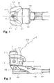
- FIG. 1 shows a plan view of a touring ski binding 100 with a front jaw 1 according to the invention in the holding position.
- the figure on the left is at the ski binding 100 front, while in the figure right at the touring ski binding 100 is back. Accordingly, in the figure on the left also at the front jaw 1 front, while in the figure right at the front jaw 1 is back.
- FIG. 1 From the touring ski binding 100 is in the FIG. 1 only one sole element 101 and the front jaw 1 mounted on the sole element 101 are shown.
- This sole element 101 is pivotable about an axis oriented in the direction of the ski relative to the ski (not shown). Since this axis is arranged below the front jaw 1, it is in the in FIG. 1 shown top view of the toe 1 covered.
- the inventive toe 1 comprises a holding element 2 for holding a ski boot in the region of the tip of the ski boot.
- This holding element 2 is manufactured in one piece and comprises laterally two regions 3.1, 3.2, which reach somewhat rearward, and which can embrace the tip of the ski boot laterally and upwards in order to hold the ski boot in the toe 1.
- the two somewhat reaching backward areas 3.1, 3.2 support the ski boot held in the front jaw 1 side. If the energy of a lateral impact on the ski, touring ski binding 100, or the ski boot exceeds a certain energy, the ski boot held in the toe 1 can be released from the toe 1 by a lateral safety release.
- the holding element 2 is pivotally mounted about a pivot axis 4 and can be pivoted with its two slightly reaching backward areas 3.1, 3.2 to the side.
- This pivot axis 4 extends coaxially to a arranged in the holding element 2 screw 5, the head is accessible from above and therefore in the supervision of FIG. 1 can be seen. If the sole member 101 of the touring ski binding 100 as in the FIG. 1 is horizontally aligned, the pivot axis 4 is vertically aligned. By contrast, when the sole element 101 is pivoted about the axis oriented in the transverse direction, the pivot axis 4 is pivoted in a vertical plane extending in the longitudinal direction of the ski.
- FIG. 2 also shows the ski touring binding 100 with the inventive toe 1.
- FIG. 1 show the FIG. 2 however, a side view of Touring ski binding 100.
- a ski boot 200 held in touring ski binding 100 is shown with a dashed line.
- the dotted line also extends through the rearwardly extending portion 3.1 of the support member 2, which is located in front of the ski boot 200 in the side view shown.
- the two stops 6.1 have a substantially square cross section, but the side edges of the cross section are slightly bent.
- the crosshead of a spindle 7 can be seen, which is aligned horizontally in the direction of the ski by the two stops 6.1 and thus extends through the holding element 2 of the front jaw 1.
- FIG. 3 shows a cross-section oriented in the direction of the ski through the front jaw 1 mounted on the sole element 101.
- This cross-section runs along the pivot axis 4 and is thus aligned perpendicular to the sole element 101. Since it is assumed below that the sole element 101 is aligned in parallel with the ski, orientation indications used such as "top”, “bottom”, “vertical”, “rear” or “front” coincide with the input reference system of the (fictitious) ski.
- the front jaw 1 has a base element 8 which is mounted on the sole element 101.
- the base element 8 is slightly embedded in the sole element 101.
- the axis 102 about which the sole element 101 can be pivoted, extends partly through the sole element 101 and partly through the base element 8, whereby the base element 8 is fastened to the sole element 101.
- the base element 8 comprises a pin 9 pointing vertically upwards.
- This pin 9 extends coaxially with the pivot axis 4 and thus also coaxially with the screw 5.
- the retaining element 2 is pivotably mounted on the pin 9 about the pivot axis 4.
- the pin 9 and the bearing of the pin 9 in the holding element 2 together form a radial bearing 13.
- the toe 1 can be adjusted by the height adjustment of the support member 2 to different ski boots with different thicknesses soles.
- the spindle 7 is aligned horizontally in the direction of the cross-machine direction by the two stops 6.1, 6.2 and thus by the holding element 2.
- the spindle 7 also extends through an opening 10 in the journal 9 oriented horizontally in the direction of the ski. Therefore, when the holding member 2 is adjusted by adjusting the screw 5 in its height relative to the base member 8 and the pin 9, the spindle 7 is moved in the opening 10 in the pin 9 in the vertical direction downwards or upwards.
- the spindle 7 has in the region of its two ends depending on a counter-rotating thread on which each one of the two stops 6.1, 6.2 is mounted. Since the two stops 6.1, 6.2 seen in Skiquerides have a substantially square cross section, they do not rotate when the spindle 7 is rotated in the support member 2 about its longitudinal axis. Therefore, the two stops 6.1, 6.2 can be moved by turning the spindle 7 toward and away from each other.
- the spindle may also have at its one end a fixed head, which forms a first stop, and in the region of its other end have a thread on which a second stop is mounted.
- the head of the spindle should be rotatable in the holding element, while the second stop should not be rotatable, when the spindle is rotated about its longitudinal axis.
- This also allows the two stops to be moved towards and away from each other by turning the spindle. Therefore, in both cases by turning the spindle 7, a distance between the stops 6.1, 6.2 can be adjusted, whereby the energy can be adjusted, which can be absorbed by the toe jaw 1 in a lateral shock until it comes to a lateral safety release.
- a stub element 12.1, 12.2 is arranged on each side of the pin 9. These two stub elements 12.1, 12.2 each have an opening through which the spindle 7 is guided.
- the two stub elements 12.1, 12.2 are mounted movably along the spindle 7. Further, in each case a spring 11.1, 11.2 is arranged on each stop 6.1, 6.2 between the respective stop 6.1, 6.2 and the stub element 12.1, 12.2 on the respective side of the pin 9. These springs 11.1, 11.2 are each supported with a first end opposite the respective stop 6.1, 6.2. In addition, they are each supported with a second end opposite the stub element 12.1, 12.2, which is located on its side of the pin 9.
- the spindle 7 Since the spindle 7 is movable relative to the holding element 2 in the transverse direction and since the two stops 6.1, 6.2 are also movable relative to the holding element 2 in the transverse direction, the spindle 7 moves with the two stops 6.1, 6.2 in such a way that the force generated by the two springs 11.1, 11.2 is exercised, uniformly distributed to the two springs 11.1, 11.2 and the two Stoss institute 12.1, 12.2.
- the two mating elements 12.1, 12.2 are coupled to one another via the spindle 7 serving as the coupling element, so that they press against the pin 9 with the same force.
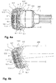
- FIGS. 4a and 4b each show a plan view of a horizontal cross section through the front jaw 1, which runs along the longitudinal axis of the spindle 7.
- FIG. 1 is in the FIGS. 4a and 4b 100 on the left at the touring binding 100, while in the figures on the right at the touring binding 100 is behind. Accordingly, in the figures left on the front jaw 1 front, while in the figures right at the front jaw 1 back.
- FIG. 4a is the toe 1 as already in the FIG. 1 shown as part of touring ski binding 100.
- the retaining element is also as in the FIG. 4a in the stop position.
- the outline of the ski boot 200 held in the toe 1 is shown by a dashed line.
- the ski boot 200 is also shown.
- the holding element 2 is in the FIG. 4b not in the holding position, but in a laterally pivoted away from the holding position position.
- the ski boot 200 is also shown moved away from the center of the ski. As a result, the operation of the front jaw 1 is illustrated with a lateral safety release.
- the spindle 7 is guided in Skiquerides through the opening 10 in the pin 9.
- the two mating elements 12.1, 12.2 are coupled to each other via the spindle 7, so that they press against the pin 9 with a substantially equal force.
- the two stub elements 12.1, 12.2, viewed in the longitudinal direction of the ski have a vertically aligned, flat surface in front of and behind the spindle 7.
- the pin 9 in turn has seen in the ski longitudinal direction on both sides before and behind the opening on a flat surface, which is aligned vertically in the ski longitudinal direction.
- the cross section of the pin 9 is not continuous circular, but has seen through the bilaterally arranged flat surfaces seen in the ski longitudinal direction on both sides each have a flat, flat area.
- a lateral safety release can occur if a lateral impact on the ski, touring ski binding 100 or ski boot 200 exceeds a certain energy.
- the ski boot 200 presses laterally against the lying in the direction of movement of the ski boot 200, slightly reaching back area 3.1, 3.2 of the holding element 2 and against the corresponding roller 14.1, 14.2.
- the holding element 2 is pivoted about the pivot axis 4. The farther the holding element 2 is pivoted, the further the flat surfaces of the stub elements 12.1, 12.2 and the pin 9 are tilted and the further the two stub elements 12.1, 12.2 are moved apart in comparison to the holding position.
- the ski boot 200 can roll on the roller 14.1, 14.2 located in the direction of movement of the ski boot 200 and detach laterally from the toe 1.
- the energy that can be absorbed by the toe piece 1 until the ski boot 200 is released from the toe piece 1 can be adjusted.
- the two stops 6.1, 6.2 moved by turning the spindle 7 toward or away from each other, whereby the two springs 11.1, 11.2 are biased more or less strongly.
- FIG. 5 shows a vertical in the ski center in the ski longitudinal direction extending cross section through the ski binding 100 with the inventive toe 1. Again left in the figure in the touring ski binding 100 front, while right in the figure at the touring ski binding 100 is back. Accordingly, turn left in the figure at the toe 1 front, while right in the figure at the toe 1 back.
- the cross-sectional view runs through the base element 8 and shows how the pin 9 is mounted in the holding element 2.
- the cross section runs along the pivot axis 4 and the screw 5 and cuts the spindle 7 and the axis 102 about which the sole element 101 of the touring ski binding can be pivoted, at a right angle.
- the Figures 6a and 6b each show a schematic representation of a plan view of another inventive toe 51.
- the front jaw 51 comprises a holding element 52 which is pivotable about a pivot axis 54 is pivotally mounted on a base member 58.
- This base element 58 may for example be mounted on a ski. But it can also be mounted on a sole element of a touring ski binding, for example, which is pivotable about an axis oriented horizontally in the ski direction.
- the base member 58 includes a vertically upwardly facing pin 59.
- This pin 59 has on its seen in the longitudinal direction of the front side a flat, flat portion whose surface is vertically aligned in the cross-machine direction. Otherwise, the cross section of the pin 59 is circular.
- the pin 59 together with a counterpart of the holding member 52, a radial bearing 63. Due to this radial bearing 63, the holding member 52 relative to the base member 58 is pivotally mounted about the pivot axis 54. In this case, the holding element 52 is not movable in the radial direction to the pivot axis 54 relative to the base element 58 due to the radial bearing 63 and can only be pivoted about the pivot axis 54.
- a coupling element 57 is slidably mounted in the ski longitudinal direction.
- This coupling element 57 has the shape of a rectangular plate, which is aligned with its main surfaces in parallel. In its center, the coupling element 57 has an opening through which the pin 59 is guided.
- a front edge 56 of the opening in the coupling member 57 is flattened and lies flat on the flat, flat portion of the pin 59 when the holding member 52 is in a holding position.
- a piston 62 In front of the rear edge of the opening in the coupling element 57 is a piston 62, which is pressed by a spring 61 away from the rear edge of the opening to the pin 59. As a result, the pin 59 is clamped between the front edge 56 of the opening and the piston 62.
- the front edge 56 of the opening and the piston 62 each form a stub element. Since the coupling member 57 is movable radially of the radial bearing 63, it can distribute the force caused by the spring 61 on the front edge 56 of the opening in the coupling member 57 and the piston 62, so that the front edge 56 and the piston 62 with a substantially same Force against the radial bearing 63 are pressed.
- the coupling element 57 also pivoted. As a result, both the flattened front edge 56 of the opening in the coupling element 57 and the piston 62 are pivoted together. Since the flattened front edge 56 is thereby tilted relative to the flat, flattened portion of the pin 59, the coupling member 57 is pushed in the radial direction relative to the pin 59 and thus with respect to the pivot axis 54 and against the holding member 52 to the front. Thus, the rear edge of the opening in the coupling member 57 is pushed forward in the direction of pin 59, whereby the spring 61 is compressed.
- the front jaw 51 can absorb a certain amount of energy during a lateral pivoting movement of the holding element 52 about the pivot axis 54 until a lateral safety release occurs.
- the absorbable energy can be adjusted by the bias of the spring 61. Due to the interplay of the flat, flattened portion of the pin 59 and the flattened front edge 56, the flat, flattened portion of the pin 59 forms a positioning structure, while the flattened front edge 56 forms a counter-structure to the positioning structure.
- first inventive toe 1 can also when in the Figures 6a and 6b shown toe 51 a height of the holding member 52 are adjusted relative to the base member 58.
- a mechanism is also provided with a screw, as it is explained in detail for the first inventive toe 1. This mechanism, however, is in the Figures 6a and 6b can not be seen.
- the coupling element can be formed in the second embodiment, for example, as a spindle. It may be aligned in the longitudinal direction of the ski or in the direction of the ski. In addition, it may be movably mounted in the ski longitudinal direction or in the ski direction. The same is true for the spindle according to the first embodiment, which can be formed as the coupling element according to the second embodiment.
- the front jaw as described may include two stucco elements or even more than two stamper elements. Moreover, in both embodiments, only one or two of the stub elements can be movably mounted along the coupling element.
- the coupling element is mounted on the holding element.
- the coupling element can also be mounted on the base element.
- such a modification may, for example, be such that the coupling element is movably arranged in the longitudinal direction of the ski on the base element, while the pin is arranged on the retaining element.
- the pin is pivotally mounted about the pivot axis in a counterpart arranged on the base element. Therefore, in this embodiment, when the holding member is pivoted about the pivot axis, the flat flattened portion on the front side of the pin is also pivoted with respect to the base member.
- this area is tilted relative to the flat, front edge of the opening in the coupling element, whereby the coupling element is pushed forward relative to the base element.
- the spring is also tensioned, whereby an energy absorption is made possible by the toe.
- the two stops, springs, stamper and the spindle can be arranged on the base element. If the pin is not arranged on the base element, but on the holding element and is pivotally mounted in a counterpart on the base element about the pivot axis, so the push elements can press against the pin.
- both the two stops, the springs, the Stossetti, the spindle and the pin are mounted on the base element, so the two Stossrion can press against the counterpart on the holding element, in which the pin is rotatably mounted.
- the counterpart on the holding element should have a shape such that the distance is increased by at least one of the two Stoss institute to the pivot axis when the holding element is pivoted away from the holding position.
- the stub elements and the element of the radial bearing, with which cooperate the Stossiata can be shaped differently. It is not necessary that one or both of the male members and the corresponding member of the radial bearing have planar surfaces as in the above-described embodiments, which are mutually tilted when the retainer is moved away from the holding position.
- the one or both stub elements and the corresponding element of the radial bearing can for example also have a bulge and indentation. What is important about their shape is that at least one of the mating elements is moved away from the axis of rotation when the holding element is pivoted away from the holding position. By this movement of the or the push elements one or more springs or elastic elements can be compressed or pulled apart. As a result, energy can be absorbed by the toe piece during a pivoting movement of the retaining element.
- a mechanism which allows a safety release in the reverse direction.
- such a mechanism may for example be given by the fact that the holding element is rotatably mounted not only about the pivot axis on the base element, but also slightly about a horizontal, substantially aligned in the cross direction axis. This can be achieved, for example, by virtue of the fact that the counterpart, with which the holding element is mounted on the pin, allows the holding element to rock about a horizontal axis which is oriented substantially in the direction of the ski.
- the mating elements should be designed such that they hold the holding element in the holding position in a predetermined orientation about the horizontal, aligned substantially in the direction of the cross axis.
- the support member When an upward force acts on the ski boot or a downward force acts on the toe or ski, the support member can be pivoted about the horizontal, substantially cross-machine directional axis until the ski boot is released from the toe. During this pivoting movement The two jaw elements should be pressed apart so that the front jaw can absorb energy until it comes to a safety release in the reverse direction.
- the two laterally arranged Stoss comprise not only in the ski longitudinal direction aligned, have vertical, flat surfaces, but also surround the pin at the front and rear something to support the pin front and rear.
- the two die elements are pressed apart when the holding element with the two die elements is pivoted about the horizontal, oriented substantially in the direction of the cross grain axis with respect to the pin.
- no adjustment of the two Stossieri is required, since they are forced apart due to their vertical extent, when the holding element is pivoted about a horizontal, aligned substantially in the direction of the cross axis relative to the pin.
- a front jaw is provided which allows both an optimally controlled lateral safety release and permits a compact design.
Landscapes
- Footwear And Its Accessory, Manufacturing Method And Apparatuses (AREA)
Abstract
Description
- Die Erfindung betrifft einen Vorderbacken für eine Skibindung. Dieser Vorderbacken umfasst ein Sockelelement, ein Radiallager mit einer Schwenkachse, welche in einer im Wesentlichen vertikal ausgerichteten, in Skilängsrichtung verlaufenden Ebene angeordnet ist, ein elastisches Element, wenigstens zwei Stosselemente, welche um das Radiallager angeordnet sind, und ein Halteelement zum Halten eines Skischuhs im Bereich einer Skischuhspitze. Dabei ist das Halteelement durch das Radiallager um die Schwenkachse schwenkbar am Sockelelement gelagert und weist eine Halteposition zum Halten des Skischuhs auf. Zudem ist das Halteelement ausgehend von der Halteposition in Skiquerrichtung auf beide Seiten schwenkbar, wodurch eine seitliche Sicherheitsauslösung ermöglicht wird.
- Zum eingangs erwähnten technischen Gebiet gehörende Vorderbacken sind bekannt. Ein Beispiel eines solchen Vorderbackens ist in der
DE 29 49 866 A1 der Etablissements François Salomon et Fils beschrieben. Dieser Vorderbacken umfasst ein Gehäuse, in dessen hinteren Bereich ein Zwischenstück angeordnet ist. An diesem Zwischenstück ist ein Halteteil zum Halten des vorderen Endes einer Skischuhsohle angebracht. Das Gehäuse weist in seinem vorderen Bereich eine Bohrung auf, in welcher ein Kolben in Längsrichtung des Gehäuses verschiebbar geführt und durch eine Feder mit einer nach hinten gerichteten Kraft beaufschlagt ist. Weiter weist das Gehäuse in einem zentralen Bereich eine nach unten offene Ausnehmung auf. In diese Ausnehmung greift ein Anlageteil ein, welches von einer an einem Ski befestigbaren Basisplatte nach oben zeigt. Der Kolben drückt mit einer Fläche von vorne nach hinten gerichtet gegen eine vordere Fläche des Anlageteils, sodass das Anlageteil gegen das Zwischenstück gedrückt wird. Daher liegt das Zwischenstück auf der breiten hinteren Seite des Anlageteils auf, wenn sich der Vorderbacken in einer Haltestellung zum Halten eines Skischuhs befindet. Ausgehend von dieser Haltestellung kann das Gehäuse bei einer seitlichen Sicherheitsauslösung zusammen mit dem Halteteil um das Anlageteil geschwenkt werden. Bei einer derartigen Schwenkbewegung wird auch das Zwischenstück gegenüber der hinteren Seite des Anlageteils geschwenkt, sodass es am seitlichen Rand der breiten hinteren Seite des Anlageteils abgestützt etwas nach hinten bewegt wird. Dies führt dazu, dass auch das Gehäuse und das Halteteil etwas in Skilängsrichtung gesehen nach hinten bewegt werden. Zudem wird mit der Schwenkbewegung auch der im Gehäuse angeordnete Kolben gegenüber dem Anlageteil verschwenkt. Dies führt dazu, dass die Fläche des Kolbens gegenüber der nach vorne ausgerichteten, vorderen Fläche des Anlageteils verkippt wird. Dadurch wird der Kolben im Gehäuse gegen die Kraft der Feder nach vorne bewegt. Entsprechend kann der Vorderbacken bei einem Stoss auf einen im Vorderbacken gehaltenen Skischuh eine Energie aufnehmen, bis es zu einer seitlichen Sicherheitsauslösung kommt. - Der Nachteil dieses Vorderbackens ist, dass die vom Vorderbacken aufnehmbare Energie nicht nur vom zurückgelegten Weg des Kolbens und der Kraft der Feder, sondern auch von äusseren Krafteinflüssen auf das Halteteil und das Gehäuse abhängt. Dies kommt daher, dass das Anlageteil zwischen dem Zwischenstück und dem Kolben eingeklemmt ist und dass das Halteteil, das Zwischenstück und das Gehäuse gegenüber dem Anlageteil in Skilängsrichtung bewegbar sind. Dadurch ändert eine nach vorne oder nach hinten gerichtete Krafteinwirkung auf das Halteteil oder das Gehäuse die vom Vorderbacken aufnehmbare Energie. Hinzu kommt, dass das Halteteil, das Zwischenstück und das Gehäuse bei einer Drehbewegung um das Anlageteil etwas nach hinten bewegt werden, wodurch das Halteteil nach hinten gegen den in der Skibindung gehaltenen Skischuh drückt und der Skischuh entsprechend eine nach vorne gerichtete Kraft auf das Halteteil bewirkt. Dadurch wird durch den in der Skibindung gehaltenen Skischuh auch ohne weitere Krafteinflüsse die vom Vorderbacken aufnehmbare Energie beeinflusst.
- Ein Vorderbacken, welcher diesen Nachteil behebt, ist in der
US 4,494,769 von Ste Look beschrieben. Dieser Vorderbacken umfasst ein Halteteil zum Halten des vorderen Endes einer Skischuhsohle, welches um eine vertikale Achse schwenkbar an einem Basisteil gelagert ist. In einem vorderen Bereich vor der vertikalen Achse weist dieses Halteteil eine ebene Fläche auf. Ein am Basisteil gelagerter und in Skilängsrichtung verschiebbarer Kolben, welcher durch zwei Federn mit einer von vorne nach hinten gerichteten Kraft beaufschlagt ist, drückt von vorne gegen diese ebene Fläche im vorderen Bereich des Halteteils. Dadurch wird das Halteteil in einer Haltestellung gehalten, in welcher die ebene Fläche im vorderen Bereich des Halteteils parallel zur Stossfläche des Kolbens ausgerichtet ist. Bei einem seitlichen Stoss auf den Skischuh wirkt ein Drehmoment auf das Halteteil, wodurch das Halteteil um die vertikale Achse geschwenkt wird. Dies führt dazu, dass die Fläche im vorderen Bereich des Halteteils gegenüber der Stossfläche des Kolbens verkippt wird. Dadurch wird der Kolben gegen die Federkraft nach hinten bewegt. Die Energie, die bei einem solchen Stoss aufgenommen wird, bis der Skischuh aus der Bindung gelöst wird, ist durch den vom Kolben zurückgelegten Weg und die Kraft der beiden Federn definiert. - Dieser Vorderbacken ermöglicht zwar eine gut kontrollierte seitliche Sicherheitsauslösung. Er hat aber den Nachteil, dass die Konstruktion sehr voluminös ist.
- Wie aus der Beschreibung dieser bekannten Vorderbacken hervorgeht, wird für die Beschreibung von Skibindungen als Referenzsystem oft ein (fiktiver) Ski verwendet. Dabei wird jeweils angenommen, dass die Bindung auf diesem Ski montiert sei. Diese Gewohnheit wird im vorliegenden Text übernommen. So bedeutet der Begriff "Skilängsrichtung" entlang der Ausrichtung der Längsachse des Skis. Ähnlich bedeutet "skiparallel" für ein längliches Objekt entlang der Längsachse des Skis ausgerichtet. Für ein flächiges Objekt hingegen bedeutet der Begriff "skiparallel" parallel zur Gleitfläche des Skis ausgerichtet. Weiter ist mit dem Begriff "Skiquerrichtung" eine Richtung quer zur Skilängsrichtung gemeint, welche aber nicht genau rechtwinklig zur Längsachse des Skis orientiert sein muss. Ihre Ausrichtung kann auch etwas von einem rechten Winkel abweichen. Der Begriff "Skimitte" wiederum bedeutet, in Skiquerrichtung gesehen, eine Mitte des Skis, während der Begriff "skifest" nicht beweglich gegenüber dem Ski bedeutet. Zudem ist zu beachten, dass auch Begriffe, welche das Wort "Ski" nicht enthalten, auf das Referenzsystem des (fiktiven) Skis Bezug nehmen. So beziehen sich die Begriffe "vorne", "hinten", "oben", "unten" sowie "seitlich" auf "vorne", "hinten", "oben", "unten" sowie "seitlich" des Skis. Genauso beziehen sich auch Begriffe wie "horizontal" und "vertikal" auf den Ski, wobei "horizontal" in einer skiparallelen Ebene liegend und "vertikal" senkrecht zu dieser Ebene ausgerichtet bedeutet.
- Aufgabe der Erfindung ist es, ein dem eingangs genannten technischen Gebiet zugehörender Vorderbacken zu schaffen, welcher sowohl eine optimal kontrollierte seitliche Sicherheitsauslösung ermöglicht als auch eine kompakte Bauweise zulässt.
- Die Lösung der Aufgabe ist durch die Merkmale des Anspruchs 1 definiert. Gemäss der Erfindung umfasst der Vorderbacken ein Kopplungselement, welches im Wesentlichen senkrecht zur Schwenkachse ausgerichtet und im Wesentlichen radial zum Radiallager und damit relativ zum Sockelelement und relativ zum Halteelement bewegbar ist. Dabei sind die wenigstens zwei Stosselemente über das Kopplungselement miteinander gekoppelt. Zudem ist ein erstes der wenigstens zwei Stosselemente entlang dem Kopplungselement relativ zum Kopplungselement und radial zum Radiallager bewegbar gelagert und durch das erste elastische Element in Richtung des Radiallagers drückbar, wodurch die über das Kopplungselement miteinander gekoppelten wenigstens zwei Stosselemente mit einer im Wesentlichen gleichen Kraft gegen das Radiallager gedrückt werden. Zudem sind das Radiallager und wenigstens eines der wenigstens zwei Stosselemente derart geformt und wirken derart zusammen, dass das Halteelement durch eine vom ersten elastischen Element erzeugte und durch die Stosselemente gegen das Radiallager wirkende Kraft zur Halteposition drückbar ist.
- Für die erfindungsgemässe Lösung sind verschiedene Ausführungen des Radiallagers möglich. So kann das Radiallager beispielsweise ein in einem Zapfenlager gelagerter Zapfen sein. Es kann sich aber beispielsweise auch um ein Kugel- oder Rollenlager oder um ein andersartig ausgebildetes Radiallager handeln. Wichtig ist einzig, dass das Radiallager eine Schwenkbewegung des Halteelements relativ zum Sockelelement um die Schwenkachse erlaubt und eine Translationsbewegung des Halteelements relativ zum Sockelelement senkrecht zur Schwenkachse unterbindet.
- Weiter können für die erfindungsgemässe Lösung die wenigstens zwei Stosselemente auf verschiedene Arten um das Radiallager angeordnet sein. Zudem können die wenigstens zwei Stosselemente direkt oder indirekt über ein oder mehrere andere Element gegen das Radiallager gedrückt werden. Dabei kann das erste der wenigstens zwei Stosselemente, welches entlang dem Kopplungselement relativ zum Kopplungselement und radial zum Radiallager bewegbar gelagert ist, beispielsweise am Kopplungselement bewegbar gelagert sein. Dieses erste der wenigstens zwei Stosselemente kann aber auch nicht am Kopplungselement, sondern an einem oder mehreren anderen Elementen des Vorderbackens bewegbar gelagert sein, sodass es entlang dem Kopplungselement radial zum Radiallager bewegbar ist. So kann es beispielsweise am Halteelement bewegbar gelagert sein, sodass es entlang dem Kopplungselement radial zum Radiallager bewegbar ist. Beispielsweise kann das erste der wenigstens zwei Stosselemente aber auch am Sockelelement bewegbar gelagert sein, sodass es entlang dem Kopplungselement radial zum Radiallager bewegbar ist. Das erste der wenigstens zwei Stosselemente kann aber auch am Kopplungselement, am Halteelement oder am Sockelelement und auch an einem oder mehreren weiteren Elementen des Vorderbackens bewegbar gelagert sein, sodass es entlang dem Kopplungselement radial zum Radiallager bewegbar ist.
- Weiter kann das erste der wenigstens zwei Stosselemente entlang einem linearen Weg bewegbar am Kopplungselement oder an einem oder mehreren anderen Elementen des Vorderbackens gelagert sein. Dieser lineare Weg kann sowohl gerade als auch gekrümmt sein. Dabei ist er jedoch zumindest teilweise entlang dem Kopplungselement radial zum Radiallager und damit zur Schwenkachse ausgerichtet. Das erste der wenigstens zwei Stosselemente kann aber auch um eine physische oder eine geometrische Achse schwenkbar am Kopplungselement oder an einem oder mehreren anderen Elementen des Vorderbackens gelagert sein. In diesem Fall ist die physische oder geometrische Achse derart angeordnet, dass eine Schwenkbewegung des ersten der wenigstens zwei Stosselemente dazu führt, dass ein von der physischen oder geometrischen Achse entfernter Bereich des ersten der wenigstens zwei Stosselemente entlang dem Kopplungselement radial zum Radiallager bewegbar ist. Es ist aber auch möglich, dass das erste der wenigstens zwei Stosselemente sowohl entlang einem linearen Weg als auch um eine physische oder geometrische Achse schwenkbar am Kopplungselement oder an einem anderen Element des Vorderbackens bewegbar gelagert ist.
- Unabhängig davon kann das erste der wenigstens zwei Stosselemente, welches entlang dem Kopplungselement radial zum Radiallager bewegbar gelagert ist, eines des wenigstens einen der wenigstens zwei Stosselemente sein, welches derart geformt ist, dass es derart mit dem Radiallager zusammenwirkt, dass das Halteelement durch eine vom ersten elastischen Element erzeugte und durch die Stosselemente gegen das Radiallager wirkende Kraft zur Halteposition drückbar ist. Alternativ dazu kann das erste der wenigstens zwei Stosselemente aber auch nicht derart geformt sein, dass es derart mit dem Radiallager zusammenwirkt, dass das Halteelement durch eine vom ersten elastischen Element erzeugte und durch die Stosselemente gegen das Radiallager wirkende Kraft zur Halteposition drückbar ist. Entsprechend unterscheidet sich in diesem Fall das erste der wenigstens zwei Stosselemente vom wenigstens einen der wenigstens zwei Stosselemente, welches derart geformt ist, dass es derart mit dem Radiallager zusammenwirkt, dass das Halteelement durch eine vom ersten elastischen Element erzeugte und durch die Stosselemente gegen das Radiallager wirkende Kraft zur Halteposition drückbar ist.
- Unabhängig von der Ausführung des Radiallagers und der wenigstens zwei Stosselemente sind für die erfindungsgemässe Lösung verschiedene Ausführungen des Kopplungselements möglich. So kann das Kopplungselement beispielsweise länglich oder flächig ausgebildet sein. In beiden Fällen ist das Kopplungselement im Wesentlichen senkrecht zur Schwenkachse ausgerichtet. Falls das Kopplungselement länglich ausgebildet ist, so bedeutet dies, dass eine Längsachse des Kopplungselements im Wesentlichen senkrecht zur Schwenkachse ausgerichtet ist. Zudem ist bei einer länglichen Ausführung des Kopplungselements das erste der wenigstens zwei Stosselemente, welches entlang dem Kopplungselement radial zur Schwenkachse bewegbar gelagert ist, entlang der Längsachse des Kopplungselements bewegbar. Wenn das Kopplungselement hingegen flächig ausgebildet ist, bedeutet dies, dass eine Ebene, welche durch das flächige Kopplungselement definiert ist, im Wesentlichen senkrecht zur Schwenkachse ausgerichtet ist. Dabei ist das erste der wenigstens zwei Stosselemente, welches entlang dem Kopplungselement radial zur Schwenkachse bewegbar gelagert ist, entlang der Ebene, welche durch das flächige Kopplungselement definiert ist, bewegbar.
- Unabhängig von der Ausführung des Radiallagers, der wenigstens zwei Stosselemente und des Kopplungselements sind verschiedene Ausführungsformen des ersten elastischen Elements möglich. So kann das erste elastische Element beispielsweise einstückig oder mehrstückig gefertigt sein. Falls das erste elastische Element mehrstückig gefertigt ist, besteht beispielsweise die Möglichkeit, dass es nur ein elastisches Teil zur Erzeugung der Kraft umfasst, durch welche das erste der wenigstens zwei Stosselemente in Richtung des Radiallagers drückbar ist. Ein mehrstückig gefertigtes erstes elastisches Element kann aber auch mehrere elastische Teile umfassen, welche parallel oder seriell angeordnet sein können, um die Kraft zu erzeugen, durch welche das erste der wenigstens zwei Stosselemente in Richtung des Radiallagers drückbar ist. Unabhängig von der Anzahl elastischer Teile und unabhängig davon, ob das elastische Element einstückig oder mehrstückig gefertigt ist, kann es sich bei jedem der elastischen Teile beispielsweise um eine Feder, eine Stahlfeder, oder aber auch um ein aus einem elastischen Material wie beispielsweise Gummi gefertigten Element handeln. Zudem kann unabhängig von der Anzahl elastischer Teile und unabhängig davon, ob das elastische Element einstückig oder mehrstückig gefertigt ist, das erste elastische Element beispielsweise derart im Vorderbacken vorgespannt sein, dass es zwei seiner Enden durch eine Zugkraft zueinander hin zieht. Genauso kann das elastische Element aber beispielsweise auch derart vorgespannt sein, dass es zwei seiner Enden durch eine Stosskraft voneinander weg drückt.
- Ein erster Vorteil der erfindungsgemässen Lösung ist, dass eine optimal kontrollierte seitliche Sicherheitsauslösung ermöglicht wird. Dies wird einerseits dadurch erreicht, dass das Halteelement durch das Radiallager um die Schwenkachse schwenkbar am Sockelelement gelagert ist und somit nicht radial zur Schwenkachse bewegbar ist. Andererseits wird die optimal kontrollierte Sicherheitsauslösung dadurch erreicht, dass das Kopplungselement im Wesentlichen radial zum Radiallager bewegbar ist und dass die wenigstens zwei Stosselemente über das Kopplungselement miteinander gekoppelt sind, wobei ein erstes der wenigstens zwei Stosselemente entlang dem Kopplungselement relativ zum Kopplungselement und radial zum Radiallager bewegbar gelagert ist und durch das erste elastische Element in Richtung des Radiallagers drückbar ist, wodurch die über das Kopplungselement miteinander gekoppelten wenigstens zwei Stosselemente mit einer im Wesentlichen gleichen Kraft gegen das Radiallager drücken. Wenn daher eine äussere Kraft auf das Halteelement wirkt, ist das Halteelement durch das Radiallager sicher am Sockelelement gelagert, während das Kopplungselement und die wenigstens zwei Stosselemente von dieser Krafteinwirkung nicht beeinflusst werden, da sie relativ zum Radiallager bewegbar sind. Entsprechend ist die Energie, welche vom Vorderbacken aufgenommen werden kann, bis es zu einer seitlichen Sicherheitsauslösung kommt, weitestgehend unabhängig von äusseren Krafteinflüssen. Somit ermöglicht der erfindungsgemässe Vorderbacken eine optimal kontrollierbare Sicherheitsauslösung. Dieser Vorteil wird unabhängig davon erreicht, ob der Vorderbacken in einer Alpinskibindung oder in einer Tourenskibindung verwendet wird.
- Ein zweiter Vorteil der erfindungsgemässen Lösung ist, dass eine kompakte Konstruktion des Vorderbackens ermöglicht wird, weil die wenigstens zwei Stosselemente um das Radiallager angeordnet sind und somit die Mechanik, welche eine seitliche Sicherheitsauslösung um das Radiallager ermöglicht, in kompakter Weise um das Radiallager angeordnet werden kann.
- Um diese beiden Vorteile zu erreichen, spielt es keine Rolle, ob die wenigstens zwei Stosselemente zusammen mit dem Halteelement gegenüber dem Sockelelement um die Schwenkachse schwenkbar sind, wenn das Halteelement um die Schwenkachse geschwenkt wird, oder ob die wenigstens zwei Stosselemente in einem gleichen Winkel zur Schwenkachse wie das Sockelelement bleiben, wenn das Halteelement um die Schwenkachse geschwenkt wird.
- In einer bevorzugten Ausführungsform umfasst der Vorderbacken für eine Skibindung ein Sockelelement, ein Radiallager mit einer Schwenkachse, welche in einer im Wesentlichen vertikal ausgerichteten, in Skilängsrichtung verlaufenden Ebene angeordnet ist, ein elastisches Element, wenigstens zwei Stosselemente, welche um das Radiallager angeordnet sind, und ein Halteelement zum Halten eines Skischuhs im Bereich einer Skischuhspitze. Dabei ist das Halteelement durch das Radiallager um die Schwenkachse schwenkbar am Sockelelement gelagert und weist eine Halteposition zum Halten des Skischuhs auf. Zudem ist das Halteelement ausgehend von der Halteposition in Skiquerrichtung auf beide Seiten schwenkbar, wodurch eine seitliche Sicherheitsauslösung ermöglicht wird. In dieser bevorzugten Ausführungsform umfasst der Vorderbacken ein Kopplungselement, welches im Wesentlichen senkrecht zur Schwenkachse ausgerichtet und im Wesentlichen radial zum Radiallager und damit relativ zum Sockelelement und relativ zum Halteelement bewegbar ist. Dabei sind die wenigstens zwei Stosselemente über das Kopplungselement miteinander gekoppelt, wobei ein erstes der wenigstens zwei Stosselemente entlang dem Kopplungselement relativ zum Kopplungselement und radial zur Schwenkachse bewegbar gelagert ist und durch das erste elastische Element in Richtung des Radiallagers gedrückt wird. Dadurch werden die über das Kopplungselement miteinander gekoppelten wenigstens zwei Stosselemente mit einer im Wesentlichen gleichen Kraft gegen das Radiallager gedrückt. Weiter weist das Radiallager wenigstens eine Positionierstruktur auf und wenigstens eines der Stosselemente weist eine Gegenstruktur zur wenigstens einen Positionierstruktur auf. Wenn sich das Halteelement in der Halteposition befindet, befindet sich das wenigstens eine Stosselement mit seiner Gegenstruktur auf der entsprechenden wenigstens einen Positionierstruktur, wodurch sich die wenigstens zwei Stosselemente in einem ersten Abstand zueinander befinden. Wenn das Halteelement von der Halteposition wegbewegt ist, ist das wenigstens eine Stosselement mit seiner Gegenstruktur von der entsprechenden wenigstens einen Positionierstruktur wegbewegt, wodurch sich die wenigstens zwei Stosselemente in einem Abstand zueinander befinden, welcher grösser als der erste Abstand ist, sodass das Halteelement durch eine vom ersten elastischen Element bewirkte Kraft zur Halteposition gedrückt wird. Je weiter dabei das Halteelement von der Halteposition weg bewegt ist, desto grösser ist vorzugsweise der Abstand zwischen den wenigstens zwei Stosselementen. Dies hat den Vorteil, dass die vom ersten elastischen Element bewirkte Kraft optimal in eine rücktreibende Kraft umgelenkt wird, welche das Halteelement zur Halteposition hin vorspannt. Dieser Vorteil wird unabhängig davon erreicht, ob nur eines der wenigstens zwei Stosselemente eine Gegenstruktur aufweist oder ob mehr als eines der wenigstens zwei Stosselemente eine Gegenstruktur aufweist. Falls nur eines der wenigstens zwei Stosselemente eine Gegenstruktur aufweist, so wird der Vorteil unabhängig davon erreicht, welches der wenigstens zwei Stosselemente diese Gegenstruktur aufweist.
- Falls der Vorderbacken in dieser bevorzugten Ausführungsform mehr als eine der wenigstens einen Positionierstruktur umfasst, so sind diese Positionierstrukturen dadurch räumlich voneinander abgegrenzt, dass sich gleichzeitig auf jeder der Positionierstrukturen je ein Stosselement mit seiner Gegenstruktur befinden kann. Dabei kann ein Übergang von einer Positionierstruktur zu einer benachbarten Positionierstruktur aber kontinuierlich, d.h. ohne strukturelle Abtrennung, ausgebildet sein. Ein Übergang von einer Positionierstruktur zu einer benachbarten Positionierstruktur kann aber auch durch eine strukturelle Abtrennung ausgebildet sein. Entsprechend ist es auch unerheblich, ob die Positionierstrukturen gemeinsam aus einem einzigen Stück gefertigt sind, oder ob jede der Positionierstrukturen als separates Stück gefertigt ist.
- In der bevorzugten Ausführungsform kann die wenigstens eine Positionierstruktur beispielsweise als Einbuchtung oder als Ausbuchtung ausgebildet sein. Falls mehr als eine Positionierstruktur vorhanden ist, kann beispielsweise jede der Positionierstrukturen als Einbuchtung oder als Ausbuchtung ausgebildet sein. Falls es sich bei einer Positionierstruktur um eine Einbuchtung handelt, kann die Gegenstruktur beispielsweise als Ausbuchtung ausgebildet sein. Falls eine Positionierstruktur hingegen als Ausbuchtung ausgebildet ist, kann die Gegenstruktur beispielsweise als Einbuchtung ausgebildet sein. In beiden Fällen kann durch die Form der wenigstens einen Positionierstruktur und der Gegenstruktur eine Führung gebildet werden, welche in Abhängigkeit von der Drehposition des Halteelements um die Schwenkachse einen bestimmten Mindestabstand zwischen dem wenigstens einen Stosselement mit der Gegenstruktur und der Schwenkachse zulässt. Dieser Mindestabstand kann am kleinsten sein, wenn sich das Halteelement in der Halteposition befindet und grösser werden, je weiter das Halteelement von der Halteposition wegbewegt wird. Da die wenigstens zwei Stosselemente über das Kopplungselement miteinander gekoppelt sind und gegen das Radiallager gedrückt werden, kann mit einer derartigen Führung erreicht werden, dass sich die wenigstens zwei Stosselemente in einem ersten Abstand zueinander befinden, wenn sich das Halteelement in der Halteposition befindet, und dass sich die wenigstens zwei Stosselemente in einem Abstand zueinander befinden, welcher grösser als der erste Abstand ist, wenn das Halteelement von der Halteposition weg bewegt ist.
- Die wenigstens eine Positionierstruktur kann aber auch anders als Einbuchtung oder als Ausbuchtung ausgebildet sein. Genauso kann die Gegenstruktur auch anders als Ausbuchtung oder als Einbuchtung ausgebildet sein. So können beispielsweise die wenigstens eine Positionierstruktur und die Gegenstruktur als ebene Fläche ausgebildet sein. Dabei können die wenigstens eine Positionierstruktur und das oder die Stosselemente mit einer Gegenstruktur derart angeordnet sein, dass in der Halteposition des Halteelements die wenigstens eine Positionierstruktur mit seiner ebenen Fläche flächig auf der ebenen Fläche der Gegenstruktur des entsprechenden Stosselements aufliegt. Wenn aus dieser Ausgangslage das Halteelement um die Schwenkachse von der Halteposition weggeschwenkt wird, so wird die ebene Fläche der Gegenstruktur gegenüber der jeweiligen ebenen Fläche der Positionierstruktur verkippt. Dadurch bilden die wenigstens eine Positionierstruktur und die Gegenstruktur eine Führung, welche in Abhängigkeit von der Drehposition des Halteelements um die Schwenkachse einen bestimmten Mindestabstand zwischen dem wenigstens einen Stosselement mit der Gegenstruktur und der Schwenkachse zulässt. Dieser Mindestabstand ist am kleinsten, wenn sich das Halteelement in der Halteposition befindet und wird grösser, je weiter das Halteelement von der Halteposition wegbewegt wird. Da die wenigstens zwei Stosselemente über das Kopplungselement miteinander gekoppelt sind und gegen das Radiallager gedrückt werden, wird mit einer derartigen Führung erreicht, dass sich die wenigstens zwei Stosselemente in einem ersten Abstand zueinander befinden, wenn sich das Halteelement in der Halteposition befindet, und dass sich die wenigstens zwei Stosselemente in einem Abstand zueinander befinden, welcher grösser als der erste Abstand ist, wenn das Halteelement von der Halteposition weg bewegt ist.
- Unabhängig von der Form der wenigstens einen Positionierstruktur und der Gegenstruktur ist die Anzahl der wenigstens einen Positionierstruktur vorzugsweise gleich gross oder grösser als die Anzahl der Stosselemente mit einer Gegenstruktur. Dadurch wird ermöglicht, dass jedes Stosselement mit seiner Gegenstruktur auf einer Positionierstruktur positioniert werden kann. Dies hat den Vorteil, dass die vom ersten elastischen Element erzeugte Kraft optimal genutzt wird, um das Halteelement in die Halteposition zu drücken. Als Alternative dazu besteht aber auch die Möglichkeit, dass die Anzahl der wenigstens einen Positionierstruktur kleiner als die Anzahl der Stosselemente mit einer Gegenstruktur ist. Eine derartige Alternative kann den Vorteil haben, dass die Herstellung des Vorderbackens einfacher ist, da weniger Positionierstrukturen benötigt werden.
- Bevorzugte Ausführungsformen des Vorderbackens können aber auch andersartig ausgebildet sein. Im Folgenden wird anhand von vorteilhaften Merkmalen gezeigt, wie solche andere bevorzugte Ausführungsformen ausgebildet sein können. Selbstverständlich kann aber auch die oben genannte, bevorzugte Ausführungsform mit der wenigstens einen Positionierstruktur und der Gegenstruktur eines oder mehrere dieser vorteilhaften Merkmale umfassen.
- Vorzugsweise umfasst das Halteelement einen starr ausgebildeten Bereich, welcher beidseitig nach hinten reichende Enden aufweist, die derart geformt sind, dass sie in der
- Halteposition des Haltelements einen im Vorderbacken gehaltenen Skischuh seitlich umgreifen. Dies hat den Vorteil, dass das Halteelement in der Halteposition den im Vorderbacken gehaltenen Skischuh mit dem starr ausgebildeten Bereich beidseitig seitlich abstützt. Dadurch kann der Skischuh optimal im Vorderbacken gehalten werden. Dabei spielt es keine Rolle, ob der starr ausgebildete Bereich aus einem einzigen Stück oder aus mehreren, starr miteinander verbundenen Einzelstücken gebildet ist. Unabhängig davon besteht die Möglichkeit, dass am starr ausgebildeten Bereich weitere bewegliche Elemente angeordnet sind. Beispielsweise können am starr ausgebildeten Bereich Rollen gelagert sein, welche bei einer seitlichen Sicherheitsauslösung eine Bewegung des im Vorderbacken gehaltenen Skischuhs vom Vorderbacken weg erleichtern, indem sie einen möglichen Reibungswiderstand zwischen Halteelement und Skischuh reduzieren.
- Alternativ dazu besteht aber auch die Möglichkeit, dass das Halteelement keinen derartigen, starr ausgebildeten Bereich umfasst.
- Vorzugsweise umfasst das Halteelement einen oberen Bereich, welcher etwas nach hinten reicht, um die Sohle eines im Vorderbacken gehaltenen Skischuhs oben zumindest teilweise zu umgreifen. Dies hat den Vorteil, dass der Skischuh optimal im Vorderbacken gehalten werden kann. In einer bevorzugten Variante dazu umfasst ein anderes Element des Vorderbackens als das Halteelement einen Bereich, welcher etwas nach hinten reicht, um die Sohle eines im Vorderbacken gehaltenen Skischuhs oben zumindest teilweise zu umgreifen. Diese Variante hat ebenfalls den Vorteil, dass der Skischuh optimal im Vorderbacken gehalten werden kann. In einer weiteren bevorzugten Variante umfasst sowohl das Halteelement als auch ein oder mehrere weitere Elemente des Vorderbackens je einen Bereich, welcher etwas nach hinten reicht, um die Sohle eines im Vorderbacken gehaltenen Skischuhs zumindest teilweise zu umgreifen.
- Alternativ zu diesen drei Varianten besteht aber auch die Möglichkeit, dass kein Element des Vorderbackens einen Bereich umfasst, welcher etwas nach hinten reicht, um die Sohle eines im Vorderbacken gehaltenen Skischuhs oben zumindest teilweise zu umgreifen. So kann ein Element des Vorderbackens beispielsweise einen nach hinten reichenden Bereich aufweisen, welcher in eine Ausnehmung im Skischuh eingreifen und so den Skischuh nach oben abstützen kann. Durch eine derartige Alternative kann ebenfalls erreicht werden, dass der Skischuh optimal im Vorderbacken gehalten werden kann.
- Vorteilhafterweise ist das Kopplungselement in einer Ebene senkrecht zur Schwenkachse relativ zum Radiallager bewegbar. Dies hat den Vorteil, dass das Kopplungselement nicht nur radial zum Radiallager, sondern in alle Richtungen in der Ebene senkrecht zur Schwenkachse bewegbar ist. Entsprechend kann das Kopplungselement ausgleichend wirken, wenn eine äussere Kraft auf das Halteelement einwirkt. Dadurch wird ermöglicht, dass die wenigstens zwei Stosselement im Wesentlichen unbeeinflusst von der äussern Kraft gegen das Radiallager drücken. Entsprechend wird dadurch eine zuverlässiger kontrollierbare seitliche Sicherheitsauslösung des Vorderbackens ermöglicht.
- Alternativ dazu besteht aber auch die Möglichkeit, dass das Kopplungselement nur im Wesentlichen radial zum Radiallager bewegbar ist.
- Bevorzugt weist das erste elastische Elemente ein erstes und ein zweites Ende auf, wobei das erste Ende des ersten elastischen Elements weiter vom Radiallager entfernt angeordnet ist als das zweite Ende des ersten elastischen Elements, und wobei das erste Ende des ersten elastischen Elements gegenüber dem Kopplungselement abgestützt ist, während das zweite Ende des ersten elastischen Elements gegenüber dem ersten der wenigstens zwei Stosselemente abgestützt ist, welches entlang dem Kopplungselement relativ zum Kopplungselement und radial zum Radiallager bewegbar gelagert ist. Dies hat den Vorteil, dass die vom ersten elastischen Element bewirkte Kraft optimal auf das erste der wenigstens zwei Stosselemente und auf das Kopplungselement übertragen werden kann. Dadurch wird eine optimale Kontrolle einer seitlichen Sicherheitsauslösung ermöglicht. Um diesen Vorteil zu erreichen, ist es unerheblich, ob das erste elastische Element direkt am ersten der wenigstens zwei Stosselemente bzw. direkt am Kopplungselement abgestützt ist, oder ob am ersten der wenigstens zwei Stosselemente oder am Kopplungselement noch ein zwischengeordnetes Stützelement angeordnet ist, gegenüber welchem das erste elastische Element abgestützt ist. Zudem ist es für diesen Vorteil unerheblich, ob das erste elastische Element eine Zugkraft ausübt und die beiden Stellen, an welchen es gegenüber dem Kopplungselement bzw. gegenüber dem Stosselement abgestützt ist, zueinander hin zieht, oder ob das erste elastische Element eine Stosskraft ausübt und die beiden Stellen, an welchen es gegenüber dem Kopplungselement bzw. gegenüber dem Stosselement abgestützt ist, von einander weg stösst.
- In einer bevorzugten Variante dazu ist das erste Ende des ersten elastischen Elements gegenüber einem ersten Ende des Kopplungselements abgestützt. Dabei ist das erste Ende des Kopplungselements ein Längsende des Kopplungselements, falls das Kopplungselements länglich ausgebildet ist. Falls das Kopplungselement hingegen eine im Wesentlichen dreieckige, viereckige oder fünfeckige Form aufweist, so befindet sich das erste Ende des Kopplungselements an einer Ecke des Kopplungselements. Falls das Kopplungselement jedoch sternförmig ausgebildet ist, so befindet sich das erste Ende des Kopplungselements an einer Spitze eines Zackens der Sternform. Falls das Kopplungselement hingegen eine scheibenartige Form mit abgerundetem Rand aufweist, so befindet sich das erste Ende des Kopplungselements an einer Stelle auf dem Rand des Kopplungselements. Unabhängig von der Form des Kopplungselements hat dies den Vorteil, dass der Raum um das Radiallager optimal ausgenutzt werden kann, da das elastische Element vom ersten der wenigstens zwei Stosselemente bis zum ersten Ende des Kopplungselements reichen kann. Entsprechend kann pro Volumeneinheit des Vorderbackens ein grösseres und damit stärkeres elastisches Element eingesetzt werden. Dadurch wird eine kompakte Bauweise des Vorderbackens ermöglicht, wobei der Vorderbacken für seine Grösse eine vergleichsweise grosse Energie aufnehmen kann, bis es zu einer Sicherheitsauslösung kommt.
- In einer weiteren bevorzugten Variante dazu ist das erste Ende des ersten elastischen Elements gegenüber einem Bereich des Kopplungselements abgestützt, welcher vom ersten Ende des Kopplungselements nach innen zum Radiallager hin versetzt ist. Eine derartige Variante hat den Vorteil, dass eine einfachere Konstruktion des Vorderbackens ermöglicht wird, da das Kopplungselement an seinem ersten Ende im Wesentlichen radial zum Radiallager bewegbar gelagert werden kann.
- Alternativ dazu besteht aber auch die Möglichkeit, dass das erste elastische Element nicht gegenüber dem Kopplungselement, sondern gegenüber einem anderen Element des Vorderbackens wie beispielsweise dem Halteelement oder dem Sockelelement abgestützt ist.
- Bevorzugt ist ein zweites Stosselement der wenigstens zwei Stosselemente entlang dem Kopplungselement relativ zum Kopplungselement und radial zum Radiallager bewegbar gelagert, wobei der Vorderbacken ein zweites elastisches Element umfasst, durch welches dieses zweite Stosselement gegen das Radiallager drückbar ist. Wie bereits das erste Stosselement der wenigstens zwei Stosselemente, welches entlang dem Kopplungselement relativ zum Kopplungselement und radial zum Radiallager bewegbar gelagert ist, kann das zweite Stosselement beispielsweise am Kopplungselement bewegbar gelagert sein. Es kann jedoch auch nicht am Kopplungselement, sondern an einem oder mehreren anderen Elementen des Vorderbackens bewegbar gelagert sein, sodass es entlang dem Kopplungselement radial zum Radiallager bewegbar ist. So kann es beispielsweise am Halteelement oder am Sockelelement bewegbar gelagert sein, sodass es entlang dem Kopplungselement radial zum Radiallager bewegbar ist. Genauso kann das zweite Stosselement aber auch am Kopplungselement, am Halteelement oder am Sockelelement und an einem oder mehreren weiteren Elementen des Vorderbackens bewegbar gelagert sein, sodass es entlang dem Kopplungselement radial zum Radiallager bewegbar ist. Unabhängig von der Art der Lagerung des zweiten Stosselements hat dies den Vorteil, dass der Vorderbacken zwei elastische Elemente aufweist, welche beide dazu beitragen, dass die über das Kopplungselement miteinander gekoppelten wenigstens zwei Stosselemente mit einer im Wesentlichen gleichen Kraft gegen das Radiallager gedrückt werden. Entsprechend kann die Kraft, mit welcher die wenigstens zwei Stosselemente gegen das Radiallager gedrückt werden, durch das zweite elastische Element erhöht werden. Dies führt dazu, dass der Vorderbacken für seine Grösse eine grössere Energie aufnehmen kann, bis es zu einer seitlichen Sicherheitsauslösung kommt.
- Alternativ dazu besteht aber auch die Möglichkeit, dass kein zweites der wenigstens zwei Stosselemente entlang dem Kopplungselement relativ zum Kopplungselement und radial zum Radiallager bewegbar gelagert ist, und dass der Vorderbacken kein zweites elastisches Element umfasst, durch welches ein zweites Stosselement gegen das Radiallager drückbar ist. Da der Vorderbacken in einer derartigen alternativen Ausführungsform mit dem ersten elastischen Element nur ein elastisches Element umfasst, durch welches die über das Kopplungselement miteinander gekoppelten wenigstens zwei Stosselemente mit einer im Wesentlichen gleichen Kraft gegen das Radiallager gedrückt werden, hat diese Alternative den Vorteil, dass der Vorderbacken kompakter konstruiert werden kann.
- Falls ein zweites Stosselement der wenigstens zwei Stosselemente entlang dem Kopplungselement relativ zum Kopplungselement und radial zum Radiallager bewegbar gelagert ist und der Vorderbacken ein zweites elastisches Element umfasst, so weist das zweite elastische Element vorteilhafterweise ein erstes und ein zweites Ende auf, wobei das erste Ende des zweiten elastischen Elements weiter vom Radiallager entfernt angeordnet ist als das zweite Ende des zweiten elastischen Elements, und wobei das erste Ende des zweiten elastischen Elements gegenüber dem Kopplungselement abgestützt ist, während das zweite Ende des zweiten elastischen Elements gegenüber dem zweiten Stosselement abgestützt ist. Dies hat den Vorteil, dass die vom zweiten elastischen Element bewirkte Kraft optimal auf das zweite der wenigstens zwei Stosselemente und das Kopplungselement übertragen werden kann. Dadurch wird eine optimale Kontrolle einer seitlichen Sicherheitsauslösung ermöglicht. Um diesen Vorteil zu erreichen, ist es unerheblich, ob das zweite elastische Element direkt am zweiten der wenigstens zwei Stosselemente bzw. direkt am Kopplungselement abgestützt ist, oder ob am zweiten der wenigstens zwei Stosselemente oder am Kopplungselement noch ein zwischengeordnetes Stützelement angeordnet ist, gegenüber welchem das zweite elastische Element abgestützt ist. Zudem ist es für diesen Vorteil unerheblich, ob das zweite elastische Element eine Zugkraft ausübt und die beiden Stellen, an welchen es gegenüber dem Kopplungselement bzw. gegenüber dem Stosselement abgestützt ist, zueinander hin zieht, oder ob das zweite elastische Element eine Stosskraft ausübt und die beiden Stellen, an welchen es gegenüber dem Kopplungselement und gegenüber dem Stosselement abgestützt ist, von einander weg stösst.
- In einer bevorzugten Variante dazu ist das erste Ende des zweiten elastischen Elements gegenüber einem zweiten Ende des Kopplungselements abgestützt. Dabei ist das zweite Ende des Kopplungselements ein Längsende des Kopplungselements, falls das Kopplungselements länglich ausgebildet ist. Falls das Kopplungselement hingegen eine im Wesentlichen dreieckige, viereckige oder fünfeckige Form aufweist, so befindet sich das zweite Ende des Kopplungselements an einer Ecke des Kopplungselements. Falls das Kopplungselement jedoch sternförmig ausgebildet ist, so befindet sich das zweite Ende des Kopplungselements an einer Spitze eines Zackens der Sternform. Falls das Kopplungselement hingegen eine scheibenartige Form mit abgerundetem Rand aufweist, so befindet sich das zweite Ende des Kopplungselements an einer Stelle auf dem Rand des Kopplungselements. Unabhängig von der Form des Kopplungselements hat dies den Vorteil, dass der Raum um das Radiallager optimal ausgenutzt werden kann, da das zweite elastische Element vom zweiten der wenigstens zwei Stosselemente bis zum zweiten Ende des Kopplungselements reichen kann. Entsprechend kann pro Volumeneinheit des Vorderbackens ein grösseres und damit stärkeres elastisches Element eingesetzt werden. Entsprechend wird eine kompakte Bauweise des Vorderbackens ermöglicht, wobei der Vorderbacken für seine Grösse eine vergleichsweise grosse Energie aufnehmen kann, bis es zu einer Sicherheitsauslösung kommt.
- In einer weiteren bevorzugten Variante dazu ist das erste Ende des zweiten elastischen Elements gegenüber einem Bereich des Kopplungselements abgestützt, welcher vom zweiten Ende des Kopplungselements nach innen zum Radiallager hin versetzt ist. Eine derartige Variante hat den Vorteil, dass eine einfachere Konstruktion des Vorderbackens ermöglicht wird, da das Kopplungselement an seinem zweiten Ende im Wesentlichen radial zum Radiallager bewegbar gelagert werden kann.
- Alternativ dazu besteht aber auch die Möglichkeit, dass das zweite elastische Element nicht gegenüber dem Kopplungselement, sondern gegenüber einem anderen Element des Vorderbackens wie beispielsweise dem Halteelement oder dem Sockelelement abgestützt ist.
- Vorteilhafterweise umfasst das Radiallager zwei Positionierstrukturen. Zudem weisen vorteilhafterweise das erste Stosselement und ein weiteres Stosselement der wenigsten zwei Stosselemente je eine Gegenstruktur zu einer dieser beiden Positionierstrukturen auf. Dabei sind die zwei Positionierstrukturen und die Gegenstrukturen der beiden Stosselemente vorzugsweise derart geformt, dass sich das erste Stosselement und das weitere Stosselement mit der jeweiligen Gegenstruktur auf der entsprechenden Positionierstruktur befinden, wenn sich das Halteelement in der Halteposition befindet, wodurch sich die wenigstens zwei Stosselemente in einem ersten Abstand zueinander befinden. Zudem sind die zwei Positionierstrukturen und die Gegenstrukturen der beiden Stosselemente vorzugsweise derart geformt, dass das erste Stosselement und das weitere Stosselement mit der jeweiligen Gegenstruktur von der entsprechenden Positionierstruktur wegbewegt ist, wenn das Halteelement von der Halteposition wegbewegt ist, wodurch sich die wenigstens zwei Stosselemente in einem Abstand zueinander befinden, welcher grösser als der erste Abstand ist, sodass das Halteelement durch eine vom ersten elastischen Element bewirkte Kraft zur Halteposition drückbar ist. Je weiter dabei das Halteelement von der Halteposition weg bewegt ist, desto grösser ist vorzugsweise der Abstand zwischen den wenigstens zwei Stosselementen. Dies hat den Vorteil, dass die vom ersten elastischen Element bewirkte Kraft optimal in eine rücktreibende Kraft umgelenkt wird, welche das Halteelement zur Halteposition hin vorspannt. Falls dabei der Vorderbacken ein zweites elastisches Element umfasst, so ist das Halteelement vorzugsweise durch eine vom ersten elastischen Element und vom zweiten elastischen Element bewirkte Kraft zur Halteposition drückbar. Dies hat den Vorteil, dass die rücktreibende Kraft durch die aufaddierten Kräfte des ersten und des zweiten elastischen Elements bestimmt ist und entsprechend grösser ist, wodurch die vom Vorderbacken ohne eine seitliche Sicherheitsauslösung auszulösen aufnehmbare Energie grösser ist.
- Wie bereits beschrieben, können die beiden Positionierstrukturen beispielsweise als Einbuchtungen oder als Ausbuchtungen ausgebildet sein. Falls es sich um Einbuchtungen handelt, können die Gegenstrukturen beispielsweise als Ausbuchtungen ausgebildet sein. Wenn die beiden Positionierstrukturen hingegen als Ausbuchtungen ausgebildet sind, können die Gegenstrukturen beispielsweise als Einbuchtungen ausgebildet sein. In beiden Fällen kann durch die Form der beiden Positionierstrukturen und der Gegenstrukturen eine Führung gebildet werden, welche in Abhängigkeit von der Drehposition des Halteelements um die Schwenkachse einen bestimmten Mindestabstand zwischen den beiden Stosselementen mit den Gegenstrukturen und der Schwenkachse zulässt. Dieser Mindestabstand kann am kleinsten sein, wenn sich das Halteelement in der Halteposition befindet und grösser werden, je weiter das Halteelement von der Halteposition wegbewegt wird. Da die wenigstens zwei Stosselemente über das Kopplungselement miteinander gekoppelt sind und gegen das Radiallager gedrückt werden, kann mit einer derartigen Führung erreicht werden, dass sich die wenigstens zwei Stosselemente in einem ersten Abstand zueinander befinden, wenn sich das Halteelement in der Halteposition befindet, und dass sich die wenigstens zwei Stosselemente in einem Abstand zueinander befinden, welcher grösser als der erste Abstand ist, wenn das Halteelement von der Halteposition weg bewegt ist.
- Die beiden Positionierstrukturen können aber auch anders als als Einbuchtungen oder als Ausbuchtungen ausgebildet sein. Genauso können die beiden Gegenstrukturen auch anders als als Ausbuchtungen oder Einbuchtungen ausgebildet sein. So können beispielsweise sowohl die beiden Positionierstrukturen als auch die beiden Gegenstrukturen als ebene Fläche ausgebildet sein. Dabei können die beiden Positionierstruktur und das oder die beiden Stosselemente mit ihren Gegenstrukturen derart angeordnet sein, dass in der Halteposition des Halteelements die beiden Positionierstrukturen mit ihren ebenen Flächen flächig auf der ebenen Fläche der Gegenstruktur des entsprechenden Stosselements aufliegen. Wenn aus dieser Ausgangslage das Halteelement um die Schwenkachse von der Halteposition weggeschwenkt wird, so werden die ebenen Flächen der beiden Gegenstrukturen gegenüber der jeweiligen ebenen Fläche der entsprechenden Positionierstruktur verkippt. Dadurch bilden die beiden Positionierstrukturen und die beiden Gegenstrukturen Führungen, welche in Abhängigkeit von der Drehposition des Halteelements um die Schwenkachse einen bestimmten Mindestabstand zwischen den Stosselementen mit Gegenstruktur und der Schwenkachse zulassen. Dieser Mindestabstand ist am kleinsten, wenn sich das Halteelement in der Halteposition befindet und wird grösser, je weiter das Halteelement von der Halteposition weggeschwenkt wird. Da die wenigstens zwei Stosselemente über das Kopplungselement miteinander gekoppelt sind und gegen das Radiallager gedrückt werden, wird mit diesen Führungen erreicht, dass sich die wenigstens zwei Stosselemente in einem ersten Abstand zueinander befinden, wenn sich das Halteelement in der Halteposition befindet, und dass sich die wenigstens zwei Stosselemente in einem Abstand zueinander befinden, welcher grösser als der erste Abstand ist, wenn das Halteelement von der Halteposition weg bewegt ist.
- Unabhängig davon, ob die Positionierstrukturen als Einbuchtungen oder als Ausbuchtungen ausgebildet sind und ob die Gegenstrukturen als Ausbuchtungen oder als Einbuchtungen ausgebildet sind, hat dies den Vorteil, dass die vom ersten elastischen Element und allenfalls vom zweiten elastischen Element erzeugte Kraft optimal genutzt werden kann, um das Halteelement in die Halteposition zu drücken.
- In einer ersten bevorzugten Variante ist das wenigstens eine der wenigstens zwei Stosselemente, welches derart geformt ist und derart mit dem Radiallager zusammenwirkt, dass das Halteelement durch eine vom ersten elastischen Element erzeugte und durch die Stosselemente gegen das Radiallager wirkende Kraft zur Halteposition drückbar ist, zusammen mit dem Halteelement gegenüber dem Sockelelement um die Schwenkachse schwenkbar. In dieser Variante sind das wenigstens eine der wenigstens zwei Stosselemente und das Radiallager vorzugsweise derart angeordnet, dass das wenigstens eine der wenigstens zwei Stosselemente mit einem Bereich des Radiallagers zusammenwirkt, welcher in einem gleichen Winkel zur Schwenkachse wie das Sockelelement bleibt, wenn das Halteelement um die Schwenkachse geschwenkt wird. Dadurch wird das wenigstens eine der wenigstens zwei Stosselemente relativ zu diesem Bereich des Radiallagers bewegt, wenn das Halteelement von der Halteposition weg bewegt wird. Dies hat den Vorteil, dass die vom ersten elastischen Element ausgeübte Kraft optimal in eine rücktreibende Kraft umgelenkt werden kann, welche das Halteelement zur Halteposition hin vorspannt.
- Falls bei dieser ersten bevorzugten Variante am Radiallager wenigstens eine Positionierstruktur angeordnet ist, so ist eine dieser wenigstens einen Positionierstruktur vorzugsweise im Bereich des Radiallagers angeordnet, welcher in einem gleichen Winkel zur Schwenkachse wie das Sockelelement bleibt, wenn das Halteelement um die Schwenkachse geschwenkt wird. Falls es sich beim Radiallager beispielsweise um einen in einem Gegenstück gelagerten Zapfen handelt und falls der Zapfen am Halteelement angeordnet ist, während das Gegenstück am Sockelelement angeordnet ist, so ist diese Positionierstruktur vorzugsweise am Gegenstück angeordnet. Falls hingegen der Zapfen am Sockelelement angeordnet ist, während das Gegenstück am Halteelement angeordnet ist, so ist diese Positionierstruktur vorzugsweise am Zapfen angeordnet.
- In einer zweiten bevorzugten Variante ist das wenigstens eine der wenigstens zwei Stosselemente, welches derart geformt ist und derart mit dem Radiallager zusammenwirkt, dass das Halteelement durch eine vom ersten elastischen Element erzeugte und durch die Stosselemente gegen das Radiallager wirkende Kraft zur Halteposition drückbar ist, derart am Vorderbacken angeordnet, dass es in einem gleichen Winkel zur Schwenkachse wie das Sockelelement bleibt, wenn das Halteelement um die Schwenkachse geschwenkt wird. Dabei kann das wenigstens eine der wenigstens zwei Stosselemente aber dennoch relativ zum Sockelelement bewegbar angeordnet sein. So kann es beispielsweise in einer Richtung radial zum Radiallager relativ zum Sockelelement bewegbar sein, wenn das Halteelement um die Schwenkachse geschwenkt wird. In dieser zweiten bevorzugten Variante sind das wenigstens eine der wenigstens zwei Stosselemente und das Radiallager vorzugsweise derart angeordnet, dass das wenigstens eine der wenigstens zwei Stosselemente mit einem Bereich des Radiallagers zusammenwirkt, welcher zusammen mit dem Halteelement um die Schwenkachse schwenkbar ist. Dadurch wird dieser Bereich des Radiallagers relativ zum wenigstens einen der wenigstens zwei Stosselemente bewegt, wenn das Halteelement von der Halteposition weg bewegt wird. Dies hat den Vorteil, dass die vom ersten elastischen Element ausgeübte Kraft optimal in eine rücktreibende Kraft umgelenkt werden kann, welche das Halteelement zur Halteposition hin vorspannt.
- Falls bei dieser zweiten bevorzugten Variante am Radiallager wenigstens eine Positionierstruktur angeordnet ist, so ist eine dieser wenigstens einen Positionierstruktur vorzugsweise im Bereich des Radiallagers angeordnet, welcher zusammen mit dem Halteelement um die Schwenkachse gegenüber dem Sockelelement schwenkbar ist. Falls es sich beim Radiallager beispielsweise um einen in einem Gegenstück gelagerten Zapfen handelt und falls der Zapfen am Halteelement angeordnet ist, während das Gegenstück am Sockelelement angeordnet ist, so ist diese Positionierstruktur vorzugsweise am Zapfen angeordnet. Falls hingegen der Zapfen am Sockelelement angeordnet ist, während das Gegenstück am Halteelement angeordnet ist, so ist diese Positionierstruktur beispielsweise vorzugsweise am Gegenstück angeordnet.
- Unabhängig davon, ob das wenigstens eine der wenigstens zwei Stosselemente zusammen mit dem Halteelement um die Schwenkachse gegenüber dem Sockelelement schwenkbar ist oder nicht, ist das Kopplungselement vorteilhafterweise am Halteelement gelagert und ausgehend von der Halteposition seitlich mitschwenkbar, wenn das Halteelement ausgehend von der Halteposition in Skiquerrichtung auf eine Seite geschwenkt wird. Dies hat den Vorteil, dass das Kopplungselement durch seine Lagerung am Halteelement optimal in seiner Bewegung geführt werden kann. Entsprechend wird dadurch eine zuverlässige seitliche Sicherheitsauslösung ermöglicht.
- In einer bevorzugten Variante ist das Kopplungselement am Sockelelement gelagert, sodass, wenn das Halteelement ausgehend von der Halteposition auf eine Seite geschwenkt wird, das Halteelement auch gegenüber dem Kopplungselement auf die Seite schwenkbar ist. Dies hat ebenfalls den Vorteil, dass das Kopplungselement durch seine Lagerung am Sockelelement optimal in seiner Bewegung geführt werden kann. Entsprechend wird dadurch ebenfalls eine zuverlässige seitliche Sicherheitsauslösung ermöglicht.
- Vorzugsweise ist das Kopplungselement länglich ausgebildet. Dies hat den Vorteil, dass eine Projektionsfläche des Kopplungselements auf die Gleitfläche des Skis eine geringe Fläche einnimmt. Entsprechend kann der Vorderbacken derart geformt werden, dass seine Projektionsfläche auf die Gleitfläche des Skis gering ist. Das bedeutet, dass der Vorderbacken kompakt konstruiert werden kann, sodass er nur eine geringe Fläche auf dem Ski einnimmt.
- Als Alternative dazu besteht aber auch die Möglichkeit, dass das Kopplungselement nicht länglich ausgebildet ist, sondern beispielsweise eine dreieckige, viereckige, fünfeckige, sternförmige oder runde Form aufweist.
- Falls das Kopplungselement länglich ausgebildet ist, so ist das Kopplungselement vorzugsweise in seiner Längsrichtung relativ zum Radiallager bewegbar. Dies hat den Vorteil, dass die Positionen der wenigstens zwei Stosselemente gegenüber dem Radiallager durch das Kopplungselement optimal angeglichen werden können, sodass die über das Kopplungselement miteinander gekoppelten wenigstens zwei Stosselemente mit einer im Wesentlichen gleichen Kraft gegen das Radiallager gedrückt werden.
- Alternativ dazu besteht aber auch die Möglichkeit, dass das Kopplungselement nicht in seiner Längsrichtung relativ zum Radiallager bewegbar ist. So besteht beispielsweise die Möglichkeit, dass das Kopplungselement quer zu seiner Längsrichtung relativ zum Radiallager bewegbar ist.
- Falls das Kopplungselement länglich ausgebildet ist, so ist in der Halteposition des Halteelements das Kopplungselement mit seiner Längsachse vorteilhafterweise in Skiquerrichtung ausgerichtet. Dies hat den Vorteil, dass der Vorderbacken derart konstruiert werden kann, dass er in Skilängsrichtung gesehen kurz ist. Da der Vorderbacken in Skiquerrichtung gesehen eine gewisse Breite aufweist, um einen Skischuh zuverlässig halten zu können, und da das Kopplungselement zumindest in der Halteposition des Halteelements in Skiquerrichtung ausgerichtet ist, wird dadurch eine kompakte Konstruktion des Vorderbackens ermöglicht. Eine derartige kompakte Konstruktion ist besonders vorteilhaft, falls der Vorderbacken in einer Tourenskibindung eingesetzt wird, welche ein um eine in Skiquerrichtung ausgerichtete Achse schwenkbares Sohlenelement umfasst. Da der Vorderbacken bei einer derartigen Tourenskibindung in der Regel auf dem Sohlenelement angeordnet ist, kann die Achse aufgrund der kompakten Konstruktion des Vorderbackens nahe bei den Zehen eines in der Bindung gehaltenen Skischuhs angeordnet werden, ohne dass der Vorderbacken eine Schwenkbewegung des Sohlenelements um die Achse behindern würde. Entsprechend hat das in Skiquerrichtung ausgerichtete Kopplungselement den Vorteil, dass eine kompakte Konstruktion des Vorderbackens ermöglicht wird, wodurch bei einer Tourenskibindung der Gehkomfort für den Skifahrer erhöht werden kann.
- In einer bevorzugten Variante zum in Skiquerrichtung ausgerichteten Kopplungselement ist in der Halteposition des Halteelements das Kopplungselement mit seiner Längsachse in Skilängsrichtung ausgerichtet. Dadurch kann der Vorderbacken derart konstruiert werden, dass er in Skiquerrichtung gesehen schmal ist. Dies hat den Vorteil, dass der Vorderbacken aerodynamisch konstruiert werden kann.
- Alternativ zu diesen beiden bevorzugten Varianten besteht aber auch die Möglichkeit, dass das Kopplungselement sowohl in einem Winkel zur Skiquerrichtung als auch in einem Winkel zur Skilängsrichtung ausgerichtet ist.
- Falls das Kopplungselement länglich ausgebildet ist, so weist das Kopplungselement vorzugsweise zwei Anschläge auf, wobei ein Abstand zwischen den beiden Anschlägen verstellbar ist. Das bedeutet, dass entweder einer der beiden Anschläge oder beide Anschläge entlang dem Kopplungselement bewegbar sind. Der Vorteil des verstellbaren Abstands zwischen den beiden Anschlägen ist, dass dadurch eine einfache Einstellung der Kraft, mit welcher die über das Kopplungselement gekoppelten wenigstens zwei Stosselemente gegen das Radiallager gedrückt werden, ermöglicht werden kann. Um diesen Vorteil zu erreichen, ist unerheblich, ob die Anschläge an den Enden des Kopplungselements oder aber von den Enden zu einer Mitte des Kopplungselements hin zurückversetzt am Kopplungselement angeordnet sind.
- Alternativ dazu weist das Kopplungselement nicht zwei Anschläge auf, wobei ein Abstand zwischen den beiden Anschlägen verstellbar ist.
- In einer ersten bevorzugten Variante des länglichen Kopplungselements mit zwei Anschlägen, wobei ein Abstand zwischen den beiden Anschlägen verstellbar ist, ist das Kopplungselement eine Spindel, auf welcher zwei Anschläge angeordnet sind, wobei ein Abstand zwischen den beiden Anschlägen durch Drehen der Spindel verstellbar ist. Das bedeutet, dass entweder einer der beiden Anschläge oder beide Anschläge durch Drehen der Spindel entlang der Spindel bewegbar sind. Hierzu können beispielsweise einer der Anschläge oder beide Anschläge mit einem Gewinde versehen sein, welches derart mit der Spindel zusammenwirkt, dass der entsprechende Anschlag durch Drehen der Spindel entlang der Spindel bewegbar ist. Der Vorteil der Spindel ist, dass dadurch eine einfache und zuverlässige Einstellung des Abstands zwischen den beiden Anschlägen ermöglicht wird.
- In einer zweiten bevorzugten Variante des länglichen Kopplungselements mit zwei Anschlägen, wobei ein Abstand zwischen den beiden Anschlägen verstellbar ist, umfasst das Kopplungselement zwei Teile, wobei je einer der beiden Anschläge an einem der beiden Teile angeordnet ist und wobei ein Abstand zwischen den beiden Teilen des Kopplungselements verstellbar ist, um den Abstand zwischen den beiden Anschlägen zu verstellen. Dabei kann der Abstand zwischen den beiden Teilen des Kopplungselements beispielsweise durch eine Schraube verstellbar sein. Der Vorteil dieses zweiteiligen Kopplungselements ist, dass eine einfache und zuverlässige Einstellung des Abstands zwischen den beiden Anschlägen ermöglicht wird.
- Es bestehen aber auch andere Möglichkeiten, wie das Kopplungselement ausgebildet werden kann, um den Abstand zwischen den beiden Anschlägen zuverlässig verstellen zu können.
- Falls das Kopplungselement zwei Anschläge aufweist, wobei ein Abstand zwischen den beiden Anschlägen verstellbar ist, so ist vorteilhafterweise durch Verstellen des Abstands zwischen den beiden Anschlägen eine Vorspannung des ersten elastischen Elements einstellbar. Dies hat den Vorteil, dass die Kraft, mit welcher die über das Kopplungselement gekoppelten wenigstens zwei Stosselemente gegen das Radiallager gedrückt werden, auf einfache Art und Weise zuverlässig eingestellt werden kann. Das bedeutet, dass auf einfache Art und Weise zuverlässig die Energie eingestellt werden kann, welche der Vorderbacken bei einem Stoss auf den Vorderbacken, den Ski oder einen im Vorderbacken gehaltenen Skischuh aufnehmen kann, ohne dass es zu einer seitlichen Sicherheitsauslösung kommt.
- Um die Vorspannung des ersten elastischen Elements durch Verstellen des Abstands zwischen den beiden Anschlägen einstellen zu können, sind verschiedene Konstruktionsweisen des Vorderbackens möglich. Beispielsweise können hierzu die wenigstens zwei Stosselemente zwischen den beiden Anschlägen angeordnet und mittels des wenigstens einen elastischen Elements zueinander hin vorgespannt sein. Hierzu kann beispielsweise das erste elastische Element mit seinem ersten Ende an einem ersten der Anschläge des Kopplungselements abgestützt sein und mit seinem zweiten Ende am ersten der wenigstens zwei Stosselemente abgestützt sein, welches entlang dem Kopplungselement relativ zum Kopplungselement und radial zum Radiallager bewegbar gelagert ist. Dabei kann ein zweites der wenigstens zwei Stosselemente beispielsweise am zweiten der Anschläge des Kopplungselements abgestützt sein, während das Radiallager zwischen den wenigstens zwei Stosselementen angeordnet ist. Wenn bei einer derartigen Anordnung der Abstand zwischen den beiden Anschlägen verändert wird, wird auch der Raum, welcher das erste elastische Element zur Verfügung hat, verstellt. Wenn daher das erste elastische Element beispielsweise eine Feder ist, so kann dadurch die Vorspannung der Feder und somit die von der Feder ausgeübte Kraft auf einfache und zuverlässige Weise verstellt werden. Falls bei einer derartigen Konstruktion zudem noch ein zweites der wenigstens zwei Stosselemente entlang dem Kopplungselement relativ zum Kopplungselement und radial zum Radiallager bewegbar gelagert ist, und der Vorderbacken noch ein zweites elastisches Element umfasst, kann dieses zweite elastische Element beispielsweise zwischen dem zweiten der wenigstens zwei Stosselementen und dem zweiten Anschlag angeordnet werden. Dadurch ist durch Verstellen des Abstands zwischen den beiden Anschlägen durch Drehen der Spindel sowohl die Vorspannung des ersten elastischen Elements als auch die Vorspannung des zweiten elastischen Elements einstellbar.
- Alternativ dazu besteht aber auch die Möglichkeit, dass die Vorspannung des ersten elastischen Elements nicht durch Verstellen des Abstands zwischen den beiden Anschlägen einstellbar ist.
- Vorteilhafterweise ist das Kopplungselement im Wesentlichen senkrecht zur Drehachse durch eine Öffnung im Radiallager geführt. Dies hat den Vorteil, dass das Kopplungselement auf einfache Art und Weise im Wesentlichen radial zum Radiallager bewegbar gelagert werden kann. Zudem hat dies den Vorteil, dass sich das Kopplungselement von einer ersten Seite des Radiallagers auf eine zweite Seite des Radiallagers erstrecken kann, wodurch die um das Radiallager angeordneten wenigstens zwei Stosselemente auf einfache Art und Weise über das Kopplungselement miteinander gekoppelt werden können. Dabei ist unerheblich, ob das Kopplungselement eine längliche Form aufweist, oder ob das Kopplungselement eine flächige Form aufweist und in einem Bereich durch die Öffnung im Radiallager geführt ist. Zudem ist unerheblich, ob das Kopplungselement in einem Bereich durch die Öffnung im Radiallager geführt ist und gleichzeitig in einem anderen Bereich um das Radiallager herum geführt ist.
- In einer bevorzugten Variante dazu ist das Kopplungselement im Wesentlichen senkrecht zur Drehachse um das Radiallager herum geführt. Dabei kann das Kopplungselement nur auf einer Seite um das Radiallager herumgeführt sein. Es kann aber auch beidseitig um das Radiallager herumgeführt sein. In letzterem Fall kann das Kopplungselement beispielsweise eine Öffnung aufweisen, durch welche das Radiallager mit der Drehachse geführt ist. Weiter besteht dabei aber auch die Möglichkeit, dass das Kopplungselement im Wesentlichen senkrecht zur Drehachse um das Radiallager herumgeführt ist, aber gleichzeitig einen Bereich aufweist, welcher durch eine Öffnung im Radiallager geführt ist. Unabhängig davon, wie das Kopplungselement um das Radiallager herum geführt ist, hat dies den Vorteil, dass sich das Kopplungselement von einer ersten Seite des Radiallagers auf eine zweite Seite des Radiallagers erstrecken kann, wodurch die um das Radiallager angeordneten wenigstens zwei Stosselemente auf einfache Art und Weise über das Kopplungselement miteinander gekoppelt werden können. Um diesen Vorteil zu erreichen, ist unerheblich, ob das Kopplungselement eine längliche oder eine flächige Form aufweist.
- Bevorzugt ist eine Höhe des Halteelements gegenüber dem Sockelelement verstellbar. Da somit ein Abstand zwischen Halteelement und Sockelelement verstellbar ist, hat dies den Vorteil, dass der Vorderbacken an verschiedene Skischuhe angepasst werden kann. Falls das Halteelement einen nach hinten reichenden Bereich aufweist, welcher die Sohle des zu haltenden Skischuhs oben zumindest teilweise umgreifen kann, hat dies zudem den Vorteil, dass der Vorderbacken an Skischuhe mit verschieden dicken Sohlen angepasst werden kann. Um diese Vorteile zu erreichen, ist unerheblich, durch welche Konstruktion die Höhe des Halteelements gegenüber dem Sockelelement verstellbar ist. Beispielsweise kann der Vorderbacken derart konstruiert sein, dass die Höhe des Halteelements durch Verstellen einer Schraube verstellt werden kann.
- Alternativ dazu besteht aber auch die Möglichkeit, dass die Höhe des Halteelements gegenüber dem Sockelelement fest vorgegeben und somit nicht verstellbar ist.
- Falls die Höhe des Halteelements gegenüber dem Sockelelement verstellbar ist, so umfasst das Radiallager vorteilhafterweise zwei Elemente, welche koaxial zueinander verschiebbar sind, um die Höhe des Halteelements gegenüber dem Sockelelement zu verstellen. Falls das Radiallager ein in einem Gegenstück gelagerten Zapfen umfasst, so können beispielsweise das Gegenstück und der Zapfen entlang der Drehachse koaxial zueinander verschiebbar ausgebildet sein. Unabhängig von der genauen Konstruktion, durch welche die beiden Elemente des Radiallagers koaxial zueinander verschiebbar sind, hat diese Verschiebbarkeit den Vorteil, dass die Höhe des Halteelements gegenüber dem Sockelelement durch Verstellen der Lagerung des Halteelements am Sockelelement verstellbar ist. Entsprechend erübrigt sich eine zusätzliche Einheit, welche das Verstellen der Höhe des Haltelements gegenüber dem Sockelelement ermöglicht. Daher ist eine kompakte Konstruktion des Vorderbackens ermöglicht.
- Alternativ dazu besteht aber auch die Möglichkeit, dass die Höhe des Halteelements gegenüber dem Sockelelement auf eine andere Art und Weise verstellt werden kann. Beispielsweise kann hierzu eine zusätzliche Einheit, welche zwischen Sockelelement und Radiallager oder zwischen Radiallager und Halteelement angeordnet ist, vorgesehen sein.
- Bevorzugt umfasst der Vorderbacken eine Mechanik, welche eine Sicherheitsauslösung in Rückwärtsrichtung bereitstellt. Eine derartige Sicherheitsauslösung in Rückwärtsrichtung bedeutet, dass ein im Vorderbacken gehaltener Skischuh mit seinem Zehenbereich nach oben aus dem Vorderbacken gelöst werden kann, wenn ein Stoss auf den Vorderbacken, den Ski oder den im Vorderbacken gehaltenen Skischuh eine vorbestimmte Energie überschreitet. Dabei kann die Mechanik, welche die Sicherheitsauslösung in Rückwärtsausrichtung bereitstellt, eines oder mehrere der bereits beschriebenen Elemente des Vorderbackens umfassen. Diese Mechanik kann jedoch auch als von den bereits beschriebenen Elementen des Vorderbackens separate Einheit ausgebildet sein, welche beispielsweise zwischen Halteelement und Radiallager angeordnet ist. Unabhängig davon, wie die Mechanik genau ausgebildet ist und ob sie bereits beschriebene Elemente des Vorderbackens umfasst oder nicht, hat sie den Vorteil, dass für den Skifahrer die Sicherheit erhöht wird.
- Alternativ zur Mechanik, welche eine Sicherheitsauslösung in Rückwärtsrichtung bereitstellt, besteht aber auch die Möglichkeit, dass der Vorderbacken keine derartige Mechanik umfasst.
- Aus der nachfolgenden Detailbeschreibung und der Gesamtheit der Patentansprüche ergeben sich weitere vorteilhafte Ausführungsformen und Merkmalskombinationen der Erfindung.
- Die zur Erläuterung des Ausführungsbeispiels verwendeten Zeichnungen zeigen:
- Fig. 1
- eine Aufsicht einer Tourenskibindung mit einem erfindungsgemässen Vorderbacken in der Halteposition,
- Fig. 2
- eine Seitenansicht der Tourenskibindung mit dem erfindungsgemässen Vorderbacken,
- Fig. 3
- einen in Skiquerrichtung ausgerichteten Querschnitt durch den Vorderbacken,
- Fig. 4a, b
- je eine Aufsicht auf einen horizontalen Querschnitt durch den Vorderbacken,
- Fig. 5
- einen vertikal in Skimitte in Skilängsrichtung verlaufenden Querschnitt durch die Tourenskibindung mit dem erfindungsgemässen Vorderbacken, und
- Fig. 6a, b
- je die schematische Darstellung einer Aufsicht auf einen weiteren erfindungsgemässen Vorderbacken.
- Grundsätzlich sind in den Figuren gleiche Teile mit gleichen Bezugszeichen versehen.
-
Figur 1 zeigt eine Aufsicht einer Tourenskibindung 100 mit einem erfindungsgemässen Vorderbacken 1 in der Halteposition. In der Figur links ist bei der Tourenskibindung 100 vorne, während in der Figur rechts bei der Tourenskibindung 100 hinten ist. Entsprechend ist in der Figur links auch beim Vorderbacken 1 vorne, während in der Figur rechts beim Vorderbacken 1 hinten ist. - Von der Tourenskibindung 100 ist in der
Figur 1 nur ein Sohlenelement 101 und der auf dem Sohlenelement 101 montierte Vorderbacken 1 gezeigt. Dieses Sohlenelement 101 ist um eine in Skiquerrichtung ausgerichtete Achse gegenüber dem Ski (nicht gezeigt) schwenkbar. Da diese Achse unterhalb des Vorderbackens 1 angeordnet ist, ist sie in der inFigur 1 gezeigten Aufsicht vom Vorderbacken 1 verdeckt. - Der erfindungsgemässe Vorderbacken 1 umfasst ein Halteelement 2 zum Halten eines Skischuhs im Bereich der Spitze des Skischuhs. Dieses Halteelement 2 ist einstückig gefertigt und umfasst seitlich zwei etwas nach hinten reichende Bereiche 3.1, 3.2, welche die Spitze des Skischuhs seitlich und oben etwas umgreifen können, um den Skischuh im Vorderbacken 1 zu halten. Dadurch können die beiden etwas nach hinten reichenden Bereiche 3.1, 3.2 den im Vorderbacken 1 gehaltenen Skischuh seitlich abstützen. Wenn die Energie eines seitlichen Stosses auf den Ski, die Tourenskibindung 100, oder den Skischuh eine bestimmte Energie überschreitet, kann der im Vorderbacken 1 gehaltene Skischuh durch eine seitliche Sicherheitsauslösung vom Vorderbacken 1 gelöst werden. Um dies zu ermöglichen, ist das Halteelement 2 um eine Schwenkachse 4 schwenkbar gelagert und kann mit seinen beiden etwas nach hinten reichenden Bereichen 3.1, 3.2 zur Seite geschwenkt werden. Diese Schwenkachse 4 verläuft koaxial zu einer im Halteelement 2 angeordneten Schraube 5, deren Kopf von oben zugänglich ist und daher in der Aufsicht der
Figur 1 zu erkennen ist. Falls das Sohlenelement 101 der Tourenskibindung 100 wie in derFigur 1 gezeigt horizontal ausgerichtet ist, so ist die Schwenkachse 4 vertikal ausgerichtet. Wenn das Sohlenelement 101 hingegen um die in Skiquerrichtung ausgerichtete Achse geschwenkt wird, so wird die Schwenkachse 4 in einer in Skilängsrichtung verlaufenden, vertikalen Ebene geschwenkt. - Vor den beiden nach hinten reichenden Bereichen 3.1, 3.2 des Halteelements 2 sind seitlich zwei Anschläge 6.1, 6.2 im Haltelement 2 eingelassen. Diese beiden Anschläge 6.1, 6.2 reichen je seitlich etwas aus dem Halteelement 2 heraus. Der Grund für das Vorhandensein der beiden Anschläge 6.1, 6.2 ist weiter unten im Zusammenhang mit den
Figuren 3 ,4a und 4b genauer erläutert. - Die
Figur 2 zeigt ebenfalls die Tourenskibindung 100 mit dem erfindungsgemässen Vorderbacken 1. Im Gegensatz zurFigur 1 zeigt dieFigur 2 jedoch eine Seitenansicht der Tourenskibindung 100. Dabei ist wiederum links in der Figur bei der Tourenskibindung 100 vorne, während rechts in der Figur bei der Tourenskibindung 100 hinten ist. - Im Gegensatz zur
Figur 1 ist in derFigur 2 zusätzlich zur Tourenskibindung 100 ein in der Tourenskibindung 100 gehaltener Skischuh 200 mit einer gestrichpunkteten Linie gezeigt. Um zu illustrieren, wie der Skischuh 200 im Vorderbacken 1 platziert ist, verläuft die gestrichpunktete Linie auch durch den nach hinten reichenden Bereich 3.1 des Haltelements 2, welcher sich in der gezeigten Seitenansicht vor dem Skischuh 200 befindet. - In der Seitenansicht der
Figur 2 ist zu erkennen, dass die beiden Anschläge 6.1 einen im Wesentlichen quadratischen Querschnitt aufweisen, wobei die Seitenkanten des Querschnitts aber etwas gebogen sind. Zudem ist in der Mitte des Anschlags 6.1, welcher dem Betrachter zugewandt ist, der Kreuzkopf einer Spindel 7 zu erkennen, welche horizontal in Skiquerrichtung ausgerichtet durch die beiden Anschläge 6.1 und somit durch das Halteelement 2 des Vorderbackens 1 verläuft. Ausserdem ist in der Seitenansicht derFigur 2 die Achse 102 zu erkennen, um welche das Sohlenelement 101 der Tourenskibindung 100 schwenkbar an einem Basiselement 103 gelagert ist. -
Figur 3 zeigt einen in Skiquerrichtung ausgerichteten Querschnitt durch den auf dem Sohlenelement 101 montierten Vorderbacken 1. Dieser Querschnitt verläuft entlang der Schwenkachse 4 und ist damit senkrecht zum Sohlenelement 101 ausgerichtet. Da nachfolgend davon ausgegangen wird, dass das Sohlenelement 101 skiparallel ausgerichtet ist, stimmen verwendete Orientierungsangaben wie "oben", "unten", "vertikal", "hinten" oder "vorne" mit dem Eingangs eingeführten Bezugssystem des (fiktiven) Skis überein. - In
Figur 3 ist zu erkennen, dass der Vorderbacken 1 ein Sockelelement 8 aufweist, welches auf dem Sohlenelement 101 montiert ist. Hierzu ist das Sockelelement 8 etwas in das Sohlenelement 101 eingelassen. Zudem verläuft die Achse 102, um welche das Sohlenelement 101 geschwenkt werden kann, teilweise durch das Sohlenelement 101 und teilweise durch das Sockelelement 8, wodurch das Sockelelement 8 am Sohlenelement 101 befestigt ist. - In seinem oberen Bereich umfasst das Sockelelement 8 einen vertikal nach oben zeigenden Zapfen 9. Dieser Zapfen 9 verläuft koaxial zur Schwenkachse 4 und somit auch koaxial zur Schraube 5. Das Halteelement 2 ist am Zapfen 9 um die Schwenkachse 4 schwenkbar gelagert. Damit bilden der Zapfen 9 und die Lagerung des Zapfens 9 im Halteelement 2 zusammen ein Radiallager 13. Durch Drehen der Schraube 5, welche in ihrem oberen Bereich durch das Halteelement 2 verläuft und in ihrem unteren Bereich im Zapfen 9 eingelassen ist, kann eine Höhe des Halteelements 2 gegenüber dem Sockelelement 8 verstellt werden. Dadurch kann eine Höhe der etwas nach hinten reichenden Bereiche 3.1, 3.2 des Haltelements 2 gegenüber dem Sohlenelement 101 verstellt werden. Da diese Bereiche 3.1, 3.2 die Spitze der Sohle des im Vorderbacken 1 gehaltenen Skischuhs 200 seitlich und oben etwas umgreifen (siehe auch
Figur 2 ), kann der Vorderbacken 1 durch die Höhenverstellung des Halteelements 2 an unterschiedliche Skischuhe mit verschieden dicken Sohlen angepasst werden. - Wie bereits im Zusammenhang mit
Figur 2 erwähnt, verläuft die Spindel 7 horizontal in Skiquerrichtung ausgerichtet durch die beiden Anschläge 6.1, 6.2 und damit durch das Halteelement 2. InFigur 3 ist zusätzlich zu erkennen, dass die Spindel 7 auch durch eine horizontal in Skiquerrichtung ausgerichtete Öffnung 10 im Zapfen 9 verläuft. Wenn daher das Halteelement 2 durch verstellen der Schraube 5 in seiner Höhe gegenüber dem Sockelelement 8 und dem Zapfen 9 verstellt wird, wird die Spindel 7 in der Öffnung 10 im Zapfen 9 in vertikaler Richtung nach unten oder nach oben bewegt. - Die Spindel 7 weist im Bereich ihrer beiden Enden je ein gegenläufiges Gewinde auf, an welchem je einer der beiden Anschläge 6.1, 6.2 gelagert ist. Da die beiden Anschläge 6.1, 6.2 in Skiquerrichtung gesehen einen im Wesentlichen quadratischen Querschnitt aufweisen, drehen sie nicht mit, wenn die Spindel 7 im Halteelement 2 um ihre Längsachse gedreht wird. Daher können die beiden Anschläge 6.1, 6.2 durch Drehen der Spindel 7 aufeinander zu und voneinander weg bewegt werden. In einer Variante dazu kann die Spindel auch an ihrem einen Ende einen festen Kopf aufweisen, welcher einen ersten Anschlag bildet, und im Bereich ihres anderen Endes ein Gewinde aufweisen, an welchem ein zweiter Anschlag gelagert ist. In diesem Fall sollte der Kopf der Spindel im Halteelement drehbar sein, während der zweite Anschlag nicht mitdrehbar sein sollte, wenn die Spindel um ihre Längsachse gedreht wird. Auch dadurch können die beiden Anschläge durch Drehen der Spindel aufeinander zu und voneinander weg bewegt werden. Daher kann in beiden Fällen durch Drehen der Spindel 7 ein Abstand zwischen den Anschlägen 6.1, 6.2 verstellt werden, wodurch die Energie eingestellt werden kann, welche vom Vorderbacken 1 bei einem seitlichen Stoss aufgenommen werden kann, bis es zu einer seitlichen Sicherheitsauslösung kommt. Um diese Energieaufnahme überhaupt erst zu ermöglichen, ist beidseitig des Zapfens 9 je ein Stosselement 12.1, 12.2 angeordnet. Diese beiden Stosselemente 12.1, 12.2 weisen je eine Öffnung auf, durch welche die Spindel 7 geführt ist. Dadurch sind die beiden Stosselemente 12.1, 12.2 entlang der Spindel 7 bewegbar gelagert. Weiter ist bei beiden Anschlägen 6.1, 6.2 zwischen dem jeweiligen Anschlag 6.1, 6.2 und dem Stosselement 12.1, 12.2 auf der jeweiligen Seite des Zapfens 9 je eine Feder 11.1, 11.2 angeordnet. Diese Federn 11.1, 11.2 sind je mit einem ersten Ende gegenüber den jeweiligen Anschlag 6.1, 6.2 abgestützt. Zudem sind sie je mit einem zweiten Ende gegenüber dem Stosselement 12.1, 12.2 abgestützt, welches sich auf ihrer Seite des Zapfens 9 befindet. Da die Spindel 7 in Skiquerrichtung relativ zum Halteelement 2 bewegbar ist und da die beiden Anschläge 6.1, 6.2 ebenfalls in Skiquerrichtung relativ zum Halteelement 2 bewegbar sind, bewegt sich die Spindel 7 mit den beiden Anschlägen 6.1, 6.2 derart, dass die Kraft, welche von den beiden Federn 11.1, 11.2 ausgeübt wird, gleichmässig auf die beiden Federn 11.1, 11.2 und die beiden Stosselemente 12.1, 12.2 verteilt wird. Entsprechend sind die beiden Stosselemente 12.1, 12.2 über die als Kopplungselement dienende Spindel 7 miteinander gekoppelt, sodass sie mit einer gleichen Kraft gegen den Zapfen 9 drücken.
- Die
Figuren 4a und 4b zeigen je eine Aufsicht auf einen horizontalen Querschnitt durch den Vorderbacken 1, welcher entlang der Längsachse der Spindel 7 verläuft. Wie bereits in derFigur 1 ist in denFiguren 4a und 4b links bei der Tourenskibindung 100 vorne, während in den Figuren rechts bei der Tourenskibindung 100 hinten ist. Entsprechend ist in den Figuren links auch beim Vorderbacken 1 vorne, während in den Figuren rechts beim Vorderbacken 1 hinten ist. - In der
Figur 4a ist der Vorderbacken 1 wie bereits in derFigur 1 als Bestandteil der Tourenskibindung 100 gezeigt. Zudem befindet sich das Halteelement ebenfalls wie in derFigur 4a in der Halteposition. Im Gegensatz zurFigur 1 ist in derFigur 4a jedoch durch eine gestrichpunktete Linie der Umriss des im Vorderbacken 1 gehaltenen Skischuhs 200 gezeigt. In derFigur 4b ist ebenfalls der Skischuh 200 gezeigt. Allerdings ist er in derFigur 4b nicht transparent dargestellt. Daher verdeckt er in derFigur 4b das Sohlenelement 2. Ausserdem befindet sich das Halteelement 2 in derFigur 4b nicht in der Halteposition, sondern in einer seitwärts von der Halteposition weg geschwenkten Position. Zudem ist auch der Skischuh 200 seitlich von der Skimitte wegbewegt dargestellt. Dadurch ist die Funktionsweise des Vorderbackens 1 bei einer seitlichen Sicherheitsauslösung illustriert. - Sowohl in der
Figur 4a als auch in derFigur 4b sind die beiden etwas nach hinten reichenden Bereiche 3.1, 3.2 des Halteelements 2 mit einer gestrichpunkteten Linie gezeigt. Diese beiden Bereiche 3.1, 3.2 befinden sich gerade oberhalb der Ebene des gezeigten horizontalen Querschnitts und gehören daher streng genommen nicht zur Querschnittsdarstellung. Sie sind aber dennoch gezeigt, weil sie illustrieren, wie der Skischuh 200 im Vorderbacken 1 gehalten ist. So ist zu erkennen, dass die beiden etwas nach hinten reichenden Bereiche 3.1, 3.2 etwas über den vorderen Bereich der Sohle des Skischuhs 200 nach hinten reichen. - Wie bereits im Zusammenhang mit der
Figur 3 erwähnt, ist die Spindel 7 in Skiquerrichtung durch die Öffnung 10 im Zapfen 9 geführt. Zudem sind die beiden Stosselemente 12.1, 12.2 über die Spindel 7 miteinander gekoppelt, sodass sie mit einer im Wesentlichen gleichen Kraft gegen den Zapfen 9 drücken. In denFiguren 4a und 4b ist ausserdem zu erkennen, dass die beiden Stosselemente 12.1, 12.2 je in Skilängsrichtung gesehen vor und hinter der Spindel 7 eine vertikal ausgerichtete, ebene Fläche aufweisen. Mit diesen Flächen drücken sie gegen den Zapfen 9. Der Zapfen 9 seinerseits weist in Skilängsrichtung gesehen beidseitig je vor und hinter der Öffnung eine ebene Fläche auf, welche vertikal in Skilängsrichtung ausgerichtet ist. Damit ist der Querschnitt des Zapfens 9 nicht durchgehend kreisförmig, sondern weist durch die beidseitig angeordneten ebenen Flächen in Skilängsrichtung gesehen beidseitig je einen ebenen, flachen Bereich auf. - Wenn sich das Halteelement 2 wie in
Figur 4a gezeigt in der Halteposition befindet, so drücken die beiden Stosselemente 12.1, 12.2 mit ihren ebenen Flächen gegen die beidseitig des Zapfens 9 angeordneten ebenen Flächen. Wenn das Halteelement 2 hingegen wie in derFigur 4b gezeigt von der Halteposition weggeschwenkt ist, so ist auch die Spindel 7 mit den daran gelagerten Stosselementen 12.1, 12.2 um die Schwenkachse 4 geschwenkt. Entsprechend sind dadurch die beiden Stosselemente 12.1, 12.2 mit ihren ebenen Flächen von den ebenen Flächen des Zapfens 9 weggeschenkt. Somit liegen die ebenen Flächen der Stosselemente 12.1, 12.2 und die ebenen Flächen des Zapfens 9 nicht mehr Fläche gegen Fläche aufeinander, sondern sind in einem Winkel zueinander ausgerichtet. Diese Verkippung der ebenen Flächen führt dazu, dass die beiden Stosselemente 12.1, 12.2 im Vergleich zur Halteposition auseinander bewegt sind, wodurch die beiden Federn 11.1, 11.2 zusammengedrückt sind. Da die beiden Federn 11.1, 11.2 die beiden Stosselemente 12.1, 12.2 jedoch gegen den Zapfen 9 drücken, führen die ebenen Flächen beidseitig des Zapfens 9 und an den Stosselementen 12.1, 12.2 dazu, dass das Halteelement 2 zurück in die Halteposition gedrückt wird. Damit bilden die beiden in Skiquerrichtung gesehen beidseitig des Zapfens 9 angeordneten ebenen Flächen je eine Positionierstruktur, während die vertikal ausgerichteten, ebenen Flächen der beiden Stosselemente 12.1, 12.2 je eine Gegenstruktur zur jeweiligen Positionierstruktur bilden. - Wie bereits erwähnt, drücken die beiden Stosselemente 12.1, 12.2 mit ihren ebenen Flächen gegen die beidseitig des Zapfens 9 angeordneten ebenen Flächen, wenn sich das Halteelement 2 in der Halteposition befindet. Wenn in dieser Stellung des Vorderbackens 1 der Skischuh 200 im Vorderbacken 1 gehalten ist, so umgreifen die beiden etwas nach hinten reichenden Bereiche 3.1, 3.2 des Halteelements 2 den vorderen Bereich der Sohle des Skischuhs 200 oben und reichen oberhalb der Sohle des Skischuhs 200 beidseitig des Zehenbereichs des Skischuhs 200 etwas seitlich nach hinten. Unterhalb der beiden etwas nach hinten reichenden Bereiche 3.1, 3.2 ist pro Seite je eine Rolle 14.1, 14.2 um eine vertikale Achse drehbar gelagert. Diese beiden Rollen 14.1, 14.2 stützen den vorderen Bereich der Sohle des Skischuhs 200 seitlich ab.
- Ausgehend von der Haltestellung kann es zu einer seitlichen Sicherheitsauslösung kommen, wenn ein seitlicher Stoss auf den Ski, die Tourenskibindung 100 oder den Skischuh 200 eine bestimmte Energie überschreitet. Bei einem derartigen Stoss drückt der Skischuh 200 seitlich gegen den in Bewegungsrichtung des Skischuhs 200 liegenden, etwas nach hinten reichenden Bereich 3.1, 3.2 des Halteelements 2 und gegen die entsprechende Rolle 14.1, 14.2. Dadurch wird das Halteelement 2 um die Schwenkachse 4 geschwenkt. Je weiter das Halteelement 2 dabei geschwenkt wird, desto weiter werden die ebenen Flächen der Stosselemente 12.1, 12.2 und des Zapfens 9 verkippt und desto weiter werden die beiden Stosselemente 12.1, 12.2 im Vergleich zur Halteposition auseinander bewegt. Da die beiden Federn 11.1, 11.2 dabei zusammengepresst werden, wird während der Schwenkbewegung des Halteelements 2 um die Schwenkachse 4 Energie von den Federn 11.1, 11.2 und damit vom Vorderbacken 1 aufgenommen. Sobald das Halteelement 2 um einen bestimmten Winkel geschwenkt ist, kann der Skischuh 200 an der in Bewegungsrichtung des Skischuhs 200 liegenden Rolle 14.1, 14.2 abrollen und sich seitlich aus dem Vorderbacken 1 lösen. Die bis zum Lösen des Skischuhs 200 vom Vorderbacken 1 durch den Vorderbacken 1 aufnehmbare Energie kann eingestellt werden. Hierzu werden die beiden Anschläge 6.1, 6.2 durch Drehen der Spindel 7 aufeinander zu oder voneinander weg bewegt, wodurch die beiden Federn 11.1, 11.2 mehr oder weniger stark vorgespannt werden.
- Die
Figur 5 zeigt einen vertikal in Skimitte in Skilängsrichtung verlaufenden Querschnitt durch die Tourenskibindung 100 mit dem erfindungsgemässen Vorderbacken 1. Wiederum ist links in der Figur bei der Tourenskibindung 100 vorne, während rechts in der Figur bei der Tourenskibindung 100 hinten ist. Entsprechend ist wiederum links in der Figur beim Vorderbacken 1 vorne, während rechts in der Figur beim Vorderbacken 1 hinten ist. - Die Querschnittsansicht verläuft durch das Sockelelement 8 und zeigt, wie der Zapfen 9 im Halteelement 2 gelagert ist. Zudem verläuft der Querschnitt entlang der Schwenkachse 4 sowie der Schraube 5 und schneidet die Spindel 7 und die Achse 102, um welche das Sohlenelement 101 der Tourenskibindung geschwenkt werden kann, in einem rechtem Winkel.
- Die
Figuren 6a und 6b zeigen je eine schematische Darstellung einer Aufsicht auf einen weiteren erfindungsgemässen Vorderbacken 51. Wie bereits in den vorhergehenden Figuren zum ersten erfindungsgemässen Vorderbacken 1, ist links in den Figuren beim Vorderbacken 51 vorne, während rechts in den Figuren beim Vorderbacken 51 hinten ist. Der Vorderbacken 51 umfasst ein Halteelement 52, welches um eine Schwenkachse 54 schwenkbar an einem Sockelelement 58 gelagert ist. Dieses Sockelelement 58 kann beispielsweise auf einem Ski montierbar sein. Es kann aber beispielsweise auch auf einem Sohlenelement einer Tourenskibindung montierbar sein, welches um eine horizontal in Skiquerrichtung ausgerichtete Achse schwenkbar ist. Das Sockelelement 58 umfasst einen vertikal nach oben zeigenden Zapfen 59. Dieser Zapfen 59 weist auf seiner in Skilängsrichtung gesehenen Vorderseite einen ebenen, flachen Bereich auf, dessen Fläche vertikal in Skiquerrichtung ausgerichtet ist. Ansonsten ist der Querschnitt des Zapfens 59 kreisförmig. Der Zapfen 59 bildet zusammen mit einem Gegenstück des Halteelements 52 ein Radiallager 63. Aufgrund dieses Radiallagers 63 ist das Halteelement 52 gegenüber dem Sockelelement 58 um die Schwenkachse 54 schwenkbar gelagert. Dabei ist das Halteelement 52 aufgrund des Radiallagers 63 nicht in radialer Richtung zur Schwenkachse 54 gegenüber dem Sockelelement 58 bewegbar und kann nur um die Schwenkachse 54 geschwenkt werden. - Im Halteelement 52 ist ein Kopplungselement 57 in Skilängsrichtung verschiebbar gelagert. Dieses Kopplungselement 57 hat die Form einer rechteckigen Platte, welche mit ihren Hauptflächen skiparallel ausgerichtet ist. In seiner Mitte weist das Kopplungselement 57 eine Öffnung auf, durch welche der Zapfen 59 geführt ist. Ein vorderer Rand 56 der Öffnung im Kopplungselement 57 ist abgeflacht und liegt eben auf dem ebenen, flachen Bereich des Zapfens 59 auf, wenn sich das Halteelement 52 in einer Haltestellung befindet. Vor dem hinteren Rand der Öffnung im Kopplungselement 57 befindet sich ein Kolben 62, welcher durch eine Feder 61 vom hinteren Rand der Öffnung weg zum Zapfen 59 gedrückt wird. Dadurch wird der Zapfen 59 zwischen dem vorderen Rand 56 der Öffnung und dem Kolben 62 eingeklemmt. Entsprechend bilden der vordere Rand 56 der Öffnung und der Kolben 62 je ein Stosselement. Da das Kopplungselement 57 radial zum Radiallager 63 bewegbar ist, kann es die von der Feder 61 bewirkte Kraft auf den vorderen Rand 56 der Öffnung im Kopplungselement 57 und den Kolben 62 verteilen, sodass der vordere Rand 56 und der Kolben 62 mit einer im Wesentlichen gleichen Kraft gegen das Radiallager 63 gedrückt werden.
- Wenn das Halteelement 52 bei einer seitlichen Sicherheitsauslösung des Vorderbackens 51 um die Schwenkachse 54 geschwenkt wird, so wird auch das Kopplungselement 57 mitgeschwenkt. Dadurch werden sowohl der abgeflachte vordere Rand 56 der Öffnung im Kopplungselement 57 als auch der Kolben 62 mitgeschwenkt. Da der abgeflachte vordere Rand 56 dadurch gegenüber dem ebenen, abgeflachten Bereich des Zapfens 59 verkippt wird, wird das Kopplungselement 57 in radialer Richtung gegenüber dem Zapfen 59 und damit gegenüber der Schwenkachse 54 sowie gegenüber dem Halteelement 52 nach vorne geschoben. Damit wird der hintere Rand der Öffnung im Kopplungselement 57 nach vorne in Richtung Zapfen 59 geschoben, wodurch die Feder 61 zusammengedrückt wird. Entsprechend kann der Vorderbacken 51 bei einer seitlichen Schwenkbewegung des Halteelements 52 um die Schwenkachse 54 eine bestimmte Energie aufnehmen, bis es zu einer seitlichen Sicherheitsauslösung kommt. Dabei kann die aufnehmbare Energie durch die Vorspannung der Feder 61 eingestellt werden. Aufgrund des Zusammenspiels des ebenen, abgeflachten Bereichs des Zapfens 59 und des abgeflachten vorderen Rands 56 bildet hierzu der ebene, abgeflachte Bereich des Zapfens 59 eine Positionierstruktur, während der abgeflachte vordere Rand 56 eine Gegenstruktur zur Positionierstruktur bildet.
- Wie bereits beim ersten erfindungsgemässen Vorderbacken 1 kann auch beim in den
Figuren 6a und 6b gezeigten Vorderbacken 51 eine Höhe des Halteelements 52 relativ zum Sockelelement 58 verstellt werden. Hierzu ist ebenfalls ein Mechanismus mit einer Schraube vorgesehen, wie er für den ersten erfindungsgemässen Vorderbacken 1 im Detail erläutert ist. Dieser Mechanismus ist jedoch in der in denFiguren 6a und 6b gezeigten Aufsicht nicht zu erkennen. - Die Erfindung ist nicht auf die beiden oben beschriebenen und in den Figuren gezeigten Ausführungsbeispiele beschränkt. Es sind sowohl gänzlich andere Ausführungsformen als auch Abwandlungen von den beschriebenen Ausführungsbeispielen möglich. So können beispielsweise Merkmale, welche für eines der beiden oben beschriebenen Ausführungsbeispiele beschrieben wurden, mit dem anderen Ausführungsbeispiel kombiniert werden. In diesem Sinne kann das Kopplungselement im zweiten Ausführungsbeispiel beispielsweise als Spindel ausgebildet werden. Dabei kann es in Skilängsausrichtung oder in Skiquerrichtung ausgerichtet sein. Zudem kann es in Skilängsrichtung oder in Skiquerrichtung bewegbar gelagert sein. Dasselbe trifft auch für die Spindel gemäss dem ersten Ausführungsbeispiel zu, welche wie das Kopplungselement gemäss dem zweiten Ausführungsbeispiel ausgebildet werden kann.
- In all diesen Varianten kann der Vorderbacken wie beschrieben zwei Stosselemente oder aber auch mehr als zwei Stosselemente umfassen. Ausserdem können in beiden Ausführungsbeispielen nur eines oder zwei der Stosselemente entlang dem Kopplungselement bewegbar gelagert sein.
- Unabhängig von den möglichen Kombinationen der Merkmale der beiden Ausführungsbeispiele ist es nicht erforderlich, dass das Kopplungselement am Halteelement gelagert ist. So kann das Kopplungselement auch am Sockelelement gelagert sein. Auf den in den
Figuren 6a und 6b gezeigten Vorderbacken 51 bezogen, kann eine derartige Abwandlung beispielsweise derart aussehen, dass das Kopplungselement in Skilängsrichtung bewegbar am Sockelelement angeordnet ist, während der Zapfen am Halteelement angeordnet ist. In diesem Fall ist der Zapfen in einem am Sockelelement angeordneten Gegenstück um die Schwenkachse schwenkbar gelagert. Wenn in dieser Ausführungsform das Halteelement um die Schwenkachse geschwenkt wird, wird daher auch der ebene, abgeflachte Bereich auf der vorderen Seite des Zapfens gegenüber dem Sockelelement geschwenkt. Dadurch wird dieser Bereich relativ zum flachen, vorderen Rand der Öffnung im Kopplungselement verkippt, wodurch das Kopplungselement gegenüber dem Sockelelement nach vorne geschoben wird. Dadurch wird ebenfalls die Feder gespannt, wodurch eine Energieaufnahme durch den Vorderbacken ermöglicht wird. Ähnlich können auch beim in denFiguren 1 bis 5 gezeigten Vorderbacken 1 die beiden Anschläge, Federn, Stosselemente sowie die Spindel am Sockelelement angeordnet sein. Falls dabei der Zapfen nicht am Sockelelement, sondern am Halteelement angeordnet ist und in einem Gegenstück am Sockelelement um die Schwenkachse schwenkbar gelagert ist, so können die Stosselemente gegen den Zapfen drücken. Falls hingegen sowohl die beiden Anschläge, die Federn, die Stosselemente, die Spindel als auch der Zapfen am Sockelelement gelagert sind, so können die beiden Stosselemente gegen das Gegenstück am Halteelement drücken, in welchem der Zapfen drehbar gelagert ist. In diesem Fall sollte aber das Gegenstück am Halteelement eine derartige Form aufweisen, dass der Abstand von wenigstens einem der beiden Stosselemente zur Schwenkachse vergrössert wird, wenn das Halteelement von der Halteposition weggeschwenkt wird. - Die Stosselemente sowie das Element des Radiallagers, mit welchem die Stosselemente zusammenwirken, können unterschiedlich geformt sein. Es ist nicht erforderlich, dass eines oder beide der Stosselemente sowie das entsprechende Element des Radiallagers wie bei den oben beschriebenen Ausführungsbeispielen ebene Flächen aufweisen, welche gegenseitig verkippt werden, wenn das Halteelement von der Halteposition weg bewegt wird. Das eine oder beide Stosselemente sowie das entsprechende Element des Radiallagers können beispielsweise auch eine Ausbuchtung und Einbuchtung aufweisen. Wichtig an ihrer Form ist, dass wenigstens eines der Stosselemente von der Drehachse wegbewegt wird, wenn das Halteelement von der Halteposition weggeschwenkt wird. Durch diese Bewegung des oder der Stosselemente können eine oder mehrere Federn oder elastische Elemente zusammengedrückt oder auseinandergezogen werden. Dadurch kann bei einer Schwenkbewegung des Halteelements vom Vorderbacken Energie aufgenommen werden.
- Bei beiden Ausführungsbeispielen besteht die Möglichkeit, dass zusätzlich eine Mechanik vorhanden ist, welche eine Sicherheitsauslösung in Rückwärtsrichtung ermöglicht. In beiden Ausführungsbeispielen kann eine derartige Mechanik beispielsweise dadurch gegeben sein, dass das Halteelement nicht nur um die Schwenkachse am Sockelelement drehbar, sondern auch noch etwas um eine horizontale, im Wesentlichen in Skiquerrichtung ausgerichtete Achse schwenkbar gelagert ist. Dies kann beispielsweise dadurch erreicht werden, dass das Gegenstück, mit welchem das Halteelement am Zapfen gelagert ist, ein Wippen des Halteelements um eine horizontale, im Wesentlichen in Skiquerrichtung ausgerichtete Achse erlaubt. Dabei sollten die Stosselemente derart ausgebildet sein, dass sie das Halteelement in der Halteposition in einer vorgegebenen Ausrichtung um die horizontale, im Wesentlichen in Skiquerrichtung ausgerichtete Achse halten. Wenn eine nach oben gerichtete Kraft auf den Skischuh oder eine nach unten gerichtete Kraft auf den Vorderbacken oder den Ski wirkt, kann das Halteelement um die horizontale, im Wesentlichen in Skiquerrichtung ausgerichtete Achse geschwenkt werden, bis der Skischuh aus dem Vorderbacken gelöst wird. Während dieser Schwenkbewegung sollten die beiden Stosselemente auseinandergedrückt werden, damit der Vorderbacken Energie aufnehmen kann, bis es zu einer Sicherheitsauslösung in Rückwärtsrichtung kommt. Um dies zu ermöglichen, sollten beim ersten Ausführungsbeispiel die beiden seitlich angeordneten Stosselemente nicht nur in Skilängsrichtung ausgerichtete, vertikale, ebene Flächen aufweisen, sondern den Zapfen auch vorne und hinten etwas umgreifen, um den Zapfen vorne und hinten abzustützen. Dadurch werden die beiden Stosselemente auseinandergedrückt, wenn das Halteelement mit den beiden Stosselementen um die horizontale, im Wesentlichen in Skiquerrichtung ausgerichtete Achse gegenüber dem Zapfen geschwenkt wird. Im zweiten Ausführungsbeispiel hingegen ist keine Anpassung der beiden Stosselemente erforderlich, da sie aufgrund ihrer vertikalen Ausdehnung auseinandergedrückt werden, wenn das Halteelement um eine horizontale, im Wesentlichen in Skiquerrichtung ausgerichtete Achse gegenüber dem Zapfen geschwenkt wird.
- Zusammenfassend ist festzustellen, dass ein Vorderbacken bereitgestellt wird, welcher sowohl eine optimal kontrollierte seitliche Sicherheitsauslösung ermöglicht als auch eine kompakte Bauweise zulässt.
Claims (15)
- Vorderbacken (1, 51) für eine Skibindung (100), umfassenda) ein Sockelelement (8, 58),b) ein Radiallager (13, 63) mit einer Schwenkachse (4, 54), welche in einer im Wesentlichen vertikal ausgerichteten, in Skilängsrichtung verlaufenden Ebene angeordnet ist,c) ein elastisches Element (11.1, 11.2, 61),d) wenigstens zwei Stosselemente (12.1, 12.2, 56, 62), welche um das Radiallager (13, 63) angeordnet sind, unde) ein Halteelement (2, 52) zum Halten eines Skischuhs (200) im Bereich einer Skischuhspitze, wobei das Halteelement (2, 52) durch das Radiallager (13, 63) um die Schwenkachse (4, 54) schwenkbar am Sockelelement (8, 58) gelagert ist und eine Halteposition zum Halten des Skischuhs (200) aufweist, wobei das Halteelement (2, 52) ausgehend von der Halteposition in Skiquerrichtung auf beide Seiten schwenkbar ist, wodurch eine seitliche Sicherheitsauslösung ermöglicht wird,
dadurch gekennzeichnet, dass der Vorderbacken (1, 51) ein Kopplungselement (7, 57) umfasst, welches im Wesentlichen senkrecht zur Schwenkachse (4, 54) ausgerichtet und im Wesentlichen radial zum Radiallager (13, 63) und damit relativ zum Sockelelement (8, 58) und relativ zum Halteelement (2, 52) bewegbar ist,f) wobei die wenigstens zwei Stosselemente (12.1, 12.2, 56, 62) über das Kopplungselement (7, 57) miteinander gekoppelt sind,g) wobei ein erstes der wenigstens zwei Stosselemente (12.1, 12.2, 62) entlang dem Kopplungselement (2, 52) relativ zum Kopplungselement (2, 52) und radial zum Radiallager (13, 63) bewegbar gelagert ist und durch das erste elastische Element (11.1, 11.2, 61) in Richtung des Radiallagers (13, 63) drückbar ist, wodurch die über das Kopplungselement (7, 57) miteinander gekoppelten wenigstens zwei Stosselemente (12.1, 12.2, 56, 62) mit einer im Wesentlichen gleichen Kraft gegen das Radiallager (13, 63) gedrückt werden, undh) wobei das Radiallager (13, 63) und wenigstens eines der wenigstens zwei Stosselemente (12.1, 12.2, 56) derart geformt sind und zusammenwirken, dass das Halteelement (2, 52) durch eine vom ersten elastischen Element (11.1, 11.2, 61) erzeugte und durch die Stosselemente (12.1, 12.2, 56, 62) gegen das Radiallager (13, 63) wirkende Kraft zur Halteposition drückbar ist. - Vorderbacken (1, 51) nach Anspruch 1, dadurch gekennzeichnet, dass das Kopplungselement (2, 52) in einer Ebene senkrecht zur Schwenkachse (4, 54) relativ zum Radiallager (13, 63) bewegbar ist.
- Vorderbacken (1, 51) nach Anspruch 1 oder 2, dadurch gekennzeichnet, dass das erste elastische Element (11.1, 11.2, 61) ein erstes und ein zweites Ende aufweist, wobei das erste Ende des ersten elastischen Elements (11.1, 11.2, 61) weiter vom Radiallager (13, 63) entfernt angeordnet ist als das zweite Ende des ersten elastischen Elements (11.1, 11.2, 61), und wobei das erste Ende des ersten elastischen Elements (11.1, 11.2, 61) gegenüber dem Kopplungselement (7, 57) abgestützt ist, während das zweite Ende des ersten elastischen Elements (11.1, 11.2, 61) gegenüber dem ersten der wenigstens zwei Stosselemente (12.1, 12.2, 62) abgestützt ist, welches entlang dem Kopplungselement (7, 57) relativ zum Kopplungselement (7, 57) und radial zum Radiallager (13, 63) bewegbar gelagert ist.
- Vorderbacken (1) nach einem der Ansprüche 1 bis 3, dadurch gekennzeichnet, dass ein zweites Stosselement (12.1, 12.2) der wenigstens zwei Stosselemente (12.1, 12.2) entlang dem Kopplungselement (7) relativ zum Kopplungselement (7) und radial zum Radiallager (13) bewegbar gelagert ist und dass der Vorderbacken (7) ein zweites elastisches Element (11.1, 11.2) umfasst, durch welches das zweite Stosselement (12.1, 12.2) gegen das Radiallager (13) drückbar ist.
- Vorderbacken (1) nach Anspruch 4, dadurch gekennzeichnet, dass das zweite elastische Element (11.1, 11.2) ein erstes und ein zweites Ende aufweist, wobei das erste Ende des zweiten elastischen Elements (11.1, 11.2) weiter vom Radiallager (13) entfernt angeordnet ist als das zweite Ende des zweiten elastischen Elements (11.1, 11.2), und wobei das erste Ende des zweiten elastischen Elements (11.1, 11.2) gegenüber dem Kopplungselement (7) abgestützt ist, während das zweite Ende des zweiten elastischen Elements (11.1, 11.2) gegenüber dem zweiten Stosselement (12.1, 12.2) abgestützt ist, welches entlang dem Kopplungselement (7) relativ zum Kopplungselement (7) und radial zum Radiallager (13) bewegbar gelagert ist.
- Vorderbacken (1) nach einem der Ansprüche 1 bis 5, dadurch gekennzeichnet, dassa) das Radiallager (13) zwei Positionierstrukturen umfasst und das erste Stosselement (12.1, 12.2) und ein weiteres Stosselement (12.1, 12.2) der wenigstens zwei Stosselemente (12.1, 12.2) je eine Gegenstruktur zu einer der beiden Positionierstrukturen aufweisen, dassb) sich das erste Stosselement (12.1, 12.2) und das weitere Stosselement (12.1, 12.2) mit der jeweiligen Gegenstruktur auf der entsprechenden Positionierstruktur befinden, wenn sich das Halteelement (2) in der Halteposition befindet, wodurch sich die wenigstens zwei Stosselemente (12.1, 12.2) in einem ersten Abstand zueinander befinden, und dassc) das erste Stosselement (12.1, 12.2) und das weitere Stosselement (12.1, 12.2) mit der jeweiligen Gegenstruktur von der entsprechenden Positionierstruktur wegbewegt ist, wenn das Halteelement (2) von der Halteposition wegbewegt ist, wodurch sich die wenigstens zwei Stosselemente (12.1, 12.2) in einem Abstand zueinander befinden, welcher grösser als der erste Abstand ist, sodass das Halteelement (2) durch eine vom ersten elastischen Element (11.1, 11.2) bewirkte Kraft zur Halteposition drückbar ist.
- Vorderbacken (1, 51) nach einem der Ansprüche 1 bis 6, dadurch gekennzeichnet, dass das wenigstens eine der wenigstens zwei Stosselemente (12.1, 12.2, 56) zusammen mit dem Halteelement (2, 52) um die Schwenkachse (4, 54) gegenüber dem Sockelelement (8, 58) schwenkbar ist, wobei das wenigstens eine der wenigstens zwei Stosselemente (12.1, 12.2, 56) und das Radiallager (13, 63) derart angeordnet sind, dass das wenigstens eine der wenigstens zwei Stosselemente (12.1, 12.2, 56) mit einem Bereich des Radiallagers (13, 63) zusammenwirkt, welcher in einem gleichen Winkel zur Schwenkachse (4, 54) wie das Sockelelement (8, 58) bleibt, wenn das Halteelement (2, 52) um die Schwenkachse (4, 54) geschwenkt wird.
- Vorderbacken (1, 51) nach einem der Ansprüche 1 bis 7, dadurch gekennzeichnet, dass das Kopplungselement (7, 57) am Halteelement (2, 52) gelagert ist und ausgehend von der Halteposition seitlich mitschwenkbar ist, wenn das Halteelement (2, 52) ausgehend von der Halteposition in Skiquerrichtung auf eine Seite geschwenkt wird.
- Vorderbacken (1) nach einem der Ansprüche 1 bis 8, dadurch gekennzeichnet, dass das Kopplungselement (7) länglich ausgebildet ist.
- Vorderbacken (1) nach Anspruch 9, dadurch gekennzeichnet, dass in der Halteposition des Halteelements (2) das Kopplungselement (7) mit seiner Längsachse in Skiquerrichtung ausgerichtet ist.
- Vorderbacken (1) nach einem der Ansprüche 9 bis 10, dadurch gekennzeichnet, dass das Kopplungselement (7) zwei Anschläge (6.1, 6.2) aufweist, wobei ein Abstand zwischen den beiden Anschlägen (6.1, 6.2) verstellbar ist.
- Vorderbacken (1) nach Anspruch 11, dadurch gekennzeichnet, dass durch Verstellen des Abstands zwischen den beiden Anschlägen (6.1, 6.2) eine Vorspannung des ersten elastischen Elements (11.1, 11.2) einstellbar ist.
- Vorderbacken (1) nach einem der Ansprüche 1 bis 12, dadurch gekennzeichnet, dass das Kopplungselement (7) im Wesentlichen senkrecht zur Drehachse (4) durch eine Öffnung im Radiallager (13) geführt ist.
- Vorderbacken (1, 51) nach einem der Ansprüche 1 bis 13, dadurch gekennzeichnet, dass eine Höhe des Halteelements (2, 52) gegenüber dem Sockelelement (8, 58) verstellbar ist.
- Vorderbacken (1, 51) nach Anspruch 14, dadurch gekennzeichnet, dass das Radiallager (13, 63) zwei Elemente (2, 9, 52, 59) umfasst, welche koaxial zueinander verschiebbar sind, um die Höhe des Halteelements (2, 52) gegenüber dem Sockelelement (8, 58) zu verstellen.
Applications Claiming Priority (1)
| Application Number | Priority Date | Filing Date | Title |
|---|---|---|---|
| CH01560/13A CH708560A1 (de) | 2013-09-11 | 2013-09-11 | Vorderbacken für eine Skibindung. |
Publications (2)
| Publication Number | Publication Date |
|---|---|
| EP2851108A1 true EP2851108A1 (de) | 2015-03-25 |
| EP2851108B1 EP2851108B1 (de) | 2016-12-21 |
Family
ID=49377984
Family Applications (1)
| Application Number | Title | Priority Date | Filing Date |
|---|---|---|---|
| EP14405068.9A Active EP2851108B1 (de) | 2013-09-11 | 2014-09-08 | Vorderbacken für eine Skibindung |
Country Status (2)
| Country | Link |
|---|---|
| EP (1) | EP2851108B1 (de) |
| CH (1) | CH708560A1 (de) |
Cited By (1)
| Publication number | Priority date | Publication date | Assignee | Title |
|---|---|---|---|---|
| EP3851174A1 (de) | 2020-01-16 | 2021-07-21 | Fritschi AG - Swiss Bindings | Fronteinheit für eine skibindung |
Citations (12)
| Publication number | Priority date | Publication date | Assignee | Title |
|---|---|---|---|---|
| DE1960489A1 (de) * | 1969-12-02 | 1971-06-09 | Iser Iser Herbert | Sicherheitsbacken fuer Schibindungen |
| DE2144440A1 (de) * | 1970-09-14 | 1972-04-06 | ||
| FR2201107A1 (de) * | 1972-09-27 | 1974-04-26 | Salomon Georges P J | |
| JPS5120468U (de) * | 1974-07-31 | 1976-02-14 | ||
| DE2907917A1 (de) * | 1978-03-03 | 1979-09-06 | Look Sa | Sicherheitsbindung fuer ski |
| FR2424037A1 (de) * | 1978-04-28 | 1979-11-23 | Salomon & Fils F | |
| DE2949866A1 (de) | 1978-12-28 | 1980-07-17 | Salomon & Fils F | Sicherheitsbindung |
| US4494769A (en) | 1981-06-30 | 1985-01-22 | Ste Look | Ski-binding toe abutment member for a ski boot having a truncated sole |
| FR2585262A2 (fr) * | 1985-07-24 | 1987-01-30 | Look Sa | Fixation de securite pour ski |
| EP0352492A2 (de) * | 1988-07-28 | 1990-01-31 | Geze Sport International Gmbh | Seitenauslösbarer Vorderbacken einer Sicherheitsskibindung |
| FR2652272A2 (fr) * | 1986-04-08 | 1991-03-29 | Look Sa | Fixation de securite pour ski. |
| EP2181736A1 (de) * | 2008-10-31 | 2010-05-05 | Rottefella AS | Fersenbacken mit zwei Auslösenrichtungen |
-
2013
- 2013-09-11 CH CH01560/13A patent/CH708560A1/de not_active Application Discontinuation
-
2014
- 2014-09-08 EP EP14405068.9A patent/EP2851108B1/de active Active
Patent Citations (12)
| Publication number | Priority date | Publication date | Assignee | Title |
|---|---|---|---|---|
| DE1960489A1 (de) * | 1969-12-02 | 1971-06-09 | Iser Iser Herbert | Sicherheitsbacken fuer Schibindungen |
| DE2144440A1 (de) * | 1970-09-14 | 1972-04-06 | ||
| FR2201107A1 (de) * | 1972-09-27 | 1974-04-26 | Salomon Georges P J | |
| JPS5120468U (de) * | 1974-07-31 | 1976-02-14 | ||
| DE2907917A1 (de) * | 1978-03-03 | 1979-09-06 | Look Sa | Sicherheitsbindung fuer ski |
| FR2424037A1 (de) * | 1978-04-28 | 1979-11-23 | Salomon & Fils F | |
| DE2949866A1 (de) | 1978-12-28 | 1980-07-17 | Salomon & Fils F | Sicherheitsbindung |
| US4494769A (en) | 1981-06-30 | 1985-01-22 | Ste Look | Ski-binding toe abutment member for a ski boot having a truncated sole |
| FR2585262A2 (fr) * | 1985-07-24 | 1987-01-30 | Look Sa | Fixation de securite pour ski |
| FR2652272A2 (fr) * | 1986-04-08 | 1991-03-29 | Look Sa | Fixation de securite pour ski. |
| EP0352492A2 (de) * | 1988-07-28 | 1990-01-31 | Geze Sport International Gmbh | Seitenauslösbarer Vorderbacken einer Sicherheitsskibindung |
| EP2181736A1 (de) * | 2008-10-31 | 2010-05-05 | Rottefella AS | Fersenbacken mit zwei Auslösenrichtungen |
Cited By (1)
| Publication number | Priority date | Publication date | Assignee | Title |
|---|---|---|---|---|
| EP3851174A1 (de) | 2020-01-16 | 2021-07-21 | Fritschi AG - Swiss Bindings | Fronteinheit für eine skibindung |
Also Published As
| Publication number | Publication date |
|---|---|
| CH708560A1 (de) | 2015-03-13 |
| EP2851108B1 (de) | 2016-12-21 |
Similar Documents
| Publication | Publication Date | Title |
|---|---|---|
| EP3766550B1 (de) | Frontautomat | |
| EP3702005B1 (de) | Fersenautomat | |
| DE1960002C3 (de) | Auslösende Skibindung mit einer verschwenkbaren Trittplatte | |
| DE2655896A1 (de) | Sicherheitsbindung | |
| EP3053632B1 (de) | Fersenautomat | |
| DE3141425C1 (de) | Sicherheitsbindung für Ski | |
| EP3120903B1 (de) | Fersenautomat | |
| EP3345659B1 (de) | Fersenautomat für eine skibindung | |
| DE2927059A1 (de) | Skischuh mit integrierter skibindung | |
| EP2174695B1 (de) | Schuhhalteraggregat einer Skibindung | |
| DE2221105B2 (de) | Sicherheits-Skibindung | |
| EP3167943B1 (de) | Fersenautomat mit fersenabstützstruktur | |
| DE2802251A1 (de) | Sicherheitsskibindung mit einem seitlich ausschwenkbaren sohlenhalter | |
| DE3109734A1 (de) | "sicherheitsbindung fuer ski" | |
| DE2949866A1 (de) | Sicherheitsbindung | |
| EP2851108B1 (de) | Vorderbacken für eine Skibindung | |
| DE3151222C2 (de) | Vorderbacken für eine Sicherheits-Skibindung | |
| DE1478141B2 (de) | Vorderbacken für Sicherheits-Skibindungen | |
| EP2965791B1 (de) | Pinfrontautomatskischuhpositionierungseinheit | |
| DE2429610C3 (de) | Sicherheitsskibindung | |
| DE102013209277A1 (de) | Zehenhalter mit Einsteighilfe | |
| DE1956653A1 (de) | Vorderbacken fuer Sicherheits-Skibindungen | |
| DE202010010115U1 (de) | Mechanik für einen Bürostuhl | |
| EP3095492B1 (de) | Vorderbacken für eine sicherheitsskibindung | |
| CH705586A2 (de) | Frontautomat. |
Legal Events
| Date | Code | Title | Description |
|---|---|---|---|
| PUAI | Public reference made under article 153(3) epc to a published international application that has entered the european phase |
Free format text: ORIGINAL CODE: 0009012 |
|
| 17P | Request for examination filed |
Effective date: 20140908 |
|
| AK | Designated contracting states |
Kind code of ref document: A1 Designated state(s): AL AT BE BG CH CY CZ DE DK EE ES FI FR GB GR HR HU IE IS IT LI LT LU LV MC MK MT NL NO PL PT RO RS SE SI SK SM TR |
|
| AX | Request for extension of the european patent |
Extension state: BA ME |
|
| RBV | Designated contracting states (corrected) |
Designated state(s): AL AT BE BG CH CY CZ DE DK EE ES FI FR GB GR HR HU IE IS IT LI LT LU LV MC MK MT NL NO PL PT RO RS SE SI SK SM TR |
|
| R17P | Request for examination filed (corrected) |
Effective date: 20150507 |
|
| GRAP | Despatch of communication of intention to grant a patent |
Free format text: ORIGINAL CODE: EPIDOSNIGR1 |
|
| INTG | Intention to grant announced |
Effective date: 20160324 |
|
| GRAJ | Information related to disapproval of communication of intention to grant by the applicant or resumption of examination proceedings by the epo deleted |
Free format text: ORIGINAL CODE: EPIDOSDIGR1 |
|
| INTC | Intention to grant announced (deleted) | ||
| GRAP | Despatch of communication of intention to grant a patent |
Free format text: ORIGINAL CODE: EPIDOSNIGR1 |
|
| INTG | Intention to grant announced |
Effective date: 20160811 |
|
| GRAS | Grant fee paid |
Free format text: ORIGINAL CODE: EPIDOSNIGR3 |
|
| GRAA | (expected) grant |
Free format text: ORIGINAL CODE: 0009210 |
|
| AK | Designated contracting states |
Kind code of ref document: B1 Designated state(s): AL AT BE BG CH CY CZ DE DK EE ES FI FR GB GR HR HU IE IS IT LI LT LU LV MC MK MT NL NO PL PT RO RS SE SI SK SM TR |
|
| REG | Reference to a national code |
Ref country code: GB Ref legal event code: FG4D Free format text: NOT ENGLISH |
|
| REG | Reference to a national code |
Ref country code: CH Ref legal event code: EP Ref country code: CH Ref legal event code: NV Representative=s name: KELLER AND PARTNER PATENTANWAELTE AG, CH |
|
| REG | Reference to a national code |
Ref country code: IE Ref legal event code: FG4D Free format text: LANGUAGE OF EP DOCUMENT: GERMAN |
|
| REG | Reference to a national code |
Ref country code: AT Ref legal event code: REF Ref document number: 854975 Country of ref document: AT Kind code of ref document: T Effective date: 20170115 |
|
| REG | Reference to a national code |
Ref country code: DE Ref legal event code: R096 Ref document number: 502014002255 Country of ref document: DE |
|
| PG25 | Lapsed in a contracting state [announced via postgrant information from national office to epo] |
Ref country code: LV Free format text: LAPSE BECAUSE OF FAILURE TO SUBMIT A TRANSLATION OF THE DESCRIPTION OR TO PAY THE FEE WITHIN THE PRESCRIBED TIME-LIMIT Effective date: 20161221 |
|
| REG | Reference to a national code |
Ref country code: LT Ref legal event code: MG4D |
|
| REG | Reference to a national code |
Ref country code: NL Ref legal event code: MP Effective date: 20161221 |
|
| PG25 | Lapsed in a contracting state [announced via postgrant information from national office to epo] |
Ref country code: SE Free format text: LAPSE BECAUSE OF FAILURE TO SUBMIT A TRANSLATION OF THE DESCRIPTION OR TO PAY THE FEE WITHIN THE PRESCRIBED TIME-LIMIT Effective date: 20161221 Ref country code: GR Free format text: LAPSE BECAUSE OF FAILURE TO SUBMIT A TRANSLATION OF THE DESCRIPTION OR TO PAY THE FEE WITHIN THE PRESCRIBED TIME-LIMIT Effective date: 20170322 Ref country code: NO Free format text: LAPSE BECAUSE OF FAILURE TO SUBMIT A TRANSLATION OF THE DESCRIPTION OR TO PAY THE FEE WITHIN THE PRESCRIBED TIME-LIMIT Effective date: 20170321 Ref country code: LT Free format text: LAPSE BECAUSE OF FAILURE TO SUBMIT A TRANSLATION OF THE DESCRIPTION OR TO PAY THE FEE WITHIN THE PRESCRIBED TIME-LIMIT Effective date: 20161221 |
|
| PG25 | Lapsed in a contracting state [announced via postgrant information from national office to epo] |
Ref country code: HR Free format text: LAPSE BECAUSE OF FAILURE TO SUBMIT A TRANSLATION OF THE DESCRIPTION OR TO PAY THE FEE WITHIN THE PRESCRIBED TIME-LIMIT Effective date: 20161221 Ref country code: FI Free format text: LAPSE BECAUSE OF FAILURE TO SUBMIT A TRANSLATION OF THE DESCRIPTION OR TO PAY THE FEE WITHIN THE PRESCRIBED TIME-LIMIT Effective date: 20161221 Ref country code: RS Free format text: LAPSE BECAUSE OF FAILURE TO SUBMIT A TRANSLATION OF THE DESCRIPTION OR TO PAY THE FEE WITHIN THE PRESCRIBED TIME-LIMIT Effective date: 20161221 |
|
| PG25 | Lapsed in a contracting state [announced via postgrant information from national office to epo] |
Ref country code: NL Free format text: LAPSE BECAUSE OF FAILURE TO SUBMIT A TRANSLATION OF THE DESCRIPTION OR TO PAY THE FEE WITHIN THE PRESCRIBED TIME-LIMIT Effective date: 20161221 |
|
| PG25 | Lapsed in a contracting state [announced via postgrant information from national office to epo] |
Ref country code: CZ Free format text: LAPSE BECAUSE OF FAILURE TO SUBMIT A TRANSLATION OF THE DESCRIPTION OR TO PAY THE FEE WITHIN THE PRESCRIBED TIME-LIMIT Effective date: 20161221 Ref country code: EE Free format text: LAPSE BECAUSE OF FAILURE TO SUBMIT A TRANSLATION OF THE DESCRIPTION OR TO PAY THE FEE WITHIN THE PRESCRIBED TIME-LIMIT Effective date: 20161221 Ref country code: IS Free format text: LAPSE BECAUSE OF FAILURE TO SUBMIT A TRANSLATION OF THE DESCRIPTION OR TO PAY THE FEE WITHIN THE PRESCRIBED TIME-LIMIT Effective date: 20170421 Ref country code: RO Free format text: LAPSE BECAUSE OF FAILURE TO SUBMIT A TRANSLATION OF THE DESCRIPTION OR TO PAY THE FEE WITHIN THE PRESCRIBED TIME-LIMIT Effective date: 20161221 Ref country code: SK Free format text: LAPSE BECAUSE OF FAILURE TO SUBMIT A TRANSLATION OF THE DESCRIPTION OR TO PAY THE FEE WITHIN THE PRESCRIBED TIME-LIMIT Effective date: 20161221 |
|
| PG25 | Lapsed in a contracting state [announced via postgrant information from national office to epo] |
Ref country code: SM Free format text: LAPSE BECAUSE OF FAILURE TO SUBMIT A TRANSLATION OF THE DESCRIPTION OR TO PAY THE FEE WITHIN THE PRESCRIBED TIME-LIMIT Effective date: 20161221 Ref country code: ES Free format text: LAPSE BECAUSE OF FAILURE TO SUBMIT A TRANSLATION OF THE DESCRIPTION OR TO PAY THE FEE WITHIN THE PRESCRIBED TIME-LIMIT Effective date: 20161221 Ref country code: PT Free format text: LAPSE BECAUSE OF FAILURE TO SUBMIT A TRANSLATION OF THE DESCRIPTION OR TO PAY THE FEE WITHIN THE PRESCRIBED TIME-LIMIT Effective date: 20170421 Ref country code: PL Free format text: LAPSE BECAUSE OF FAILURE TO SUBMIT A TRANSLATION OF THE DESCRIPTION OR TO PAY THE FEE WITHIN THE PRESCRIBED TIME-LIMIT Effective date: 20161221 Ref country code: IT Free format text: LAPSE BECAUSE OF FAILURE TO SUBMIT A TRANSLATION OF THE DESCRIPTION OR TO PAY THE FEE WITHIN THE PRESCRIBED TIME-LIMIT Effective date: 20161221 Ref country code: BG Free format text: LAPSE BECAUSE OF FAILURE TO SUBMIT A TRANSLATION OF THE DESCRIPTION OR TO PAY THE FEE WITHIN THE PRESCRIBED TIME-LIMIT Effective date: 20170321 |
|
| REG | Reference to a national code |
Ref country code: DE Ref legal event code: R097 Ref document number: 502014002255 Country of ref document: DE |
|
| PLBE | No opposition filed within time limit |
Free format text: ORIGINAL CODE: 0009261 |
|
| STAA | Information on the status of an ep patent application or granted ep patent |
Free format text: STATUS: NO OPPOSITION FILED WITHIN TIME LIMIT |
|
| 26N | No opposition filed |
Effective date: 20170922 |
|
| PG25 | Lapsed in a contracting state [announced via postgrant information from national office to epo] |
Ref country code: DK Free format text: LAPSE BECAUSE OF FAILURE TO SUBMIT A TRANSLATION OF THE DESCRIPTION OR TO PAY THE FEE WITHIN THE PRESCRIBED TIME-LIMIT Effective date: 20161221 |
|
| PG25 | Lapsed in a contracting state [announced via postgrant information from national office to epo] |
Ref country code: SI Free format text: LAPSE BECAUSE OF FAILURE TO SUBMIT A TRANSLATION OF THE DESCRIPTION OR TO PAY THE FEE WITHIN THE PRESCRIBED TIME-LIMIT Effective date: 20161221 |
|
| PG25 | Lapsed in a contracting state [announced via postgrant information from national office to epo] |
Ref country code: MC Free format text: LAPSE BECAUSE OF FAILURE TO SUBMIT A TRANSLATION OF THE DESCRIPTION OR TO PAY THE FEE WITHIN THE PRESCRIBED TIME-LIMIT Effective date: 20161221 |
|
| REG | Reference to a national code |
Ref country code: IE Ref legal event code: MM4A |
|
| REG | Reference to a national code |
Ref country code: BE Ref legal event code: MM Effective date: 20170930 |
|
| PG25 | Lapsed in a contracting state [announced via postgrant information from national office to epo] |
Ref country code: LU Free format text: LAPSE BECAUSE OF NON-PAYMENT OF DUE FEES Effective date: 20170908 |
|
| REG | Reference to a national code |
Ref country code: FR Ref legal event code: ST Effective date: 20180531 |
|
| PG25 | Lapsed in a contracting state [announced via postgrant information from national office to epo] |
Ref country code: IE Free format text: LAPSE BECAUSE OF NON-PAYMENT OF DUE FEES Effective date: 20170908 |
|
| PG25 | Lapsed in a contracting state [announced via postgrant information from national office to epo] |
Ref country code: FR Free format text: LAPSE BECAUSE OF NON-PAYMENT OF DUE FEES Effective date: 20171002 Ref country code: BE Free format text: LAPSE BECAUSE OF NON-PAYMENT OF DUE FEES Effective date: 20170930 |
|
| PG25 | Lapsed in a contracting state [announced via postgrant information from national office to epo] |
Ref country code: MT Free format text: LAPSE BECAUSE OF FAILURE TO SUBMIT A TRANSLATION OF THE DESCRIPTION OR TO PAY THE FEE WITHIN THE PRESCRIBED TIME-LIMIT Effective date: 20161221 |
|
| GBPC | Gb: european patent ceased through non-payment of renewal fee |
Effective date: 20180908 |
|
| PG25 | Lapsed in a contracting state [announced via postgrant information from national office to epo] |
Ref country code: HU Free format text: LAPSE BECAUSE OF FAILURE TO SUBMIT A TRANSLATION OF THE DESCRIPTION OR TO PAY THE FEE WITHIN THE PRESCRIBED TIME-LIMIT; INVALID AB INITIO Effective date: 20140908 |
|
| PG25 | Lapsed in a contracting state [announced via postgrant information from national office to epo] |
Ref country code: CY Free format text: LAPSE BECAUSE OF FAILURE TO SUBMIT A TRANSLATION OF THE DESCRIPTION OR TO PAY THE FEE WITHIN THE PRESCRIBED TIME-LIMIT Effective date: 20161221 Ref country code: GB Free format text: LAPSE BECAUSE OF NON-PAYMENT OF DUE FEES Effective date: 20180908 |
|
| PG25 | Lapsed in a contracting state [announced via postgrant information from national office to epo] |
Ref country code: MK Free format text: LAPSE BECAUSE OF FAILURE TO SUBMIT A TRANSLATION OF THE DESCRIPTION OR TO PAY THE FEE WITHIN THE PRESCRIBED TIME-LIMIT Effective date: 20161221 |
|
| PG25 | Lapsed in a contracting state [announced via postgrant information from national office to epo] |
Ref country code: TR Free format text: LAPSE BECAUSE OF FAILURE TO SUBMIT A TRANSLATION OF THE DESCRIPTION OR TO PAY THE FEE WITHIN THE PRESCRIBED TIME-LIMIT Effective date: 20161221 |
|
| PG25 | Lapsed in a contracting state [announced via postgrant information from national office to epo] |
Ref country code: AL Free format text: LAPSE BECAUSE OF FAILURE TO SUBMIT A TRANSLATION OF THE DESCRIPTION OR TO PAY THE FEE WITHIN THE PRESCRIBED TIME-LIMIT Effective date: 20161221 |
|
| REG | Reference to a national code |
Ref country code: CH Ref legal event code: PFA Owner name: FRITSCHI AG - SWISS BINDINGS, CH Free format text: FORMER OWNER: FRITSCHI AG - SWISS BINDINGS, CH |
|
| PGFP | Annual fee paid to national office [announced via postgrant information from national office to epo] |
Ref country code: AT Payment date: 20220909 Year of fee payment: 9 |
|
| PGFP | Annual fee paid to national office [announced via postgrant information from national office to epo] |
Ref country code: DE Payment date: 20221121 Year of fee payment: 9 |
|
| REG | Reference to a national code |
Ref country code: DE Ref legal event code: R119 Ref document number: 502014002255 Country of ref document: DE |
|
| REG | Reference to a national code |
Ref country code: AT Ref legal event code: MM01 Ref document number: 854975 Country of ref document: AT Kind code of ref document: T Effective date: 20230908 |
|
| PG25 | Lapsed in a contracting state [announced via postgrant information from national office to epo] |
Ref country code: AT Free format text: LAPSE BECAUSE OF NON-PAYMENT OF DUE FEES Effective date: 20230908 |
|
| PG25 | Lapsed in a contracting state [announced via postgrant information from national office to epo] |
Ref country code: DE Free format text: LAPSE BECAUSE OF NON-PAYMENT OF DUE FEES Effective date: 20240403 Ref country code: AT Free format text: LAPSE BECAUSE OF NON-PAYMENT OF DUE FEES Effective date: 20230908 |
|
| REG | Reference to a national code |
Ref country code: CH Ref legal event code: U11 Free format text: ST27 STATUS EVENT CODE: U-0-0-U10-U11 (AS PROVIDED BY THE NATIONAL OFFICE) Effective date: 20251001 |
|
| PGFP | Annual fee paid to national office [announced via postgrant information from national office to epo] |
Ref country code: CH Payment date: 20251001 Year of fee payment: 12 |