EP2851108A1 - Mâchoire avant pour une fixation de ski - Google Patents
Mâchoire avant pour une fixation de ski Download PDFInfo
- Publication number
- EP2851108A1 EP2851108A1 EP20140405068 EP14405068A EP2851108A1 EP 2851108 A1 EP2851108 A1 EP 2851108A1 EP 20140405068 EP20140405068 EP 20140405068 EP 14405068 A EP14405068 A EP 14405068A EP 2851108 A1 EP2851108 A1 EP 2851108A1
- Authority
- EP
- European Patent Office
- Prior art keywords
- radial bearing
- holding
- coupling element
- elements
- ski
- Prior art date
- Legal status (The legal status is an assumption and is not a legal conclusion. Google has not performed a legal analysis and makes no representation as to the accuracy of the status listed.)
- Granted
Links
Images


Classifications
-
- A—HUMAN NECESSITIES
- A63—SPORTS; GAMES; AMUSEMENTS
- A63C—SKATES; SKIS; ROLLER SKATES; DESIGN OR LAYOUT OF COURTS, RINKS OR THE LIKE
- A63C9/00—Ski bindings
- A63C9/08—Ski bindings yieldable or self-releasing in the event of an accident, i.e. safety bindings
- A63C9/085—Ski bindings yieldable or self-releasing in the event of an accident, i.e. safety bindings with sole hold-downs, e.g. swingable
- A63C9/08535—Ski bindings yieldable or self-releasing in the event of an accident, i.e. safety bindings with sole hold-downs, e.g. swingable with a mobile body or base or single jaw
- A63C9/0855—Ski bindings yieldable or self-releasing in the event of an accident, i.e. safety bindings with sole hold-downs, e.g. swingable with a mobile body or base or single jaw pivoting about a vertical axis
-
- A—HUMAN NECESSITIES
- A63—SPORTS; GAMES; AMUSEMENTS
- A63C—SKATES; SKIS; ROLLER SKATES; DESIGN OR LAYOUT OF COURTS, RINKS OR THE LIKE
- A63C9/00—Ski bindings
- A63C9/005—Ski bindings with means for adjusting the position of a shoe holder or of the complete binding relative to the ski
-
- A—HUMAN NECESSITIES
- A63—SPORTS; GAMES; AMUSEMENTS
- A63C—SKATES; SKIS; ROLLER SKATES; DESIGN OR LAYOUT OF COURTS, RINKS OR THE LIKE
- A63C9/00—Ski bindings
- A63C9/08—Ski bindings yieldable or self-releasing in the event of an accident, i.e. safety bindings
- A63C9/0807—Ski bindings yieldable or self-releasing in the event of an accident, i.e. safety bindings for both towing and downhill skiing
-
- A—HUMAN NECESSITIES
- A63—SPORTS; GAMES; AMUSEMENTS
- A63C—SKATES; SKIS; ROLLER SKATES; DESIGN OR LAYOUT OF COURTS, RINKS OR THE LIKE
- A63C9/00—Ski bindings
- A63C9/08—Ski bindings yieldable or self-releasing in the event of an accident, i.e. safety bindings
- A63C9/085—Ski bindings yieldable or self-releasing in the event of an accident, i.e. safety bindings with sole hold-downs, e.g. swingable
- A63C9/08557—Details of the release mechanism
- A63C9/08564—Details of the release mechanism using cam or slide surface
-
- A—HUMAN NECESSITIES
- A63—SPORTS; GAMES; AMUSEMENTS
- A63C—SKATES; SKIS; ROLLER SKATES; DESIGN OR LAYOUT OF COURTS, RINKS OR THE LIKE
- A63C9/00—Ski bindings
- A63C9/08—Ski bindings yieldable or self-releasing in the event of an accident, i.e. safety bindings
- A63C9/085—Ski bindings yieldable or self-releasing in the event of an accident, i.e. safety bindings with sole hold-downs, e.g. swingable
- A63C9/08557—Details of the release mechanism
- A63C9/08578—Details of the release mechanism using a plurality of biasing elements
-
- A—HUMAN NECESSITIES
- A63—SPORTS; GAMES; AMUSEMENTS
- A63C—SKATES; SKIS; ROLLER SKATES; DESIGN OR LAYOUT OF COURTS, RINKS OR THE LIKE
- A63C9/00—Ski bindings
- A63C9/08—Ski bindings yieldable or self-releasing in the event of an accident, i.e. safety bindings
- A63C9/085—Ski bindings yieldable or self-releasing in the event of an accident, i.e. safety bindings with sole hold-downs, e.g. swingable
- A63C9/08557—Details of the release mechanism
- A63C9/08585—Details of the release mechanism using transverse biasing element
Definitions
- the invention relates to a toe for a ski binding.
- This front jaw comprises a base element, a radial bearing with a pivot axis, which is arranged in a substantially vertically oriented, extending in the longitudinal direction of the plane, an elastic element, at least two shock elements, which are arranged around the radial bearing, and a holding element for holding a ski boot in Area of a ski boot top.
- the holding element is mounted by the radial bearing about the pivot axis pivotally mounted on the base element and has a holding position for holding the ski boot.
- the holding element starting from the holding position in Skiquerides on both sides is pivotable, whereby a lateral safety release is made possible.
- This front jaw comprises a housing, in the rear region of an intermediate piece is arranged. At this intermediate piece, a holding part for holding the front end of a ski boot sole is attached.
- the housing has in its front region a bore in which a piston is displaceably guided in the longitudinal direction of the housing and acted upon by a spring with a rearwardly directed force.
- the housing in a central region on a downwardly open recess. In this recess engages a part of the system, which points upwards from a mountable to a ski base plate.
- the piston presses against a front surface of the plant part with an area from front to back, so that the plant part is pressed against the intermediate piece. Therefore, the intermediate piece rests on the wide rear side of the abutment part when the toe piece is in a hold position for holding a ski boot.
- the housing can be pivoted together with the holding part to the system part with a lateral safety release. In such a pivoting movement and the intermediate piece is pivoted relative to the rear side of the system part, so that it is supported at the lateral edge of the wide rear side of the plant part is moved slightly backwards. As a result, the housing and the holding part are also moved backwards somewhat seen in the longitudinal direction of the ski.
- the piston arranged in the housing is pivoted relative to the contact part with the pivoting movement.
- the surface of the piston is tilted with respect to the forward-facing front surface of the abutment.
- the piston in the housing is moved forward against the force of the spring. Accordingly, the front jaw can absorb energy in a shock on a ski shoe held in the toe until it comes to a lateral safety release.
- the disadvantage of this front jaw is that the energy absorbed by the toe piece depends not only on the distance traveled by the piston and the force of the spring, but also on external forces acting on the holder and the housing. This is because the contact part is clamped between the intermediate piece and the piston and that the holding part, the intermediate piece and the housing relative to the contact part in the ski longitudinal direction are movable. As a result, a forward or backward force on the holding member or housing changes the energy consumable by the toe box.
- the holding part, the intermediate piece and the housing during a rotational movement about the contact part are moved slightly backwards, whereby the holding part pushes backwards against the ski boot held in the ski binding and the ski boot accordingly causes a forwardly directed force on the holding part ,
- the ski boot held in the ski binding also influences the energy that can be absorbed by the toe piece without any additional force.
- This front jaw comprises a holding part for holding the front end of a ski boot sole, which is mounted pivotably about a vertical axis on a base part. In a front region in front of the vertical axis, this holding part has a flat surface.
- the holding part is held in a holding position, in which the flat surface is aligned in the front region of the holding part parallel to the abutting surface of the piston.
- ski longitudinal direction means along the orientation of the longitudinal axis of the ski.
- skiparallel means aligned for an elongate object along the longitudinal axis of the ski.
- ski-parallel means aligned parallel to the sliding surface of the ski.
- ski direction means a direction transverse to the ski longitudinal direction, which, however, need not be oriented exactly at right angles to the longitudinal axis of the ski.
- ski center means a center of the ski as viewed in the ski direction, while the term “ski manifest” does not mean that it can move in relation to the ski.
- ski manifest does not mean that it can move in relation to the ski.
- front, rear, top, “bottom” and “side” refer to “front”, “rear”, “top”, “bottom” and “side” of the ski.
- horizontal and vertical refer to the ski, with “horizontal” lying in a ski-parallel plane and “vertical” oriented perpendicular to this plane.
- the object of the invention is to provide a front jaw belonging to the technical field mentioned above, which allows both an optimally controlled lateral safety release as well as a compact design permits.
- the toe piece comprises a coupling element, which is aligned essentially perpendicular to the pivot axis and is movable substantially radially relative to the radial bearing and thus relative to the base element and relative to the retaining element.
- the at least two joint elements are coupled to one another via the coupling element.
- a first of the at least two mating elements along the coupling element relative to the coupling element and radially to the radial bearing movably mounted and pressed by the first elastic member in the direction of the radial bearing, whereby the coupled via the coupling element at least two Stossetti with a substantially equal force against the Radial bearings are pressed.
- the radial bearing and at least one of the at least two joint elements are shaped and cooperate in such a way that the retaining element can be pressed to the holding position by a force generated by the first elastic element and acting against the radial bearing by the stub elements.
- the radial bearing can be a pin mounted in a journal bearing. But it may also be, for example, a ball or roller bearings or a differently designed radial bearing. It is only important that the radial bearing allows a pivoting movement of the holding element relative to the base element about the pivot axis and prevents a translational movement of the holding element relative to the base element perpendicular to the pivot axis.
- the at least two joint elements can be arranged in different ways around the radial bearing.
- the at least two joint elements can be pressed directly or indirectly via one or more other element against the radial bearing.
- the first of the at least two joint elements which is mounted so as to be movable along the coupling element relative to the coupling element and radially to the radial bearing, may for example be movably mounted on the coupling element.
- this first of the at least two joint elements can also not be movably mounted on the coupling element but on one or more other elements of the front jaw so that it can be moved radially along the coupling element to the radial bearing.
- the holding element may be movably mounted on the holding element, so that it can be moved radially along the coupling element to the radial bearing.
- the first of the at least two joint elements but also be movably mounted on the base element, so that it is movable along the coupling element radially to the radial bearing.
- the first of the at least two die elements can be movably mounted on the coupling element, on the holding element or on the base element and also on one or more further elements of the front jaw, so that it is radially movable along the coupling element to the radial bearing.
- the first of the at least two mating elements can be movably mounted along a linear path on the coupling element or on one or more other elements of the front jaw.
- This linear path can be both straight and curved. However, it is at least partially aligned along the coupling element radially to the radial bearing and thus to the pivot axis.
- the first of the at least two joint elements can also be mounted pivotably about a physical or a geometrical axis on the coupling element or on one or more other elements of the front jaw.
- the physical or geometric axis is arranged such that pivotal movement of the first of the at least two mating elements results in a region of the first of the at least two mating elements remote from the physical or geometric axis being radially movable toward the radial bearing along the coupling element.
- the first of the at least two joint elements is pivotally mounted both along a linear path and about a physical or geometric axis pivotally mounted on the coupling element or on another element of the front jaw.
- the first of the at least two mating elements which is mounted so as to be movable along the coupling element radially to the radial bearing, may be one of the at least one of the at least two mating elements, which is shaped such that it interacts with the radial bearing in such a way that the holding element is moved by one of the generated first elastic element and acting through the stub elements against the radial bearing force can be pressed to the holding position.
- the first of the at least two joint elements can also not be shaped such that it cooperates with the radial bearing in such a way that the retaining element can be pressed to the holding position by a force generated by the first elastic element and acting against the radial bearing by the stub elements.
- the first of the at least two bluff elements differs from the at least one of the at least two bluff elements, which is shaped to be so with the radial bearing cooperates, that the holding element can be pressed by a force generated by the first elastic element and acting through the stub elements against the radial bearing force to the holding position.
- the coupling element may be formed, for example, elongated or flat. In both cases, the coupling element is aligned substantially perpendicular to the pivot axis. If the coupling element is elongate, this means that a longitudinal axis of the coupling element is aligned substantially perpendicular to the pivot axis.
- the first of the at least two joint elements which is mounted so as to be movable along the coupling element so as to be movable radially with respect to the pivot axis, is movable along the longitudinal axis of the coupling element.
- the coupling element is designed to be flat, this means that a plane which is defined by the planar coupling element is aligned essentially perpendicular to the pivot axis.
- the first of the at least two joint elements, which is mounted so as to be movable along the coupling element radially to the pivot axis is movable along the plane which is defined by the planar coupling element.
- the first elastic element can be produced in one piece or in several pieces. If the first elastic element is made in several pieces, for example, there is the possibility that it comprises only one elastic part for generating the force by means of which the first of the at least two joint elements can be pressed in the direction of the radial bearing.
- a multi-piece finished first elastic element may also comprise a plurality of elastic parts which may be arranged in parallel or in series to generate the force by which the first of the at least two joint elements can be pressed in the direction of the radial bearing.
- the elastic element may be in each of the elastic parts, for example a spring, a steel spring, or even act of a made of an elastic material such as rubber element.
- the first elastic element for example, be biased in the toe, that it draws two of its ends to each other by a tensile force.
- the elastic element may, for example, also be prestressed in such a way that it presses two of its ends away from one another by a pushing force.
- a first advantage of the solution according to the invention is that an optimally controlled lateral safety release is made possible. This is achieved, on the one hand, in that the retaining element is mounted on the base element so as to be pivotable about the pivot axis by the radial bearing and thus can not be moved radially relative to the pivot axis.
- the optimally controlled safety release is achieved in that the coupling element is substantially radially movable to the radial bearing and that the at least two bluff elements are coupled together via the coupling element, wherein a first of the at least two bluff elements along the coupling element relative to the coupling element and radially movable to the radial bearing is mounted and can be pressed by the first elastic element in the direction of the radial bearing, whereby the coupled via the coupling element at least two mating elements with a substantially equal force against the radial bearing press.
- the retaining element when an external force acts on the retaining element, the retaining element is securely supported by the radial bearing on the base element, while the coupling element and the at least two joint elements are not affected by this force, since they are movable relative to the radial bearing. Accordingly, the energy that can be absorbed by the toe until it comes to a lateral safety release, largely independent of external forces.
- the inventive front jaw allows an optimally controllable safety release. This advantage is achieved regardless of whether the toe is used in an alpine ski binding or touring ski binding.
- a second advantage of the inventive solution is that a compact construction of the front jaw is made possible because the at least two joint elements are arranged around the radial bearing and thus the mechanism, which allows a lateral safety release to the radial bearing can be arranged in a compact manner around the radial bearing ,
- the at least two mating elements are pivotable about the pivot axis together with the holding element relative to the base element, when the holding element is pivoted about the pivot axis, or if the at least two mating elements at an equal angle to Swivel axis as the base element remain when the support member is pivoted about the pivot axis.
- the front jaw for a ski binding comprises a base element, a radial bearing with a pivot axis which is arranged in a substantially vertically oriented, extending in the longitudinal direction of the plane, an elastic element, at least two joint elements, which are arranged around the radial bearing, and a holding element for holding a ski boot in the area of a ski boot tip.
- the holding element is mounted by the radial bearing about the pivot axis pivotally mounted on the base element and has a holding position for holding the ski boot.
- the holding element starting from the holding position in Skiquerides on both sides is pivotable, whereby a lateral safety release is made possible.
- the front jaw comprises a coupling element, which is aligned substantially perpendicular to the pivot axis and substantially radially to the radial bearing and thus relative to the base element and relative to the holding element is movable.
- the at least two joint elements are coupled to one another via the coupling element, wherein a first of the at least two joint elements is movably mounted along the coupling element relative to the coupling element and radially to the pivot axis and is pressed by the first elastic element in the direction of the radial bearing.
- the coupled via the coupling element at least two joint elements are pressed with a substantially equal force against the radial bearing.
- the radial bearing at least a positioning structure and at least one of the mating elements has a counter-structure to the at least one positioning structure.
- the at least one stub element with its counter-structure is located on the corresponding at least one positioning structure, as a result of which the at least two stub elements are at a first distance from one another.
- the at least one stub element is moved away with its counter-structure of the corresponding at least one positioning structure, whereby the at least two Stossetti are at a distance from each other, which is greater than the first distance, so that the holding element by a The force caused by the first elastic element is pressed to the holding position.
- This has the advantage that the force caused by the first elastic element is optimally deflected into a restoring force, which biases the holding element towards the holding position.
- This advantage is achieved independently of whether only one of the at least two joint elements has a counter-structure or whether more than one of the at least two joint elements has a counter-structure. If only one of the at least two mating elements has a counter-structure, the advantage is achieved independently of which of the at least two mating elements has this counter-structure.
- the front jaw comprises more than one of the at least one positioning structure
- these positioning structures are spatially delimited from one another by the fact that a respective stub element with its counterstructure can be located on each of the positioning structures.
- a transition from a positioning structure to an adjacent positioning structure can be formed continuously, ie without structural separation.
- a transition from a positioning structure to an adjacent positioning structure can also be formed by a structural separation. Accordingly, it is also irrelevant whether the positioning structures are made together from a single piece, or whether each of the positioning structures is made as a separate piece.
- the at least one positioning structure may be formed, for example, as a recess or as a bulge. If more than one positioning structure is present, for example, each of the positioning structures can be formed as a recess or as a bulge. If it is a recess in a positioning structure, the counter-structure may be formed, for example, as a bulge. On the other hand, if a positioning structure is designed as a bulge, the counterstructure can be designed, for example, as an indentation.
- a guide can be formed by the shape of the at least one positioning structure and the counter-structure which, depending on the rotational position of the holding element about the pivot axis allows a certain minimum distance between the at least one Stosselement with the counter-structure and the pivot axis. This minimum distance can be smallest, when the holding element is in the holding position and become larger, the farther the holding element is moved away from the holding position.
- the at least two joint elements are coupled to one another via the coupling element and pressed against the radial bearing, it can be achieved with such a guide that the at least two joint elements are at a first distance from each other when the retaining element is in the holding position, and that the at least two mating elements are at a distance from one another which is greater than the first distance when the holding element is moved away from the holding position.
- the at least one positioning structure can also be embodied differently than indentation or as a bulge.
- the counter-structure may also be designed differently than a bulge or as an indentation.
- the at least one positioning structure and the counter-structure may be formed as a flat surface.
- the at least one positioning structure and the or the Stossieri may be arranged with a counter-structure such that rests in the holding position of the holding element, the at least one positioning with its planar surface area on the flat surface of the counter-structure of the corresponding Stosselements.
- the holding element is pivoted away from the holding position about the pivot axis, then the flat surface of the counter-structure is tilted relative to the respective flat surface of the positioning structure.
- This form the at least one positioning structure and the counter-structure a guide which, depending on the rotational position of the holding element about the pivot axis allows a certain minimum distance between the at least one Stosselement with the counter-structure and the pivot axis. This minimum distance is smallest when the holding element is in the holding position and becomes larger the farther the holding element is moved away from the holding position.
- the at least two joint elements are coupled to one another via the coupling element and pressed against the radial bearing, it is achieved with such a guide that the at least two joint elements are at a first distance from each other when the retaining element is in the holding position, and that the at least two mating elements are at a distance from one another which is greater than the first distance when the holding element is moved away from the holding position.
- the number of the at least one positioning structure is preferably equal to or greater than the number of die elements with a counter-structure. This makes it possible that each mating element can be positioned with its counter-structure on a positioning structure. This has the advantage that the force generated by the first elastic element is optimally used to push the holding element in the holding position. Alternatively, there is also the possibility that the number of at least one positioning structure is smaller than the number of die elements with a counter-structure. Such an alternative may have the advantage that the manufacture of the toe piece is easier because fewer positioning structures are needed.
- preferred embodiments of the front jaw can also be designed differently. In the following it will be shown on the basis of advantageous features how such other preferred embodiments can be formed. Of course, however, the abovementioned, preferred embodiment with the at least one positioning structure and the counter-structure may also comprise one or more of these advantageous features.
- the holding element comprises a rigidly formed region, which has on both sides to the rear reaching ends which are shaped so that they in the
- Holding position of the holding element laterally grip around a ski boot held in the toe piece.
- This has the advantage that the holding element in the holding position laterally supports the ski boot held in the front jaw with the rigidly formed area on both sides. This allows the ski boot to be held optimally in the toe.
- the rigidly formed area is formed from a single piece or from a plurality of rigidly connected individual pieces. Regardless, there is the possibility that further movable elements are arranged on the rigidly formed area.
- rollers may be mounted on the rigidly formed area, which facilitate movement of the ski boot held in the toe piece away from the toe piece in the event of a lateral safety release by reducing a possible frictional resistance between the holding element and the ski boot.
- the holding element does not comprise such a rigidly formed area.
- the holding element comprises an upper portion, which extends slightly rearwardly to at least partially surround the sole of a ski boot held in the toe piece.
- another element of the front jaw comprises, as the retaining element, a region which extends somewhat rearward in order to at least partially surround the sole of a ski boot held in the front jaw.
- the holding element and one or more further elements of the front jaw each comprise an area which extends somewhat rearward to at least partially surround the sole of a ski boot held in the toe piece.
- no element of the front jaw comprises an area which extends somewhat backwards in order to at least partially surround the sole of a ski boot held in the front jaw.
- an element of the front jaw can have a region reaching backwards, which engage in a recess in the ski boot and thus follow the ski boot can support up.
- the coupling element is movable in a plane perpendicular to the pivot axis relative to the radial bearing.
- This has the advantage that the coupling element is movable not only radially to the radial bearing, but in all directions in the plane perpendicular to the pivot axis. Accordingly, the coupling element can act compensating when an external force acts on the retaining element. This makes it possible for the at least two impact element to press against the radial bearing substantially unaffected by the external force. Accordingly, this allows a reliable controllable lateral safety release of the toe piece.
- the coupling element is movable only substantially radially to the radial bearing.
- the first elastic member has first and second ends, wherein the first end of the first elastic member is located farther from the radial bearing than the second end of the first elastic member, and wherein the first end of the first elastic member is supported against the coupling member while the second end of the first elastic member is supported against the first of the at least two thrusting members, which is movably supported along the coupling member relative to the coupling member and radially to the radial bearing.
- This has the advantage that the force produced by the first elastic element can be optimally transmitted to the first of the at least two joint elements and to the coupling element. This allows optimal control of a lateral safety release.
- the first elastic element is supported directly on the first of the at least two joint elements or directly on the coupling element, or if an interposed support element is arranged on the first of the at least two joint elements or on the coupling element the first elastic element is supported.
- the first elastic element exerts a tensile force and pulls the two locations where it is supported against the coupling element or against the Stosselement towards each other, or whether the first elastic element exerts a shock force and the two points where it is supported against the coupling element or against the Stosselement, push away from each other.
- the first end of the first elastic element is supported relative to a first end of the coupling element.
- the first end of the coupling element is a longitudinal end of the coupling element, if the coupling element is elongated. If, however, the coupling element has a substantially triangular, quadrangular or pentagonal shape, then the first end of the coupling element is located at a corner of the coupling element. If, however, the coupling element is of star-shaped design, the first end of the coupling element is located at a tip of a star-shaped serrated point.
- the coupling element has a disk-like shape with a rounded edge
- the first end of the coupling element is located at a location on the edge of the coupling element.
- this has the advantage that the space around the radial bearing can be optimally utilized, since the elastic element can extend from the first of the at least two joint elements to the first end of the coupling element. Accordingly, a larger and thus stronger elastic element can be used per unit volume of the toe. This allows a compact construction of the front jaw, wherein the front jaw for its size can absorb a relatively large amount of energy until it comes to a safety release.
- the first end of the first elastic element is supported relative to a region of the coupling element, which is offset from the first end of the coupling element inwardly toward the radial bearing.
- the first elastic element not with respect to the coupling element, but with respect to another element of the Front jaw such as the support member or the base member is supported.
- a second mating element of the at least two mating elements is movably mounted along the coupling element relative to the coupling element and radially to the radial bearing, wherein the front jaw comprises a second elastic element, by means of which this second mating element can be pressed against the radial bearing.
- the second stub element can for example be movably mounted on the coupling element.
- it can not be movably mounted on the coupling element, but on one or more other elements of the front jaw, so that it can be moved along the coupling element radially to the radial bearing.
- the toe piece has two elastic elements, which both contribute to the at least two mating elements coupled to one another via the coupling element being pressed against the radial bearing with a substantially equal force. Accordingly, the force with which the at least two joint elements are pressed against the radial bearing can be increased by the second elastic element. As a result, the size of the toe piece can absorb more energy until a lateral safety release occurs.
- a second mating element of the at least two mating elements is movably mounted along the coupling element relative to the coupling element and radially to the radial bearing and the toe piece comprises a second elastic element
- the second elastic element advantageously has a first and a second end, wherein the first end of the second elastic member disposed farther from the radial bearing than the second end of the second elastic member, and wherein the first end of the second elastic member is supported against the coupling member while the second end of the second elastic member is supported against the second pushing member.
- the second elastic element is supported directly on the second of the at least two joint elements or directly on the coupling element, or if an interposed support element is arranged on the second of the at least two joint elements or on the coupling element the second elastic element is supported.
- the second elastic element exerts a tensile force and the two points at which it is supported relative to the coupling element or against the Stosselement, draws toward each other, or whether the second elastic element exerts a shock force and the both locations where it is supported against the coupling element and against the stub element, push away from each other.
- the first end of the second elastic element is supported relative to a second end of the coupling element.
- the second end of the coupling element is a longitudinal end of the coupling element, if that Coupling element is elongated. If, however, the coupling element has a substantially triangular, quadrangular or pentagonal shape, then the second end of the coupling element is located at a corner of the coupling element. However, if the coupling element is formed in a star shape, then the second end of the coupling element is located at a tip of a serrated star.
- the coupling element has a disk-like shape with a rounded edge
- the second end of the coupling element is located at a location on the edge of the coupling element.
- this has the advantage that the space around the radial bearing can be optimally utilized since the second elastic element can extend from the second of the at least two joint elements to the second end of the coupling element. Accordingly, a larger and thus stronger elastic element can be used per unit volume of the toe. Accordingly, a compact construction of the front jaw is made possible, wherein the front jaw for its size can absorb a relatively large amount of energy until it comes to a safety release.
- the first end of the second elastic element is supported relative to a region of the coupling element, which is offset from the second end of the coupling element inwardly toward the radial bearing.
- the second elastic element is not supported relative to the coupling element, but relative to another element of the front jaw, such as the holding element or the base element.
- the radial bearing comprises two positioning structures.
- the first stamping element and a further stamping element of the at least two stamping elements each have a counter-structure to one of these two positioning structures.
- the two positioning structures and the counter-structures of the two die elements are preferably shaped such that the first die element and the further Stosselement with the respective counter-structure on the corresponding positioning structure, when the holding element is in the holding position, whereby the at least two Stossetti are at a first distance from each other.
- the two positioning structures and the counter-structures of the two die elements are preferably shaped such that the first die element and the further die element with the respective counter-structure is moved away from the corresponding positioning structure, when the retaining element is moved away from the holding position, whereby the at least two die elements in are at a distance from each other, which is greater than the first distance, so that the holding element can be pressed by a force caused by the first elastic element to the holding position.
- the farther the holding element is moved away from the holding position the greater is preferably the distance between the at least two injection elements.
- the retaining element can preferably be pressed to the holding position by a force exerted by the first elastic element and by the second elastic element.
- the two positioning structures can be designed, for example, as indentations or as bulges. If it is indentations, the counter-structures may be formed, for example, as bulges. On the other hand, if the two positioning structures are formed as bulges, the counter-structures can be formed, for example, as indentations.
- a guide can be formed by the shape of the two positioning structures and the counter-structures which, depending on the rotational position of the holding element about the pivot axis allows a certain minimum distance between the two Stoss instituten with the counter-structures and the pivot axis. This minimum distance can be the smallest, when the holding element in the holding position are and grow larger, the farther the retaining element is moved away from the holding position.
- the at least two joint elements are coupled to one another via the coupling element and pressed against the radial bearing, it can be achieved with such a guide that the at least two joint elements are at a first distance from each other when the retaining element is in the holding position, and that the at least two mating elements are at a distance from one another which is greater than the first distance when the holding element is moved away from the holding position.
- both the two positioning structures and the two counter-structures may be formed as a flat surface.
- the two positioning structure and the or the two Stoss may be arranged with their counter-structures such that in the holding position of the holding element, the two positioning structures lie flat with their flat surfaces on the flat surface of the counter-structure of the corresponding Stosselements. If the holding element is pivoted away from the holding position about the pivot axis from this starting position, the flat surfaces of the two counter-structures are tilted relative to the respective flat surface of the corresponding positioning structure.
- the two positioning structures and the two counter-structures form guides which, depending on the rotational position of the retaining element about the pivot axis, allow a certain minimum distance between the interference elements with counter-structure and the pivot axis. This minimum distance is smallest, when the holding element is in the holding position and becomes larger, the farther the holding element is pivoted away from the holding position.
- the at least two mating elements are coupled to one another via the coupling element and pressed against the radial bearing, it is achieved with these guides that the at least two mating elements are at a first distance from each other when the holding element is in the holding position, and that the at least two Stossieri are at a distance from each other, which is greater than the first distance, when the holding member is moved away from the holding position.
- this has the advantage that the force generated by the first elastic element and possibly the second elastic element can be optimally used to to press the holding element in the holding position.
- this is at least one of the at least two joint elements, which is shaped and cooperates with the radial bearing, that the holding element is pressed by a force generated by the first elastic element and acting through the mating elements against the radial bearing force to the holding position together with the holding element relative to the base element pivotable about the pivot axis.
- the at least one of the at least two bluff elements and the radial bearing are preferably arranged such that the at least one of the at least two bluff elements cooperates with a region of the radial bearing which remains at the same angle to the pivot axis as the base element, when the retaining element around the Swivel axis is pivoted.
- the at least one of the at least two push elements is moved relative to this region of the radial bearing when the holding element is moved away from the holding position.
- At least one positioning structure is arranged on the radial bearing in this first preferred variant, one of these at least one positioning structure is preferably arranged in the region of the radial bearing, which remains at the same angle to the pivot axis as the base element, when the retaining element is pivoted about the pivot axis.
- the radial bearing is a journal mounted in a counterpart and if the journal is arranged on the retaining element while the counterpart is arranged on the base element, then this positioning structure is preferably arranged on the counterpart.
- the pin is arranged on the base element, while the counterpart is arranged on the holding element, then this positioning structure is preferably arranged on the pin.
- the at least one of the at least two mating elements which is shaped in such a way and cooperates with the radial bearing, that the holding element can be pressed by a force generated by the first elastic element and acting through the mating elements against the radial bearing force to the holding position, so arranged on the front jaw that it remains at an equal angle to the pivot axis as the base member when the holding member is pivoted about the pivot axis.
- the at least one of the at least two joint elements can nevertheless be arranged to be movable relative to the base element.
- it can be movable in a direction radially relative to the radial bearing relative to the base element when the retaining element is pivoted about the pivot axis.
- the at least one of the at least two joint elements and the radial bearing are preferably arranged such that the at least one of the at least two joint elements cooperates with a region of the radial bearing, which is pivotable together with the retaining element about the pivot axis.
- this region of the radial bearing is moved relative to the at least one of the at least two mating elements when the retaining element is moved away from the holding position.
- At least one positioning structure is arranged on the radial bearing
- one of these at least one positioning structure is preferably arranged in the region of the radial bearing, which is pivotable together with the retaining element about the pivot axis relative to the base element.
- the radial bearing is a journal mounted in a counterpart and if the journal is arranged on the retaining element, while the counterpart is arranged on the base element, then this positioning structure is preferably arranged on the journal.
- this positioning structure is preferably arranged, for example, on the counterpart.
- the coupling element is advantageously mounted on the holding element and laterally pivoted starting from the holding position when the holding element, starting from the holding position in the cross direction swung to one side. This has the advantage that the coupling element can be optimally guided in its movement by its bearing on the holding element. Accordingly, this enables a reliable lateral safety release.
- the coupling element is mounted on the base element, so that when the retaining element is pivoted starting from the holding position to one side, the holding element is also pivotable relative to the coupling element on the side.
- This also has the advantage that the coupling element can be optimally guided in its movement by its storage on the base element. Accordingly, this also enables a reliable lateral safety release.
- the coupling element is elongated.
- the toe piece can be shaped such that its projection area on the sliding surface of the ski is low. This means that the toe box can be made compact so that it occupies only a small area on the ski.
- the coupling element is not elongated, but for example, has a triangular, quadrangular, pentagonal, star-shaped or round shape.
- the coupling element is elongate, then the coupling element is preferably movable in its longitudinal direction relative to the radial bearing. This has the advantage that the positions of the at least two joint elements relative to the radial bearing can be optimally adjusted by the coupling element, so that the over the coupling element coupled to each other at least two joint elements are pressed against the radial bearing with a substantially equal force.
- the coupling element is not movable in its longitudinal direction relative to the radial bearing.
- the coupling element is movable transversely to its longitudinal direction relative to the radial bearing.
- the coupling element is elongated, then in the holding position of the holding element, the coupling element is advantageously aligned with its longitudinal axis in the cross-machine direction.
- This has the advantage that the toe piece can be constructed such that it is short in the ski longitudinal direction. Since the front jaw seen in Skiquerides has a certain width to hold a ski boot reliably, and since the coupling element is aligned at least in the holding position of the holding member in the cross-direction, thereby a compact construction of the front jaw allows.
- Such a compact construction is particularly advantageous if the toe piece is used in a touring ski binding comprising a sole element pivotable about an axis oriented in the ski direction.
- the axle may be located close to the toes of a ski boot held in the binding due to the compact construction of the toe without the toe blocking pivotal movement of the sole member about the axle would. Accordingly, the cross-directionally aligned coupling element has the advantage that a compact construction of the front jaw is made possible, which can be increased in a touring ski binding walking comfort for the skier.
- the coupling element is aligned with its longitudinal axis in the ski longitudinal direction in the holding position of the holding element. This allows the toe piece to be designed to be narrow in the ski direction. This has the advantage that the toe piece can be designed aerodynamically.
- the coupling element is aligned both at an angle to the ski direction and at an angle to the ski longitudinal direction.
- the coupling element preferably has two stops, wherein a distance between the two stops is adjustable. This means that either one of the two stops or both stops along the coupling element are movable.
- the advantage of the adjustable distance between the two stops is that thereby a simple adjustment of the force with which the coupled via the coupling element at least two shock elements are pressed against the radial bearing, can be made possible. To achieve this advantage, it is irrelevant whether the stops are arranged on the coupling element at the ends of the coupling element or set back from the ends towards a center of the coupling element.
- the coupling element does not have two stops, wherein a distance between the two stops is adjustable.
- the coupling element is a spindle on which two stops are arranged, wherein a distance between the two stops is adjustable by turning the spindle.
- a distance between the two stops is adjustable by turning the spindle.
- one of the stops or both stops can be moved by turning the spindle along the spindle.
- one of the stops or both stops can be provided with a thread, which cooperates with the spindle in such a way that the corresponding stop can be moved by rotating the spindle along the spindle.
- the advantage of the spindle is that it allows a simple and reliable adjustment of the distance between the two stops.
- the coupling element comprises two parts, wherein each one of the two stops on one of two parts is arranged and wherein a distance between the two parts of the coupling element is adjustable in order to adjust the distance between the two stops.
- the distance between the two parts of the coupling element may be adjustable, for example, by a screw.
- the coupling element can be formed in order to adjust the distance between the two stops reliably.
- the coupling element has two stops, wherein a distance between the two stops is adjustable, it is advantageously adjustable by adjusting the distance between the two stops a bias of the first elastic element.
- This has the advantage that the force with which the coupled via the coupling element at least two shock elements are pressed against the radial bearing, can be adjusted reliably in a simple manner. This means that in a simple way, the energy can be set reliably, which can absorb the toe in case of a shock on the toe, the ski or held in the toe ski without causing a lateral safety release.
- the at least two joint elements between the two stops can be arranged and biased towards each other by means of the at least one elastic element.
- the first elastic element with its first end supported on a first of the stops of the coupling element and be supported with its second end on the first of the at least two Stossieri which is mounted movably along the coupling element relative to the coupling element and radially to the radial bearing.
- a second of the at least two joint elements for example, be supported on the second of the stops of the coupling element, while the radial bearing between the at least two Stoss instituten is arranged.
- the first elastic element is, for example, a spring, then the bias of the spring and thus the force exerted by the spring can be adjusted in a simple and reliable manner.
- a second of the at least two joint elements is also movably mounted along the coupling element relative to the coupling element and radially to the radial bearing, and the front jaw still comprises a second elastic element
- this second elastic element can be between the second of the at least two joint elements, for example and the second stop are arranged.
- the bias of the first elastic element is not adjustable by adjusting the distance between the two stops.
- the coupling element is guided substantially perpendicular to the axis of rotation through an opening in the radial bearing.
- This has the advantage that the coupling element can be mounted in a simple manner substantially radially to the radial bearing movable.
- this has the advantage that the coupling element can extend from a first side of the radial bearing to a second side of the radial bearing, whereby the arranged around the radial bearing at least two shock elements can be coupled to each other in a simple manner via the coupling element. It is irrelevant whether the coupling element has an elongated shape, or whether the coupling element has a flat shape and is guided in an area through the opening in the radial bearing. In addition, it is irrelevant whether the coupling element is guided in one area through the opening in the radial bearing and is simultaneously guided in another area around the radial bearing.
- the coupling element is guided around the radial bearing substantially perpendicular to the axis of rotation.
- the coupling element only be guided around the radial bearing on one side. But it can also be guided around the radial bearing on both sides.
- the coupling element may for example have an opening through which the radial bearing is guided with the axis of rotation.
- the coupling element is guided around the radial bearing substantially perpendicular to the axis of rotation, but at the same time has a region which is guided through an opening in the radial bearing.
- this has the advantage that the coupling element can extend from a first side of the radial bearing to a second side of the radial bearing, whereby the arranged around the radial bearing at least two joint elements in a simple way and Way can be coupled together via the coupling element.
- the coupling element has an elongated or a flat shape.
- a height of the retaining element relative to the base element is adjustable. Since thus a distance between the holding element and the base element is adjustable, this has the advantage that the toe piece can be adapted to different ski boots. If the holding element has a rearwardly reaching area, which can at least partially surround the sole of the ski boot to be held up, this also has the advantage that the toe piece can be adapted to ski boots with different-sized soles. To achieve these advantages, it is irrelevant, by which construction the height of the holding element relative to the base element is adjustable. For example, the toe piece can be constructed such that the height of the holding element can be adjusted by adjusting a screw.
- the height of the holding element relative to the base element is fixed and thus not adjustable.
- the radial bearing advantageously comprises two elements which are coaxially displaceable relative to each other in order to adjust the height of the holding element relative to the base element.
- the radial bearing comprises a journal mounted in a counterpart, then, for example, the counterpart and the journal can be designed to be displaceable coaxially with each other along the axis of rotation.
- this displacement has the advantage that the height of the retaining element relative to the base element by adjusting the mounting of the retaining element on the base element is adjustable. Accordingly, an additional unit which makes it possible to adjust the height of the holding element relative to the base element is unnecessary. Therefore, a compact construction of the toe is possible.
- the height of the holding element relative to the base element can be adjusted in a different manner.
- an additional unit which is arranged between the base element and radial bearing or between the radial bearing and retaining element may be provided.
- the toe piece preferably comprises a mechanism which provides a safety release in the reverse direction.
- a safety release in the reverse direction means that a ski shoe held in the toe can be released with its toe area upwards out of the toe when a shock on the toe, ski or ski boot held in the toe exceeds a predetermined energy.
- the mechanism that provides the safety release in reverse orientation may include one or more of the previously described elements of the toe piece.
- this mechanism can also be designed as a separate unit from the previously described elements of the front jaw, which is arranged for example between the holding element and radial bearings. Regardless of how the mechanics are designed and whether or not they include previously described elements of the toe box, it has the advantage of increasing safety for the skier.
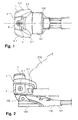
- FIG. 1 shows a plan view of a touring ski binding 100 with a front jaw 1 according to the invention in the holding position.
- the figure on the left is at the ski binding 100 front, while in the figure right at the touring ski binding 100 is back. Accordingly, in the figure on the left also at the front jaw 1 front, while in the figure right at the front jaw 1 is back.
- FIG. 1 From the touring ski binding 100 is in the FIG. 1 only one sole element 101 and the front jaw 1 mounted on the sole element 101 are shown.
- This sole element 101 is pivotable about an axis oriented in the direction of the ski relative to the ski (not shown). Since this axis is arranged below the front jaw 1, it is in the in FIG. 1 shown top view of the toe 1 covered.
- the inventive toe 1 comprises a holding element 2 for holding a ski boot in the region of the tip of the ski boot.
- This holding element 2 is manufactured in one piece and comprises laterally two regions 3.1, 3.2, which reach somewhat rearward, and which can embrace the tip of the ski boot laterally and upwards in order to hold the ski boot in the toe 1.
- the two somewhat reaching backward areas 3.1, 3.2 support the ski boot held in the front jaw 1 side. If the energy of a lateral impact on the ski, touring ski binding 100, or the ski boot exceeds a certain energy, the ski boot held in the toe 1 can be released from the toe 1 by a lateral safety release.
- the holding element 2 is pivotally mounted about a pivot axis 4 and can be pivoted with its two slightly reaching backward areas 3.1, 3.2 to the side.
- This pivot axis 4 extends coaxially to a arranged in the holding element 2 screw 5, the head is accessible from above and therefore in the supervision of FIG. 1 can be seen. If the sole member 101 of the touring ski binding 100 as in the FIG. 1 is horizontally aligned, the pivot axis 4 is vertically aligned. By contrast, when the sole element 101 is pivoted about the axis oriented in the transverse direction, the pivot axis 4 is pivoted in a vertical plane extending in the longitudinal direction of the ski.
- FIG. 2 also shows the ski touring binding 100 with the inventive toe 1.
- FIG. 1 show the FIG. 2 however, a side view of Touring ski binding 100.
- a ski boot 200 held in touring ski binding 100 is shown with a dashed line.
- the dotted line also extends through the rearwardly extending portion 3.1 of the support member 2, which is located in front of the ski boot 200 in the side view shown.
- the two stops 6.1 have a substantially square cross section, but the side edges of the cross section are slightly bent.
- the crosshead of a spindle 7 can be seen, which is aligned horizontally in the direction of the ski by the two stops 6.1 and thus extends through the holding element 2 of the front jaw 1.
- FIG. 3 shows a cross-section oriented in the direction of the ski through the front jaw 1 mounted on the sole element 101.
- This cross-section runs along the pivot axis 4 and is thus aligned perpendicular to the sole element 101. Since it is assumed below that the sole element 101 is aligned in parallel with the ski, orientation indications used such as "top”, “bottom”, “vertical”, “rear” or “front” coincide with the input reference system of the (fictitious) ski.
- the front jaw 1 has a base element 8 which is mounted on the sole element 101.
- the base element 8 is slightly embedded in the sole element 101.
- the axis 102 about which the sole element 101 can be pivoted, extends partly through the sole element 101 and partly through the base element 8, whereby the base element 8 is fastened to the sole element 101.
- the base element 8 comprises a pin 9 pointing vertically upwards.
- This pin 9 extends coaxially with the pivot axis 4 and thus also coaxially with the screw 5.
- the retaining element 2 is pivotably mounted on the pin 9 about the pivot axis 4.
- the pin 9 and the bearing of the pin 9 in the holding element 2 together form a radial bearing 13.
- the toe 1 can be adjusted by the height adjustment of the support member 2 to different ski boots with different thicknesses soles.
- the spindle 7 is aligned horizontally in the direction of the cross-machine direction by the two stops 6.1, 6.2 and thus by the holding element 2.
- the spindle 7 also extends through an opening 10 in the journal 9 oriented horizontally in the direction of the ski. Therefore, when the holding member 2 is adjusted by adjusting the screw 5 in its height relative to the base member 8 and the pin 9, the spindle 7 is moved in the opening 10 in the pin 9 in the vertical direction downwards or upwards.
- the spindle 7 has in the region of its two ends depending on a counter-rotating thread on which each one of the two stops 6.1, 6.2 is mounted. Since the two stops 6.1, 6.2 seen in Skiquerides have a substantially square cross section, they do not rotate when the spindle 7 is rotated in the support member 2 about its longitudinal axis. Therefore, the two stops 6.1, 6.2 can be moved by turning the spindle 7 toward and away from each other.
- the spindle may also have at its one end a fixed head, which forms a first stop, and in the region of its other end have a thread on which a second stop is mounted.
- the head of the spindle should be rotatable in the holding element, while the second stop should not be rotatable, when the spindle is rotated about its longitudinal axis.
- This also allows the two stops to be moved towards and away from each other by turning the spindle. Therefore, in both cases by turning the spindle 7, a distance between the stops 6.1, 6.2 can be adjusted, whereby the energy can be adjusted, which can be absorbed by the toe jaw 1 in a lateral shock until it comes to a lateral safety release.
- a stub element 12.1, 12.2 is arranged on each side of the pin 9. These two stub elements 12.1, 12.2 each have an opening through which the spindle 7 is guided.
- the two stub elements 12.1, 12.2 are mounted movably along the spindle 7. Further, in each case a spring 11.1, 11.2 is arranged on each stop 6.1, 6.2 between the respective stop 6.1, 6.2 and the stub element 12.1, 12.2 on the respective side of the pin 9. These springs 11.1, 11.2 are each supported with a first end opposite the respective stop 6.1, 6.2. In addition, they are each supported with a second end opposite the stub element 12.1, 12.2, which is located on its side of the pin 9.
- the spindle 7 Since the spindle 7 is movable relative to the holding element 2 in the transverse direction and since the two stops 6.1, 6.2 are also movable relative to the holding element 2 in the transverse direction, the spindle 7 moves with the two stops 6.1, 6.2 in such a way that the force generated by the two springs 11.1, 11.2 is exercised, uniformly distributed to the two springs 11.1, 11.2 and the two Stoss institute 12.1, 12.2.
- the two mating elements 12.1, 12.2 are coupled to one another via the spindle 7 serving as the coupling element, so that they press against the pin 9 with the same force.
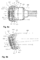
- FIGS. 4a and 4b each show a plan view of a horizontal cross section through the front jaw 1, which runs along the longitudinal axis of the spindle 7.
- FIG. 1 is in the FIGS. 4a and 4b 100 on the left at the touring binding 100, while in the figures on the right at the touring binding 100 is behind. Accordingly, in the figures left on the front jaw 1 front, while in the figures right at the front jaw 1 back.
- FIG. 4a is the toe 1 as already in the FIG. 1 shown as part of touring ski binding 100.
- the retaining element is also as in the FIG. 4a in the stop position.
- the outline of the ski boot 200 held in the toe 1 is shown by a dashed line.
- the ski boot 200 is also shown.
- the holding element 2 is in the FIG. 4b not in the holding position, but in a laterally pivoted away from the holding position position.
- the ski boot 200 is also shown moved away from the center of the ski. As a result, the operation of the front jaw 1 is illustrated with a lateral safety release.
- the spindle 7 is guided in Skiquerides through the opening 10 in the pin 9.
- the two mating elements 12.1, 12.2 are coupled to each other via the spindle 7, so that they press against the pin 9 with a substantially equal force.
- the two stub elements 12.1, 12.2, viewed in the longitudinal direction of the ski have a vertically aligned, flat surface in front of and behind the spindle 7.
- the pin 9 in turn has seen in the ski longitudinal direction on both sides before and behind the opening on a flat surface, which is aligned vertically in the ski longitudinal direction.
- the cross section of the pin 9 is not continuous circular, but has seen through the bilaterally arranged flat surfaces seen in the ski longitudinal direction on both sides each have a flat, flat area.
- a lateral safety release can occur if a lateral impact on the ski, touring ski binding 100 or ski boot 200 exceeds a certain energy.
- the ski boot 200 presses laterally against the lying in the direction of movement of the ski boot 200, slightly reaching back area 3.1, 3.2 of the holding element 2 and against the corresponding roller 14.1, 14.2.
- the holding element 2 is pivoted about the pivot axis 4. The farther the holding element 2 is pivoted, the further the flat surfaces of the stub elements 12.1, 12.2 and the pin 9 are tilted and the further the two stub elements 12.1, 12.2 are moved apart in comparison to the holding position.
- the ski boot 200 can roll on the roller 14.1, 14.2 located in the direction of movement of the ski boot 200 and detach laterally from the toe 1.
- the energy that can be absorbed by the toe piece 1 until the ski boot 200 is released from the toe piece 1 can be adjusted.
- the two stops 6.1, 6.2 moved by turning the spindle 7 toward or away from each other, whereby the two springs 11.1, 11.2 are biased more or less strongly.
- FIG. 5 shows a vertical in the ski center in the ski longitudinal direction extending cross section through the ski binding 100 with the inventive toe 1. Again left in the figure in the touring ski binding 100 front, while right in the figure at the touring ski binding 100 is back. Accordingly, turn left in the figure at the toe 1 front, while right in the figure at the toe 1 back.
- the cross-sectional view runs through the base element 8 and shows how the pin 9 is mounted in the holding element 2.
- the cross section runs along the pivot axis 4 and the screw 5 and cuts the spindle 7 and the axis 102 about which the sole element 101 of the touring ski binding can be pivoted, at a right angle.
- the Figures 6a and 6b each show a schematic representation of a plan view of another inventive toe 51.
- the front jaw 51 comprises a holding element 52 which is pivotable about a pivot axis 54 is pivotally mounted on a base member 58.
- This base element 58 may for example be mounted on a ski. But it can also be mounted on a sole element of a touring ski binding, for example, which is pivotable about an axis oriented horizontally in the ski direction.
- the base member 58 includes a vertically upwardly facing pin 59.
- This pin 59 has on its seen in the longitudinal direction of the front side a flat, flat portion whose surface is vertically aligned in the cross-machine direction. Otherwise, the cross section of the pin 59 is circular.
- the pin 59 together with a counterpart of the holding member 52, a radial bearing 63. Due to this radial bearing 63, the holding member 52 relative to the base member 58 is pivotally mounted about the pivot axis 54. In this case, the holding element 52 is not movable in the radial direction to the pivot axis 54 relative to the base element 58 due to the radial bearing 63 and can only be pivoted about the pivot axis 54.
- a coupling element 57 is slidably mounted in the ski longitudinal direction.
- This coupling element 57 has the shape of a rectangular plate, which is aligned with its main surfaces in parallel. In its center, the coupling element 57 has an opening through which the pin 59 is guided.
- a front edge 56 of the opening in the coupling member 57 is flattened and lies flat on the flat, flat portion of the pin 59 when the holding member 52 is in a holding position.
- a piston 62 In front of the rear edge of the opening in the coupling element 57 is a piston 62, which is pressed by a spring 61 away from the rear edge of the opening to the pin 59. As a result, the pin 59 is clamped between the front edge 56 of the opening and the piston 62.
- the front edge 56 of the opening and the piston 62 each form a stub element. Since the coupling member 57 is movable radially of the radial bearing 63, it can distribute the force caused by the spring 61 on the front edge 56 of the opening in the coupling member 57 and the piston 62, so that the front edge 56 and the piston 62 with a substantially same Force against the radial bearing 63 are pressed.
- the coupling element 57 also pivoted. As a result, both the flattened front edge 56 of the opening in the coupling element 57 and the piston 62 are pivoted together. Since the flattened front edge 56 is thereby tilted relative to the flat, flattened portion of the pin 59, the coupling member 57 is pushed in the radial direction relative to the pin 59 and thus with respect to the pivot axis 54 and against the holding member 52 to the front. Thus, the rear edge of the opening in the coupling member 57 is pushed forward in the direction of pin 59, whereby the spring 61 is compressed.
- the front jaw 51 can absorb a certain amount of energy during a lateral pivoting movement of the holding element 52 about the pivot axis 54 until a lateral safety release occurs.
- the absorbable energy can be adjusted by the bias of the spring 61. Due to the interplay of the flat, flattened portion of the pin 59 and the flattened front edge 56, the flat, flattened portion of the pin 59 forms a positioning structure, while the flattened front edge 56 forms a counter-structure to the positioning structure.
- first inventive toe 1 can also when in the Figures 6a and 6b shown toe 51 a height of the holding member 52 are adjusted relative to the base member 58.
- a mechanism is also provided with a screw, as it is explained in detail for the first inventive toe 1. This mechanism, however, is in the Figures 6a and 6b can not be seen.
- the coupling element can be formed in the second embodiment, for example, as a spindle. It may be aligned in the longitudinal direction of the ski or in the direction of the ski. In addition, it may be movably mounted in the ski longitudinal direction or in the ski direction. The same is true for the spindle according to the first embodiment, which can be formed as the coupling element according to the second embodiment.
- the front jaw as described may include two stucco elements or even more than two stamper elements. Moreover, in both embodiments, only one or two of the stub elements can be movably mounted along the coupling element.
- the coupling element is mounted on the holding element.
- the coupling element can also be mounted on the base element.
- such a modification may, for example, be such that the coupling element is movably arranged in the longitudinal direction of the ski on the base element, while the pin is arranged on the retaining element.
- the pin is pivotally mounted about the pivot axis in a counterpart arranged on the base element. Therefore, in this embodiment, when the holding member is pivoted about the pivot axis, the flat flattened portion on the front side of the pin is also pivoted with respect to the base member.
- this area is tilted relative to the flat, front edge of the opening in the coupling element, whereby the coupling element is pushed forward relative to the base element.
- the spring is also tensioned, whereby an energy absorption is made possible by the toe.
- the two stops, springs, stamper and the spindle can be arranged on the base element. If the pin is not arranged on the base element, but on the holding element and is pivotally mounted in a counterpart on the base element about the pivot axis, so the push elements can press against the pin.
- both the two stops, the springs, the Stossetti, the spindle and the pin are mounted on the base element, so the two Stossrion can press against the counterpart on the holding element, in which the pin is rotatably mounted.
- the counterpart on the holding element should have a shape such that the distance is increased by at least one of the two Stoss institute to the pivot axis when the holding element is pivoted away from the holding position.
- the stub elements and the element of the radial bearing, with which cooperate the Stossiata can be shaped differently. It is not necessary that one or both of the male members and the corresponding member of the radial bearing have planar surfaces as in the above-described embodiments, which are mutually tilted when the retainer is moved away from the holding position.
- the one or both stub elements and the corresponding element of the radial bearing can for example also have a bulge and indentation. What is important about their shape is that at least one of the mating elements is moved away from the axis of rotation when the holding element is pivoted away from the holding position. By this movement of the or the push elements one or more springs or elastic elements can be compressed or pulled apart. As a result, energy can be absorbed by the toe piece during a pivoting movement of the retaining element.
- a mechanism which allows a safety release in the reverse direction.
- such a mechanism may for example be given by the fact that the holding element is rotatably mounted not only about the pivot axis on the base element, but also slightly about a horizontal, substantially aligned in the cross direction axis. This can be achieved, for example, by virtue of the fact that the counterpart, with which the holding element is mounted on the pin, allows the holding element to rock about a horizontal axis which is oriented substantially in the direction of the ski.
- the mating elements should be designed such that they hold the holding element in the holding position in a predetermined orientation about the horizontal, aligned substantially in the direction of the cross axis.
- the support member When an upward force acts on the ski boot or a downward force acts on the toe or ski, the support member can be pivoted about the horizontal, substantially cross-machine directional axis until the ski boot is released from the toe. During this pivoting movement The two jaw elements should be pressed apart so that the front jaw can absorb energy until it comes to a safety release in the reverse direction.
- the two laterally arranged Stoss comprise not only in the ski longitudinal direction aligned, have vertical, flat surfaces, but also surround the pin at the front and rear something to support the pin front and rear.
- the two die elements are pressed apart when the holding element with the two die elements is pivoted about the horizontal, oriented substantially in the direction of the cross grain axis with respect to the pin.
- no adjustment of the two Stossieri is required, since they are forced apart due to their vertical extent, when the holding element is pivoted about a horizontal, aligned substantially in the direction of the cross axis relative to the pin.
- a front jaw is provided which allows both an optimally controlled lateral safety release and permits a compact design.
Landscapes
- Footwear And Its Accessory, Manufacturing Method And Apparatuses (AREA)
Applications Claiming Priority (1)
| Application Number | Priority Date | Filing Date | Title |
|---|---|---|---|
| CH01560/13A CH708560A1 (de) | 2013-09-11 | 2013-09-11 | Vorderbacken für eine Skibindung. |
Publications (2)
| Publication Number | Publication Date |
|---|---|
| EP2851108A1 true EP2851108A1 (fr) | 2015-03-25 |
| EP2851108B1 EP2851108B1 (fr) | 2016-12-21 |
Family
ID=49377984
Family Applications (1)
| Application Number | Title | Priority Date | Filing Date |
|---|---|---|---|
| EP14405068.9A Active EP2851108B1 (fr) | 2013-09-11 | 2014-09-08 | Mâchoire avant pour une fixation de ski |
Country Status (2)
| Country | Link |
|---|---|
| EP (1) | EP2851108B1 (fr) |
| CH (1) | CH708560A1 (fr) |
Cited By (1)
| Publication number | Priority date | Publication date | Assignee | Title |
|---|---|---|---|---|
| EP3851174A1 (fr) | 2020-01-16 | 2021-07-21 | Fritschi AG - Swiss Bindings | Butée avant pour une fixation de ski |
Citations (12)
| Publication number | Priority date | Publication date | Assignee | Title |
|---|---|---|---|---|
| DE1960489A1 (de) * | 1969-12-02 | 1971-06-09 | Iser Iser Herbert | Sicherheitsbacken fuer Schibindungen |
| DE2144440A1 (fr) * | 1970-09-14 | 1972-04-06 | ||
| FR2201107A1 (fr) * | 1972-09-27 | 1974-04-26 | Salomon Georges P J | |
| JPS5120468U (fr) * | 1974-07-31 | 1976-02-14 | ||
| DE2907917A1 (de) * | 1978-03-03 | 1979-09-06 | Look Sa | Sicherheitsbindung fuer ski |
| FR2424037A1 (fr) * | 1978-04-28 | 1979-11-23 | Salomon & Fils F | |
| DE2949866A1 (de) | 1978-12-28 | 1980-07-17 | Salomon & Fils F | Sicherheitsbindung |
| US4494769A (en) | 1981-06-30 | 1985-01-22 | Ste Look | Ski-binding toe abutment member for a ski boot having a truncated sole |
| FR2585262A2 (fr) * | 1985-07-24 | 1987-01-30 | Look Sa | Fixation de securite pour ski |
| EP0352492A2 (fr) * | 1988-07-28 | 1990-01-31 | Geze Sport International Gmbh | Mâchoire avant à déclenchement lateral pour des fixations de ski de sécurité |
| FR2652272A2 (fr) * | 1986-04-08 | 1991-03-29 | Look Sa | Fixation de securite pour ski. |
| EP2181736A1 (fr) * | 2008-10-31 | 2010-05-05 | Rottefella AS | talonnière avec deux axes d'ouverture |
-
2013
- 2013-09-11 CH CH01560/13A patent/CH708560A1/de not_active Application Discontinuation
-
2014
- 2014-09-08 EP EP14405068.9A patent/EP2851108B1/fr active Active
Patent Citations (12)
| Publication number | Priority date | Publication date | Assignee | Title |
|---|---|---|---|---|
| DE1960489A1 (de) * | 1969-12-02 | 1971-06-09 | Iser Iser Herbert | Sicherheitsbacken fuer Schibindungen |
| DE2144440A1 (fr) * | 1970-09-14 | 1972-04-06 | ||
| FR2201107A1 (fr) * | 1972-09-27 | 1974-04-26 | Salomon Georges P J | |
| JPS5120468U (fr) * | 1974-07-31 | 1976-02-14 | ||
| DE2907917A1 (de) * | 1978-03-03 | 1979-09-06 | Look Sa | Sicherheitsbindung fuer ski |
| FR2424037A1 (fr) * | 1978-04-28 | 1979-11-23 | Salomon & Fils F | |
| DE2949866A1 (de) | 1978-12-28 | 1980-07-17 | Salomon & Fils F | Sicherheitsbindung |
| US4494769A (en) | 1981-06-30 | 1985-01-22 | Ste Look | Ski-binding toe abutment member for a ski boot having a truncated sole |
| FR2585262A2 (fr) * | 1985-07-24 | 1987-01-30 | Look Sa | Fixation de securite pour ski |
| FR2652272A2 (fr) * | 1986-04-08 | 1991-03-29 | Look Sa | Fixation de securite pour ski. |
| EP0352492A2 (fr) * | 1988-07-28 | 1990-01-31 | Geze Sport International Gmbh | Mâchoire avant à déclenchement lateral pour des fixations de ski de sécurité |
| EP2181736A1 (fr) * | 2008-10-31 | 2010-05-05 | Rottefella AS | talonnière avec deux axes d'ouverture |
Cited By (1)
| Publication number | Priority date | Publication date | Assignee | Title |
|---|---|---|---|---|
| EP3851174A1 (fr) | 2020-01-16 | 2021-07-21 | Fritschi AG - Swiss Bindings | Butée avant pour une fixation de ski |
Also Published As
| Publication number | Publication date |
|---|---|
| CH708560A1 (de) | 2015-03-13 |
| EP2851108B1 (fr) | 2016-12-21 |
Similar Documents
| Publication | Publication Date | Title |
|---|---|---|
| EP3766550B1 (fr) | Dispositif automatique avant | |
| EP3702005B1 (fr) | Talonnière | |
| DE1960002C3 (de) | Auslösende Skibindung mit einer verschwenkbaren Trittplatte | |
| DE2655896A1 (de) | Sicherheitsbindung | |
| EP3053632B1 (fr) | Talonnière | |
| DE3141425C1 (de) | Sicherheitsbindung für Ski | |
| EP3120903B1 (fr) | Talonnière | |
| EP3345659B1 (fr) | Talonnière automatique pour une fixation de ski | |
| DE2927059A1 (de) | Skischuh mit integrierter skibindung | |
| EP2174695B1 (fr) | Butée d'une fixation de ski dont le boitier est articulé autour d'un axe transversal | |
| DE2221105B2 (de) | Sicherheits-Skibindung | |
| EP3167943B1 (fr) | Talonniere comprenant une structure d'appui de talon | |
| DE2802251A1 (de) | Sicherheitsskibindung mit einem seitlich ausschwenkbaren sohlenhalter | |
| DE3109734A1 (de) | "sicherheitsbindung fuer ski" | |
| EP2851108B1 (fr) | Mâchoire avant pour une fixation de ski | |
| DE3151222C2 (de) | Vorderbacken für eine Sicherheits-Skibindung | |
| DE1478141B2 (de) | Vorderbacken für Sicherheits-Skibindungen | |
| EP2965791B1 (fr) | Unité de positionnement automatique d'avant de chaussure de skis pour fixation à ergots | |
| DE2429610C3 (de) | Sicherheitsskibindung | |
| DE102013209277A1 (de) | Zehenhalter mit Einsteighilfe | |
| DE1956653A1 (de) | Vorderbacken fuer Sicherheits-Skibindungen | |
| DE202010010115U1 (de) | Mechanik für einen Bürostuhl | |
| EP3095492B1 (fr) | Mâchoire avant d'une fixation de sûreté | |
| CH705586A2 (de) | Frontautomat. | |
| DE1478141C3 (de) | Vorderbacken für Sicherheits-Skibindungen |
Legal Events
| Date | Code | Title | Description |
|---|---|---|---|
| PUAI | Public reference made under article 153(3) epc to a published international application that has entered the european phase |
Free format text: ORIGINAL CODE: 0009012 |
|
| 17P | Request for examination filed |
Effective date: 20140908 |
|
| AK | Designated contracting states |
Kind code of ref document: A1 Designated state(s): AL AT BE BG CH CY CZ DE DK EE ES FI FR GB GR HR HU IE IS IT LI LT LU LV MC MK MT NL NO PL PT RO RS SE SI SK SM TR |
|
| AX | Request for extension of the european patent |
Extension state: BA ME |
|
| RBV | Designated contracting states (corrected) |
Designated state(s): AL AT BE BG CH CY CZ DE DK EE ES FI FR GB GR HR HU IE IS IT LI LT LU LV MC MK MT NL NO PL PT RO RS SE SI SK SM TR |
|
| R17P | Request for examination filed (corrected) |
Effective date: 20150507 |
|
| GRAP | Despatch of communication of intention to grant a patent |
Free format text: ORIGINAL CODE: EPIDOSNIGR1 |
|
| INTG | Intention to grant announced |
Effective date: 20160324 |
|
| GRAJ | Information related to disapproval of communication of intention to grant by the applicant or resumption of examination proceedings by the epo deleted |
Free format text: ORIGINAL CODE: EPIDOSDIGR1 |
|
| INTC | Intention to grant announced (deleted) | ||
| GRAP | Despatch of communication of intention to grant a patent |
Free format text: ORIGINAL CODE: EPIDOSNIGR1 |
|
| INTG | Intention to grant announced |
Effective date: 20160811 |
|
| GRAS | Grant fee paid |
Free format text: ORIGINAL CODE: EPIDOSNIGR3 |
|
| GRAA | (expected) grant |
Free format text: ORIGINAL CODE: 0009210 |
|
| AK | Designated contracting states |
Kind code of ref document: B1 Designated state(s): AL AT BE BG CH CY CZ DE DK EE ES FI FR GB GR HR HU IE IS IT LI LT LU LV MC MK MT NL NO PL PT RO RS SE SI SK SM TR |
|
| REG | Reference to a national code |
Ref country code: GB Ref legal event code: FG4D Free format text: NOT ENGLISH |
|
| REG | Reference to a national code |
Ref country code: CH Ref legal event code: EP Ref country code: CH Ref legal event code: NV Representative=s name: KELLER AND PARTNER PATENTANWAELTE AG, CH |
|
| REG | Reference to a national code |
Ref country code: IE Ref legal event code: FG4D Free format text: LANGUAGE OF EP DOCUMENT: GERMAN |
|
| REG | Reference to a national code |
Ref country code: AT Ref legal event code: REF Ref document number: 854975 Country of ref document: AT Kind code of ref document: T Effective date: 20170115 |
|
| REG | Reference to a national code |
Ref country code: DE Ref legal event code: R096 Ref document number: 502014002255 Country of ref document: DE |
|
| PG25 | Lapsed in a contracting state [announced via postgrant information from national office to epo] |
Ref country code: LV Free format text: LAPSE BECAUSE OF FAILURE TO SUBMIT A TRANSLATION OF THE DESCRIPTION OR TO PAY THE FEE WITHIN THE PRESCRIBED TIME-LIMIT Effective date: 20161221 |
|
| REG | Reference to a national code |
Ref country code: LT Ref legal event code: MG4D |
|
| REG | Reference to a national code |
Ref country code: NL Ref legal event code: MP Effective date: 20161221 |
|
| PG25 | Lapsed in a contracting state [announced via postgrant information from national office to epo] |
Ref country code: SE Free format text: LAPSE BECAUSE OF FAILURE TO SUBMIT A TRANSLATION OF THE DESCRIPTION OR TO PAY THE FEE WITHIN THE PRESCRIBED TIME-LIMIT Effective date: 20161221 Ref country code: GR Free format text: LAPSE BECAUSE OF FAILURE TO SUBMIT A TRANSLATION OF THE DESCRIPTION OR TO PAY THE FEE WITHIN THE PRESCRIBED TIME-LIMIT Effective date: 20170322 Ref country code: NO Free format text: LAPSE BECAUSE OF FAILURE TO SUBMIT A TRANSLATION OF THE DESCRIPTION OR TO PAY THE FEE WITHIN THE PRESCRIBED TIME-LIMIT Effective date: 20170321 Ref country code: LT Free format text: LAPSE BECAUSE OF FAILURE TO SUBMIT A TRANSLATION OF THE DESCRIPTION OR TO PAY THE FEE WITHIN THE PRESCRIBED TIME-LIMIT Effective date: 20161221 |
|
| PG25 | Lapsed in a contracting state [announced via postgrant information from national office to epo] |
Ref country code: HR Free format text: LAPSE BECAUSE OF FAILURE TO SUBMIT A TRANSLATION OF THE DESCRIPTION OR TO PAY THE FEE WITHIN THE PRESCRIBED TIME-LIMIT Effective date: 20161221 Ref country code: FI Free format text: LAPSE BECAUSE OF FAILURE TO SUBMIT A TRANSLATION OF THE DESCRIPTION OR TO PAY THE FEE WITHIN THE PRESCRIBED TIME-LIMIT Effective date: 20161221 Ref country code: RS Free format text: LAPSE BECAUSE OF FAILURE TO SUBMIT A TRANSLATION OF THE DESCRIPTION OR TO PAY THE FEE WITHIN THE PRESCRIBED TIME-LIMIT Effective date: 20161221 |
|
| PG25 | Lapsed in a contracting state [announced via postgrant information from national office to epo] |
Ref country code: NL Free format text: LAPSE BECAUSE OF FAILURE TO SUBMIT A TRANSLATION OF THE DESCRIPTION OR TO PAY THE FEE WITHIN THE PRESCRIBED TIME-LIMIT Effective date: 20161221 |
|
| PG25 | Lapsed in a contracting state [announced via postgrant information from national office to epo] |
Ref country code: CZ Free format text: LAPSE BECAUSE OF FAILURE TO SUBMIT A TRANSLATION OF THE DESCRIPTION OR TO PAY THE FEE WITHIN THE PRESCRIBED TIME-LIMIT Effective date: 20161221 Ref country code: EE Free format text: LAPSE BECAUSE OF FAILURE TO SUBMIT A TRANSLATION OF THE DESCRIPTION OR TO PAY THE FEE WITHIN THE PRESCRIBED TIME-LIMIT Effective date: 20161221 Ref country code: IS Free format text: LAPSE BECAUSE OF FAILURE TO SUBMIT A TRANSLATION OF THE DESCRIPTION OR TO PAY THE FEE WITHIN THE PRESCRIBED TIME-LIMIT Effective date: 20170421 Ref country code: RO Free format text: LAPSE BECAUSE OF FAILURE TO SUBMIT A TRANSLATION OF THE DESCRIPTION OR TO PAY THE FEE WITHIN THE PRESCRIBED TIME-LIMIT Effective date: 20161221 Ref country code: SK Free format text: LAPSE BECAUSE OF FAILURE TO SUBMIT A TRANSLATION OF THE DESCRIPTION OR TO PAY THE FEE WITHIN THE PRESCRIBED TIME-LIMIT Effective date: 20161221 |
|
| PG25 | Lapsed in a contracting state [announced via postgrant information from national office to epo] |
Ref country code: SM Free format text: LAPSE BECAUSE OF FAILURE TO SUBMIT A TRANSLATION OF THE DESCRIPTION OR TO PAY THE FEE WITHIN THE PRESCRIBED TIME-LIMIT Effective date: 20161221 Ref country code: ES Free format text: LAPSE BECAUSE OF FAILURE TO SUBMIT A TRANSLATION OF THE DESCRIPTION OR TO PAY THE FEE WITHIN THE PRESCRIBED TIME-LIMIT Effective date: 20161221 Ref country code: PT Free format text: LAPSE BECAUSE OF FAILURE TO SUBMIT A TRANSLATION OF THE DESCRIPTION OR TO PAY THE FEE WITHIN THE PRESCRIBED TIME-LIMIT Effective date: 20170421 Ref country code: PL Free format text: LAPSE BECAUSE OF FAILURE TO SUBMIT A TRANSLATION OF THE DESCRIPTION OR TO PAY THE FEE WITHIN THE PRESCRIBED TIME-LIMIT Effective date: 20161221 Ref country code: IT Free format text: LAPSE BECAUSE OF FAILURE TO SUBMIT A TRANSLATION OF THE DESCRIPTION OR TO PAY THE FEE WITHIN THE PRESCRIBED TIME-LIMIT Effective date: 20161221 Ref country code: BG Free format text: LAPSE BECAUSE OF FAILURE TO SUBMIT A TRANSLATION OF THE DESCRIPTION OR TO PAY THE FEE WITHIN THE PRESCRIBED TIME-LIMIT Effective date: 20170321 |
|
| REG | Reference to a national code |
Ref country code: DE Ref legal event code: R097 Ref document number: 502014002255 Country of ref document: DE |
|
| PLBE | No opposition filed within time limit |
Free format text: ORIGINAL CODE: 0009261 |
|
| STAA | Information on the status of an ep patent application or granted ep patent |
Free format text: STATUS: NO OPPOSITION FILED WITHIN TIME LIMIT |
|
| 26N | No opposition filed |
Effective date: 20170922 |
|
| PG25 | Lapsed in a contracting state [announced via postgrant information from national office to epo] |
Ref country code: DK Free format text: LAPSE BECAUSE OF FAILURE TO SUBMIT A TRANSLATION OF THE DESCRIPTION OR TO PAY THE FEE WITHIN THE PRESCRIBED TIME-LIMIT Effective date: 20161221 |
|
| PG25 | Lapsed in a contracting state [announced via postgrant information from national office to epo] |
Ref country code: SI Free format text: LAPSE BECAUSE OF FAILURE TO SUBMIT A TRANSLATION OF THE DESCRIPTION OR TO PAY THE FEE WITHIN THE PRESCRIBED TIME-LIMIT Effective date: 20161221 |
|
| PG25 | Lapsed in a contracting state [announced via postgrant information from national office to epo] |
Ref country code: MC Free format text: LAPSE BECAUSE OF FAILURE TO SUBMIT A TRANSLATION OF THE DESCRIPTION OR TO PAY THE FEE WITHIN THE PRESCRIBED TIME-LIMIT Effective date: 20161221 |
|
| REG | Reference to a national code |
Ref country code: IE Ref legal event code: MM4A |
|
| REG | Reference to a national code |
Ref country code: BE Ref legal event code: MM Effective date: 20170930 |
|
| PG25 | Lapsed in a contracting state [announced via postgrant information from national office to epo] |
Ref country code: LU Free format text: LAPSE BECAUSE OF NON-PAYMENT OF DUE FEES Effective date: 20170908 |
|
| REG | Reference to a national code |
Ref country code: FR Ref legal event code: ST Effective date: 20180531 |
|
| PG25 | Lapsed in a contracting state [announced via postgrant information from national office to epo] |
Ref country code: IE Free format text: LAPSE BECAUSE OF NON-PAYMENT OF DUE FEES Effective date: 20170908 |
|
| PG25 | Lapsed in a contracting state [announced via postgrant information from national office to epo] |
Ref country code: FR Free format text: LAPSE BECAUSE OF NON-PAYMENT OF DUE FEES Effective date: 20171002 Ref country code: BE Free format text: LAPSE BECAUSE OF NON-PAYMENT OF DUE FEES Effective date: 20170930 |
|
| PG25 | Lapsed in a contracting state [announced via postgrant information from national office to epo] |
Ref country code: MT Free format text: LAPSE BECAUSE OF FAILURE TO SUBMIT A TRANSLATION OF THE DESCRIPTION OR TO PAY THE FEE WITHIN THE PRESCRIBED TIME-LIMIT Effective date: 20161221 |
|
| GBPC | Gb: european patent ceased through non-payment of renewal fee |
Effective date: 20180908 |
|
| PG25 | Lapsed in a contracting state [announced via postgrant information from national office to epo] |
Ref country code: HU Free format text: LAPSE BECAUSE OF FAILURE TO SUBMIT A TRANSLATION OF THE DESCRIPTION OR TO PAY THE FEE WITHIN THE PRESCRIBED TIME-LIMIT; INVALID AB INITIO Effective date: 20140908 |
|
| PG25 | Lapsed in a contracting state [announced via postgrant information from national office to epo] |
Ref country code: CY Free format text: LAPSE BECAUSE OF FAILURE TO SUBMIT A TRANSLATION OF THE DESCRIPTION OR TO PAY THE FEE WITHIN THE PRESCRIBED TIME-LIMIT Effective date: 20161221 Ref country code: GB Free format text: LAPSE BECAUSE OF NON-PAYMENT OF DUE FEES Effective date: 20180908 |
|
| PG25 | Lapsed in a contracting state [announced via postgrant information from national office to epo] |
Ref country code: MK Free format text: LAPSE BECAUSE OF FAILURE TO SUBMIT A TRANSLATION OF THE DESCRIPTION OR TO PAY THE FEE WITHIN THE PRESCRIBED TIME-LIMIT Effective date: 20161221 |
|
| PG25 | Lapsed in a contracting state [announced via postgrant information from national office to epo] |
Ref country code: TR Free format text: LAPSE BECAUSE OF FAILURE TO SUBMIT A TRANSLATION OF THE DESCRIPTION OR TO PAY THE FEE WITHIN THE PRESCRIBED TIME-LIMIT Effective date: 20161221 |
|
| PG25 | Lapsed in a contracting state [announced via postgrant information from national office to epo] |
Ref country code: AL Free format text: LAPSE BECAUSE OF FAILURE TO SUBMIT A TRANSLATION OF THE DESCRIPTION OR TO PAY THE FEE WITHIN THE PRESCRIBED TIME-LIMIT Effective date: 20161221 |
|
| REG | Reference to a national code |
Ref country code: CH Ref legal event code: PFA Owner name: FRITSCHI AG - SWISS BINDINGS, CH Free format text: FORMER OWNER: FRITSCHI AG - SWISS BINDINGS, CH |
|
| PGFP | Annual fee paid to national office [announced via postgrant information from national office to epo] |
Ref country code: AT Payment date: 20220909 Year of fee payment: 9 |
|
| PGFP | Annual fee paid to national office [announced via postgrant information from national office to epo] |
Ref country code: DE Payment date: 20221121 Year of fee payment: 9 |
|
| REG | Reference to a national code |
Ref country code: DE Ref legal event code: R119 Ref document number: 502014002255 Country of ref document: DE |
|
| REG | Reference to a national code |
Ref country code: AT Ref legal event code: MM01 Ref document number: 854975 Country of ref document: AT Kind code of ref document: T Effective date: 20230908 |
|
| PG25 | Lapsed in a contracting state [announced via postgrant information from national office to epo] |
Ref country code: AT Free format text: LAPSE BECAUSE OF NON-PAYMENT OF DUE FEES Effective date: 20230908 |
|
| PG25 | Lapsed in a contracting state [announced via postgrant information from national office to epo] |
Ref country code: DE Free format text: LAPSE BECAUSE OF NON-PAYMENT OF DUE FEES Effective date: 20240403 Ref country code: AT Free format text: LAPSE BECAUSE OF NON-PAYMENT OF DUE FEES Effective date: 20230908 |
|
| REG | Reference to a national code |
Ref country code: CH Ref legal event code: U11 Free format text: ST27 STATUS EVENT CODE: U-0-0-U10-U11 (AS PROVIDED BY THE NATIONAL OFFICE) Effective date: 20251001 |
|
| PGFP | Annual fee paid to national office [announced via postgrant information from national office to epo] |
Ref country code: CH Payment date: 20251001 Year of fee payment: 12 |