EP2851213A1 - Système de gonflage de pneu et procédé de commande - Google Patents
Système de gonflage de pneu et procédé de commande Download PDFInfo
- Publication number
- EP2851213A1 EP2851213A1 EP14184854.9A EP14184854A EP2851213A1 EP 2851213 A1 EP2851213 A1 EP 2851213A1 EP 14184854 A EP14184854 A EP 14184854A EP 2851213 A1 EP2851213 A1 EP 2851213A1
- Authority
- EP
- European Patent Office
- Prior art keywords
- pressurized gas
- pressure
- pulse
- tire
- duration time
- Prior art date
- Legal status (The legal status is an assumption and is not a legal conclusion. Google has not performed a legal analysis and makes no representation as to the accuracy of the status listed.)
- Granted
Links
Images

Classifications
-
- B—PERFORMING OPERATIONS; TRANSPORTING
- B60—VEHICLES IN GENERAL
- B60C—VEHICLE TYRES; TYRE INFLATION; TYRE CHANGING; CONNECTING VALVES TO INFLATABLE ELASTIC BODIES IN GENERAL; DEVICES OR ARRANGEMENTS RELATED TO TYRES
- B60C23/00—Devices for measuring, signalling, controlling, or distributing tyre pressure or temperature, specially adapted for mounting on vehicles; Arrangement of tyre inflating devices on vehicles, e.g. of pumps or of tanks; Tyre cooling arrangements
- B60C23/02—Signalling devices actuated by tyre pressure
- B60C23/04—Signalling devices actuated by tyre pressure mounted on the wheel or tyre
- B60C23/0408—Signalling devices actuated by tyre pressure mounted on the wheel or tyre transmitting the signals by non-mechanical means from the wheel or tyre to a vehicle body mounted receiver
-
- B—PERFORMING OPERATIONS; TRANSPORTING
- B60—VEHICLES IN GENERAL
- B60C—VEHICLE TYRES; TYRE INFLATION; TYRE CHANGING; CONNECTING VALVES TO INFLATABLE ELASTIC BODIES IN GENERAL; DEVICES OR ARRANGEMENTS RELATED TO TYRES
- B60C23/00—Devices for measuring, signalling, controlling, or distributing tyre pressure or temperature, specially adapted for mounting on vehicles; Arrangement of tyre inflating devices on vehicles, e.g. of pumps or of tanks; Tyre cooling arrangements
- B60C23/001—Devices for manually or automatically controlling or distributing tyre pressure whilst the vehicle is moving
- B60C23/003—Devices for manually or automatically controlling or distributing tyre pressure whilst the vehicle is moving comprising rotational joints between vehicle-mounted pressure sources and the tyres
- B60C23/00309—Devices for manually or automatically controlling or distributing tyre pressure whilst the vehicle is moving comprising rotational joints between vehicle-mounted pressure sources and the tyres characterised by the location of the components, e.g. valves, sealings, conduits or sensors
- B60C23/00318—Devices for manually or automatically controlling or distributing tyre pressure whilst the vehicle is moving comprising rotational joints between vehicle-mounted pressure sources and the tyres characterised by the location of the components, e.g. valves, sealings, conduits or sensors on the wheels or the hubs
-
- B—PERFORMING OPERATIONS; TRANSPORTING
- B60—VEHICLES IN GENERAL
- B60C—VEHICLE TYRES; TYRE INFLATION; TYRE CHANGING; CONNECTING VALVES TO INFLATABLE ELASTIC BODIES IN GENERAL; DEVICES OR ARRANGEMENTS RELATED TO TYRES
- B60C23/00—Devices for measuring, signalling, controlling, or distributing tyre pressure or temperature, specially adapted for mounting on vehicles; Arrangement of tyre inflating devices on vehicles, e.g. of pumps or of tanks; Tyre cooling arrangements
- B60C23/001—Devices for manually or automatically controlling or distributing tyre pressure whilst the vehicle is moving
- B60C23/003—Devices for manually or automatically controlling or distributing tyre pressure whilst the vehicle is moving comprising rotational joints between vehicle-mounted pressure sources and the tyres
- B60C23/00354—Details of valves
-
- B—PERFORMING OPERATIONS; TRANSPORTING
- B60—VEHICLES IN GENERAL
- B60C—VEHICLE TYRES; TYRE INFLATION; TYRE CHANGING; CONNECTING VALVES TO INFLATABLE ELASTIC BODIES IN GENERAL; DEVICES OR ARRANGEMENTS RELATED TO TYRES
- B60C23/00—Devices for measuring, signalling, controlling, or distributing tyre pressure or temperature, specially adapted for mounting on vehicles; Arrangement of tyre inflating devices on vehicles, e.g. of pumps or of tanks; Tyre cooling arrangements
- B60C23/001—Devices for manually or automatically controlling or distributing tyre pressure whilst the vehicle is moving
- B60C23/003—Devices for manually or automatically controlling or distributing tyre pressure whilst the vehicle is moving comprising rotational joints between vehicle-mounted pressure sources and the tyres
- B60C23/00372—Devices for manually or automatically controlling or distributing tyre pressure whilst the vehicle is moving comprising rotational joints between vehicle-mounted pressure sources and the tyres characterised by fluid diagrams
Definitions
- This patent application relates to a tire inflation system and a method of control.
- a method of controlling inflation of a tire may include determining tire pressure by providing a pulse of pressurized gas to a tire valve and measuring a pressure of the pulse of pressurized gas.
- the pulse of pressurized gas may not open the tire valve when the tire pressure is greater than or equal to the target tire pressure.
- a method of controlling inflation of a tire may include determining a first pressurized gas pulse duration time.
- a first pulse of pressurized gas may be provided to a tire for the first pressurized gas pulse duration time. Pressure of the pressurized gas associated with the first pulse may be measured.
- a second pressurized gas pulse duration time may be determined.
- the second pulse of pressurized gas may be provided to the tire for the second pressurized gas pulse duration time. Pressure of the pressurized gas associated with the second pulse may be measured.
- the pressure associated with the first pulse may be compared with the pressure associated with the second pulse.
- the tire may be underinflated when the pressure associated with the first pressurized gas pulse is within a predetermined amount of the pressure associated with the second pressurized gas pulse.
- a tire inflation system may include a pressurized gas source, an outlet valve, an inlet valve, a first pressure sensor, and a second pressure sensor.
- the pressurized gas source may be configured to provide a pressurized gas.
- the outlet valve may control flow of pressurized gas to a tire.
- the inlet valve may control flow of pressurized gas to the outlet valve.
- the first pressure sensor may detect pressure of the pressurized gas provided by the pressurized gas source.
- the second pressure sensor may be disposed between the inlet valve and the outlet valve.
- the vehicle 10 may be of any suitable type, such as a motor vehicle like a truck, bus, farm equipment, military transport or weaponry vehicle, or cargo loading equipment for land, air, or marine vessels.
- a motor vehicle like a truck, bus, farm equipment, military transport or weaponry vehicle, or cargo loading equipment for land, air, or marine vessels.
- the vehicle 10 may include a plurality of wheel assemblies 20.
- Each wheel assembly 20 may include at least one inflatable tire 22 that may be mounted on an associated wheel 24.
- Each tire 22 may have a tire valve 26 that may facilitate inflation of the tire 22.
- a tire valve 26 may extend through a hole in an associated wheel 24 and may be configured to provide gas to a chamber that may be at least partially defined by the tire 22 and the wheel 24.
- Each tire valve 26 may be normally closed to inhibit pressurized gas from exiting the tire 22 through the tire valve 26.
- the tire valve 26 may open when pressurized gas is supplied to the tire valve 26 under sufficient pressure, such as a pressure that is greater than the pressure inside the tire 22.
- the tire valve locations are generalized for illustration purposes and are not intended to be limiting.
- the vehicle 10 may also include a tire inflation system 30 that may monitor or determine tire pressure and that may inflate one or more tires 22. More specifically, the tire inflation system 30 may be configured to provide a pressurized gas or pressurized gas mixture to one or more tires 22 via a corresponding tire valve 26.
- pressurized gas may refer to a pressurized gas or a pressurized gas mixture in this application.
- the tire inflation system 30 may include a pressurized gas source 32, a gas supply subsystem 34, and a control system 36.
- the pressurized gas source 32 may be configured to supply and/or store a volume of a pressurized gas or pressurized gas mixture, such as air and/or nitrogen.
- the pressurized gas source 32 may include a tank and/or a pump like a compressor that may be driven by a vehicle engine or vehicle power source.
- the pressurized gas source 32 may be disposed on the vehicle 10 and may be configured to provide a pressurized gas or pressurized gas mixture at a pressure that is greater than or equal to a target tire inflation pressure or a target inflation pressure of a tire 22.
- Each tire 22 may or may not have the same target tire pressure in one or more embodiments.
- the gas supply subsystem 34 may fluidly connect the pressurized gas source 32 to one or more tires 22.
- the gas supply subsystem 34 may include one or more conduits 40, such as a hose, tubing, pipe, or combinations thereof, which may provide pressurized gas to at least one tire 22 via a corresponding tire valve 26.
- the conduit configuration in Figure 1 is merely exemplary. For instance, a single conduit 40 may be associated with each tire 22 rather than multiple tires as is shown in the bottom half of Figure 1 .
- the gas supply subsystem 34 may include an inlet valve 42, at least one outlet valve 44, a first pressure sensor 46, and a second pressure sensor 48.
- the inlet valve 42 may enable or disable the flow of pressurized gas from an outlet of the pressurized gas source 32 to at least one outlet valve 44. Operation of the inlet valve 42 may be controlled by the control system 36.
- the inlet valve 42 may include or may be controlled by an actuator, such as solenoid, that may actuate the inlet valve 42 between an open position and a closed position.
- pressurized gas may flow from the pressurized gas source 32 to a manifold 50.
- the manifold 50 may distribute pressurized gas to multiple conduits 40 and may be disposed between the inlet valve 42 and one or more outlet valves 44.
- pressurized gas In the closed position, pressurized gas may be inhibited from flowing from the pressurized gas source 32 to the manifold 50.
- the inlet valve 42 may be normally closed under predetermined operating conditions, such as when the vehicle 10 is not operational or turned off or when the vehicle engine is not running. As such, the inlet valve 42 may inhibit depressurization of the pressurized gas source 32 in the event of a downstream leak.
- the outlet valve 44 may enable or disable the flow of pressurized gas from the manifold 50 to a tire 22 or tire valve 26.
- FIG 1 six outlet valves 44 are shown, although it is contemplated that a greater or lesser number of outlet valves 44 may be provided.
- Each outlet valve 44 may be associated with a different tire 22 and a different conduit 40.
- each outlet valve 44 may be actuated independently of the inlet valve 42 and independently of each other. As such, the inflation and pressure assessment of different tires 22 or sets of tires 22 may be independently controlled. Operation of the outlet valve 44 may be controlled by the control system 36.
- the outlet valve 44 may include or may be controlled by an actuator, such as solenoid, that may actuate the outlet valve 44 between an open position and a closed position.
- pressurized gas may flow from the manifold 50 to at least one corresponding tire valve 26.
- pressurized gas may be inhibited from flowing from the manifold 50 to at least one corresponding tire valve 26.
- pressurized gas may not be constantly provided to one or more tires 22, which may facilitate the use of pressure pulses to determine tire pressure as will be discussed in more detail below.
- the outlet valve 44 may allow a conduit 40 to be vented to the surrounding environment between the outlet valve 44 and a corresponding tire valve 26.
- the outlet valve 44 may be normally closed under predetermined operating conditions, such as when the vehicle 10 is not operational or turned off or when the vehicle engine is not running.
- the first pressure sensor 46 may be configured to detect the pressure of the pressurized gas provided by the pressurized gas source 32.
- the first pressure sensor 46 may be of any suitable type and may be fluidly connected to the pressurized gas source 32.
- the first pressure sensor 46 may be fluidly connected to the pressurized gas source 32 between the pressurized gas source 32 and the inlet valve 42.
- the second pressure sensor 48 may be configured to detect the pressure of the pressurized gas provided to a tire 22 or tire valve 26.
- the second pressure sensor 48 may be of any suitable type and may be disposed between the inlet valve 42 and the tire valve 26 and may be fluidly connected to the manifold 50. As such, the second pressure sensor 48 may be isolated from the pressurized gas source 32 by closing the inlet valve 42. In at least one embodiment, the second pressure sensor 48 may be disposed between the inlet valve 42 and one or more outlet valves 44 so that the second pressure sensor 48 may be used to detect the pressure of pressurized gas supplied to different tires. Alternatively, multiple second pressure sensors 48 may be provided that may detect the pressure supplied to a particular conduit 40 or particular tire 22.
- the control system 36 may monitor and control operation of the tire inflation system 30.
- the control system 36 may include one or more electronic controllers or control modules that may monitor and/or control various components of the tire inflation system 30.
- the control system 36 may be configured to control actuation of the inlet valve 42 and the outlet valve 44 to control the flow of pressurized gas.
- the control system 36 may be configured to receive data from the first pressure sensor 46 and the second pressure sensor 48 that may be indicative of pressure.
- communication between the control system 36 and these components is represented by the double arrowed line that is located adjacent to the control system 36.
- control logic which may be implemented or affected in hardware, software, or a combination of hardware and software.
- the various functions may be affected by a programmed microprocessor.
- the control logic may be implemented using any of a number of known programming and processing techniques or strategies and is not limited to the order or sequence illustrated. For instance, interrupt or event-driven processing may be employed in real-time control applications rather than a purely sequential strategy as illustrated. Likewise, parallel processing, multitasking, or multi-threaded systems and methods may be used.
- Control logic may be independent of the particular programming language, operating system, processor, or circuitry used to develop and/or implement the control logic illustrated. Likewise, depending upon the particular programming language and processing strategy, various functions may be performed in the sequence illustrated, at substantially the same time, or in a different sequence while accomplishing the method of control. The illustrated functions may be modified, or in some cases omitted, without departing from the scope intended.
- the method may be executed by the control system 36 and may be implemented as a closed loop control system. Moreover, the method may be enabled or disabled based on the operating state of the vehicle 10. For example, the method or control logic may be enabled when the vehicle ignition is turned on, the engine is running, or when the vehicle is in motion in one or more embodiments. In addition, the method may be manually activated.
- the method will be primarily described in the context of evaluating the pressure of a single tire, but it is to be understood that the method may be applied to evaluate and/or adjust the pressure of multiple tires or sets of tires.
- the method may determine tire pressure and inflate a tire or alert a driver as appropriate depending on the tire pressure.
- Tire pressure may be determined by routing multiple pulses of pressurized gas to a tire or tire valve rather than directly measuring tire pressure with a pressure sensor disposed inside the tire. Pulses may increase in magnitude. As such, the duration of a pulse or force exerted by a pulse may be greater than the duration or force exerted by a previous pulse.
- the pulses may be provided at less than a desired or target tire pressure and thus may not open an associated tire valve when the tire pressure is greater than or equal to the target tire pressure. As such, the tire valve may not open in response to a pulse and the pressure in the tire may not equalize with pressure in the conduit that supplies the pulse to the tire.
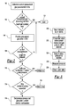
- a current pressurized gas pulse duration time may be determined.
- the current pressurized gas pulse duration time may be the length of time or duration of a pressurized gas pulse in which pressurized gas is provided from the pressurized gas source 32 to the tire valve 26.
- the current pressurized gas pulse duration time may be configured to not open the tire valve 26 when the associated tire 22 is inflated at or above the target tire pressure.
- the target tire pressure may be a predetermined value that may be indicative of a desired tire pressure and may account for design tolerances of the tire valve 26 or the tolerance range associated with opening the tire valve 26.
- the current pressurized gas pulse duration time may be calculated or determined in various ways. For example, the current pressurized gas pulse duration time may be based on a previous pressurized gas pulse duration time and the pressure of the pressurized gas provided by the pressurized gas source.
- the previous pressurized gas pulse duration time may be generated and stored in memory during a previous iteration. Initially or during an initial iteration, the previous pressurized gas pulse duration time may be a default value or default period of time. Such a default value or default period of time may be configured to provide a pulse that is less than the target tire pressure to reduce the likelihood of opening the tire valve 26 during the first iteration even if the tire is underinflated. After the initial iteration, a previous pressurized gas pulse duration time may be retrieved from memory and based on the preceding iteration.
- the pressure of the pressurized gas supplied by the pressurized gas source 32 may be detected by or based on data from the first pressure sensor 46.
- the pressure of gas from the pressurized gas source 32 may not be constant.
- the supply pressure may increase due to operation of the pump or compressor and may decrease in response to system demand, such as operation of pneumatic components like pneumatic actuators or pneumatic brakes.
- Lower supply pressure from the pressurized gas source 32 may reduce the flow rate, thereby increasing the amount of time that the inlet valve 42 may be opened to provide a pressure pulse having a desired magnitude or that exerts a desired force on the tire valve 26.
- the pressure data from the first pressure sensor 46 may be used to calculate or obtain an adjustment value that may account for supply pressure variations.
- the supply pressure provided by the first pressure sensor 46 may be used to calculate an adjustment value or reference an adjustment value in a lookup table that may be populated with a set of adjustment values that may be obtained by development testing.
- Each adjustment value in a lookup table may be associated with a corresponding supply pressure value.
- the adjustment value may be a positive value, negative value, or zero.
- the current pressurized gas pulse duration time may be obtained by adding the adjustment value to the previous pressurized gas pulse duration time.
- the current pressurized gas pulse duration time may be compared to a maximum pressurized gas pulse duration time.
- the maximum pressurized gas pulse duration time may be based on or correlated with the target tire pressure. More specifically, the maximum pressurized gas pulse duration time may be a pulse length that may open the tire valve when the tire is inflated to the target tire pressure. If the current pressurized gas pulse duration time is greater than the maximum pressurized gas pulse duration time, then the tire may be inflated to at least the target tire pressure (i.e., the tire is not underinflated) and the method may end at block 104 (presuming proper operation of the pressurized gas source 32 and the gas supply subsystem 34). If the current pressurized gas pulse duration time is not greater than the maximum pressurized gas pulse duration time, then the method may continue at block 106.
- a pulse of pressurized gas may be provided to the tire and the pulse pressure may be measured.
- a pressurized gas pulse may be provided by opening and closing the inlet valve 42 and the outlet valve 44 as will be discussed in more detail below with reference to Figure 3 .
- the pressure of the current pressure pulse or current pulse pressure is compared to the target tire pressure.
- the current pulse pressure may be measured or determined based on data from the second pressure sensor 48 when the inlet valve 42 is closed. If the current pulse pressure is not less than the target tire pressure, then the tire is inflated to at least the target tire pressure (i.e., the tire is not underinflated) and the method may end at block 104. If the current pulse pressure is less than the target tire pressure, then the method may continue at block 110.
- the second pressure sensor 48 may detect substantially similar pressure readings after each pulse and after the tire pressure equalizes with the supply line pressure. If a rapid tire pressure leak is in progress, then the second pressure sensor 48 may detect substantially different pressure readings for each pulse due to the leak. As such, the difference between the current pulse pressure and the previous pulse pressure may not be within the threshold range. Likewise, the current measured pulse pressure and the previous measured pulse pressure may not be within the threshold range when the tire valve 26 is not opened by successive pressure pulses. For instance, the pulse pressure during the current iteration may be higher than the pulse pressure during the previous iteration since the pressure pulse duration (and thus the effective pressure) may be increased each iteration.
- a third pulse of pressurized gas may be provided to the tire.
- the third pulse of pressurized gas may be provided for a third pressurized gas pulse duration time that may be longer than the second pressurized gas pulse duration time. Additional pressure pulses may be provided until the method terminates at block 104, 112, or 116.
Landscapes
- Engineering & Computer Science (AREA)
- Mechanical Engineering (AREA)
- Measuring Fluid Pressure (AREA)
- Vehicle Cleaning, Maintenance, Repair, Refitting, And Outriggers (AREA)
Applications Claiming Priority (5)
| Application Number | Priority Date | Filing Date | Title |
|---|---|---|---|
| US14/029,884 US10391824B2 (en) | 2013-09-18 | 2013-09-18 | Tire inflation system and method of control |
| US14/049,846 US20150096655A1 (en) | 2013-10-09 | 2013-10-09 | Tire Inflation System Having a Pressure Equalization Valve Assembly |
| US14/051,798 US9409450B2 (en) | 2013-10-11 | 2013-10-11 | Tire inflation system and method of control |
| US14/051,847 US9597931B2 (en) | 2013-10-11 | 2013-10-11 | Tire inflation system and method of control |
| US14/080,941 US9346329B2 (en) | 2013-11-15 | 2013-11-15 | Tire inflation system and method of control |
Publications (2)
| Publication Number | Publication Date |
|---|---|
| EP2851213A1 true EP2851213A1 (fr) | 2015-03-25 |
| EP2851213B1 EP2851213B1 (fr) | 2018-02-28 |
Family
ID=51564485
Family Applications (5)
| Application Number | Title | Priority Date | Filing Date |
|---|---|---|---|
| EP14184853.1A Withdrawn EP2851218A1 (fr) | 2013-09-18 | 2014-09-15 | Système de gonflage de pneu ayant un ensemble de soupape d'égalisation de pression |
| EP14184855.6A Withdrawn EP2851214A1 (fr) | 2013-09-18 | 2014-09-15 | Système de gonflage de pneu et procédé de commande |
| EP14184852.3A Active EP2851212B1 (fr) | 2013-09-18 | 2014-09-15 | Système de gonflage de pneu et procédé de commande |
| EP14184854.9A Active EP2851213B1 (fr) | 2013-09-18 | 2014-09-15 | Système de gonflage de pneu et procédé de commande |
| EP14184857.2A Active EP2851216B1 (fr) | 2013-09-18 | 2014-09-15 | Système de gonflage de pneu et procédé de commande |
Family Applications Before (3)
| Application Number | Title | Priority Date | Filing Date |
|---|---|---|---|
| EP14184853.1A Withdrawn EP2851218A1 (fr) | 2013-09-18 | 2014-09-15 | Système de gonflage de pneu ayant un ensemble de soupape d'égalisation de pression |
| EP14184855.6A Withdrawn EP2851214A1 (fr) | 2013-09-18 | 2014-09-15 | Système de gonflage de pneu et procédé de commande |
| EP14184852.3A Active EP2851212B1 (fr) | 2013-09-18 | 2014-09-15 | Système de gonflage de pneu et procédé de commande |
Family Applications After (1)
| Application Number | Title | Priority Date | Filing Date |
|---|---|---|---|
| EP14184857.2A Active EP2851216B1 (fr) | 2013-09-18 | 2014-09-15 | Système de gonflage de pneu et procédé de commande |
Country Status (1)
| Country | Link |
|---|---|
| EP (5) | EP2851218A1 (fr) |
Cited By (1)
| Publication number | Priority date | Publication date | Assignee | Title |
|---|---|---|---|---|
| CN115723487A (zh) * | 2021-08-30 | 2023-03-03 | 比亚迪股份有限公司 | 胎压控制方法及装置、车辆和存储介质 |
Families Citing this family (6)
| Publication number | Priority date | Publication date | Assignee | Title |
|---|---|---|---|---|
| US10023017B1 (en) | 2017-01-18 | 2018-07-17 | Pygmalion Technologies LLC | Air-drag powered devices for vehicle wheels |
| US10183535B1 (en) | 2017-07-21 | 2019-01-22 | Pygmalion Technologies LLC | Air motion powered devices for vehicle wheels |
| CN110015136A (zh) * | 2017-10-18 | 2019-07-16 | 宁波轩悦行电动汽车服务有限公司 | 用于监控电动汽车状态的智能控制系统 |
| US10821788B2 (en) * | 2018-01-22 | 2020-11-03 | Ford Global Technologies, Llc | Activation of tire pressure measurement systems |
| US11298987B2 (en) * | 2019-04-09 | 2022-04-12 | Dana Heavy Vehicle Systems Group, Llc | Method of determining the health of a seal in a tire inflation system |
| DE102023111259A1 (de) * | 2023-05-02 | 2024-11-07 | Zf Cv Systems Global Gmbh | Verfahren zum Erkennen von defektverursachten Temperaturänderungen an Wheelends eines Fahrzeugs, Auswerteeinheit und Fahrzeug |
Citations (4)
| Publication number | Priority date | Publication date | Assignee | Title |
|---|---|---|---|---|
| US5180456A (en) * | 1991-11-15 | 1993-01-19 | Eaton Corporation | Adaptive inflation control for vehicle central tire inflation system |
| US20040055291A1 (en) * | 2001-04-09 | 2004-03-25 | Michelin Recherche Et Technique S.A. | Inflation circuit, in particular for a tire mounted on a wheel, and corresponding wheel |
| US20040173296A1 (en) * | 2003-03-06 | 2004-09-09 | White Jay D. | Tire inflation system apparatus and method |
| USRE41756E1 (en) | 2001-12-04 | 2010-09-28 | Dana Heavy Vehicle Systems Group, Llc | Tire pressure monitoring method |
Family Cites Families (13)
| Publication number | Priority date | Publication date | Assignee | Title |
|---|---|---|---|---|
| US2156841A (en) * | 1938-04-09 | 1939-05-02 | Walter H Davis | Tire pressure controlling apparatus |
| DE2826635A1 (de) * | 1978-06-19 | 1980-01-03 | Daimler Benz Ag | Einrichtung zur regelung des luftdruckes von fahrzeugreifen |
| DE3703128A1 (de) * | 1987-02-03 | 1988-08-11 | Continental Gummi Werke Ag | Ueberwachungsverfahren und -vorrichtung fuer dynamisch beanspruchte gummiartikel |
| US4860579A (en) * | 1988-05-25 | 1989-08-29 | Eaton Corporation | Tire leakage detection method for central tire inflation system |
| US5231872A (en) * | 1991-02-21 | 1993-08-03 | Ttc/Truck Tech Corp. | Tire monitoring apparatus and method |
| US6457502B1 (en) | 2000-12-15 | 2002-10-01 | Caterpillar Inc | Dual tire pressure balance system |
| US6499552B2 (en) * | 2001-06-01 | 2002-12-31 | Meritor Heavy Vehicle Technology, L.L.C. | Drive axle control system |
| US20030216845A1 (en) * | 2002-05-15 | 2003-11-20 | Williston Scott Lawton | Automatic tire inflation based on vehicle loading conditions |
| US8844596B2 (en) * | 2008-09-29 | 2014-09-30 | Global Engineering Marketing Llc | Central tire inflation wheel assembly, valve and central tire inflation system |
| MX2012014030A (es) * | 2010-07-30 | 2013-02-12 | Hendrickson Usa Llc | Sistema para inflar neumaticos de equilibrio neumatico de presion constante. |
| WO2012068583A1 (fr) * | 2010-11-19 | 2012-05-24 | Equalaire Systems, Inc. | Système de gestion de pneu |
| US8564429B2 (en) * | 2011-02-27 | 2013-10-22 | Joe Huayue Zhou | Dual tire pressure monitor with equalizer apparatus and tire inflation system integration |
| DE102012023509A1 (de) * | 2012-11-30 | 2014-06-05 | Wabco Gmbh | Verfahren zur Regelung oder Einstellung eines Reifenfülldrucks an Fahrzeugreifen und Reifenfülldruck-Einstellvorrichtung |
-
2014
- 2014-09-15 EP EP14184853.1A patent/EP2851218A1/fr not_active Withdrawn
- 2014-09-15 EP EP14184855.6A patent/EP2851214A1/fr not_active Withdrawn
- 2014-09-15 EP EP14184852.3A patent/EP2851212B1/fr active Active
- 2014-09-15 EP EP14184854.9A patent/EP2851213B1/fr active Active
- 2014-09-15 EP EP14184857.2A patent/EP2851216B1/fr active Active
Patent Citations (4)
| Publication number | Priority date | Publication date | Assignee | Title |
|---|---|---|---|---|
| US5180456A (en) * | 1991-11-15 | 1993-01-19 | Eaton Corporation | Adaptive inflation control for vehicle central tire inflation system |
| US20040055291A1 (en) * | 2001-04-09 | 2004-03-25 | Michelin Recherche Et Technique S.A. | Inflation circuit, in particular for a tire mounted on a wheel, and corresponding wheel |
| USRE41756E1 (en) | 2001-12-04 | 2010-09-28 | Dana Heavy Vehicle Systems Group, Llc | Tire pressure monitoring method |
| US20040173296A1 (en) * | 2003-03-06 | 2004-09-09 | White Jay D. | Tire inflation system apparatus and method |
Cited By (1)
| Publication number | Priority date | Publication date | Assignee | Title |
|---|---|---|---|---|
| CN115723487A (zh) * | 2021-08-30 | 2023-03-03 | 比亚迪股份有限公司 | 胎压控制方法及装置、车辆和存储介质 |
Also Published As
| Publication number | Publication date |
|---|---|
| EP2851216B1 (fr) | 2021-02-17 |
| EP2851218A1 (fr) | 2015-03-25 |
| EP2851212A1 (fr) | 2015-03-25 |
| EP2851216A1 (fr) | 2015-03-25 |
| EP2851212B1 (fr) | 2016-07-20 |
| EP2851214A1 (fr) | 2015-03-25 |
| EP2851213B1 (fr) | 2018-02-28 |
Similar Documents
| Publication | Publication Date | Title |
|---|---|---|
| US10391824B2 (en) | Tire inflation system and method of control | |
| EP2851213B1 (fr) | Système de gonflage de pneu et procédé de commande | |
| US9815340B2 (en) | Tire inflation system and method of control | |
| US9346329B2 (en) | Tire inflation system and method of control | |
| US9597931B2 (en) | Tire inflation system and method of control | |
| US9278587B2 (en) | Tire inflation system and method of control | |
| US9409450B2 (en) | Tire inflation system and method of control | |
| US9221395B2 (en) | System and method of monitoring wheel end seal assembly wear | |
| CN105793073B (zh) | 确定轮胎压力的方法 | |
| US20150096655A1 (en) | Tire Inflation System Having a Pressure Equalization Valve Assembly | |
| US10099518B2 (en) | Central tire inflation system and method | |
| EP3325289B1 (fr) | Système centralisé de gonflage de pneu | |
| US10625542B2 (en) | Tire pressure management system and method of decreasing tire pressure | |
| US11155126B2 (en) | Central tyre inflation system and method | |
| GB2538971A (en) | Central tyre inflation system and method | |
| CN107667018A (zh) | 降低胎压的方法 | |
| US10807419B2 (en) | Pressure supply diagnostics and controls and the tire inflation system made therewith | |
| WO2017160936A1 (fr) | Ensemble valve pour un système de gonflage de pneumatique | |
| GB2538972A (en) | Central tyre inflation system and method |
Legal Events
| Date | Code | Title | Description |
|---|---|---|---|
| PUAI | Public reference made under article 153(3) epc to a published international application that has entered the european phase |
Free format text: ORIGINAL CODE: 0009012 |
|
| 17P | Request for examination filed |
Effective date: 20140915 |
|
| AK | Designated contracting states |
Kind code of ref document: A1 Designated state(s): AL AT BE BG CH CY CZ DE DK EE ES FI FR GB GR HR HU IE IS IT LI LT LU LV MC MK MT NL NO PL PT RO RS SE SI SK SM TR |
|
| AX | Request for extension of the european patent |
Extension state: BA ME |
|
| R17P | Request for examination filed (corrected) |
Effective date: 20150925 |
|
| RBV | Designated contracting states (corrected) |
Designated state(s): AL AT BE BG CH CY CZ DE DK EE ES FI FR GB GR HR HU IE IS IT LI LT LU LV MC MK MT NL NO PL PT RO RS SE SI SK SM TR |
|
| RIC1 | Information provided on ipc code assigned before grant |
Ipc: B60C 23/00 20060101AFI20170718BHEP Ipc: B60C 23/04 20060101ALI20170718BHEP |
|
| GRAP | Despatch of communication of intention to grant a patent |
Free format text: ORIGINAL CODE: EPIDOSNIGR1 |
|
| STAA | Information on the status of an ep patent application or granted ep patent |
Free format text: STATUS: GRANT OF PATENT IS INTENDED |
|
| INTG | Intention to grant announced |
Effective date: 20170926 |
|
| GRAS | Grant fee paid |
Free format text: ORIGINAL CODE: EPIDOSNIGR3 |
|
| GRAA | (expected) grant |
Free format text: ORIGINAL CODE: 0009210 |
|
| STAA | Information on the status of an ep patent application or granted ep patent |
Free format text: STATUS: THE PATENT HAS BEEN GRANTED |
|
| AK | Designated contracting states |
Kind code of ref document: B1 Designated state(s): AL AT BE BG CH CY CZ DE DK EE ES FI FR GB GR HR HU IE IS IT LI LT LU LV MC MK MT NL NO PL PT RO RS SE SI SK SM TR |
|
| REG | Reference to a national code |
Ref country code: GB Ref legal event code: FG4D Ref country code: CH Ref legal event code: EP |
|
| REG | Reference to a national code |
Ref country code: AT Ref legal event code: REF Ref document number: 973699 Country of ref document: AT Kind code of ref document: T Effective date: 20180315 |
|
| REG | Reference to a national code |
Ref country code: IE Ref legal event code: FG4D |
|
| REG | Reference to a national code |
Ref country code: DE Ref legal event code: R096 Ref document number: 602014021540 Country of ref document: DE |
|
| REG | Reference to a national code |
Ref country code: NL Ref legal event code: FP |
|
| REG | Reference to a national code |
Ref country code: SE Ref legal event code: TRGR |
|
| REG | Reference to a national code |
Ref country code: LT Ref legal event code: MG4D |
|
| REG | Reference to a national code |
Ref country code: AT Ref legal event code: MK05 Ref document number: 973699 Country of ref document: AT Kind code of ref document: T Effective date: 20180228 |
|
| PG25 | Lapsed in a contracting state [announced via postgrant information from national office to epo] |
Ref country code: FI Free format text: LAPSE BECAUSE OF FAILURE TO SUBMIT A TRANSLATION OF THE DESCRIPTION OR TO PAY THE FEE WITHIN THE PRESCRIBED TIME-LIMIT Effective date: 20180228 Ref country code: CY Free format text: LAPSE BECAUSE OF FAILURE TO SUBMIT A TRANSLATION OF THE DESCRIPTION OR TO PAY THE FEE WITHIN THE PRESCRIBED TIME-LIMIT Effective date: 20180228 Ref country code: ES Free format text: LAPSE BECAUSE OF FAILURE TO SUBMIT A TRANSLATION OF THE DESCRIPTION OR TO PAY THE FEE WITHIN THE PRESCRIBED TIME-LIMIT Effective date: 20180228 Ref country code: LT Free format text: LAPSE BECAUSE OF FAILURE TO SUBMIT A TRANSLATION OF THE DESCRIPTION OR TO PAY THE FEE WITHIN THE PRESCRIBED TIME-LIMIT Effective date: 20180228 Ref country code: NO Free format text: LAPSE BECAUSE OF FAILURE TO SUBMIT A TRANSLATION OF THE DESCRIPTION OR TO PAY THE FEE WITHIN THE PRESCRIBED TIME-LIMIT Effective date: 20180528 Ref country code: HR Free format text: LAPSE BECAUSE OF FAILURE TO SUBMIT A TRANSLATION OF THE DESCRIPTION OR TO PAY THE FEE WITHIN THE PRESCRIBED TIME-LIMIT Effective date: 20180228 |
|
| PG25 | Lapsed in a contracting state [announced via postgrant information from national office to epo] |
Ref country code: GR Free format text: LAPSE BECAUSE OF FAILURE TO SUBMIT A TRANSLATION OF THE DESCRIPTION OR TO PAY THE FEE WITHIN THE PRESCRIBED TIME-LIMIT Effective date: 20180529 Ref country code: BG Free format text: LAPSE BECAUSE OF FAILURE TO SUBMIT A TRANSLATION OF THE DESCRIPTION OR TO PAY THE FEE WITHIN THE PRESCRIBED TIME-LIMIT Effective date: 20180528 Ref country code: RS Free format text: LAPSE BECAUSE OF FAILURE TO SUBMIT A TRANSLATION OF THE DESCRIPTION OR TO PAY THE FEE WITHIN THE PRESCRIBED TIME-LIMIT Effective date: 20180228 Ref country code: AT Free format text: LAPSE BECAUSE OF FAILURE TO SUBMIT A TRANSLATION OF THE DESCRIPTION OR TO PAY THE FEE WITHIN THE PRESCRIBED TIME-LIMIT Effective date: 20180228 Ref country code: LV Free format text: LAPSE BECAUSE OF FAILURE TO SUBMIT A TRANSLATION OF THE DESCRIPTION OR TO PAY THE FEE WITHIN THE PRESCRIBED TIME-LIMIT Effective date: 20180228 |
|
| REG | Reference to a national code |
Ref country code: FR Ref legal event code: PLFP Year of fee payment: 5 |
|
| PG25 | Lapsed in a contracting state [announced via postgrant information from national office to epo] |
Ref country code: PL Free format text: LAPSE BECAUSE OF FAILURE TO SUBMIT A TRANSLATION OF THE DESCRIPTION OR TO PAY THE FEE WITHIN THE PRESCRIBED TIME-LIMIT Effective date: 20180228 Ref country code: EE Free format text: LAPSE BECAUSE OF FAILURE TO SUBMIT A TRANSLATION OF THE DESCRIPTION OR TO PAY THE FEE WITHIN THE PRESCRIBED TIME-LIMIT Effective date: 20180228 Ref country code: RO Free format text: LAPSE BECAUSE OF FAILURE TO SUBMIT A TRANSLATION OF THE DESCRIPTION OR TO PAY THE FEE WITHIN THE PRESCRIBED TIME-LIMIT Effective date: 20180228 Ref country code: IT Free format text: LAPSE BECAUSE OF FAILURE TO SUBMIT A TRANSLATION OF THE DESCRIPTION OR TO PAY THE FEE WITHIN THE PRESCRIBED TIME-LIMIT Effective date: 20180228 Ref country code: AL Free format text: LAPSE BECAUSE OF FAILURE TO SUBMIT A TRANSLATION OF THE DESCRIPTION OR TO PAY THE FEE WITHIN THE PRESCRIBED TIME-LIMIT Effective date: 20180228 |
|
| REG | Reference to a national code |
Ref country code: DE Ref legal event code: R097 Ref document number: 602014021540 Country of ref document: DE |
|
| PG25 | Lapsed in a contracting state [announced via postgrant information from national office to epo] |
Ref country code: SK Free format text: LAPSE BECAUSE OF FAILURE TO SUBMIT A TRANSLATION OF THE DESCRIPTION OR TO PAY THE FEE WITHIN THE PRESCRIBED TIME-LIMIT Effective date: 20180228 Ref country code: DK Free format text: LAPSE BECAUSE OF FAILURE TO SUBMIT A TRANSLATION OF THE DESCRIPTION OR TO PAY THE FEE WITHIN THE PRESCRIBED TIME-LIMIT Effective date: 20180228 Ref country code: SM Free format text: LAPSE BECAUSE OF FAILURE TO SUBMIT A TRANSLATION OF THE DESCRIPTION OR TO PAY THE FEE WITHIN THE PRESCRIBED TIME-LIMIT Effective date: 20180228 Ref country code: CZ Free format text: LAPSE BECAUSE OF FAILURE TO SUBMIT A TRANSLATION OF THE DESCRIPTION OR TO PAY THE FEE WITHIN THE PRESCRIBED TIME-LIMIT Effective date: 20180228 |
|
| PLBE | No opposition filed within time limit |
Free format text: ORIGINAL CODE: 0009261 |
|
| STAA | Information on the status of an ep patent application or granted ep patent |
Free format text: STATUS: NO OPPOSITION FILED WITHIN TIME LIMIT |
|
| 26N | No opposition filed |
Effective date: 20181129 |
|
| PG25 | Lapsed in a contracting state [announced via postgrant information from national office to epo] |
Ref country code: SI Free format text: LAPSE BECAUSE OF FAILURE TO SUBMIT A TRANSLATION OF THE DESCRIPTION OR TO PAY THE FEE WITHIN THE PRESCRIBED TIME-LIMIT Effective date: 20180228 |
|
| PG25 | Lapsed in a contracting state [announced via postgrant information from national office to epo] |
Ref country code: MC Free format text: LAPSE BECAUSE OF FAILURE TO SUBMIT A TRANSLATION OF THE DESCRIPTION OR TO PAY THE FEE WITHIN THE PRESCRIBED TIME-LIMIT Effective date: 20180228 |
|
| REG | Reference to a national code |
Ref country code: CH Ref legal event code: PL |
|
| REG | Reference to a national code |
Ref country code: BE Ref legal event code: MM Effective date: 20180930 |
|
| REG | Reference to a national code |
Ref country code: IE Ref legal event code: MM4A |
|
| PG25 | Lapsed in a contracting state [announced via postgrant information from national office to epo] |
Ref country code: LU Free format text: LAPSE BECAUSE OF NON-PAYMENT OF DUE FEES Effective date: 20180915 |
|
| PG25 | Lapsed in a contracting state [announced via postgrant information from national office to epo] |
Ref country code: IE Free format text: LAPSE BECAUSE OF NON-PAYMENT OF DUE FEES Effective date: 20180915 |
|
| PG25 | Lapsed in a contracting state [announced via postgrant information from national office to epo] |
Ref country code: CH Free format text: LAPSE BECAUSE OF NON-PAYMENT OF DUE FEES Effective date: 20180930 Ref country code: BE Free format text: LAPSE BECAUSE OF NON-PAYMENT OF DUE FEES Effective date: 20180930 Ref country code: LI Free format text: LAPSE BECAUSE OF NON-PAYMENT OF DUE FEES Effective date: 20180930 |
|
| PG25 | Lapsed in a contracting state [announced via postgrant information from national office to epo] |
Ref country code: MT Free format text: LAPSE BECAUSE OF NON-PAYMENT OF DUE FEES Effective date: 20180915 |
|
| PG25 | Lapsed in a contracting state [announced via postgrant information from national office to epo] |
Ref country code: TR Free format text: LAPSE BECAUSE OF FAILURE TO SUBMIT A TRANSLATION OF THE DESCRIPTION OR TO PAY THE FEE WITHIN THE PRESCRIBED TIME-LIMIT Effective date: 20180228 |
|
| PG25 | Lapsed in a contracting state [announced via postgrant information from national office to epo] |
Ref country code: HU Free format text: LAPSE BECAUSE OF FAILURE TO SUBMIT A TRANSLATION OF THE DESCRIPTION OR TO PAY THE FEE WITHIN THE PRESCRIBED TIME-LIMIT; INVALID AB INITIO Effective date: 20140915 Ref country code: PT Free format text: LAPSE BECAUSE OF FAILURE TO SUBMIT A TRANSLATION OF THE DESCRIPTION OR TO PAY THE FEE WITHIN THE PRESCRIBED TIME-LIMIT Effective date: 20180228 |
|
| PG25 | Lapsed in a contracting state [announced via postgrant information from national office to epo] |
Ref country code: MK Free format text: LAPSE BECAUSE OF NON-PAYMENT OF DUE FEES Effective date: 20180228 |
|
| PG25 | Lapsed in a contracting state [announced via postgrant information from national office to epo] |
Ref country code: IS Free format text: LAPSE BECAUSE OF FAILURE TO SUBMIT A TRANSLATION OF THE DESCRIPTION OR TO PAY THE FEE WITHIN THE PRESCRIBED TIME-LIMIT Effective date: 20180628 |
|
| P01 | Opt-out of the competence of the unified patent court (upc) registered |
Effective date: 20230531 |
|
| PGFP | Annual fee paid to national office [announced via postgrant information from national office to epo] |
Ref country code: DE Payment date: 20250929 Year of fee payment: 12 |
|
| PGFP | Annual fee paid to national office [announced via postgrant information from national office to epo] |
Ref country code: NL Payment date: 20250926 Year of fee payment: 12 |
|
| PGFP | Annual fee paid to national office [announced via postgrant information from national office to epo] |
Ref country code: GB Payment date: 20250929 Year of fee payment: 12 |
|
| PGFP | Annual fee paid to national office [announced via postgrant information from national office to epo] |
Ref country code: FR Payment date: 20250925 Year of fee payment: 12 |
|
| PGFP | Annual fee paid to national office [announced via postgrant information from national office to epo] |
Ref country code: SE Payment date: 20250927 Year of fee payment: 12 |