EP2851235A2 - Agencement destiné à relier des éléments de rails conducteurs d'un système de caténaires - Google Patents
Agencement destiné à relier des éléments de rails conducteurs d'un système de caténaires Download PDFInfo
- Publication number
- EP2851235A2 EP2851235A2 EP14185236.8A EP14185236A EP2851235A2 EP 2851235 A2 EP2851235 A2 EP 2851235A2 EP 14185236 A EP14185236 A EP 14185236A EP 2851235 A2 EP2851235 A2 EP 2851235A2
- Authority
- EP
- European Patent Office
- Prior art keywords
- contact
- busbar
- connection profile
- elements
- arrangement according
- Prior art date
- Legal status (The legal status is an assumption and is not a legal conclusion. Google has not performed a legal analysis and makes no representation as to the accuracy of the status listed.)
- Granted
Links
Images

Classifications
-
- B—PERFORMING OPERATIONS; TRANSPORTING
- B60—VEHICLES IN GENERAL
- B60M—POWER SUPPLY LINES, AND DEVICES ALONG RAILS, FOR ELECTRICALLY- PROPELLED VEHICLES
- B60M1/00—Power supply lines for contact with collector on vehicle
- B60M1/30—Power rails
- B60M1/305—Joints
Definitions
- the invention relates to an arrangement for connecting busbar elements of a catenary system, which are arranged at a collision distance from one another and have a horizontally oriented in the installed position carrier.
- busbars For traction power supply electrically operated tracks are known overhead catenaries busbars that are part of a catenary system. For the establishment of a route multiple busbars are interconnected because the busbars for transport reasons have a maximum length.
- the individual busbar pieces of a route are hereinafter referred to as busbar elements.
- the busbar elements are subject to changes in length due to changes in ambient temperature and changes in current, so that without a length compensation only a limited number of busbar elements can be joined together in bursts.
- the invention has for its object to provide an arrangement for connecting busbar elements of a catenary system, which has a simple and safe structure.
- connection of the individual busbar elements of a catenary system in a collision distance from each other takes place in the inventive arrangement with a U-shaped connection profile, which has a central leg and two outer legs and is characterized by a relatively low weight and high rigidity.
- the middle leg of the connection profile is displaceable with the carrier of the first busbar element in the longitudinal direction of the busbar element and fixedly connected to the carrier of the second busbar element, so that a length compensation due to changes in the ambient temperature or the current is possible.
- the outer limbs of the connection profile laterally comprise the busbar elements, so that the electrical connection can take place in the surrounding area of the connection profile and the busbar elements. Therefore, the arrangement forms a compact unit.
- contact elements are electrically connected, which are resiliently biased to the contact rails.
- the contact elements and contact rails allow a length compensation over a large expansion range without the risk of cable breakage. Furthermore, only a small space is claimed.
- connection arrangement provides for electrical busbar elements, which have two in the installed position of the upper carrier downwardly extending legs, an electrical connection of the two legs of the first busbar element, which is longitudinally displaceably connected to the connection profile, each with at least one extending in the longitudinal direction of the busbar element contact rail and an electrical connection of the outer legs of the U-shaped connection profile, each with at least one resiliently biased to the contact rail contact element ,
- electrical busbar elements which have two in the installed position of the upper carrier downwardly extending legs, an electrical connection of the two legs of the first busbar element, which is longitudinally displaceably connected to the connection profile, each with at least one extending in the longitudinal direction of the busbar element contact rail and an electrical connection of the outer legs of the U-shaped connection profile, each with at least one resiliently biased to the contact rail contact element ,
- one contact element and one contact rail on each side of the busbar element are sufficient in each case.
- a further preferred embodiment provides that the at least one contact element is electrically connected to the outer leg of the connection profile by means of at least one flexible conductor, one end of which is electrically connected to the contact element and the other end is electrically connected to the outer leg of the connection profile.
- the electrical connection between the connection profile and the contact element preferably takes place with a plurality of flexible conductors, in particular copper cables. This cable bridge is not used in the connection arrangement according to the invention to compensate for the changes in length of the busbar elements, but only to compensate for minor tolerances.
- the at least one contact element preferably has a resiliently biased against the contact rail contact plate on which at least one contact piece is attached, which contacts the contact rail.
- On the outer legs of the connection profile clamping members are preferably provided, with which one ends of the flexible conductors are connected to the outer legs of the connection profile, and on the contact plates of the contact elements clamping parts are provided, with which the other ends of the flexible conductors to the contact plates are connected.
- the clamping parts and contact plates are arranged in housing parts, which are provided on the outer limbs of the connection profile. This protects the electrical connections from dirt and moisture.
- the housing parts attached laterally to the connection profiles can be flat so that only little space is available in the horizontal direction is claimed. In any case, the overall height is not increased, which allows the use of the connection assembly according to the invention in tunnels in which a low overall height is required.
- the upper carrier of the busbar elements on the upper side in the longitudinal direction of the busbar elements extending recess for receiving a guide plate, wherein the central leg of the connection profile with the upper carrier of the first busbar element by means of guide pins longitudinally displaceable is connected, which are bolted to the guide plate, which is inserted into the recess of the first busbar element.
- the middle leg of the connection profile and the upper support of the first busbar element sliding elements are preferably arranged so that busbar element and connection profile can move against each other largely wear.
- the sliding elements can be part of a replaceable unit which is attached to the connection profile, so that the maintenance effort is low.
- the upper carrier of the second busbar element and the middle leg of the connection profile are preferably screwed tightly together, so that a relative movement is not possible.
- a further preferred embodiment provides two parallel arranged skids, which are fastened in the transition region between the first and second busbar element on the legs of the busbar elements.
- the respective ends of the skids are arranged with the contact wire or overlapping each other.
- the runners are preferably arranged at a small distance parallel to each other, so that they can be run over quickly by the pantograph.
- Fig. 1 shows the two busbar elements 1, 2 and the connection profile 3 in the side view.
- a busbar element which is hereinafter referred to as the first busbar element 1, slidably connected in the longitudinal direction of the busbar element with the connection profile 3, while the in Fig. 1 on the right side busbar element, which is hereinafter referred to as the second busbar element 2, is fixedly connected to the connection profile 3. Consequently, a compensation of length changes only on the left side is possible.
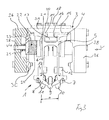
- Fig. 3 shows the connection arrangement in a partially sectional view.
- the busbar elements 1, 2 have an upper horizontal carrier 4 in the installed position, from which two parallel outer legs 5, 6 extend downwards.
- To the outer legs 5, 6 of the busbar element 1, 2 join inwardly extending clamping arms 7, 8, which hold a contact wire 9 by clamping outside the transition region of the busbar elements.
- the two skids 10, 11 extend at a predetermined distance a parallel to each other in the longitudinal direction of the busbar elements, wherein one end of the one skid 10 with the contact wire 9 of a busbar element 1 and one end of the other running skids 11 overlaps with the contact wire 9 of the other busbar element 2 and the other ends of the skids 10, 11 overlap each other, so that the contact wire route is not interrupted.
- the upper support 4 of the first busbar element 1 rests with the interposition of sliding elements 14, 15 on the underside of the middle leg 3A of the connection profile 3.
- the carrier 4 has at the top a extending in the longitudinal direction of the busbar element recess 16 into which a guide plate 17 is inserted.
- the guide plate 17 is screwed with guide pin 18 such that the upper carrier 4 of the busbar element 1 and the connecting profile 3 are connected to each other in the longitudinal direction displaceable.
- the outer legs 3A, 3B of the connection profile 3 laterally comprise the outer legs 5, 6 of the busbar elements 1, 2.
- connection profile 3 The electrical connection of the first busbar element 1 to the one end of the connection profile 3 will be described below.
- a contact rail 21 which extends in the longitudinal direction of the busbar element 1.
- a contact rail 21 which extends in the longitudinal direction of the busbar element 1.
- the contact elements 22 on both sides of the busbar element 1 each have an outer contact plate 23, on which an inner contact piece 24, in particular a metal carbon is fixed, which contacts with the associated contact rail 21.
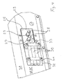
- connection profile 3 contact plates 23 are resiliently biased against the contact rails 21 ( Fig. 4 ).
- the lateral recesses 25 of the connection profile 3 are sealed with housing parts 26.
- the bias voltage is applied to seated on guide pins 28 springs 29, which are supported on the one hand on the inside of the housing parts 26 and on the other hand on the contact plates 23 ( Fig. 4 ).
- the other ends of the copper cables 30 are electrically connected to the contact plates 23 attached to the contact plates 23 clamping members 33 with the contact plates 23, so that the current from the contact plates 23 via the copper cables 30 to the Connection profile 3 can flow, which is electrically connected to the second busbar element 2.
- connection profile 3 and the second busbar element 2 is not critical, since the second busbar element 2 and the connection profile 3 can not move relative to one another.
- the electrical connection can be designed differently. Both components can be screwed together to produce the electrical connection.
Landscapes
- Engineering & Computer Science (AREA)
- Mechanical Engineering (AREA)
- Current-Collector Devices For Electrically Propelled Vehicles (AREA)
- Supply And Distribution Of Alternating Current (AREA)
Priority Applications (2)
| Application Number | Priority Date | Filing Date | Title |
|---|---|---|---|
| PL14185236T PL2851235T3 (pl) | 2013-09-23 | 2014-09-17 | Układ do łączenia elementów szyn energetycznych sieci trakcyjnej |
| HRP20201716TT HRP20201716T1 (hr) | 2013-09-23 | 2020-10-23 | Uređaj za spajanje elemenata elektrificiranih tračnica kod kontaktnog sustava voznih vodova |
Applications Claiming Priority (1)
| Application Number | Priority Date | Filing Date | Title |
|---|---|---|---|
| DE102013015874.5A DE102013015874B3 (de) | 2013-09-23 | 2013-09-23 | Anordnung zum Verbinden von Stromschienen-Elementen eines Fahrleitungssystems |
Publications (3)
| Publication Number | Publication Date |
|---|---|
| EP2851235A2 true EP2851235A2 (fr) | 2015-03-25 |
| EP2851235A3 EP2851235A3 (fr) | 2015-10-21 |
| EP2851235B1 EP2851235B1 (fr) | 2020-08-26 |
Family
ID=51584965
Family Applications (1)
| Application Number | Title | Priority Date | Filing Date |
|---|---|---|---|
| EP14185236.8A Active EP2851235B1 (fr) | 2013-09-23 | 2014-09-17 | Agencement destiné à relier des éléments de rails conducteurs d'un système de caténaires |
Country Status (10)
| Country | Link |
|---|---|
| EP (1) | EP2851235B1 (fr) |
| KR (1) | KR102293167B1 (fr) |
| DE (1) | DE102013015874B3 (fr) |
| DK (1) | DK2851235T3 (fr) |
| ES (1) | ES2831608T3 (fr) |
| HR (1) | HRP20201716T1 (fr) |
| HU (1) | HUE050982T2 (fr) |
| LT (1) | LT2851235T (fr) |
| PL (1) | PL2851235T3 (fr) |
| PT (1) | PT2851235T (fr) |
Cited By (1)
| Publication number | Priority date | Publication date | Assignee | Title |
|---|---|---|---|---|
| CN117962703A (zh) * | 2024-04-01 | 2024-05-03 | 中铁建电气化局集团轨道交通器材有限公司 | 一种刚性接触网导线局部磨损的修正装置 |
Families Citing this family (2)
| Publication number | Priority date | Publication date | Assignee | Title |
|---|---|---|---|---|
| CN105128702B (zh) * | 2015-08-26 | 2017-08-08 | 苏州东玉华电气有限公司 | 一种无卡阻刚性悬挂接触网汇流排导滑系列装置 |
| DE102017115137A1 (de) * | 2017-07-06 | 2019-01-10 | Dr. Ing. H.C. F. Porsche Aktiengesellschaft | Kontaktschieneneinrichtung für ein wenigstens teilweise elektrisch angetriebenes Fahrzeug |
Citations (1)
| Publication number | Priority date | Publication date | Assignee | Title |
|---|---|---|---|---|
| WO2012130582A2 (fr) | 2011-03-29 | 2012-10-04 | Siemens Aktiengesellschaft | Ensemble joint de dilatation de rails conducteurs contigus d'un système à ligne de contact aérienne pour véhicules automoteurs électriques |
Family Cites Families (7)
| Publication number | Priority date | Publication date | Assignee | Title |
|---|---|---|---|---|
| JP3322013B2 (ja) * | 1993-11-26 | 2002-09-09 | 日立電線株式会社 | トロリー導体用接続装置 |
| JPH11192864A (ja) * | 1998-01-05 | 1999-07-21 | Furukawa Electric Co Ltd:The | 絶縁トロリの伸縮接続部 |
| JP2000318493A (ja) * | 1999-05-10 | 2000-11-21 | Sumitomo Electric Ind Ltd | 剛体電車線用接合構造 |
| KR100611048B1 (ko) * | 2004-11-23 | 2006-08-09 | 한국철도공사 | 전차선 구분장치의 스키드 |
| CN101746281B (zh) * | 2010-01-30 | 2012-05-23 | 浙江旺隆轨道交通设备有限公司 | 一种刚性接触网膨胀接头 |
| CN201604537U (zh) * | 2010-01-30 | 2010-10-13 | 浙江旺隆轨道交通设备有限公司 | 一种膨胀接头内导电轨的电连接结构 |
| DE102012000117B3 (de) * | 2012-01-05 | 2013-04-04 | Bicc Holdings Gmbh | Stromschiene |
-
2013
- 2013-09-23 DE DE102013015874.5A patent/DE102013015874B3/de not_active Expired - Fee Related
-
2014
- 2014-09-05 KR KR1020140118799A patent/KR102293167B1/ko active Active
- 2014-09-17 PL PL14185236T patent/PL2851235T3/pl unknown
- 2014-09-17 EP EP14185236.8A patent/EP2851235B1/fr active Active
- 2014-09-17 LT LTEP14185236.8T patent/LT2851235T/lt unknown
- 2014-09-17 HU HUE14185236A patent/HUE050982T2/hu unknown
- 2014-09-17 ES ES14185236T patent/ES2831608T3/es active Active
- 2014-09-17 DK DK14185236.8T patent/DK2851235T3/da active
- 2014-09-17 PT PT141852368T patent/PT2851235T/pt unknown
-
2020
- 2020-10-23 HR HRP20201716TT patent/HRP20201716T1/hr unknown
Patent Citations (1)
| Publication number | Priority date | Publication date | Assignee | Title |
|---|---|---|---|---|
| WO2012130582A2 (fr) | 2011-03-29 | 2012-10-04 | Siemens Aktiengesellschaft | Ensemble joint de dilatation de rails conducteurs contigus d'un système à ligne de contact aérienne pour véhicules automoteurs électriques |
Cited By (2)
| Publication number | Priority date | Publication date | Assignee | Title |
|---|---|---|---|---|
| CN117962703A (zh) * | 2024-04-01 | 2024-05-03 | 中铁建电气化局集团轨道交通器材有限公司 | 一种刚性接触网导线局部磨损的修正装置 |
| CN117962703B (zh) * | 2024-04-01 | 2024-05-28 | 中铁建电气化局集团轨道交通器材有限公司 | 一种刚性接触网导线局部磨损的修正装置 |
Also Published As
| Publication number | Publication date |
|---|---|
| PL2851235T3 (pl) | 2021-03-08 |
| KR102293167B1 (ko) | 2021-08-25 |
| HRP20201716T1 (hr) | 2020-12-25 |
| PT2851235T (pt) | 2020-09-03 |
| EP2851235B1 (fr) | 2020-08-26 |
| KR20150033539A (ko) | 2015-04-01 |
| HUE050982T2 (hu) | 2021-01-28 |
| EP2851235A3 (fr) | 2015-10-21 |
| DE102013015874B3 (de) | 2015-02-12 |
| DK2851235T3 (da) | 2020-11-23 |
| ES2831608T3 (es) | 2021-06-09 |
| LT2851235T (lt) | 2020-10-12 |
Similar Documents
| Publication | Publication Date | Title |
|---|---|---|
| DE102017100039A1 (de) | Elektrische Sammelschienenleitungsverbindung mit Längeneinstelleinrichtung | |
| DE102017100143A1 (de) | Elektrische Sammelschienenleitungsverbindung mit selbsteinstellenden Stützen | |
| EP2363314B1 (fr) | Dispositif de couplage de systèmes de caténaires électriques et fixes | |
| EP2805847B1 (fr) | Dispositif avec deux rails conducteurs fixes et un séparateur de voies | |
| DE102017100140A1 (de) | Elektrische Sammelschienenleitungsverbindung mit externen Schraubklemmstützen | |
| DE102017100142A1 (de) | Verstellbare elektrische Sammelschienenleitungsverbindung mit gegabelten Sammelschienen | |
| DE102014114828B4 (de) | Anordnung mit einem Leistungshalbleitermodul, mit einer Gleichspannungsverschienung und mit einer Kondensatoreinrichtung | |
| EP3446384B1 (fr) | Système d'entraînement comprenant une barre conductrice de circuit intermédiaire | |
| EP2612788B1 (fr) | dispositif de suspension d'un ligne de contact | |
| DE102013015874B3 (de) | Anordnung zum Verbinden von Stromschienen-Elementen eines Fahrleitungssystems | |
| EP2691256B1 (fr) | Ensemble joint de dilatation de rails conducteurs contigus d'un système à ligne de contact aérienne pour véhicules automoteurs électriques | |
| EP4204254B1 (fr) | Dispositif pour compenser une modification de longueur d'un rail conducteur | |
| EP3480054B1 (fr) | Séparations électriques à l'intérieur des rails conducteurs du plafond | |
| DE102017130205B3 (de) | Elektrische Trennungen in Deckenstromschienen | |
| DE19631995A1 (de) | System zum Verbinden einer Weicheisenstromschiene mit einem Stromleiter | |
| DE2654073C2 (de) | StTomschienenanlage für spurgebundene Transportmittel, insbesondere elektrische Bahnen | |
| DE102014208280A1 (de) | Energieverteilungseinrichtung zur elektrischen Energieverteilung für eine Mittelspannungs- oder Hochspannungs-Schaltungsanlage | |
| DE4023914C2 (fr) | ||
| WO2025168324A1 (fr) | Système de charge rapide et procédé de connexion électrique d'un véhicule à une station de charge | |
| DE102017216781A1 (de) | Befestigungssystem zur Befestigung von Batteriemodulen in einem Batteriegehäuse | |
| DE102024127898A1 (de) | Dehnverbindungsvorrichtung und Schleifleitungssystem | |
| AT16844B (de) | Stromabnehmer für elektrisch betriebene Fahrzeuge. | |
| DE102020134830A1 (de) | Fahrweg für ein Fahrzeug und Schienenanordnung eines Fahrwegs | |
| DE1540649A1 (de) | Sammelschienensystem | |
| DE102018126319A1 (de) | Lasttragelement |
Legal Events
| Date | Code | Title | Description |
|---|---|---|---|
| PUAI | Public reference made under article 153(3) epc to a published international application that has entered the european phase |
Free format text: ORIGINAL CODE: 0009012 |
|
| 17P | Request for examination filed |
Effective date: 20140917 |
|
| AK | Designated contracting states |
Kind code of ref document: A2 Designated state(s): AL AT BE BG CH CY CZ DE DK EE ES FI FR GB GR HR HU IE IS IT LI LT LU LV MC MK MT NL NO PL PT RO RS SE SI SK SM TR |
|
| AX | Request for extension of the european patent |
Extension state: BA ME |
|
| PUAL | Search report despatched |
Free format text: ORIGINAL CODE: 0009013 |
|
| AK | Designated contracting states |
Kind code of ref document: A3 Designated state(s): AL AT BE BG CH CY CZ DE DK EE ES FI FR GB GR HR HU IE IS IT LI LT LU LV MC MK MT NL NO PL PT RO RS SE SI SK SM TR |
|
| AX | Request for extension of the european patent |
Extension state: BA ME |
|
| RIC1 | Information provided on ipc code assigned before grant |
Ipc: B60M 1/30 20060101AFI20150917BHEP |
|
| RAP1 | Party data changed (applicant data changed or rights of an application transferred) |
Owner name: RAIL POWER SYSTEMS GMBH |
|
| R17P | Request for examination filed (corrected) |
Effective date: 20160421 |
|
| RBV | Designated contracting states (corrected) |
Designated state(s): AL AT BE BG CH CY CZ DE DK EE ES FI FR GB GR HR HU IE IS IT LI LT LU LV MC MK MT NL NO PL PT RO RS SE SI SK SM TR |
|
| STAA | Information on the status of an ep patent application or granted ep patent |
Free format text: STATUS: EXAMINATION IS IN PROGRESS |
|
| 17Q | First examination report despatched |
Effective date: 20180601 |
|
| GRAP | Despatch of communication of intention to grant a patent |
Free format text: ORIGINAL CODE: EPIDOSNIGR1 |
|
| STAA | Information on the status of an ep patent application or granted ep patent |
Free format text: STATUS: GRANT OF PATENT IS INTENDED |
|
| INTG | Intention to grant announced |
Effective date: 20200415 |
|
| GRAS | Grant fee paid |
Free format text: ORIGINAL CODE: EPIDOSNIGR3 |
|
| GRAA | (expected) grant |
Free format text: ORIGINAL CODE: 0009210 |
|
| STAA | Information on the status of an ep patent application or granted ep patent |
Free format text: STATUS: THE PATENT HAS BEEN GRANTED |
|
| AK | Designated contracting states |
Kind code of ref document: B1 Designated state(s): AL AT BE BG CH CY CZ DE DK EE ES FI FR GB GR HR HU IE IS IT LI LT LU LV MC MK MT NL NO PL PT RO RS SE SI SK SM TR |
|
| REG | Reference to a national code |
Ref country code: GB Ref legal event code: FG4D Free format text: NOT ENGLISH |
|
| REG | Reference to a national code |
Ref country code: CH Ref legal event code: EP |
|
| REG | Reference to a national code |
Ref country code: PT Ref legal event code: SC4A Ref document number: 2851235 Country of ref document: PT Date of ref document: 20200903 Kind code of ref document: T Free format text: AVAILABILITY OF NATIONAL TRANSLATION Effective date: 20200827 |
|
| REG | Reference to a national code |
Ref country code: AT Ref legal event code: REF Ref document number: 1306056 Country of ref document: AT Kind code of ref document: T Effective date: 20200915 |
|
| REG | Reference to a national code |
Ref country code: IE Ref legal event code: FG4D Free format text: LANGUAGE OF EP DOCUMENT: GERMAN |
|
| REG | Reference to a national code |
Ref country code: DE Ref legal event code: R096 Ref document number: 502014014663 Country of ref document: DE |
|
| REG | Reference to a national code |
Ref country code: SE Ref legal event code: TRGR |
|
| REG | Reference to a national code |
Ref country code: CH Ref legal event code: NV Representative=s name: AMMANN PATENTANWAELTE AG BERN, CH |
|
| REG | Reference to a national code |
Ref country code: GR Ref legal event code: EP Ref document number: 20200402585 Country of ref document: GR Effective date: 20201014 |
|
| REG | Reference to a national code |
Ref country code: HR Ref legal event code: TUEP Ref document number: P20201716 Country of ref document: HR |
|
| REG | Reference to a national code |
Ref country code: EE Ref legal event code: FG4A Ref document number: E019720 Country of ref document: EE Effective date: 20200930 |
|
| REG | Reference to a national code |
Ref country code: FI Ref legal event code: FGE |
|
| REG | Reference to a national code |
Ref country code: RO Ref legal event code: EPE |
|
| REG | Reference to a national code |
Ref country code: DK Ref legal event code: T3 Effective date: 20201119 |
|
| REG | Reference to a national code |
Ref country code: NL Ref legal event code: FP |
|
| REG | Reference to a national code |
Ref country code: HR Ref legal event code: ODRP Ref document number: P20201716 Country of ref document: HR Payment date: 20201023 Year of fee payment: 7 |
|
| REG | Reference to a national code |
Ref country code: HR Ref legal event code: T1PR Ref document number: P20201716 Country of ref document: HR |
|
| REG | Reference to a national code |
Ref country code: HU Ref legal event code: AG4A Ref document number: E050982 Country of ref document: HU |
|
| REG | Reference to a national code |
Ref country code: NO Ref legal event code: T2 Effective date: 20200826 |
|
| PG25 | Lapsed in a contracting state [announced via postgrant information from national office to epo] |
Ref country code: RS Free format text: LAPSE BECAUSE OF FAILURE TO SUBMIT A TRANSLATION OF THE DESCRIPTION OR TO PAY THE FEE WITHIN THE PRESCRIBED TIME-LIMIT Effective date: 20200826 Ref country code: IS Free format text: LAPSE BECAUSE OF FAILURE TO SUBMIT A TRANSLATION OF THE DESCRIPTION OR TO PAY THE FEE WITHIN THE PRESCRIBED TIME-LIMIT Effective date: 20201226 |
|
| REG | Reference to a national code |
Ref country code: SK Ref legal event code: T3 Ref document number: E 36427 Country of ref document: SK |
|
| PG25 | Lapsed in a contracting state [announced via postgrant information from national office to epo] |
Ref country code: SM Free format text: LAPSE BECAUSE OF FAILURE TO SUBMIT A TRANSLATION OF THE DESCRIPTION OR TO PAY THE FEE WITHIN THE PRESCRIBED TIME-LIMIT Effective date: 20200826 |
|
| REG | Reference to a national code |
Ref country code: DE Ref legal event code: R097 Ref document number: 502014014663 Country of ref document: DE |
|
| PG25 | Lapsed in a contracting state [announced via postgrant information from national office to epo] |
Ref country code: MC Free format text: LAPSE BECAUSE OF FAILURE TO SUBMIT A TRANSLATION OF THE DESCRIPTION OR TO PAY THE FEE WITHIN THE PRESCRIBED TIME-LIMIT Effective date: 20200826 Ref country code: AL Free format text: LAPSE BECAUSE OF FAILURE TO SUBMIT A TRANSLATION OF THE DESCRIPTION OR TO PAY THE FEE WITHIN THE PRESCRIBED TIME-LIMIT Effective date: 20200826 |
|
| REG | Reference to a national code |
Ref country code: ES Ref legal event code: FG2A Ref document number: 2831608 Country of ref document: ES Kind code of ref document: T3 Effective date: 20210609 |
|
| PLBE | No opposition filed within time limit |
Free format text: ORIGINAL CODE: 0009261 |
|
| STAA | Information on the status of an ep patent application or granted ep patent |
Free format text: STATUS: NO OPPOSITION FILED WITHIN TIME LIMIT |
|
| 26N | No opposition filed |
Effective date: 20210527 |
|
| PG25 | Lapsed in a contracting state [announced via postgrant information from national office to epo] |
Ref country code: SI Free format text: LAPSE BECAUSE OF FAILURE TO SUBMIT A TRANSLATION OF THE DESCRIPTION OR TO PAY THE FEE WITHIN THE PRESCRIBED TIME-LIMIT Effective date: 20200826 |
|
| REG | Reference to a national code |
Ref country code: HR Ref legal event code: ODRP Ref document number: P20201716 Country of ref document: HR Payment date: 20210908 Year of fee payment: 8 |
|
| PG25 | Lapsed in a contracting state [announced via postgrant information from national office to epo] |
Ref country code: MT Free format text: LAPSE BECAUSE OF FAILURE TO SUBMIT A TRANSLATION OF THE DESCRIPTION OR TO PAY THE FEE WITHIN THE PRESCRIBED TIME-LIMIT Effective date: 20200826 Ref country code: CY Free format text: LAPSE BECAUSE OF FAILURE TO SUBMIT A TRANSLATION OF THE DESCRIPTION OR TO PAY THE FEE WITHIN THE PRESCRIBED TIME-LIMIT Effective date: 20200826 |
|
| PG25 | Lapsed in a contracting state [announced via postgrant information from national office to epo] |
Ref country code: MK Free format text: LAPSE BECAUSE OF FAILURE TO SUBMIT A TRANSLATION OF THE DESCRIPTION OR TO PAY THE FEE WITHIN THE PRESCRIBED TIME-LIMIT Effective date: 20200826 |
|
| REG | Reference to a national code |
Ref country code: HR Ref legal event code: ODRP Ref document number: P20201716 Country of ref document: HR Payment date: 20220907 Year of fee payment: 9 |
|
| REG | Reference to a national code |
Ref country code: HR Ref legal event code: ODRP Ref document number: P20201716 Country of ref document: HR Payment date: 20230904 Year of fee payment: 10 |
|
| REG | Reference to a national code |
Ref country code: HR Ref legal event code: ODRP Ref document number: P20201716 Country of ref document: HR Payment date: 20240913 Year of fee payment: 11 |
|
| PGFP | Annual fee paid to national office [announced via postgrant information from national office to epo] |
Ref country code: BG Payment date: 20240917 Year of fee payment: 11 |
|
| PGFP | Annual fee paid to national office [announced via postgrant information from national office to epo] |
Ref country code: FI Payment date: 20240919 Year of fee payment: 11 Ref country code: HR Payment date: 20240913 Year of fee payment: 11 Ref country code: IE Payment date: 20240919 Year of fee payment: 11 Ref country code: LT Payment date: 20240903 Year of fee payment: 11 |
|
| PGFP | Annual fee paid to national office [announced via postgrant information from national office to epo] |
Ref country code: GR Payment date: 20240918 Year of fee payment: 11 Ref country code: DK Payment date: 20240920 Year of fee payment: 11 |
|
| PGFP | Annual fee paid to national office [announced via postgrant information from national office to epo] |
Ref country code: GB Payment date: 20240923 Year of fee payment: 11 Ref country code: PT Payment date: 20240905 Year of fee payment: 11 |
|
| PGFP | Annual fee paid to national office [announced via postgrant information from national office to epo] |
Ref country code: BE Payment date: 20240920 Year of fee payment: 11 Ref country code: LU Payment date: 20240919 Year of fee payment: 11 |
|
| PGFP | Annual fee paid to national office [announced via postgrant information from national office to epo] |
Ref country code: NL Payment date: 20240920 Year of fee payment: 11 |
|
| PGFP | Annual fee paid to national office [announced via postgrant information from national office to epo] |
Ref country code: EE Payment date: 20240917 Year of fee payment: 11 Ref country code: CZ Payment date: 20240904 Year of fee payment: 11 |
|
| PGFP | Annual fee paid to national office [announced via postgrant information from national office to epo] |
Ref country code: SK Payment date: 20240905 Year of fee payment: 11 Ref country code: HU Payment date: 20240916 Year of fee payment: 11 |
|
| PGFP | Annual fee paid to national office [announced via postgrant information from national office to epo] |
Ref country code: LV Payment date: 20240918 Year of fee payment: 11 |
|
| PGFP | Annual fee paid to national office [announced via postgrant information from national office to epo] |
Ref country code: RO Payment date: 20240905 Year of fee payment: 11 Ref country code: NO Payment date: 20240919 Year of fee payment: 11 Ref country code: SE Payment date: 20240923 Year of fee payment: 11 |
|
| PGFP | Annual fee paid to national office [announced via postgrant information from national office to epo] |
Ref country code: TR Payment date: 20240906 Year of fee payment: 11 |
|
| PGFP | Annual fee paid to national office [announced via postgrant information from national office to epo] |
Ref country code: ES Payment date: 20241018 Year of fee payment: 11 |
|
| REG | Reference to a national code |
Ref country code: CH Ref legal event code: U11 Free format text: ST27 STATUS EVENT CODE: U-0-0-U10-U11 (AS PROVIDED BY THE NATIONAL OFFICE) Effective date: 20251001 |
|
| PGFP | Annual fee paid to national office [announced via postgrant information from national office to epo] |
Ref country code: PL Payment date: 20250905 Year of fee payment: 12 |
|
| PGFP | Annual fee paid to national office [announced via postgrant information from national office to epo] |
Ref country code: FR Payment date: 20250925 Year of fee payment: 12 Ref country code: AT Payment date: 20250918 Year of fee payment: 12 |
|
| PGFP | Annual fee paid to national office [announced via postgrant information from national office to epo] |
Ref country code: DE Payment date: 20250925 Year of fee payment: 12 |
|
| PGFP | Annual fee paid to national office [announced via postgrant information from national office to epo] |
Ref country code: IT Payment date: 20250930 Year of fee payment: 12 |
|
| PGFP | Annual fee paid to national office [announced via postgrant information from national office to epo] |
Ref country code: CH Payment date: 20251001 Year of fee payment: 12 |
|
| REG | Reference to a national code |
Ref country code: HR Ref legal event code: PBON Ref document number: P20201716 Country of ref document: HR Effective date: 20250917 |
|
| REG | Reference to a national code |
Ref country code: LT Ref legal event code: MM4D Effective date: 20250917 |
|
| PG25 | Lapsed in a contracting state [announced via postgrant information from national office to epo] |
Ref country code: FI Free format text: LAPSE BECAUSE OF NON-PAYMENT OF DUE FEES Effective date: 20250917 |
|
| PG25 | Lapsed in a contracting state [announced via postgrant information from national office to epo] |
Ref country code: RO Free format text: LAPSE BECAUSE OF NON-PAYMENT OF DUE FEES Effective date: 20250917 |
|
| REG | Reference to a national code |
Ref country code: DK Ref legal event code: EBP Effective date: 20250930 |
|
| PG25 | Lapsed in a contracting state [announced via postgrant information from national office to epo] |
Ref country code: PT Free format text: LAPSE BECAUSE OF NON-PAYMENT OF DUE FEES Effective date: 20260317 Ref country code: CZ Free format text: LAPSE BECAUSE OF NON-PAYMENT OF DUE FEES Effective date: 20250917 |
|
| PG25 | Lapsed in a contracting state [announced via postgrant information from national office to epo] |
Ref country code: LV Free format text: LAPSE BECAUSE OF NON-PAYMENT OF DUE FEES Effective date: 20250917 |
|
| REG | Reference to a national code |
Ref country code: SK Ref legal event code: MM4A Ref document number: E 36427 Country of ref document: SK Effective date: 20250917 |