EP2851246B1 - Verfahren zur Erfassung der Position eines Wischarms einer Scheibenwischervorrichtung - Google Patents
Verfahren zur Erfassung der Position eines Wischarms einer Scheibenwischervorrichtung Download PDFInfo
- Publication number
- EP2851246B1 EP2851246B1 EP14184477.9A EP14184477A EP2851246B1 EP 2851246 B1 EP2851246 B1 EP 2851246B1 EP 14184477 A EP14184477 A EP 14184477A EP 2851246 B1 EP2851246 B1 EP 2851246B1
- Authority
- EP
- European Patent Office
- Prior art keywords
- window
- wiper arm
- motor
- wiper
- maintenance
- Prior art date
- Legal status (The legal status is an assumption and is not a legal conclusion. Google has not performed a legal analysis and makes no representation as to the accuracy of the status listed.)
- Active
Links
Images
Classifications
-
- H—ELECTRICITY
- H02—GENERATION; CONVERSION OR DISTRIBUTION OF ELECTRIC POWER
- H02P—CONTROL OR REGULATION OF ELECTRIC MOTORS, ELECTRIC GENERATORS OR DYNAMO-ELECTRIC CONVERTERS; CONTROLLING TRANSFORMERS, REACTORS OR CHOKE COILS
- H02P3/00—Arrangements for stopping or slowing electric motors, generators, or dynamo-electric converters
- H02P3/06—Arrangements for stopping or slowing electric motors, generators, or dynamo-electric converters for stopping or slowing an individual dynamo-electric motor or dynamo-electric converter
- H02P3/08—Arrangements for stopping or slowing electric motors, generators, or dynamo-electric converters for stopping or slowing an individual dynamo-electric motor or dynamo-electric converter for stopping or slowing a DC motor
-
- B—PERFORMING OPERATIONS; TRANSPORTING
- B60—VEHICLES IN GENERAL
- B60S—SERVICING, CLEANING, REPAIRING, SUPPORTING, LIFTING, OR MANOEUVRING OF VEHICLES, NOT OTHERWISE PROVIDED FOR
- B60S1/00—Cleaning of vehicles
- B60S1/02—Cleaning windscreens, windows or optical devices
- B60S1/04—Wipers or the like, e.g. scrapers
- B60S1/0452—Position of the wipers relative to the vehicle
-
- B—PERFORMING OPERATIONS; TRANSPORTING
- B60—VEHICLES IN GENERAL
- B60S—SERVICING, CLEANING, REPAIRING, SUPPORTING, LIFTING, OR MANOEUVRING OF VEHICLES, NOT OTHERWISE PROVIDED FOR
- B60S1/00—Cleaning of vehicles
- B60S1/02—Cleaning windscreens, windows or optical devices
- B60S1/04—Wipers or the like, e.g. scrapers
- B60S1/06—Wipers or the like, e.g. scrapers characterised by the drive
- B60S1/08—Wipers or the like, e.g. scrapers characterised by the drive electrically driven
-
- B—PERFORMING OPERATIONS; TRANSPORTING
- B60—VEHICLES IN GENERAL
- B60S—SERVICING, CLEANING, REPAIRING, SUPPORTING, LIFTING, OR MANOEUVRING OF VEHICLES, NOT OTHERWISE PROVIDED FOR
- B60S1/00—Cleaning of vehicles
- B60S1/02—Cleaning windscreens, windows or optical devices
- B60S1/04—Wipers or the like, e.g. scrapers
- B60S1/32—Wipers or the like, e.g. scrapers characterised by constructional features of wiper blade arms or blades
- B60S1/34—Wiper arms; Mountings therefor
- B60S1/3413—Wiper arms; Mountings therefor with means for holding the arm off the glass in an intermediate position between the working position and the fully folded back position
Definitions
- the present invention relates to a method for detecting the position of a brush holder for a wiper system of a vehicle window.
- a vehicle windscreen wiper system comprises in particular at least one wiper blade carried by a brush holder and a drive motor of the brush holder so that the wiper is driven by the brush holder wiping the windshield, in a cyclic rotational movement, substantially in a portion of a circle, about an axis of rotation.
- the brush holder comprises an articulated end on a portion of the vehicle and is movable, generally manually, from a so-called service position in which the brush that it carries is in contact with the windshield and is adapted to be driven by the wiper holder for wiping the windshield, and a maintenance position in which the wiper is not in contact with the windshield.
- the brush holder can be put in the maintenance position for example to clean the brush, replace it in case of wear or protect it from frost formed on the windshield in winter.
- This problem particularly concerns the type of wiper system for which the brush holder is in a storage position, for example under the hood of the vehicle, when the system is inactive.
- the brush holder is not accessible in this storage position and can not be brought directly from this position to a position of maintenance.
- a specific control of the system from the passenger compartment of the vehicle, makes it possible to move the brush holder from its storage position to an intermediate position in which it is accessible and the broom which it carries rests on the windshield. The brush holder can then be moved manually from this intermediate position to a maintenance position in which the brush is no longer in contact with the windshield.
- the invention proposes a simple, effective and economical solution to the aforementioned problem.
- said parameter is chosen from the electrical consumption of said motor, the output torque of said motor, the friction torque of said wiper blade on said window and the coefficient of friction of said wiper blade on said window.
- the invention thus proposes a method for determining whether or not a wiper blade is in contact with a window of a vehicle, the wiper being in contact with the window when the wiper holder is in the so-called service position (or intermediate) and is not in contact with the window when the brush holder is in the maintenance position.
- at least one parameter is studied, the study of this parameter being to study the effort required for the wiper system to move the broom. Comparing the measured or estimated value to the value or range of reference values makes it easy to determine whether or not the brush holder is in its maintenance position. Management of the result of this comparison can alert the driver in the passenger compartment, interrupt or block the actuation of the engine.
- the parameter studied is advantageously estimated (and not calculated) to avoid equipping the system with a sensor for measuring this parameter.
- the steps a) to c) of the method can follow the reception by the control unit of a drive order of said brush holder, emitted for example from the passenger compartment of the vehicle.
- the system can check the position of the brush holder to avoid the risk of system destruction.
- Steps a) to c) of the process are preferably carried out at a time t.
- the estimation of the parameter is then not performed for a period of time but instead is performed instantaneously.
- Steps a) to c) can precede or follow directly a step of starting the drive of said brush holder, preferably directly follow a step of starting the drive of the brush holder.
- step e) In the case where steps a) to c) of the method are carried out before driving the brush holder, this drive can be blocked / prevented (step e) if the result in step c) indicates that the carrier broom is in its maintenance position. In the case where steps a) to c) are performed after a start of training the brush holder (which would be detected by step d)), this training can be interrupted (step e) if the result of step c) indicates that the brush holder is in its maintenance position.
- the parameter is estimated and compared by the control unit of the wiper system.
- the chosen parameter is the coefficient of friction of said wiper blade on said window.
- the step of comparing the method therefore consists in comparing an estimated value of the coefficient of friction with a value or a range of reference values.
- the control unit can deduce that the brush holder is in its maintenance position and therefore that the blade is not in contact with the window.
- the latter may range from zero to a threshold value, which is the minimum value of the coefficient of friction of said wiper blade on said window, in particular when said window is wet.
- This threshold value can be determined empirically. Alternatively, the threshold value can be determined by simulation or tribology.
- a value of the coefficient of friction can be estimated from an estimated value of the output torque of the engine, which can itself be estimated from an estimated value of the electrical consumption of the engine. All these estimates can be made by the control unit of the wiper system. Estimates of values are preferably instantaneous estimates, that is, made at time t.
- the present invention also relates to a wiper system as defined above, wherein said control unit for the motor control comprises said device adapted to perform the steps a) to c) mentioned above.
- the invention also relates to a wiper system according to any one of the above definitions, wherein said device is able to implement the method of detecting the position of a brush holder according to any one of variants defined above.
- the invention also relates to a vehicle, in particular an automobile, characterized in that it comprises at least one wiper system according to any one of the variants defined above.
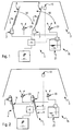
- Figures 1 and 2 represent the same wiper system 1 of a vehicle window 3, in particular of a windshield of an automobile, this system comprising here two wipers 4 for wiping the window 3, which are each carried by a broom holder 5.
- Each brush holder 5 has an end connected to a motor 7 which is intended to drive the brush holder 5 by wiping the window 3 in a cyclic rotational movement, substantially in a portion of a circle, about an axis of rotation. .
- each motor 7 comprises an output shaft which transmits a drive torque to the brush holder 5, for example via a linkage.
- the motors 7 are electric and are connected to an electrical source 11, such as the vehicle battery or an alternator, through a control unit 9 of the system 1.
- This unit 9 is configured to manage the operation of the system 1 according to several predefined programs, for example by controlling the speed W of rotation of the brush holder 5 from the regulation of the current delivered to the motors 7, for a given voltage value.
- the wiper system 1 here comprises a rain sensor 13 connected to the control unit 9. It also comprises a device 15 for cleaning the window 3, which comprises a pump 17 connected to the unit 9 and configured to take off windshield washer fluid 19 of a container 21 and route it to the liquid projection means on the window 3, these projection means being for example nozzles 23 mounted on the hood of the vehicle.
- the brush holders 5 are shown in their service position in figure 1 and in their maintenance position in figure 2 . In their operating position, the brush holders 5 are folded towards the window 3 and the brushes 4 are in contact with the window 3. In this position, the brush holders 5 can be moved by actuating the motors 7, so that the brooms 4 wipe the window 3.
- the brush holders 5 are spaced from the window 3 and the brushes 4 are away from the window and are therefore not in contact with the latter. In this position, the brushes 4 can be cleaned or removed from the brush holders 5 to replace them with new ones.
- the present invention proposes in particular a method for detecting whether the brush holders 5 are in their service position or in their maintenance position, in order to limit the risks of degradation of the system 1, in particular during its activation.
- the unit 9 controls in particular the drive speed W of the brush holders 5 from the control of the electric supply current of the motors 7, for a given voltage value.
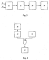
- the unit 9 is furthermore configured to predict, in particular from a given voltage value (reference 25 in figure 3 ) and the position of the brush holder 5 on the window 3 (reference 27), what should theoretically be the drive speed W of the brush holder 5 (step referenced 29).
- the coefficient of friction is estimated by unit 9.
- the comparison of values of the coefficient of friction and the interpretation of the result are also carried out by the unit 9.
- the estimated value of the coefficient of friction can be compared by the unit 9 to a reference value, for example zero.
- a coefficient of zero friction means that the displacement of the brush holder 5 generates no friction between the blade 4 and the window 3 and therefore that the brush holder 5 is in its maintenance position. This is only possible if the broom is not in contact with the glass.
- the control unit considers that the blade 4 is not in contact with the window 3 and that the brush holder 5 which carries the brush 4 is in a maintenance position.
- the estimated value of the coefficient of friction can be compared by the unit 9 to a range of reference values, extending for example from zero to a threshold value, as described in the foregoing.
- the threshold value may be slightly greater than zero.
- the steps of the method can be implemented by the control unit 9 as soon as it receives an activation order of the drive of the brush holder 5, from the passenger compartment of the vehicle. On receipt of this order, the unit 9 can carry out, in parallel with steps a) to c), a step 39 for detecting the displacement of the brush holders 5. In the case where the estimated value of the coefficient of friction is equal to zero and a movement of the brush holder 5 is detected, the unit 9 can interrupt this movement so as not to degrade the system (step 41).
- the unit 9 may be designed to block or prevent any displacement of the brush holders 5, from the moment when the estimated value of the coefficient of friction is equal to zero, and without a displacement of the carriers. brooms have been detected.
- Unit 9 can perform the process steps for one or both of the brush holders. It is conceivable that one of the brush holders is in service position while the other brush holder is in the maintenance position. The control unit 9 is then able to identify which of the brush holders is in its maintenance position and to block the drive of this brush holder. The drive of the other brush holder can then be kept on or interrupted.
- the parameter studied by the control unit could be the output torque of the motor or the current consumption of the motor, this parameter being able to be estimated as described in the foregoing.
Landscapes
- Engineering & Computer Science (AREA)
- Mechanical Engineering (AREA)
- Power Engineering (AREA)
- Control Of Direct Current Motors (AREA)
- Control Of Electric Motors In General (AREA)
Claims (15)
- Verfahren zur Erfassung der Position eines Wischarms (5) für ein Wischsystem (1) einer Fahrzeugscheibe (3), wobei dieses System umfasst:- mindestens ein Wischblatt (4), das von dem Wischarm (5) getragen wird, der von einer sogenannten Wartungsposition, in der das Wischblatt (4) nicht mit der Scheibe (3) in Kontakt ist, in eine sogenannte Betriebsposition, in der das Wischblatt (4) mit der Scheibe (3) in Kontakt ist, verschiebbar ist,- mindestens einen Antriebsmotor (7) des Wischarms (5), und- mindestens eine Kontrolleinheit (9) zur Steuerung des Motors (7),dadurch gekennzeichnet, dass das Verfahren die folgenden Schritte umfasst, darin bestehend:a) mindestens einen Parameter zur Bestimmung der Wartungs- oder Betriebsposition zu messen oder zu schätzen (35),b) den gemessenen oder geschätzten Wert des Parameters mit einem Referenzwert oder einem Bereich von Referenzwerten zu vergleichen (37), undc) auf Basis der Resultate des Vergleichs zu bestimmen, ob sich der Wischarm (5) in Wartungs- oder Betriebsposition befindet.
- Verfahren nach Anspruch 1, bei dem der Parameter unter dem elektrischen Verbrauch des Motors (7), dem Ausgangsdrehmoment des Motors (7), dem Reibmoment des Wischblattes (4) auf der Scheibe (3) und dem Reibbeiwert des Wischblattes (4) auf der Scheibe (3) ausgewählt ist.
- Verfahren nach Anspruch 1 oder 2, bei dem die Schritte a) bis c) auf den Erhalt eines Antriebsbefehls des Wischarms (5) von der Kontrolleinheit (9) folgen.
- Verfahren nach Anspruch 3, bei dem die Schritte a) bis c) direkt einem Schritt des Startens des Antriebs des Wischarms (5) vorhergehen oder folgen, vorzugsweise direkt einem Schritt des Startens des Antriebs des Wischarms (5) folgen.
- Verfahren nach einem der vorhergehenden Ansprüche, umfassend einen zusätzlichen Schritt (39) der Erfassung einer Bewegung des Wischarms (5).
- Verfahren nach einem der vorhergehenden Ansprüche, umfassend einen zusätzlichen Schritt (41) der Feststellung oder Unterbrechung einer Bewegung des Wischarms (5).
- Verfahren nach einem der vorhergehenden Ansprüche, bei dem der Parameter von der Kontrolleinheit (9) geschätzt und verglichen wird.
- Verfahren nach einem der vorhergehenden Ansprüche, bei dem der ausgewählte Parameter der Reibbeiwert des Wischblattes (4) auf der Scheibe (3) ist.
- Verfahren nach Anspruch 8, bei dem der Referenzwert gleich Null ist.
- Verfahren nach Anspruch 8, bei dem sich der Bereich von Referenzwerten von Null bis zu einem Schwellenwert erstreckt, der der Mindestwert des Reibbeiwerts des Wischblattes (4) auf der Scheibe (3) ist, insbesondere wenn die Scheibe (3) nass ist.
- Verfahren nach Anspruch 10, bei dem der Schwellenwert empirisch bestimmt wird.
- Verfahren nach einem der Ansprüche 8 bis 11, bei dem ein Wert des Reibbeiwerts auf Basis eines geschätzten Werts des Ausgangsdrehmoments des Motors (7) geschätzt wird.
- Verfahren nach Anspruch 12, bei dem der Wert des Ausgangsdrehmoments des Motors (7) auf Basis eines geschätzten Werts des elektrischen Verbrauchs des Motors (7) geschätzt wird.
- Verfahren nach Anspruch 12 oder 13, bei dem die Schätzungen der Werte momentane Schätzungen sind.
- Wischsystem (1) einer Fahrzeugscheibe (3), umfassend:- mindestens ein Wischblatt (4), das von dem Wischarm (5) getragen wird, der von einer sogenannten Wartungsposition, in der das Wischblatt (4) nicht mit der Scheibe (3) in Kontakt ist, in eine sogenannte Betriebsposition, in der das Wischblatt (4) mit der Scheibe (3) in Kontakt ist, verschiebbar ist,- mindestens einen Antriebsmotor (7) des Wischarms (5), und- mindestens eine Kontrolleinheit (9) zur Steuerung des Motors (7),dadurch gekennzeichnet, dass das System (1) eine Vorrichtung umfasst, die geeignet ist:a) mindestens einen Parameter zur Bestimmung der Wartungs- oder Betriebsposition zu messen oder zu schätzen (35),b) den gemessenen oder geschätzten Wert des Parameters mit einem Referenzwert oder einem Bereich von Referenzwerten zu vergleichen (37), undc) auf Basis der Resultate des Vergleichs zu bestimmen, ob sich der Wischarm (5) in Wartungs- oder Betriebsposition befindet.
Applications Claiming Priority (1)
| Application Number | Priority Date | Filing Date | Title |
|---|---|---|---|
| FR1359166A FR3010961B1 (fr) | 2013-09-24 | 2013-09-24 | Procede de detection de la position d'un porte-balai pour un systeme d'essuyage d'une vitre de vehicule |
Publications (2)
| Publication Number | Publication Date |
|---|---|
| EP2851246A1 EP2851246A1 (de) | 2015-03-25 |
| EP2851246B1 true EP2851246B1 (de) | 2016-10-05 |
Family
ID=49911658
Family Applications (1)
| Application Number | Title | Priority Date | Filing Date |
|---|---|---|---|
| EP14184477.9A Active EP2851246B1 (de) | 2013-09-24 | 2014-09-11 | Verfahren zur Erfassung der Position eines Wischarms einer Scheibenwischervorrichtung |
Country Status (3)
| Country | Link |
|---|---|
| US (1) | US9973115B2 (de) |
| EP (1) | EP2851246B1 (de) |
| FR (1) | FR3010961B1 (de) |
Families Citing this family (5)
| Publication number | Priority date | Publication date | Assignee | Title |
|---|---|---|---|---|
| FR3056784B1 (fr) * | 2016-09-28 | 2018-11-16 | Valeo Systemes D'essuyage | Procede de determination de l'usage en balayage d'un balai d'essuie-glace, et systeme d'essuyage |
| CN109297720A (zh) * | 2018-09-07 | 2019-02-01 | 江西江铃集团新能源汽车有限公司 | 雨刮系统在车身钣金上的安装强度测试方法 |
| CN113119910A (zh) * | 2020-01-10 | 2021-07-16 | 博世汽车部件(长沙)有限公司 | 雨刮器装置和用于雨刮器的控制方法 |
| CN115107707A (zh) * | 2022-06-24 | 2022-09-27 | 重庆长安汽车股份有限公司 | 一种电子雨刮控制系统 |
| CN119975256B (zh) * | 2025-03-28 | 2025-10-03 | 长城汽车股份有限公司 | 雨刮控制方法、雨刮控制装置及车辆 |
Family Cites Families (6)
| Publication number | Priority date | Publication date | Assignee | Title |
|---|---|---|---|---|
| JPH0271056U (de) * | 1988-11-17 | 1990-05-30 | ||
| FR2745540B1 (fr) * | 1996-02-29 | 1998-04-10 | Valeo Systemes Dessuyage | Dispositif de commande d'un systeme d'essuyage de vitre de vehicule |
| JP2004184264A (ja) * | 2002-12-04 | 2004-07-02 | Matsushita Electric Ind Co Ltd | 回転角度検出装置 |
| DE102005050774A1 (de) * | 2005-10-24 | 2007-04-26 | Robert Bosch Gmbh | Scheibenwischanlage mit einer im Ruhezustand eines Wischerantriebs wirksamen Selbsthemmung |
| US8453290B2 (en) * | 2006-12-26 | 2013-06-04 | Mitsuba Corporation | Wiper driving apparatus |
| US8973208B2 (en) * | 2012-01-24 | 2015-03-10 | Chrysler Group Llc | Rear wiper system |
-
2013
- 2013-09-24 FR FR1359166A patent/FR3010961B1/fr not_active Expired - Fee Related
-
2014
- 2014-09-11 EP EP14184477.9A patent/EP2851246B1/de active Active
- 2014-09-24 US US14/494,782 patent/US9973115B2/en active Active
Also Published As
| Publication number | Publication date |
|---|---|
| FR3010961B1 (fr) | 2015-10-16 |
| US20150082576A1 (en) | 2015-03-26 |
| FR3010961A1 (fr) | 2015-03-27 |
| US9973115B2 (en) | 2018-05-15 |
| EP2851246A1 (de) | 2015-03-25 |
Similar Documents
| Publication | Publication Date | Title |
|---|---|---|
| EP2851246B1 (de) | Verfahren zur Erfassung der Position eines Wischarms einer Scheibenwischervorrichtung | |
| EP3414134B1 (de) | System und verfahren zur steuerung einer vorrichtung zur reinigung einer fensterscheibe eines fahrzeugs | |
| EP1124711B1 (de) | Verfahren zum steuern eines kraftfarzeugscheibenwischers | |
| EP3532349B1 (de) | Vorrichtung und verfahren zum wischen und/oder reinigen einer glasfläche eines fahrzeugs unter verwendung einer aktiven flüssigkeit | |
| FR3040948A1 (fr) | Procede et dispositif de degivrage d’une vitre de vehicule | |
| EP3519257B1 (de) | Verfahren zur bestimmung der wischnutzung eines wischblatts und wischeranlage | |
| EP3519256B1 (de) | Verfahren zur überwachung der entwicklung des verschleisses eines wischerblattes | |
| EP1980003B1 (de) | Schutzverfahren für einen elektrischen reversiermotor | |
| EP3439926B1 (de) | Vorrichtung zum enteisen und/oder reinigen einer fahrzeugfensterscheibe mit einem motor mit kontinuierlicher rotation sowie entsprechender motor mit kontinuierlicher rotation und verfahren | |
| WO2023275259A1 (fr) | Procédé d'estimation d'un état d'usure de système de balai d'essuyage pour véhicule automobile | |
| EP3335947B1 (de) | Wischersystem für kraftfahrzeug | |
| FR2939743A3 (fr) | Systeme d'essuie-glace de vehicule automobile. | |
| WO2023275265A1 (fr) | Dispositif de détermination d'un état d'usure de balai d'essuyage | |
| EP3564078B1 (de) | Luftleitblech für kraftfahrzeug | |
| FR2957881A1 (fr) | Procede de nettoyage d'une vitre et systeme d'essuie-glace, notamment pour vehicule automobile | |
| WO2020057817A1 (fr) | Détection de neige sur une surface vitrée d'un véhicule automobile | |
| WO2018059869A1 (fr) | Procédé d'évaluation du vieillissement d'une lame d'essuyage d'un balai d'essuie-glace d'un véhicule automobile | |
| FR3041583A1 (fr) | Dispositif d'entrainement d'au moins un essuie-glace de vehicule automobile | |
| FR3058111A1 (fr) | Procede et dispositif de detection d’un balai d’essuie-glace neuf monte a la place d’un ancien balai d’essuie-glace |
Legal Events
| Date | Code | Title | Description |
|---|---|---|---|
| PUAI | Public reference made under article 153(3) epc to a published international application that has entered the european phase |
Free format text: ORIGINAL CODE: 0009012 |
|
| 17P | Request for examination filed |
Effective date: 20140911 |
|
| AK | Designated contracting states |
Kind code of ref document: A1 Designated state(s): AL AT BE BG CH CY CZ DE DK EE ES FI FR GB GR HR HU IE IS IT LI LT LU LV MC MK MT NL NO PL PT RO RS SE SI SK SM TR |
|
| AX | Request for extension of the european patent |
Extension state: BA ME |
|
| R17P | Request for examination filed (corrected) |
Effective date: 20150924 |
|
| RBV | Designated contracting states (corrected) |
Designated state(s): AL AT BE BG CH CY CZ DE DK EE ES FI FR GB GR HR HU IE IS IT LI LT LU LV MC MK MT NL NO PL PT RO RS SE SI SK SM TR |
|
| RIC1 | Information provided on ipc code assigned before grant |
Ipc: B60S 1/04 20060101ALI20160404BHEP Ipc: B60S 1/08 20060101ALI20160404BHEP Ipc: B60S 1/34 20060101AFI20160404BHEP |
|
| GRAP | Despatch of communication of intention to grant a patent |
Free format text: ORIGINAL CODE: EPIDOSNIGR1 |
|
| INTG | Intention to grant announced |
Effective date: 20160519 |
|
| GRAS | Grant fee paid |
Free format text: ORIGINAL CODE: EPIDOSNIGR3 |
|
| GRAA | (expected) grant |
Free format text: ORIGINAL CODE: 0009210 |
|
| AK | Designated contracting states |
Kind code of ref document: B1 Designated state(s): AL AT BE BG CH CY CZ DE DK EE ES FI FR GB GR HR HU IE IS IT LI LT LU LV MC MK MT NL NO PL PT RO RS SE SI SK SM TR |
|
| REG | Reference to a national code |
Ref country code: GB Ref legal event code: FG4D Free format text: NOT ENGLISH |
|
| REG | Reference to a national code |
Ref country code: CH Ref legal event code: EP |
|
| REG | Reference to a national code |
Ref country code: AT Ref legal event code: REF Ref document number: 834326 Country of ref document: AT Kind code of ref document: T Effective date: 20161015 |
|
| REG | Reference to a national code |
Ref country code: IE Ref legal event code: FG4D Free format text: LANGUAGE OF EP DOCUMENT: FRENCH |
|
| REG | Reference to a national code |
Ref country code: DE Ref legal event code: R096 Ref document number: 602014004067 Country of ref document: DE |
|
| REG | Reference to a national code |
Ref country code: NL Ref legal event code: MP Effective date: 20161005 |
|
| REG | Reference to a national code |
Ref country code: LT Ref legal event code: MG4D |
|
| PG25 | Lapsed in a contracting state [announced via postgrant information from national office to epo] |
Ref country code: LV Free format text: LAPSE BECAUSE OF FAILURE TO SUBMIT A TRANSLATION OF THE DESCRIPTION OR TO PAY THE FEE WITHIN THE PRESCRIBED TIME-LIMIT Effective date: 20161005 |
|
| REG | Reference to a national code |
Ref country code: AT Ref legal event code: MK05 Ref document number: 834326 Country of ref document: AT Kind code of ref document: T Effective date: 20161005 |
|
| PG25 | Lapsed in a contracting state [announced via postgrant information from national office to epo] |
Ref country code: SE Free format text: LAPSE BECAUSE OF FAILURE TO SUBMIT A TRANSLATION OF THE DESCRIPTION OR TO PAY THE FEE WITHIN THE PRESCRIBED TIME-LIMIT Effective date: 20161005 Ref country code: LT Free format text: LAPSE BECAUSE OF FAILURE TO SUBMIT A TRANSLATION OF THE DESCRIPTION OR TO PAY THE FEE WITHIN THE PRESCRIBED TIME-LIMIT Effective date: 20161005 Ref country code: GR Free format text: LAPSE BECAUSE OF FAILURE TO SUBMIT A TRANSLATION OF THE DESCRIPTION OR TO PAY THE FEE WITHIN THE PRESCRIBED TIME-LIMIT Effective date: 20170106 Ref country code: NO Free format text: LAPSE BECAUSE OF FAILURE TO SUBMIT A TRANSLATION OF THE DESCRIPTION OR TO PAY THE FEE WITHIN THE PRESCRIBED TIME-LIMIT Effective date: 20170105 |
|
| PG25 | Lapsed in a contracting state [announced via postgrant information from national office to epo] |
Ref country code: PL Free format text: LAPSE BECAUSE OF FAILURE TO SUBMIT A TRANSLATION OF THE DESCRIPTION OR TO PAY THE FEE WITHIN THE PRESCRIBED TIME-LIMIT Effective date: 20161005 Ref country code: IS Free format text: LAPSE BECAUSE OF FAILURE TO SUBMIT A TRANSLATION OF THE DESCRIPTION OR TO PAY THE FEE WITHIN THE PRESCRIBED TIME-LIMIT Effective date: 20170205 Ref country code: ES Free format text: LAPSE BECAUSE OF FAILURE TO SUBMIT A TRANSLATION OF THE DESCRIPTION OR TO PAY THE FEE WITHIN THE PRESCRIBED TIME-LIMIT Effective date: 20161005 Ref country code: NL Free format text: LAPSE BECAUSE OF FAILURE TO SUBMIT A TRANSLATION OF THE DESCRIPTION OR TO PAY THE FEE WITHIN THE PRESCRIBED TIME-LIMIT Effective date: 20161005 Ref country code: FI Free format text: LAPSE BECAUSE OF FAILURE TO SUBMIT A TRANSLATION OF THE DESCRIPTION OR TO PAY THE FEE WITHIN THE PRESCRIBED TIME-LIMIT Effective date: 20161005 Ref country code: RS Free format text: LAPSE BECAUSE OF FAILURE TO SUBMIT A TRANSLATION OF THE DESCRIPTION OR TO PAY THE FEE WITHIN THE PRESCRIBED TIME-LIMIT Effective date: 20161005 Ref country code: AT Free format text: LAPSE BECAUSE OF FAILURE TO SUBMIT A TRANSLATION OF THE DESCRIPTION OR TO PAY THE FEE WITHIN THE PRESCRIBED TIME-LIMIT Effective date: 20161005 Ref country code: HR Free format text: LAPSE BECAUSE OF FAILURE TO SUBMIT A TRANSLATION OF THE DESCRIPTION OR TO PAY THE FEE WITHIN THE PRESCRIBED TIME-LIMIT Effective date: 20161005 Ref country code: PT Free format text: LAPSE BECAUSE OF FAILURE TO SUBMIT A TRANSLATION OF THE DESCRIPTION OR TO PAY THE FEE WITHIN THE PRESCRIBED TIME-LIMIT Effective date: 20170206 |
|
| REG | Reference to a national code |
Ref country code: DE Ref legal event code: R097 Ref document number: 602014004067 Country of ref document: DE |
|
| PG25 | Lapsed in a contracting state [announced via postgrant information from national office to epo] |
Ref country code: EE Free format text: LAPSE BECAUSE OF FAILURE TO SUBMIT A TRANSLATION OF THE DESCRIPTION OR TO PAY THE FEE WITHIN THE PRESCRIBED TIME-LIMIT Effective date: 20161005 Ref country code: DK Free format text: LAPSE BECAUSE OF FAILURE TO SUBMIT A TRANSLATION OF THE DESCRIPTION OR TO PAY THE FEE WITHIN THE PRESCRIBED TIME-LIMIT Effective date: 20161005 Ref country code: RO Free format text: LAPSE BECAUSE OF FAILURE TO SUBMIT A TRANSLATION OF THE DESCRIPTION OR TO PAY THE FEE WITHIN THE PRESCRIBED TIME-LIMIT Effective date: 20161005 Ref country code: SK Free format text: LAPSE BECAUSE OF FAILURE TO SUBMIT A TRANSLATION OF THE DESCRIPTION OR TO PAY THE FEE WITHIN THE PRESCRIBED TIME-LIMIT Effective date: 20161005 Ref country code: CZ Free format text: LAPSE BECAUSE OF FAILURE TO SUBMIT A TRANSLATION OF THE DESCRIPTION OR TO PAY THE FEE WITHIN THE PRESCRIBED TIME-LIMIT Effective date: 20161005 |
|
| PLBE | No opposition filed within time limit |
Free format text: ORIGINAL CODE: 0009261 |
|
| STAA | Information on the status of an ep patent application or granted ep patent |
Free format text: STATUS: NO OPPOSITION FILED WITHIN TIME LIMIT |
|
| PG25 | Lapsed in a contracting state [announced via postgrant information from national office to epo] |
Ref country code: IT Free format text: LAPSE BECAUSE OF FAILURE TO SUBMIT A TRANSLATION OF THE DESCRIPTION OR TO PAY THE FEE WITHIN THE PRESCRIBED TIME-LIMIT Effective date: 20161005 Ref country code: SM Free format text: LAPSE BECAUSE OF FAILURE TO SUBMIT A TRANSLATION OF THE DESCRIPTION OR TO PAY THE FEE WITHIN THE PRESCRIBED TIME-LIMIT Effective date: 20161005 Ref country code: BG Free format text: LAPSE BECAUSE OF FAILURE TO SUBMIT A TRANSLATION OF THE DESCRIPTION OR TO PAY THE FEE WITHIN THE PRESCRIBED TIME-LIMIT Effective date: 20170105 |
|
| 26N | No opposition filed |
Effective date: 20170706 |
|
| REG | Reference to a national code |
Ref country code: FR Ref legal event code: PLFP Year of fee payment: 4 |
|
| PG25 | Lapsed in a contracting state [announced via postgrant information from national office to epo] |
Ref country code: SI Free format text: LAPSE BECAUSE OF FAILURE TO SUBMIT A TRANSLATION OF THE DESCRIPTION OR TO PAY THE FEE WITHIN THE PRESCRIBED TIME-LIMIT Effective date: 20161005 |
|
| REG | Reference to a national code |
Ref country code: CH Ref legal event code: PL |
|
| PG25 | Lapsed in a contracting state [announced via postgrant information from national office to epo] |
Ref country code: MC Free format text: LAPSE BECAUSE OF FAILURE TO SUBMIT A TRANSLATION OF THE DESCRIPTION OR TO PAY THE FEE WITHIN THE PRESCRIBED TIME-LIMIT Effective date: 20161005 |
|
| REG | Reference to a national code |
Ref country code: IE Ref legal event code: MM4A |
|
| PG25 | Lapsed in a contracting state [announced via postgrant information from national office to epo] |
Ref country code: LU Free format text: LAPSE BECAUSE OF NON-PAYMENT OF DUE FEES Effective date: 20170911 |
|
| PG25 | Lapsed in a contracting state [announced via postgrant information from national office to epo] |
Ref country code: LI Free format text: LAPSE BECAUSE OF NON-PAYMENT OF DUE FEES Effective date: 20170930 Ref country code: CH Free format text: LAPSE BECAUSE OF NON-PAYMENT OF DUE FEES Effective date: 20170930 Ref country code: IE Free format text: LAPSE BECAUSE OF NON-PAYMENT OF DUE FEES Effective date: 20170911 |
|
| PG25 | Lapsed in a contracting state [announced via postgrant information from national office to epo] |
Ref country code: MT Free format text: LAPSE BECAUSE OF FAILURE TO SUBMIT A TRANSLATION OF THE DESCRIPTION OR TO PAY THE FEE WITHIN THE PRESCRIBED TIME-LIMIT Effective date: 20161005 |
|
| REG | Reference to a national code |
Ref country code: FR Ref legal event code: PLFP Year of fee payment: 5 |
|
| GBPC | Gb: european patent ceased through non-payment of renewal fee |
Effective date: 20180911 |
|
| PG25 | Lapsed in a contracting state [announced via postgrant information from national office to epo] |
Ref country code: HU Free format text: LAPSE BECAUSE OF FAILURE TO SUBMIT A TRANSLATION OF THE DESCRIPTION OR TO PAY THE FEE WITHIN THE PRESCRIBED TIME-LIMIT; INVALID AB INITIO Effective date: 20140911 |
|
| PG25 | Lapsed in a contracting state [announced via postgrant information from national office to epo] |
Ref country code: CY Free format text: LAPSE BECAUSE OF FAILURE TO SUBMIT A TRANSLATION OF THE DESCRIPTION OR TO PAY THE FEE WITHIN THE PRESCRIBED TIME-LIMIT Effective date: 20161005 Ref country code: GB Free format text: LAPSE BECAUSE OF NON-PAYMENT OF DUE FEES Effective date: 20180911 |
|
| PG25 | Lapsed in a contracting state [announced via postgrant information from national office to epo] |
Ref country code: MK Free format text: LAPSE BECAUSE OF FAILURE TO SUBMIT A TRANSLATION OF THE DESCRIPTION OR TO PAY THE FEE WITHIN THE PRESCRIBED TIME-LIMIT Effective date: 20161005 |
|
| PG25 | Lapsed in a contracting state [announced via postgrant information from national office to epo] |
Ref country code: TR Free format text: LAPSE BECAUSE OF FAILURE TO SUBMIT A TRANSLATION OF THE DESCRIPTION OR TO PAY THE FEE WITHIN THE PRESCRIBED TIME-LIMIT Effective date: 20161005 |
|
| PG25 | Lapsed in a contracting state [announced via postgrant information from national office to epo] |
Ref country code: AL Free format text: LAPSE BECAUSE OF FAILURE TO SUBMIT A TRANSLATION OF THE DESCRIPTION OR TO PAY THE FEE WITHIN THE PRESCRIBED TIME-LIMIT Effective date: 20161005 |
|
| PGFP | Annual fee paid to national office [announced via postgrant information from national office to epo] |
Ref country code: BE Payment date: 20200921 Year of fee payment: 7 |
|
| REG | Reference to a national code |
Ref country code: BE Ref legal event code: MM Effective date: 20210930 |
|
| PG25 | Lapsed in a contracting state [announced via postgrant information from national office to epo] |
Ref country code: BE Free format text: LAPSE BECAUSE OF NON-PAYMENT OF DUE FEES Effective date: 20210930 |
|
| P01 | Opt-out of the competence of the unified patent court (upc) registered |
Effective date: 20230528 |
|
| PGFP | Annual fee paid to national office [announced via postgrant information from national office to epo] |
Ref country code: DE Payment date: 20250916 Year of fee payment: 12 |
|
| PGFP | Annual fee paid to national office [announced via postgrant information from national office to epo] |
Ref country code: FR Payment date: 20250929 Year of fee payment: 12 |