EP2851257B1 - Fahrzeug mit aerodynamisch optimierter Fahrzeugfront - Google Patents
Fahrzeug mit aerodynamisch optimierter Fahrzeugfront Download PDFInfo
- Publication number
- EP2851257B1 EP2851257B1 EP13185797.1A EP13185797A EP2851257B1 EP 2851257 B1 EP2851257 B1 EP 2851257B1 EP 13185797 A EP13185797 A EP 13185797A EP 2851257 B1 EP2851257 B1 EP 2851257B1
- Authority
- EP
- European Patent Office
- Prior art keywords
- flow separation
- vehicle
- separation device
- edge
- flow
- Prior art date
- Legal status (The legal status is an assumption and is not a legal conclusion. Google has not performed a legal analysis and makes no representation as to the accuracy of the status listed.)
- Active
Links
Images



Classifications
-
- B—PERFORMING OPERATIONS; TRANSPORTING
- B61—RAILWAYS
- B61D—BODY DETAILS OR KINDS OF RAILWAY VEHICLES
- B61D17/00—Construction details of vehicle bodies
- B61D17/02—Construction details of vehicle bodies reducing air resistance by modifying contour ; Constructional features for fast vehicles sustaining sudden variations of atmospheric pressure, e.g. when crossing in tunnels
-
- Y—GENERAL TAGGING OF NEW TECHNOLOGICAL DEVELOPMENTS; GENERAL TAGGING OF CROSS-SECTIONAL TECHNOLOGIES SPANNING OVER SEVERAL SECTIONS OF THE IPC; TECHNICAL SUBJECTS COVERED BY FORMER USPC CROSS-REFERENCE ART COLLECTIONS [XRACs] AND DIGESTS
- Y02—TECHNOLOGIES OR APPLICATIONS FOR MITIGATION OR ADAPTATION AGAINST CLIMATE CHANGE
- Y02T—CLIMATE CHANGE MITIGATION TECHNOLOGIES RELATED TO TRANSPORTATION
- Y02T30/00—Transportation of goods or passengers via railways, e.g. energy recovery or reducing air resistance
Definitions
- the invention relates to a vehicle, in particular a rail vehicle, for a bidirectional operation at a nominal travelling speed, in particular above 160 km/h to 200 km/h, in a respective direction of travel
- a vehicle module with a wagon body being supported on a running gear configured to run on a track defining a track level.
- the vehicle module defines a longitudinal direction, a transverse direction and a height direction.
- the wagon body has an outer skin defining a generally prismatic body section and a non-prismatic head section located at one of its ends.
- the vehicle module, at a transition between the body section, and the head section has a maximum vehicle height dimension above the track level in the height direction.
- the wagon body in the head section, has a flow separation section comprising a flow separation device, in particular a flow separation edge, the flow separation device, in particular, the flow separation edge, in a transversally central area of the wagon body and at least in an activated state, being located at a flow separation height in the vehicle height direction.
- the flow separation device provides a persistent separation of an airflow from the outer skin of the wagon body when the vehicle module runs at the travelling speed with the head section forming a trailing end of the vehicle module.
- the invention further relates to a method of operating such a vehicle.
- the wagon bodies of vehicles, in particular rail vehicles, travelling (under normal operating conditions) at relatively high speeds in both directions typically are aerodynamically optimized in terms of minimizing the flow resistance or drag of the vehicle.
- the head sections (of typically substantially identical outer shape) at both ends of the vehicle have a smoothly and continuously curved outer skin generating as few drag as possible under normal operating conditions.
- This smoothly curved design is mainly due to the fact that the head section, when located at the leading end of the vehicle, shall generate as few drag as possible.
- this flow separation device When located at the leading end of the vehicle, this flow separation device is in a retracted state and, consequently, aerodynamically ineffective in order to avoid any increase in the drag of the leading end head section of the vehicle. However, when located at the trailing end of the vehicle, this flow separation device is in an extended state providing a pronounced flow separation edge and, consequently, aerodynamically effective to provide an improved flow separation behaviour avoiding the above vibration excitation.
- TSI Technical Specification of Interoperability
- the passage of a rail vehicle can be split into several phases, an encountering phase, a passing phase and a wake phase.
- the vehicle position (relative to a given trackside location) and, consequently, the point in time at which the strongest trackside aerodynamic loads occur is strongly dependent on the type of the passing vehicle.
- Freight trains usually show the maximum aerodynamic trackside loads in the lateral boundary region of the train while smooth passenger trains typically show these maximum aerodynamic trackside loads in the wake region after the tail passage.
- the flow intensity in the slipstream strongly depends on a series of different boundary conditions (such as the train speed or crosswind) one of the most important vehicle design related factors is the shape of its tail defining the flow pattern developing in the wake.
- the active flow separation devices disclosed in DE 199 12 144 C1 and JP 01074160 A may, eventually, help to reduce the extent of these longitudinal wake vortices, they show the disadvantage that, on the one hand, due to their active design they are of relatively complex design adding to the overall cost of the vehicle.
- these comparatively large flow separation devices induce considerable drag when located at the leading end of the vehicle. In other words, such a passive variant would lead to a leading end flow pattern which is economically unfavourable for vehicles intended for a bidirectional operation.
- EP 2 246 233 A1 discloses a generic rail vehicle, wherein a flow separation step forming a pronounced flow separation edge is provided in the roof area of the head section of the vehicle above the front window of the vehicle.
- a flow separation step in particular in the context of double deck vehicles, provides persistent separation of the airflow from the outer skin of the vehicle when located at the trailing end of the vehicle, and at least to some extent reduces formation of the pronounced longitudinal wake vortices, while generating a modification of the static pressure distribution over the outer skin of the trailing end section leading to reduced drag as well as reduced aerodynamic trackside loads.
- Such a solution with a flow separation step may provide beneficial effects, especially in comparatively high double deck vehicles with comparatively short head sections (i.e., with vehicles having a head length HL to head height HH ratio typically well below 1, i.e. HL/HH ⁇ 1).
- comparatively high double deck vehicles with comparatively short head sections i.e., with vehicles having a head length HL to head height HH ratio typically well below 1, i.e. HL/HH ⁇ 1).
- long vehicle head sections having a head length HL to head height HH ratio of HL/HH ⁇ 1
- the present invention achieves this object starting from a rail vehicle according to the preamble of claim 1 by the features of the characterising part of claim 1.
- the present invention is based on the technical teaching that a reduction in the overall drag of a vehicle for bidirectional operation at relatively high speeds (above 160 km/h to 200 km/h) may be achieved in a simple, cost-effective manner if a flow separation device is provided in a lower but still upward facing part of the laterally tapering head section of the vehicle.
- This flow separation device is located in the lower half of the vehicle, in an upward facing part of the head section, and, thus, is located (in the height direction of the vehicle) only over a certain fraction of the vehicle that is limited to the still upward facing part of the lower 50% to 65% of the vehicle height dimension.
- the flow separation device To obtain the desired well-defined and persistent separation of an upper fraction of the airflow from the outer skin, the flow separation device must generate a situation where, at a sufficiently well-defined location of separation, a change in the course of the outer skin of the head section is sufficiently rapid, sharp and pronounced such that the flow cannot follow this change in the course of the outer skin anymore and detaches in a defined manner from the outer skin.
- the flow separation device at least in the activated state, defines a generally concave flow separation section of the outer skin.
- Such a generally concave section of the outer skin in a simple and efficient manner allows imposing a suitable direction onto the flow and to generate such a sufficiently rapid and pronounced change in the course of the (typically generally convex) outer skin in the area close to the free end of the head section.
- This modification in the static pressure distribution goes along with a flow separation pattern develops at the trailing end of the vehicle which is completely different from the pronounced longitudinal wake vortices produced with conventional head section designs.
- This flow separation pattern is characterized by a relatively stable "wake bubble” dragged along with the vehicle and showing a rather calm, micro-turbulent flow within the wake bubble.
- the outer surface of the wake bubble substantially "continues" the outer skin of the vehicle under a continuous reduction of the cross-section of the wake bubble (in a plane perpendicular to the longitudinal direction of the vehicle) such that a smooth "reunification" of the parts of the airflow passing different parts of the vehicle surface (such as the roof part and the lateral parts) is achieved. It will be appreciated that this wake bubble flow pattern provokes considerably less drag as well as considerably less aerodynamic trackside loads than the longitudinal wake vortices of conventional vehicle head designs.
- boat tailing hereby designates a design with a pronounced inward curvature of the lateral parts of the outer surface towards the trailing end of the vehicle. Consequently, the extension of the flow separation device or the fraction of the airflow passing this flow separation device, respectively, may be the smaller the higher the degree of boat tailing is selected.
- such a design has the great advantage that the upper fraction of the airflow (flowing along the roof area of the vehicle) remains still attached to the outer skin over at least the upper 40% to 50% of the head section, such that it undergoes a continuous deceleration over these at least upper 40% to 50% of the vehicle height.
- This continuous deceleration of the upper fraction of the airflow still attached to the outer skin results in a continuous rise in the static pressure in the flow resulting in a longitudinal resultant force acting on the outer skin of the vehicle in the direction of travel.
- This effect is often referred to as pressure recovery effect, and in a beneficial way reduces the overall aerodynamic drag of the vehicle. This particularly applies in comparison to the vehicles with early defined flow separation in the roof area, where this pressure recovery effect, due to the early detachment from the outer skin may only develop to a lesser extent.
- the flow separation device may be of comparatively small size.
- the flow separation device when located at the leading end of the vehicle, (if at all) only generates a comparatively moderate rise in the drag of the vehicle.
- This rise in the drag at the leading end is largely outweighed by the reduction of the drag provided by the (eventually identically designed) flow separation device located at the trailing end of the vehicle.
- the flow separation device in total, a considerable reduction of the overall drag of the vehicle may be achieved.
- This situation also allows designing the flow separation device as a passive, permanently aerodynamically effective device which considerably reduces the complexity and, consequently, the costs of such a solution.
- an active solution may be selected, wherein the flow separation device is aerodynamically effective only in the activated state. This allows taking full advantage of the reduction in aerodynamic drag when the flow separation device is activated and located at the trailing end of the vehicle, while the flow separation device located at the leading end of the vehicle is deactivated.
- a vehicle for a bidirectional operation at a nominal travelling speed above 160 km/h, in particular above 200 km/h, in a respective direction of travel
- a vehicle module with a wagon body being supported on a running gear configured to run on a track defining a track level, the vehicle module defining a longitudinal direction, a transverse direction and a height direction.
- the wagon body has an outer skin defining a generally prismatic body section and a non-prismatic head section located at one of its ends, the vehicle module, at a transition between the body section, and the head section, having a maximum vehicle height dimension above the track level in the height direction.
- the wagon body in the head section, has a flow separation section comprising a flow separation device, in particular a flow separation edge, the flow separation device, in particular, the flow separation edge, in a transversally central area of the wagon body and at least in an activated state, being located at a flow separation height in the vehicle height direction.
- the flow separation device provides a persistent separation of an airflow from the outer skin of the wagon body when the vehicle module runs at the travelling speed with the head section forming a trailing end of the vehicle module.
- the flow separation device at least in the activated state, defines a generally concave flow separation section of the outer skin, the flow separation height ranging up to 50% to 65% of the vehicle height dimension, preferably from 25% to 50% of the vehicle height dimension, more preferably from 30% to 46% of the vehicle height dimension, even more preferably from 33% to 39% of the vehicle height dimension.
- the flow separation height typically selected as a function of the overall shape and/or dimensions of the head section, as well as the specific design of the flow separation device.
- the flow separation height ranges up to 2500 mm, preferably from 900 mm to 1850 mm, more preferably from 1150 mm to 1650 mm, even more preferably from 1275 mm to 1750 mm.
- the flow separation device is designed as a permanently effective passive device.
- the flow separation height preferably ranges from 1100 mm to 1700 mm, preferably from 1200 mm to 1500 mm, more preferably from 1300 mm to 1400 mm, or.
- the flow separation device may be designed as a selectively activatable device, in particular a generally plate shaped device.
- the flow separation height ranges from 900 mm to 2500 mm, preferably from 1300 mm to 1900 mm, more preferably from 1600 mm to 1750 mm.
- the location of the flow separation device in the height direction and the longitudinal direction depends on the actual geometry of the head section, in particular, the curvature and inclination of the outer skin of the nose section.
- the flow separation device is located comparatively low and/or comparatively close to the free end of the head section in order to keep the roof fraction of the airflow attached to the outer skin up to an optimum point to take maximum advantage of the pressure recovery effect.
- the flow separation device in particular, the flow separation edge, in a central longitudinal plane perpendicular to the transverse direction, has a nose distance in the longitudinal direction from a free end of the head section, and the head section having a maximum length in the longitudinal direction.
- the nose distance ranges from 0 mm to 600 mm, preferably from 30 mm to 350 mm, more preferably from 50 mm to 200 mm.
- the inflection point distance preferably ranges from 0 mm to 400 mm, preferably from 75 mm to 250 mm, more preferably from 90 mm to 200 mm.
- the flow separation device is a selectively activatable device, in particular a generally plate shaped device, and the inflection point distance preferably ranges from 0 mm to 600 mm, preferably from 20 mm to 350 mm, more preferably from 40 mm to 200 mm;
- the nose distance preferably ranges from 0% to 11%, preferably from 0% to 6%, more preferably from 1.0% to 3.5%, of the maximum length. More specifically, in cases where the flow separation device is a permanently effective passive device, the nose distance preferably ranges from 0% to 7%, preferably from 1% to 4.5%, more preferably from 1.5% to 3.5%, of the maximum length. In cases where the flow separation device is a selectively activatable device, in particular a generally plate shaped device, the nose distance preferably ranges from 0% to 12%, preferably from 0% to 6%, more preferably from 0.5% to 3.5% of the maximum length.
- the flow separation device may be of any design suitable to achieve the desired beneficial influence on the flow pattern at the leading end and the trailing end as it has been outlined above.
- the flow separation device may be a planar or arbitrarily curved component, providing the desired flow pattern, in particular the wake bubble flow pattern as outlined above.
- a forerun part of the outer skin located on a side of the flow separation device facing away from a free end of the head section, in a central longitudinal plane perpendicular to said transverse direction imposes a flow direction onto the airflow in the forerun of the flow separation device, which is inclined with respect to the longitudinal direction (down towards the track) is by 20° to 60°, preferably by 30° to 50°, more preferably by 35° to 45°.
- the flow separation device at least in the activated state, comprises a first ramp section located adjacent to the flow separation edge on a side of the flow separation edge facing away from a free end of the head section.
- the first ramp section in a central longitudinal plane perpendicular to the transverse direction, has a tangent starting point at the outer skin located at a distance of 150 mm from the flow separation edge.
- the first ramp section defines a first tangential direction starting at the tangent starting point, being tangent to the flow separation edge and pointing towards a free end of the head section.
- the first tangential direction is preferably inclined with respect to the longitudinal direction by a first angle of inclination, the first angle of inclination ranging from -25° to +25°, preferably from -15° to +20°, more preferably from 0° to +15°, a positive value of the first angle of inclination being representative of the first tangential direction having a component towards the track.
- the outer skin defines a first median surface of the first ramp section and the first median surface, in a central longitudinal plane perpendicular to the transverse direction, at its transition to the flow separation edge, defines a second tangential direction pointing towards a free end of the head section.
- the second tangential direction is inclined with respect to the longitudinal direction by a second angle of inclination, the second angle of inclination, preferably ranging from -25° to +25°, preferably from -10° to +15°, more preferably from -5° to +10°, a positive value of the first angle of inclination being representative of the second tangential direction having a component towards the track.
- the median surface typically designates a (eventually, purely virtual) smoothly curved surface where the sum of the distances between the surface points of the outer skin and the surface points of the median surface (along the respective surface normal of the median surface) is minimized, typically is substantially zero.
- the median surface is a surface that describes the overall shape of the ramp section neglecting local surface irregularities or the like having a geometry or other configuration which is too small to cause a noticeable persistent impact on the flow in this area.
- the first ramp section in a central longitudinal plane perpendicular to the transverse direction, is configured to impose, at the flow separation edge, a first flow direction onto a first airflow flowing, at the nominal operating speed, along the outer skin in a direction parallel to the central longitudinal plane towards the free end.
- the first flow direction is inclined with respect to the longitudinal direction by a third angle of inclination, the third angle of inclination, preferably, ranging from -25° to +25°, preferably from -15° to +20°, more preferably from 0° to +15°, a positive value of the third angle of inclination being representative of the first airflow having a flow component towards the track.
- the respective angle of inclination as outlined above typically, depends on the overall shape of the head section in the area of the flow separation device, in particular, on the forerun part of the resulting forerun flow direction, as well as the design of the flow separation device itself in order to achieve the desired persistent flow separation at the flow separation edge.
- the concave flow separation section is configured (in particular, of sufficient size and/or sufficiently pronounced shape) such that a sufficiently large part of the boundary layer of the airflow undergoes a noticeable change in direction (compared to the forerun flow direction), which, when passing the area of the flow separation edge with its sharp and pronounced change in the course of the outer skin, avoids that the flow may follow the course of the outer skin and persistently detaches from the outer skin.
- the ramp section of the concave flow separation section is preferably configured to impose a flow direction onto the flow catapulting the flow away from the outer skin at the flow separation edge.
- the respective angle of inclination preferably selected as a function of the basic principle of operation of the flow separation device. More specifically, in case the flow separation device is a passive and, hence, typically permanently aerodynamically effective component, these angles are selected such that upon reverse operation (i.e. operation with the flow separation device, being located at the leading end of the vehicle), an increase in the aerodynamic drag caused by the flow separation device is minimized.
- the first angle of inclination and/or the third angle of inclination ranges from-5° to +25°, preferably from 0° to +20°, more preferably from +1° to +15°.
- the second angle of inclination ranges from -5° to +15°, preferably from 0° to +10°, more preferably from +1° to +5°.
- the first angle of inclination and/or the second angle of inclination and/or the third angle of inclination preferably range from -30° to +20°, preferably from -20° to +15°, more preferably from -10° to +10°. It will be appreciated that, here, temporary detachment of the flow at the leading end of the vehicle may be fully avoided by simple deactivation of the flow separation device.
- the flow separation device may be of any desired shape, defining the flow separation edge as outlined above.
- the flow separation device comprises a second ramp section located adjacent to the flow separation edge on a side of the flow separation edge facing towards the free end of the head section.
- the outer skin defines a second median surface of the second ramp section and the second median hull surface, in the central longitudinal plane, at its transition to the flow separation edge, defining a third tangential direction pointing away from the free end of the head section, the third tangential direction, in a sector facing in the height direction, being inclined with respect to the first tangential direction by 60° to 160°, preferably by 90° to 150°, more preferably by 110° to 140°.
- the second ramp section in the central longitudinal plane, is configured to impose, at the flow separation edge, a second flow direction onto a second airflow flowing, at the nominal operating speed, along the outer skin in a direction parallel to the central longitudinal plane away from the free end of the head section, the second flow direction, in a sector facing in the height direction, being inclined with respect to the first flow direction by 60° to 160°, preferably by 90° to 150°, more preferably by 110° to 140°.
- this persistent flow separation is preferably provided by a design with a flow separation step formed by the first and second ramp sections which, on the one hand, provokes a flow that has a flow direction at the flow separation edge and which, on the other hand, has the second ramp section that is located (in this flow direction) after the flow separation edge and that is inclined with respect to this flow direction preferably by at least 15° such that the transverse distance (i.e.
- the distance in a direction transverse to the flow direction) between the separated flow and the second ramp section quickly increases as the flow propagates.
- the second ramp section does not necessarily have to be a straight wall element but may be arbitrarily curved (in one or two directions) or may be an (arbitrary) combination of curved and/or straight sections.
- the concave flow separation section may basically be of any desired suitable design, in particular, sufficient size, to impose the desired change in direction (compared to the forerun flow direction) on a sufficiently large part of the boundary layer of the airflow as outlined above (catapulting the airflow away from the outer skin at the flow separation edge).
- the flow separation section in a central longitudinal plane perpendicular to the transverse direction, has an inflection point at which, in particular, a curvature of the outer skin changes its sign and/or at which a kink is formed in the outer skin in order to obtain the generally concave shape of the outer skin.
- This inflection point in the central longitudinal plane, has an inflection point distance from the flow separation edge, , while the head section has a maximum head length in the longitudinal direction.
- the inflection point distance ranges from 50 mm to 900 mm, preferably from 150 mm to 800 mm, more preferably from 150 mm to 500 mm.
- the inflection point distance is a function of the general working principle of the flow separation device.
- the inflection point distance preferably ranges from 50 mm to 900 mm, preferably from 250 mm to 700 mm, more preferably from 300 mm to 600 mm.
- the inflection point distance preferably ranges from 0.7% to 15%, preferably from 2.5% to 13.5%, more preferably from 2.5% to 8.5%, of the maximum head length.
- the inflection point distance ranges from 0.7% to 12%, preferably from 2% to 10%, more preferably from 2.5% to 8.5%, of the maximum head length.
- the inflection point distance preferably ranges from 0.5% to 15%, preferably from 4% to 13.5%, more preferably from 5% to 10% of the maximum head length.
- a size of the flow separation section may be obtained, which generates an impact on the airflow that is sufficiently large to catapult it away from the outer skin.
- the flow separation device may have any appropriate design providing the desired persistent flow separation.
- a (passive or active) design may be chosen creating a flow of a flow separation medium at the location of the flow separation device at the outer skin of the vehicle, the flow of the flow separation medium (in its interaction with the airflow along the outer skin) inducing or provoking separation of the airflow from the outer skin.
- Any suitable flow separation medium may be chosen.
- a suitable flow of pressurized air may be provided through one or more suitably shaped openings within the outer skin of the vehicle.
- the flow separation device comprises a sharp, pronounced flow separation edge, the flow separation edge having at least one edge section defining a tangential direction in each point of the edge section.
- the flow separation edge, in the edge section and in a sectional plane perpendicular to the tangential direction, has a radius of curvature of less than 15 mm, preferably of less than 10 mm, more preferably of less than 5 mm.
- the edge section with the sharp flow separation edge may extend only over a part of the flow separation edge.
- the edge section with the sharp flow separation edge extends over at least 60% of the flow separation edge, preferably over at least 80% of the flow separation edge, more preferably over substantially 100% of the flow separation edge, leading to stable and reliable flow separation properties of the flow separation edge.
- the flow separation device may have any suitable arrangement on the outer skin of the vehicle.
- the flow separation device comprises a flow separation edge extending, in particular substantially continuously extending, from one lateral surface to an opposing lateral surface of the wagon body.
- Aerodynamically particularly beneficial configurations may be achieved in cases where the head section is provided with a crosswind flow separation devices laterally extending in the longitudinal direction along the upper side of the head section as they are known from EP 2 383 161 A1 (the entire disclosure of which is Incorporated herein by reference).
- the flow separation edge continues, in particular in a substantially seamless manner, at least one such crosswind flow separation edge extending in said longitudinal direction along at least one lateral surface of the wagon body.
- the at least one crosswind flow separation edge extends, in said longitudinal direction, along a front window of the vehicle, in particular, up to a roof section of the wagon body.
- the flow separation device basically, may have any desired shape, in particular, at least section wise and asymmetric shape (with respect to the central longitudinal plane of the vehicle) may be selected in case it is desired to obtain, for example, a specific flow separation pattern or flow pattern within the wake of the vehicle. Typically, however, it is preferred that the flow separation device is substantially symmetric with respect to a central longitudinal plane perpendicular to the transverse direction.
- the flow separation edge basically, may have any suitable dimension the transverse direction of the vehicle, which is sufficient to provide persistent separation of the passing airflow and to avoid the undesired double vortex flow pattern as outlined above.
- a perpendicular projection of the flow separation edge onto a transverse plane perpendicular to the longitudinal direction has a maximum edge width Ws max in the transverse direction, ranging from 500 mm to 2500 mm, preferably from 700 mm to 1900 mm, more preferably from 800 mm to 1850 mm.
- the maximum edge width Ws max preferably ranges from 500 mm to 2500 mm, preferably from 1200 mm to 1900 mm, more preferably from 1300 mm to 1850 mm.
- the maximum edge width Ws max preferably ranges from 500 mm to 1100 mm, preferably from 700 mm to 1000 mm, more preferably from 750 mm to 900 mm.
- a perpendicular projection of the flow separation edge onto a transverse plane perpendicular to the longitudinal direction has a maximum edge width Ws max in the transverse direction and the outer skin, in the transverse direction, has a maximum wagon body width W max , the maximum wagon body width W max ranging from 15% to 70%, preferably from 25% to 65% more preferably from 45% to 65% of the maximum wagon body width W max .
- the maximum edge width Ws max preferably ranges from 15% to 70%, preferably from 40% to 65%, more preferably from 45% to 60%, of the maximum wagon body width W max ,.
- the maximum edge width Ws max preferably ranges from 15% to 40%, preferably from 25% to 35%, more preferably from 27% to 32% of the maximum wagon body width W max .
- a size of the flow separation section may be obtained, which generates an impact on the airflow that is sufficiently large to catapult it away from the outer skin.
- the flow separation device may be a passive or an active device.
- the flow separation edge forms a permanently aerodynamically active component of the flow separation device.
- the flow separation edge may be formed on a rigid component rigidly connected to the wagon body.
- the flow separation edge forms a selectively aerodynamically activatable component of the flow separation device.
- the flow separation edge may be formed on a movable component (e.g. in a configuration similar to the ones disclosed in DE 199 12 144 C1 and JP 01074160 A ).
- the flow separation device may be of any suitable design providing the desired flow separation, in particular, the desired flow separation pattern forming the wake bubble mentioned above.
- the flow separation device may be formed by a separate component connected to the wagon body.
- the flow separation device may be formed by a comparatively small element (even arranged in a slight distance from the outer skin of the wagon body) forming a flow separation edge.
- Such an element may have any desired and suitable cross-section.
- a cross-section similar to the one of an airfoil may be chosen.
- the flow separation edge at least in part is formed by a permanently aerodynamically active component of the flow separation device.
- the flow separation edge at least in part is formed by a substantially rigid part of the outer skin.
- the flow separation device may be of any desired shape.
- the flow separation device at least in part is formed by a depression in the outer skin, the depression, in particular, being substantially sickle-shaped.
- the flow separation device despite being a passive component, is deactivated when located at the leading end of the vehicle by simply covering the generally concave flow separation section with a suitable cover.
- the flow separation device comprises an interface unit configured to mount a cover device configured to cover flow separation device in a deactivated state.
- a cover is shaped such that it substantially continues the smooth surface of the surrounding outer skin of the wagon body, thereby potentially avoiding any rise in the aerodynamic drag at the leading end of the vehicle due to the flow separation device.
- the flow separation device is selectively activatable component being aerodynamically effective in its activated state.
- they flow separation device may comprise a pivotable flap unit having an activated state and a deactivated state.
- the pivotable flap unit in the deactivated state, preferably forms a part of the outer skin substantially flush with adjacent parts of the outer skin. In the activated state, the pivotable flap unit protrudes from the outer skin to form, at a free end, the flow separation edge of the flow separation device.
- the flow separation device may comprise a retractable unit having an activated state and a deactivated state.
- the retractable unit in the deactivated state, is retracted, in particular substantially entirely retracted, into the outer skin. This retracting may ensue, in particular, in such a way that a substantially flush outer skin is formed in an area of the deactivated flow separation device, such that in the deactivated state any rise in the aerodynamic drag at the leading end of the vehicle due to the flow separation device may potentially be avoided.
- the retractable unit protrudes from the outer skin to form, at a free end, the flow separation edge of the flow separation device.
- the retractable unit may be of any desired and suitable shape.
- the retractable unit comprises a substantially plate shaped flow separation element; the flow separation element, in particular, forming an at least section wise planar and/or at least section wise curved flow guiding surface, typically forming at its free end, the flow separation edge.
- the desired low drag flow separation pattern may be achieved by any suitable design of the flow separation device providing a persistent separation of a first airflow from the outer skin of the wagon body in conjunction with a suppression of the pronounced longitudinal wake vortices as outlined above.
- the flow separation device is arranged such that the persistent separation of the airflow from the outer skin of the wagon body extends over a flow separation area of the outer skin, the flow separation area being of sufficient size to generate a rise in a static pressure distribution within said separated airflow, which is adapted to at least reduce, in particular substantially avoid, the formation of two pronounced longitudinal wake vortices in a wake of the wagon body.
- the rise in the static pressure distribution within said separated airflow is selected as a function of a static pressure distribution in an adjacent lateral airflow over a lateral part of the outer skin of the wagon body located adjacent to the flow separation device.
- the flow separation device according to the invention may be used exclusively on one end of the vehicle. This may be the case, for example, in situations where the vehicle module is a non-motorized unit used in a train configuration with a locomotive (or the like) located at the other end of the train and providing the traction power. In this case the overall reduction of the drag results over time (the pronounced drag reduction achieved during trailing end operation overtime outweighing the at most moderate drag increase during leading end operation).
- both ends of the vehicle exhibit flow separation devices according to the invention.
- Both flow separation devices at both ends preferably are of identical design to provide, in a simple manner, identical drag behavior of the vehicle in both directions of travel.
- the flow separation device is a first flow separation device located at a first end of the vehicle, a second flow separation device being located at an opposite second end of the vehicle.
- the second flow separation device preferably is substantially identical to the first flow separation device.
- the present invention may be used in the context of arbitrary types of vehicles.
- the vehicle comprises a plurality of separate vehicle modules articulated to each other.
- the effects of the present invention in overall vehicle drag reduction are particularly beneficial with vehicles having elongated and slender, typically continuously tapering, head sections as they are conventionally used in high-speed applications.
- the head section in the longitudinal direction, has a maximum head length HL, said maximum head length HL being at least 100%, preferably at least 125%, more preferably at least 150%, more preferably 125% to 175%, of the maximum vehicle height dimension HH.
- the head section comprises a front window unit comprising a front window frame unit, the front window frame unit, in particular, comprising a wiper unit.
- the flow separation device is preferably spaced apart from the front window unit, in particular, from the wiper unit.
- the flow separation device is located, in the height direction, below the front window unit, in particular, below the wiper unit.
- the flow separation device is located between the front window unit, in particular, the wiper unit, and a free end of the wagon body.
- the flow remains attached to the upper part of the head section over a comparatively long fraction of the head section, which is beneficial in terms of the pressure recovery effect, while still avoiding the undesired double vortex wake flow pattern by inducing, just in time, the defined detachment of the flow at the flow separation device.
- the present invention further relates to a method of operating a vehicle according to the invention, the method comprising operating the vehicle in a first direction of travel, the flow separation device being activated and located at a trailing end of the vehicle and/or deactivating the flow separation device and operating the vehicle in a second direction of travel, wherein the flow separation device is located at a leading end of the vehicle.
- a preferred embodiment of a rail vehicle 101 according to the present invention comprising a vehicle module 102 will now be described in greater detail.
- an xyz coordinate system will be used, the x-direction designating the longitudinal direction of the vehicle module 102, the y-direction designating the transverse direction of the vehicle module 102 and the z-direction designating the height direction of the vehicle module 102.
- the vehicle module 102 forms an end car of the rail vehicle 101 which is a high speed train intended for bidirectional operation in a regional public transportation system.
- the train 101 is composed of a plurality of vehicle modules, wherein the outer shape of the other end car is a substantially identical to the outer shape of the vehicle module 102.
- any other outer shape of the other end car may be chosen.
- VN 180 km/h
- the train has a (medium-speed to high-speed) travelling speed range from 120 km/h to 380 km/h, preferably from 180 km/h to 250 km/h, since, in these travelling speed ranges, the benefits of the invention develop to the largest extent.
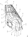
- FIGS 1 to 5 are schematic views of parts of the vehicle module 102 which comprises a single deck wagon body 103 for transporting passengers supported at both of its ends on a respective running gear 104 (e.g. a bogie) running on a track 105 defining a track level TOR (top of rail).
- a respective running gear 104 e.g. a bogie
- the wagon body 103 has a prismatic body section 103.1 (i.e. a body section having a substantially identical cross section in a plane perpendicular to the longitudinal direction at each point along the longitudinal direction) and a non-prismatic head section 103.2 defining an outer skin 103.4 of the wagon body 103.
- the transition (in some cases also forming a mechanical interface) between the prismatic body section 103.1 and the non-prismatic head section 103.2 starts in a plane 103.3 perpendicular to the longitudinal direction.
- the transition is not planar, i.e. certain lateral wall sections of the head section 103.2 continue the prismatic shape of the prismatic body section 103.1 beyond plane 103.3.
- this transition may have any other suitable shape and orientation in space.
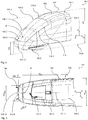
- the head section 103.2 is a comparatively slender, elongated and continuously tapering vehicle head section which has a head length HL of 5915 mm (i.e. a head length dimension in the longitudinal direction between the transition plane 103.3 and its foremost nose tip, see Figure 3 ) and a head height HH of 3870 mm (i.e. a head height dimension in the height direction between the rooftop at the transition plane 103.3 and the track level TOR, see Figure 2 ).
- a flow separation section 103.6 is formed in a nose section 103.5 of the head section 103.2.
- This flow separation section 103.6 comprises a flow separation device 103.7 in the form of a generally sickle shaped and generally concave depression 103.8 formed in the outer skin 103.4 of the wagon body 103 in the area of the nose section 103.5.
- the flow separation device 103.7 (at least at the nominal travelling speed of the vehicle 101) provides persistent separation of a first airflow 106.1 from the outer skin 103.4, the first airflow 106.1 forming the roof section part of the airflow 106 flowing along the outer skin 103.4.
- the flow separation device 103.7 comprises a sharp flow separation edge 103.9 extending, in the transverse direction (y-axis), over a major fraction of the nose section 103.5.
- the flow separation device 103.7 is arranged such that the flow separation edge 103.9 is a substantially planar structure defining a plane of main extension of the flow separation edge 103.9. It will be appreciated however that, with other embodiments of the invention, any other non-planar shape of the flow separation edge may be provided.
- the flow separation device 103.7 (in the height direction of the vehicle) is located in the lower half of the vehicle 101, in a fraction of the vehicle 101 that is limited to the still upward facing part of the lower 50% of the vehicle height dimension HH.
- the flow separation device 103.7 causes a well-defined and persistent separation of the airflow 106 from the outer skin 103.4 of the vehicle 101.
- the flow separation device 103.7 generates, at the flow separation edge 103.9, a change in the course of the outer skin 103.4 of the head section 103.2 that is sufficiently rapid, sharp and pronounced such that the upper fraction 106.1 of the airflow 106 (flowing along the roof area of the vehicle 101) cannot follow this change in the course of the outer skin 103.4 anymore and detaches in a defined manner from the outer skin 103.4.
- any statement made with respect to the flow along the outer skin 103.4 of the vehicle relates to the fraction of the boundary layer of the flow along the outer skin 103.4 which is decisive on the behavior of the flow, in particular on the fact if the flow detaches from the outer skin or not.
- the persistent detachment is achieved, among others, by the generally concave flow separation section 103.6 (also referred to as flow separation cavity 103.6 in the following) that is formed by the flow separation device 103.7 in the outer skin 103.4.
- the generally concave flow separation section 103.6 of the outer skin 103.4 imposes a change in the flow direction onto the passing upper flow fraction 106.1 which, when re-entering the generally convex part of the outer skin 103.3 of the nose section 103.5 downstream of the flow separation edge 103.9 leads to the result that the upper flow fraction 106.1 at this point experiences a rapid and pronounced change in the course of the outer skin 103.4 which it is unable to follow such that, ultimately, the flow detaches persistently from the outer skin 103.4.
- the flow separation cavity 103.6 is designed, in particular, is of sufficient size, to impose the desired change in direction on a sufficiently large part of the upper airflow fraction 106.1 to literally catapult the upper airflow fraction 106.1 away from the outer skin 103.4 at the flow separation edge 103.9.
- the flow separation device 103.7 more precisely the flow separation edge 103.9, in a transversally central area of the wagon body, in particular, in a central longitudinal plane 101.1, has a flow separation height HS above the track level TOR of 1370 mm, which corresponds to roughly 35% of the head height HH.
- the comparatively low and forward arrangement of the flow separation edge 103.9 close to the lower third of the vehicle module 102 and close to the nose tip 103.10 has several advantages.
- This effect typically referred to as pressure recovery effect, in a beneficial way reduces the overall aerodynamic drag of the vehicle 101. This particularly applies in comparison to the vehicles with early defined flow separation in the roof area, where this pressure recovery effect, due to the early detachment from the outer skin may only develop to a lesser extent.
- the persistent flow separation at the flow separation edge 103.9 generates a modification of the wake flow pattern that goes along with a modification of the static pressure distribution over the outer skin 103.4 of the trailing head section 103.2 that avoids a slipstream behaviour of a rail vehicle 107 (with a conventional high-speed train head design without a flow separation device according to the invention) as it is shown in Figure 6.
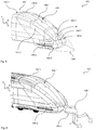
- Figure 6 illustrates a schematic perspective trailing head section 107.1 of such a conventional vehicle 107 and the formation of pronounced longitudinal wake vortices 108.1, 108.2 that were mentioned initially.
- each one of the longitudinal wake vortices shows a flow pattern which, in a central vertical plane of the track, has a strong flow speed component directed vertically downward (i.e. towards the track) and, down at track level, has a strong flow speed component directed laterally outward (as illustrated by the dashed arrows in Figure 6 ).
- the flow separation device 103.7 leads to a persistent flow separation in the associated lower fraction of the trailing end of the vehicle 101 (downstream of the flow separation device 103.7) which generates a rise in the static pressure in the airflow 106.1 passing the upper part or roof part of the outer skin 103.4.
- This persistent flow separation reduces the static pressure distribution and momentum differences with respect to the parts 106.2 of the airflow passing the lower lateral parts of the outer skin 103.4.
- this reduction in the variance of the static pressure distribution and in the momentum differences formation of the pronounced longitudinal wake vortices 108.1, 108.2 (otherwise typically dominating at such smoothly curved high-speed vehicle trailing ends as shown in Figure 6 ) is avoided.
- a flow separation pattern develops at the trailing end of the vehicle 101 which is completely different from the pronounced longitudinal wake vortices 108.1, 108.2 produced with conventional head section designs.
- This flow separation pattern is characterized by a relatively stable "wake bubble” (indicated in Figure 5 by the dot-dashed contour 109) dragged along with the vehicle 101.
- a relatively calm, micro-turbulent flow prevails.
- the outer surface of the wake bubble 109 substantially "continues" the outer skin 103.4 of the vehicle module 102 under a continuous reduction of the cross-section of the wake bubble 109 in a plane perpendicular to the longitudinal direction (x-axis).
- the wake bubble 109 has a shape that is substantially symmetric to the central longitudinal plane 101.1 (containing the x-axis and the z-axis). It will be appreciated that this wake bubble flow pattern provokes considerably less drag as well as considerably less aerodynamic trackside loads than the longitudinal wake vortices 108.1, 108.2 of conventional vehicle head designs.
- the static pressure distribution differences between the roof part 106.1 of the airflow 106 and the lateral parts 106.2 of the airflow 106 depend on the degree of so-called boat tailing of the head section 103.2 of the vehicle module 102.
- boat tailing hereby designates a design with a pronounced inward curvature of the lateral parts of the outer surface 103.4 towards the trailing end of the vehicle module 102. Consequently, the extension of the flow separation device 103.7 or the fraction of the part of the airflow 106 passing the flow separation device 103.7, respectively, may be the smaller the higher the degree of boat tailing is selected.
- the flow separation device 103.7 when located at the leading end of the vehicle, (if at all) only generates a comparatively moderate rise in the drag of the train 101.
- This moderate rise in the aerodynamic drag may be the result of a temporary separation of the flow (in this case coming from the free end of the nose section 103.5) from the outer skin 103.4.
- the flow separation at the leading end of the vehicle is not persistent, i.e. as long as the flow sufficiently rapidly re-attaches to the outer skin 103.4 in order to keep the increase in aerodynamic drag as low as possible.
- the placement of the flow separation device 103.7 in the lower half of the vehicle is particularly beneficial in this context, since such a detachment of the flow at a very early point close to the leading end of the vehicle 101 guarantees that the overall flow conditions provide a sufficiently high amount of energy to the locally detached flow promoting rapid reattachment to the outer skin 103.4. Hence, ultimately, when located at the leading end of the vehicle 101, at most only a comparatively small flow separation bubble forms in the area of the flow separation cavity 103.6.
- the flow separation device 103.7 more precisely, the flow separation edge 103.9 is pronouncedly spaced from a lower frame element of a front window 101.2 of the vehicle as well as the associated wiper 101.3. More precisely, the distance between the flow separation device 103.7 and the front window arrangement 101.2, 101.3 is more than half the distance (in the longitudinal direction) between these components and the nose tip 103.10. Hence, disturbances which may have been introduced into the flow 106.1 by these components will already have faded when reaching the flow separation device 103.7, in particular the flow separation edge 103.9, such that proper flow separation at the flow separation edge 103.9 is guaranteed.
- the flow separation device 103.7 comprises a first ramp section 103.11 and a second ramp section 103.12 of the outer skin 103.4, the flow separation edge 103.9 being formed at a conjunction of the first ramp section 103.11 and the second ramp section 103.12.
- the first ramp section 103.11 forms the flow separation cavity 103.6 and is located on the side of the flow separation edge 103.9 facing away from the nose tip 103.10 (i.e. located upstream of the flow separation edge 103.9 in case of operation at the trailing end of the vehicle 101).
- the second ramp section 103.12 descends from the flow separation edge 103.9 and is located on the side of the flow separation edge 103.9 facing towards the nose tip 103.10 (i.e. located downstream of the flow separation edge 103.9 in case of operation at the trailing end of the vehicle 101).
- the first ramp section 103.11 in the central longitudinal plane 101.1, has an inflection point IP at which the curvature of the outer skin 103.4 (in the central longitudinal plane 101.1) changes its sign in order to obtain the generally concave shape of the outer skin.
- the inflection point IP designates the start of the flow separation cavity 103.6.
- the inflection point IP is located an inflection point distance IPD (in the central longitudinal plane 101.1) from the flow separation edge 103.9.
- IPD in the central longitudinal plane 101.1
- the first ramp section 103.11 defines a first tangential direction T1 starting at the tangent starting point TSP, being tangent to the flow separation edge 103.9 and pointing towards nose tip 103.10.
- the first ramp section 103.11 is a substantially smooth and smoothly curved surface with substantially no (noticeable macroscopic) surface irregularities.
- the surface of the first ramp section 103.11 itself coincides with or forms a first median surface (as defined above) of the first ramp section 103.11.
- This median surface in the central longitudinal plane 101.1, at its transition to the flow separation edge 103.9, defines a second tangential direction T2 pointing towards the nose tip.
- the first tangential direction T1 substantially coincides with the first flow direction FS1 that is imposed on the upper airflow fraction 106.1 by the first ramp section 103.11 immediately when passing the flow separation edge 103.9 (at the nominal operating speed VN), along the outer skin in a direction parallel to the central longitudinal plane towards the free end.
- the difference between the first and third angle of inclination TA1, TA3 and the second angle of inclination TA2 varies as a function of the flow length of the first ramp section 103.11 along which the second angle of inclination TA2 prevails.
- the second ramp section 103.12 in a similar manner is a substantially smooth and smoothly curved surface with substantially no (noticeable macroscopic) surface irregularities.
- the surface of the second ramp section 103.12 itself coincides with or forms a second median surface (as defined above) of the second ramp section 103.12.
- the second median surface formed by surface of the second ramp section 103.12, in the central longitudinal plane 101.1, at its transition to the flow separation edge 103.9, defines a third tangential direction T4 pointing away from the free end of the head section, the third tangential direction T4, in a sector facing in the height direction, being inclined with respect to the first tangential direction T1 by an angle of inclination of 134°.
- the second ramp section 103.1 in the central longitudinal plane 101.1, at the flow separation edge 103.9, imposes a second flow direction FS2 onto a second airflow flowing, at the nominal operating speed, along the outer skin 103.4 in a direction parallel to the central longitudinal plane 101.1 away from the free end of the head section (as it is the case during operation at the leading end of the vehicle 101).
- the second flow direction FS2 coincides with the third tangential direction T4.
- the flow separation device 103.7 is substantially symmetric with respect to the central longitudinal plane 101.1.
- the flow separation edge 103.9 in one single edge section, extends over the entire flow separation step 103.7 (i.e. from one lateral surface to the opposing lateral surface of the vehicle module 102) and is designed as a sharp, pronounced edge, thereby achieving in a simple manner the desired flow separation pattern with an aerodynamically advantageous shape of the wake bubble 109.
- the flow separation edge with other embodiments of the invention, may also be provided in a plurality of spatially distinct edge sections.
- the flow separation edge 103.9 Over its entire length (i.e. over the entire edge section), the flow separation edge 103.9 defines a tangential direction (in each point of the edge section).
- the flow separation edge 103.9 in a sectional plane perpendicular to this tangential direction, has a radius of curvature of 5 mm guaranteeing persistent flow separation in a simple and efficient manner.
- a flow separation step is formed by the first ramp section 103.11 and the second ramp section 103.12 which, on the one hand, provokes (at the trailing end of the vehicle 101) a flow that has a first flow direction FS1 at the flow separation edge 103.9 and which, on the other hand, has the second ramp section 103.12 located (in this first flow direction FS1) downstream of the flow separation edge 103.9 and sharply folds away with respect to this first flow direction FS1 by 40° such that the transverse distance (i.e. the distance in a direction transverse to the first flow direction FS1) between the separated flow 106.1 and the second ramp section 103.12 quickly increases as the flow 106.1 propagates.
- the second ramp section 103.12 does not necessarily have to be smoothly curved wall element. Rather, it may be a straight wall element as well as be arbitrarily curved (in one or two directions) or may be an (arbitrary) combination of curved and/or straight sections.
- an aerodynamically particularly beneficial configuration is achieved in that the flow separation edge 103.9, from one lateral surface to the other lateral surface of the wagon body 102, substantially seamlessly continues crosswind flow separation edges 110.1 of two crosswind flow separation devices 110 laterally extending in the longitudinal direction along the upper side of the head section 103.2 alongside the front window 101.2 as they are known from EP 2 383 161 A1 (the entire disclosure of which is Incorporated herein by reference).
- flow separation edges 110.1 and 103.9 together form a generally U-shaped flow separation edge substantially framing the upward facing part of the outer skin 103.4 of the head section 103.2.
- the flow separation edge 103.9 in a perpendicular projection onto a transverse plane perpendicular to the longitudinal direction, has a maximum effective edge width Ws max in the transverse direction (y-axis) which is defined by the points where a tangent to the flow separation edge 103.9 in a plane perpendicular to the height direction reaches inclination of 45° with respect to the transverse direction as it is shown in Figure 3 .
- a size of the flow separation cavity 103.6 is obtained, which generates an impact on the airflow 106.1 that is sufficiently large to catapult it away from the outer skin 103.4.
- the flow separation device 103.7 despite being a passive component as outlined above, is deactivated when located at the leading end of the vehicle 101 by simply covering the flow separation cavity 103.6 with a suitable cover as it is indicated by the dashed contour 111 in Figure 4 .
- the flow separation device 103.7 preferably comprises an interface unit (not shown) configured to mount the cover device 111 in a deactivated state of the flow separation device 103.7.
- such a cover 111 is shaped such that it substantially continues the smooth surface of the surrounding outer skin 103.4 of the wagon body 102, thereby potentially avoiding any rise in the aerodynamic drag at the leading end of the vehicle 101 due to the flow separation device 103.7.
- the only difference of the vehicle 201 with respect to the vehicle 101 lies in the specific design parameters of the flow separation device 203.7 of the nose section 203.5 of the vehicle module 202 which, apart from the nose section 203.5 shown in Figure 7 , is identical to the vehicle module 102.
- the flow separation device 203.7 more precisely the flow separation edge 203.9, in a transversally central area of the wagon body, in particular, in the central longitudinal plane 101.1, has a flow separation height HS above the track level TOR of 1386 mm, which again corresponds to roughly 36% of the head height HH.
- the third angle of inclination TA3 is equal to the first angle of inclination TA1.
- the only difference of the vehicle 301 with respect to the vehicle 101 also lies in the specific design parameters of the flow separation device 303.7 of the nose section 303.5 of the vehicle module 302 which, apart from the nose section 303.5 shown in Figure 8 , is identical to the vehicle module 102.
- the flow separation device 303.7 more precisely the flow separation edge 303.9, in a transversally central area of the wagon body, in particular, in the central longitudinal plane 101.1, has a flow separation height HS above the track level TOR of 1334 mm, which again corresponds to roughly 35% of the head height HH.
- the third angle of inclination TA3 is equal to the first angle of inclination TA1.
- the only difference of the vehicle 401 with respect to the vehicle 101 also lies in the specific design parameters of the flow separation device 403.7 of the nose section 403.5 of the vehicle module 402 which, apart from the nose section 403.5 shown in Figure 9 , is identical to the vehicle module 102.
- the flow separation device 403.7 more precisely the flow separation edge 403.9, in a transversally central area of the wagon body, in particular, in the central longitudinal plane 101.1, has a flow separation height HS above the track level TOR of 1475 mm, which corresponds to roughly 38% of the head height HH.
- the third angle of inclination TA3 is equal to the first angle of inclination TA1.
- the only difference of the vehicle 501 with respect to the vehicle 101 also lies in the specific design parameters of the flow separation device 503.7 of the nose section 503.5 of the vehicle module 502 which, apart from the nose section 503.5 shown in Figure 10 , is identical to the vehicle module 102.
- the flow separation device 503.7 more precisely the flow separation edge 503.9, in a transversally central area of the wagon body, in particular, in the central longitudinal plane 101.1, has a flow separation height HS above the track level TOR of 1386 mm, which corresponds to roughly 36% of the head height HH.
- the third angle of inclination TA3 is equal to the first angle of inclination TA1.
- any of the nose sections 203.5 to 503.5 simply replace the nose section 103.5 of the vehicle 101 to form the respective vehicle 201 to 501.
- vehicle 601 in its basic design and functionality, largely corresponds to the vehicle 101 such that it will be mainly referred to the differences only. Moreover, identical or like components are given the same reference numerals increased by 500. Unless deviating explanations are given in the following it is here explicitly referred to the explanations given above with respect to the features and functions of these components.
- the only difference of the vehicle 601 with respect to the vehicle 101 lies in the specific design of the flow separation device 603.7 of the nose section 603.5 of the vehicle module 602 which, apart from the nose section 603.5 shown in Figure 11 and 12 , is identical to the vehicle module 102.
- the nose section 603.5 simply replaces the nose section 103.5 of the vehicle 101.
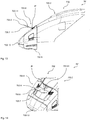
- the flow separation device 603.7 is a selectively activatable device in the form of a retractable, generally plate shaped element, which forms the flow separation edge 603.9 at its free end facing away from the outer skin 103.4.
- the flow separation device 603.7 in its deactivated state (not shown) is fully retracted behind the outer skin 103.4 in the longitudinal direction, such that the flow separation edge 603.9 is fully flush with the surrounding outer skin 103.4.
- the fully retracted and, hence, aerodynamically deactivated flow separation device 603.7 does not cause any drag.
- the inflection point IP is formed at the intersection between the plate shaped flow separation device 603.7 and the outer skin, such that here as well a generally concave flow separation flow separation section 603.6 is formed, which provides the necessary change in the direction of the airflow fraction 106.1 necessary to persistently detach from the outer skin 104.3 and provide the desired wake flow pattern as described in the context of the first embodiment (in particular in the context of Figure 5 ).
- the flow separation device 603.7 forms a first ramp section 603.11 upstream of the flow separation edge 603.9 which provides the desired change in the direction of the airflow fraction 106.1. Due to the fact that the flow separation device 603.7 is a simple generally plate shaped element, the airflow fraction 106.1 after passing the flow separation edge 603.9 persistently detaches from the outer skin 104.3 as long as there is a sufficient distance between the free end of the plate 603.7 with the flow separation edge 603.9 and the adjacent part of the outer skin.
- the flow separation device 603.7 more precisely the flow separation edge 603.9, in a transversally central area of the wagon body, in particular, in the central longitudinal plane 101.1, has a flow separation height HS above the track level TOR of 1768 mm, which corresponds to roughly 46% of the head height HH.
- the third angle of inclination TA3 is equal to the first angle of inclination TA1.
- the flow separation device 606.7 may be used are set to different extensions from the outer skin 103.4 and/or to different angles of inclination with respect to the outer skin 103.4. In the following corresponding examples will be given.
- the third angle of inclination TA3 is equal to the first angle of inclination TA1.
- Ws max 800 mm (i.e. 28% of the maximum wagon body width W max ).
- an overall reduction between 2% and 2.5% in the aerodynamic drag of the train 601 may also be achieved.
- the third angle of inclination TA3 is equal to the first angle of inclination TA1.
- Ws max 800 mm (i.e. 28% of the maximum wagon body width W max ).
- the third angle of inclination TA3 is equal to the first angle of inclination TA1.
- Ws max 800 mm (i.e. 28% of the maximum wagon body width W max ).
- the third angle of inclination TA3 is equal to the first angle of inclination TA1.
- Ws max 800 mm (i.e. 28% of the maximum wagon body width W max ).
- an overall reduction between 1.5% and 2.0% in the aerodynamic drag of the train 601 may be achieved here as well.
- vehicle 701 in its basic design and functionality, largely corresponds to the vehicle 101 such that it will be mainly referred to the differences only. Moreover, identical or like components are given the same reference numerals increased by 600. Unless deviating explanations are given in the following it is here explicitly referred to the explanations given above with respect to the features and functions of these components.
- the only difference of the vehicle 701 with respect to the vehicle 101 lies in the specific design of the flow separation device 703.7 of the nose section 703.5 of the vehicle module 702 which, apart from the nose section 703.5 shown in Figure 13 and 14 , is identical to the vehicle module 102.
- the nose section 703.5 simply replaces the nose section 103.5 of the vehicle 101.
- the flow separation device 703.7 is a selectively activatable device in the form of a pivotable, generally plate shaped element, which forms the flow separation edge 703.9 at its free end facing away from the outer skin 103.4.
- the flow separation device 703.7 in its deactivated state (not shown) is pivoted about a pivot axis extending in the transverse direction, such that the upper surface of the flow separation device 703.7 is fully flush with the surrounding outer skin 103.4.
- the head section 703.2 forms the leading end of the vehicle 701
- aerodynamically deactivated flow separation device 703.7 does not cause any drag.
- the inflection point IP is formed at the intersection between the plate shaped flow separation device 703.7 and the outer skin, such that here as well a generally concave flow separation flow separation section 703.6 is formed, which provides the necessary change in the direction of the airflow fraction 106.1 necessary to persistently detach from the outer skin 104.3 and provide the desired wake flow pattern as described in the context of the first embodiment (in particular in the context of Figure 5 ).
- the flow separation device 703.7 forms a first ramp section 703.11 upstream of the flow separation edge 703.9 which provides the desired change in the direction of the airflow fraction 106.1. Due to the fact that the flow separation device 703.7 is a simple generally plate shaped element, the airflow fraction 106.1 after passing the flow separation edge 703.9 persistently detaches from the outer skin 104.3 as long as there is a sufficient distance between the free end of the plate 703.7 with the flow separation edge 703.9 and the adjacent part of the outer skin.
- the flow separation device 703.7 more precisely the inflection point IP, in a transversally central area of the wagon body, in particular, in the central longitudinal plane 101.1, has a height above the track level TOR of 2235 mm which corresponds to roughly 57% of the head height HH.
- the flow separation edge 703.9 has a height above the track level TOR of 2475 mm, which corresponds to roughly 63% of the head height HH. Nevertheless, the decisive point of the onset of the flow separation device 703.7 formed by the inflection point IP still is below 60% of the head height HH.
- the third angle of inclination TA3 is equal to the first angle of inclination TA1.
Landscapes
- Engineering & Computer Science (AREA)
- Mechanical Engineering (AREA)
- Body Structure For Vehicles (AREA)
Claims (15)
- Fahrzeug, insbesondere Schienenfahrzeug, für einen bidirektionalen Betrieb bei einer Nennfahrgeschwindigkeit, insbesondere über 160 km/h bis 200 km/h, in einer jeweiligen Fahrtrichtung, umfassend- wenigstens ein Fahrzeugmodul (102; 202 ; 302; 402) mit einem Wagenkasten (103; 203; 303; 403), der auf einem Fahrwerk (104) abgestützt ist ist, das dazu ausgebildet ist auf einem ein Gleisniveau definierenden Gleis (105) zu fahren, wobei- das Fahrzeugmodul (102; 202; 302; 402) eine Längsrichtung, eine Querrichtung und eine Höhenrichtung definiert;- der Wagenkasten (103; 203; 303; 403) eine Außenhaut (103.4; 203.4; 303.4; 403.4) aufweist, die einen generell prismatischen Körperabschnitt und einen nichtprismatischen, sich lateral verjüngenden Kopfabschnitt (103.2; 203.2; 303.2; 403.2) definiert, der sich an einem seiner Enden befindet;- das Fahrzeugmodul (102; 202; 302; 402) an einem Übergang zwischen dem Körperabschnitt und dem Kopfabschnitt eine maximale Fahrzeughöhenabmessung über der Gleisebene in der Höhenrichtung aufweist;- der Wagenkasten (103; 203; 303; 403), in einem nach oben weisenden Teil des Kopfabschnitts, einen Strömungsabrissabschnitt (103.6; 203.6; 303.6; 403.6) aufweist, der eine Strömungsabrissvorrichtung (103.7; 203.7; 303.7; 403.7), insbesondere eine Strömungsabrisskante (103.9; 203.9; 303.9; 403.9), aufweist;- die Strömungsabrissvorrichtung (103.7; 203.7; 303.7; 403.7), insbesondere die Strömungsabrisskante, in einem in Querrichtung zentralen Bereich des Wagenkastens (103; 203; 303; 403) und wenigstens in einem aktivierten Zustand, in einer Strömungsabrisshöhe in Fahrzeughöhenrichtung angeordnet ist;- die Strömungsabrissvorrichtung (103.7; 203.7; 303.7; 403.7) eine dauerhafte Ablösung eines oberen Anteils eines Luftstroms (106) von der Außenhaut (103.4; 203.4; 303.4; 403.4) des Wagenkastens (103; 203; 303; 403) bereitstellt, wenn das Fahrzeugmodul (102; 202; 302; 402) mit der Fahrgeschwindigkeit fährt, wobei der Kopfabschnitt (103.2; 203.2; 303.2; 403.2) ein hinteres Ende des Fahrzeugmoduls (102; 202; 302; 402) bildet;
dadurch gekennzeichnet, dass- die Strömungsabrissvorrichtung (103.7; 203.7; 303.7; 403.7), wenigstens in dem aktivierten Zustand, einen im Wesentlichen konkaven Strömungsabrissabschnitt der Außenhaut definiert,- die Strömungsabrisshöhe bis zu 50% bis 65% der maximalen Fahrzeughöhenabmessung, vorzugsweise von 25% bis 50% der maximalen Fahrzeughöhenabmessung, weiter vorzugsweise von 30% bis 46% der maximalen Fahrzeughöhenabmessung, weiter vorzugsweise von 33% bis 39% der maximalen Fahrzeughöhenabmessung, reicht. - Fahrzeug nach Anspruch 1, wobei- die Strömungsabrisshöhe bis zu 2500 mm, vorzugsweise von 900 mm bis 1850 mm, weiter vorzugsweise von 1150 mm bis 1650 mm, weiter vorzugsweise von 1275 mm bis 1750 mm, reicht, wobei die Strömungsabrissvorrichtung insbesondere eine permanent wirksame passive Vorrichtung ist, und die Strömungsabrisshöhe von 1100 mm bis 1700 mm, vorzugsweise von 1200 mm bis 1500 mm, weiter vorzugsweise von 1300 mm bis 1400 mm reicht, oder die Strömungsabrissvorrichtung insbesondere eine selektiv aktivierbare Vorrichtung ist, insbesondere eine generell plattenförmige Vorrichtung ist, und die Strömungsabrisshöhe von 900 mm bis 2500 mm, vorzugsweise von 1300 mm bis 1900 mm, weiter vorzugsweise von 1600 mm bis 1750 mm reicht;
und/oder- die Strömungsabrissvorrichtung, insbesondere die Strömungsabrisskante, in einer zentralen, zur Querrichtung senkrechten Längsebene einen Nasenabstand in Längsrichtung von einem freien Ende des Kopfabschnitts aufweist, und der Kopfabschnitt eine maximale Länge in der Längsrichtung aufweist;- wobei der Nasenabstand von 0 mm bis 600 mm, vorzugsweise von 30 mm bis 350 mm, weiter vorzugsweise von 50 mm bis 200 mm, reicht, wobei die Strömungsabrissvorrichtung insbesondere eine permanent wirksame passive Vorrichtung ist, und der Nasenabstand von 0 mm bis 400 mm, vorzugsweise von 90 mm bis 200 mm, weiter vorzugsweise von 90 mm bis 150 mm, reicht, oder die Strömungsabrissvorrichtung insbesondere eine selektiv aktivierbare Vorrichtung ist, insbesondere eine generell plattenförmige Vorrichtung ist, und der Nasenabstand von 0 mm bis 600 mm, vorzugsweise von 20 mm bis 350 mm, weiter vorzugsweise von 40 mm bis 200 mm, reicht;
und/oder- der Nasenabstand von 0% bis 11%, vorzugsweise von 0% bis 6%, weiter vorzugsweise von 1,0% bis 3,5%, der maximalen Länge reicht, wobei die Strömungsabrissvorrichtung insbesondere eine permanent wirksame passive Vorrichtung ist und der Nasenabstand von 0% bis 7%, vorzugsweise von 1% bis 4,5%, weiter vorzugsweise von 1,5% bis 3,5%, der maximalen Länge reicht, oder wobei die Strömungsabrissvorrichtung insbesondere eine selektiv aktivierbare Vorrichtung ist, insbesondere eine generell plattenförmige Vorrichtung ist, und der Nasenabstand von 0% bis 12%, vorzugsweise von 0% bis 6%, weiter vorzugsweise von 0,5% bis 3,5%, der maximalen Länge reicht. - Fahrzeug nach Anspruch 1 oder 2, wobei- ein Vorlaufteil der Außenhaut, der auf einer Seite der Strömungsabrissvorrichtung angeordnet ist, die von einem freien Ende des Kopfabschnitts abgewandt ist, in einer zentralen, zur Querrichtung senkrechten Längsebene eine Vorlaufströmungsrichtung auf den Luftstrom aufbringt, die gegenüber der Längsrichtung um 20° bis 60°, vorzugsweise um 30° bis 50°, weiter vorzugsweise um 35° bis 45°, geneigt ist; und- die Strömungsabrissvorrichtung (103.7; 203.7; 303.7; 403.7), wenigstens in dem aktivierten Zustand, einen ersten Rampenabschnitt aufweist, der benachbart zu der Strömungsabrisskante (103.9; 203.9; 303.9; 403.9) auf einer Seite der Strömungsabrisskante angeordnet ist, die von einem freien Ende des Kopfabschnitts abgewandt ist,
wobei- der erste Rampenabschnitt, in einer zentralen, zur Querrichtung senkrechten Längsebene , einen Tangentenstartpunkt an der Außenhaut aufweist, der sich in einem Abstand von 150 mm von der Strömungsabrisskante befindet und eine erste Tangentenrichtung definiert, die an dem Tangentenstartpunkt beginnt, die tangential zu der Strömungsabrisskante verläuft und in Richtung eines freien Endes des Kopfabschnitts zeigt, wobei die erste Tangentenrichtung in Bezug auf die Längsrichtung um einen ersten Neigungswinkel geneigt ist, wobei der erste Neigungswinkel von -25° bis +25°, vorzugsweise von -15° bis +20°, weiter vorzugsweise von 0° bis +15°, reicht, wobei ein positiver Wert des ersten Neigungswinkels dafür repräsentativ ist, dass die erste tangentiale Richtung eine Komponente in Richtung des Gleises aufweist;
und/oder wobei- die Außenhaut eine erste Medianfläche des ersten Rampenabschnitts definiert und die erste Medianfläche in einer zentralen, zur Querrichtung senkrechten Längsebene an ihrem Übergang zu der Strömungsabrisskante eine zweite Tangentenrichtung definiert, die in Richtung eines freien Endes des Kopfabschnitts zeigt, wobei die zweite Tangentenrichtung in Bezug auf die Längsrichtung um einen zweiten Neigungswinkel geneigt ist, wobei der zweite Neigungswinkel von -25° bis +25°, vorzugsweise von -10° bis +15°, weiter vorzugsweise von -5° bis +10°, reicht, wobei ein positiver Wert des zweiten Neigungswinkels dafür repräsentativ ist, dass die zweite tangentiale Richtung eine Komponente in Richtung des Gleises aufweist;
und/oder wobei- der erste Rampenabschnitt in einer zentralen, zur Querrichtung senkrechten Längsebene dazu ausgebildet ist, an der Strömungsabrisskante einem ersten Luftstrom, der bei der Nennfahrgeschwindigkeit entlang der Außenhaut in einer Richtung parallel zu der zentralen Längsebene in Richtung des freien Endes strömt, eine erste Strömungsrichtung aufzuprägen, wobei die erste Strömungsrichtung in Bezug auf die Längsrichtung um einen dritten Neigungswinkel geneigt ist, wobei der dritte Neigungswinkel von -25° bis +25°, vorzugsweise von -15° bis +20°, weiter vorzugsweise von 0° bis +15°, reicht, wobei ein positiver Wert des dritten Neigungswinkels dafür repräsentativ, dass der erste Luftstrom eine Strömungskomponente in Richtung des Gleises aufweist. - Fahrzeug nach Anspruch 3, wobei- die Strömungsabrissvorrichtung eine permanent wirksame passive Vorrichtung ist, wobei der erste Neigungswinkel und/oder der dritte Neigungswinkel von -5° bis +25°, vorzugsweise von 0° bis +20°, weiter vorzugsweise von +1° bis +15°, reicht, und/oder der zweite Neigungswinkel von -5° bis +15°, vorzugsweise von 0° bis +10°, weiter vorzugsweise von +1° bis +5°, reicht;
oder- die Strömungsabrissvorrichtung eine selektiv aktivierbare Vorrichtung ist, insbesondere eine generell plattenförmige Vorrichtung ist, wobei der erste Neigungswinkel und/oder der zweite Neigungswinkel und/oder der dritte Neigungswinkel von -30° bis +20°, vorzugsweise von -20° bis +15°, weiter vorzugsweise von -10° bis + 10°, reicht. - Fahrzeug nach Anspruch 3 oder 4, wobei- die Strömungsabrissvorrichtung (103.7; 203.7; 303.7; 403.7) einen zweiten Rampenabschnitt aufweist, der benachbart zu der Strömungsabrisskante auf einer Seite der Strömungsabrisskante angeordnet ist, die zu dem freien Ende des Kopfabschnitts weist;
wobei- die Außenhaut eine zweite Medianfläche des zweiten Rampenabschnitts definiert und die zweite Medianfläche in der zentralen Längsebene, an ihrem Übergang zu der Strömungsabrisskante eine dritte Tangentenrichtung definiert, die von dem freien Ende des Kopfabschnitts wegzeigt, wobei die dritte Tangentenrichtung in einem Sektor, der in die Höhenrichtung weist, in Bezug auf die erste tangentiale Richtung um 60° bis 160°, vorzugsweise um 90° bis 150°, weiter vorzugsweise um 110° bis 140°, geneigt ist;
und/oder wobei- der zweite Rampenabschnitt, in der zentralen Längsebene, dazu ausgebildet ist, an der Strömungsabrisskante einem zweiten Luftstrom, der bei der Nennbetriebsgeschwindigkeit entlang der Außenhaut parallel zu der zentralen Längsebene in einer Richtung von dem freien Ende des Kopfabschnitts her strömt, eine zweite Luftströmungsrichtung aufzuprägen, wobei die zweite Strömungsrichtung in einem in die Höhenrichtung weisenden Sektor gegenüber der ersten Strömungsrichtung um 60° bis 160°, vorzugsweise um 90° bis 150°, weiter vorzugsweise um 110° bis 140°, geneigt ist. - Fahrzeug nach einem der vorhergehenden Ansprüche, wobei- der Strömungsabrissabschnitt in einer zentralen, zur Querrichtung senkrechten Längsebene einen Wendepunkt aufweist, an dem insbesondere eine Krümmung der Außenhaut ihr Vorzeichen ändert und/oder ein Knick in der Außenhaut gebildet ist;- der Wendepunkt in der zentralen Längsebene einen Wendepunktabstand von der Strömungsabrisskante aufweist, und- der Kopfabschnitt eine maximale Kopflänge in der Längsrichtung aufweist; wobei- der Wendepunktabstand von 50 mm bis 900 mm, vorzugsweise von 150 mm bis 800 mm, weiter vorzugsweise von 150 mm bis 500 mm, reicht;- die Strömungsabrissvorrichtung insbesondere eine permanent wirksame passive Vorrichtung ist, und der Wendepunktabstand von 50 mm bis 700 mm, vorzugsweise von 120 mm bis 600 mm, weiter vorzugsweise von 150 mm bis 500 mm, reicht; oder die Strömungsabrissvorrichtung insbesondere eine selektiv aktivierbare Vorrichtung ist, insbesondere eine generell plattenförmige Vorrichtung ist, und der Wendepunktabstand von 50 mm bis 900 mm, vorzugsweise von 250 mm bis 800 mm, weiter vorzugsweise von 300 mm bis 600 mm, reicht;
und/oder wobei- der Wendepunktabstand im Bereich von 0,7% bis 15%, vorzugsweise von 2,5% bis 13,5%, weiter vorzugsweise von 2,5% bis 8,5% , der maximalen Kopflänge reicht;- die Strömungsabrissvorrichtung insbesondere eine permanent wirksame passive Vorrichtung ist und der Wendepunktabstand von 0,7% bis 12%, vorzugsweise von 2% bis 10%, weiter vorzugsweise von 2,5% bis 8,5%, der maximalen Kopflänge reicht, oder die Strömungsabrissvorrichtung insbesondere eine selektiv aktivierbare Vorrichtung ist, insbesondere eine generell plattenförmige Vorrichtung ist, und der Wendepunktabstand von 0,5% bis 15%, vorzugsweise von 4% bis 13,5%, weiter vorzugsweise von 5% bis 10%, der maximalen Kopflänge reicht. - Fahrzeug nach einem der vorhergehenden Ansprüche, wobei- die Strömungsabrissvorrichtung (103.7; 203.7; 303.7; 403.7) eine scharfe Strömungsabrisskante (103.9; 203.9; 303.9; 403.9) aufweist;- die Strömungsabrisskante (103.9; 203.9; 303.9; 403.9) wenigstens einen Kantenabschnitt aufweist, der in jedem Punkt des Kantenabschnitts eine tangentiale Richtung definiert;- die Strömungsabrisskante (103.9; 203.9; 303.9; 403.9), in dem Kantenabschnitt und in einer Schnittebene senkrecht zu der tangentialen Richtung, einen Krümmungsradius von weniger als 15 mm, vorzugsweise von weniger als 10 mm, weiter vorzugsweise von weniger als 5 mm, aufweist;- sich der Kantenabschnitt, insbesondere über wenigstens 60% der Strömungsabrisskante (103.9; 203.9; 303.9; 403.9), vorzugsweise über wenigstens 80% der Strömungsabrisskante (103.9; 203.9; 303.9; 403.9), weiter vorzugsweise über im Wesentlichen 100% der Strömungsabrisskante (103,9; 203,9; 303,9; 403,9), erstreckt.
- Fahrzeug nach einem der vorhergehenden Ansprüche, wobei- sich die Strömungsabrisskante (103.7; 203.7; 303.7; 403.7), insbesondere kontinuierlich, von einer Seitenfläche zu einer gegenüberliegenden Seitenfläche des Wagenkastens (103; 203; 303; 403) erstreckt,- die Strömungsabrisskante insbesondere wenigstens eine Seitenwindströmungsabrisskante, insbesondere im Wesentlichen nahtlos, fortsetzt, wobei sich die wenigstens eine Seitenwindströmungsabrisskante in Längsrichtung entlang wenigstens einer der Seitenflächen des Wagenkastens erstreckt;- sich die wenigstens eine Seitenwindströmungsabrisskante in der Längsrichtung entlang einer Frontscheibe des Fahrzeugs, insbesondere bis zu einem Dachabschnitt des Wagenkastens, erstreckt;- die Strömungsabrissvorrichtung (103.7; 203.7; 303.7; 403.7) insbesondere in Bezug auf eine zur Querrichtung senkrechte zentrale Längsebene im Wesentlichen symmetrisch ist.
- Fahrzeug nach einem der vorhergehenden Ansprüche, wobei- eine senkrechte Projektion der Strömungsabrisskante (103.9; 203.9; 303.9; 403.9) auf eine transversale Ebene, die senkrecht zu der Längsrichtung verläuft, eine maximale Kantenbreite Wsmax in der Querrichtung aufweist, die von 500 mm bis 2500 mm, vorzugsweise von 700 mm bis 1900 mm, weiter vorzugsweise von 800 mm bis 1850 mm, reicht; wobei die Strömungsabrissvorrichtung insbesondere eine permanent wirksame passive Vorrichtung ist und die maximale Kantenbreite Wsmax von 500 mm bis 2500 mm, vorzugsweise von 1200 mm bis 1900 mm, weiter vorzugsweise von 1300 mm bis 1850 mm, reicht; oder die Strömungsabrissvorrichtung insbesondere eine selektiv aktivierbare Vorrichtung ist, insbesondere eine generell plattenförmige Vorrichtung ist, und die maximale Kantenbreite Wsmax von 500 mm bis 1100 mm, vorzugsweise von 700 mm bis 1000 mm, weiter vorzugsweise von 750 mm bis 900 mm, reicht;
und/oder- eine senkrechte Projektion der Strömungsabrisskante (103.9; 203.9; 303.9; 403.9) auf eine transversale Ebene, die senkrecht zu der Längsrichtung verläuft, eine maximale Kantenbreite Wsmax in der Querrichtung aufweist und die Außenhaut (103.4; 203.4; 303.4; 403.4) in der Querrichtung eine maximale Wagenkastenbreite Wmax aufweist, wobei die maximale Kantenbreite Wsmax von 15% bis 70%, vorzugsweise von 25% bis 65%, weiter vorzugsweise von 45% bis 65%, der maximalen Wagenkastenbreite Wmax reicht, wobei die Strömungsabrissvorrichtung insbesondere eine permanent wirksame passive Vorrichtung ist und die maximale Kantenbreite Wsmax von 15% bis 70%, vorzugsweise von 40% bis 65%, weiter vorzugsweise von 45% bis 60%, der maximalen Wagenkastenbreite Wmax reicht, oder die Strömungsabrissvorrichtung, insbesondere eine selektiv aktivierbare Vorrichtung ist, insbesondere eine generell plattenförmige Vorrichtung ist, und die maximale Kantenbreite Wsmax von 15% bis 40%, vorzugsweise von 25% bis 35%, weiter vorzugsweise von 27% bis 32%, der maximalen Wagenkastenbreite Wmax reicht. - Fahrzeug nach einem der vorhergehenden Ansprüche, wobei- die Strömungsabrisskante (103.9; 203.9; 303.9; 403.9) wenigstens zum Teil durch eine permanent aerodynamisch aktive Komponente der Strömungsabrissvorrichtung (103.7; 203.7; 303.7; 403,7) gebildet ist;
und/oder- die Strömungsabrisskante wenigstens teilweise von einem im Wesentlichen starren Teil der Außenhaut gebildet wird;
und/oder- die Strömungsabrissvorrichtung wenigstens teilweise durch eine Vertiefung in der Außenhaut gebildet wird, wobei die Vertiefung insbesondere im Wesentlichen sichelförmig ist;
und/oder- die Strömungsabrissvorrichtung eine Schnittstelleneinheit umfasst, die dazu ausgebildet ist eine Abdeckvorrichtung zu montieren, die dazu ausgebildet ist, um die Strömungsabrissvorrichtung in einem deaktivierten Zustand abzudecken. - Fahrzeug nach einem der vorhergehenden Ansprüche, wobei- die Strömungsabrissvorrichtung eine selektiv aktivierbare Komponente ist, die in ihrem aktivierten Zustand aerodynamisch wirksam ist;- die Strömungsabrissvorrichtung insbesondere eine schwenkbare Klappeneinheit umfasst, wobei die schwenkbare Klappeneinheit einen aktivierten Zustand und einen deaktivierten Zustand aufweist, wobei die schwenkbare Klappeneinheit in dem deaktivierten Zustand einen Teil der Außenhaut bildet, der mit benachbarten Teilen im Wesentlichen bündig ist, und die schwenkbare Klappeneinheit in dem aktivierten Zustand, von der Außenhaut vorsteht, um an einem freien Ende eine Strömungsabrisskante der Strömungsabrissvorrichtung zu bilden;
und/oder- die Strömungsabrissvorrichtung insbesondere eine einziehbare Einheit umfasst, wobei die einziehbare Einheit einen aktivierten Zustand und einen deaktivierten Zustand aufweist, wobei die einziehbare Einheit in dem deaktivierten Zustand in die Außenhaut eingezogen ist, insbesondere im Wesentlichen vollständig in die Außenhaut eingezogen ist, sodass eine im Wesentlichen bündige Außenhaut in einem Bereich der deaktivierten Strömungsabrissvorrichtung gebildet wird, und die einziehbare Einheit in dem aktivierten Zustand von der Außenhaut vorsteht, um an einem freien Ende eine Strömungsabrisskante der Strömungsabrissvorrichtung zu bilden, wobei die einziehbare Einheit insbesondere ein im Wesentlichen plattenförmiges Strömungsabrisselement aufweist; wobei das Strömungsabrisselement insbesondere eine wenigstens abschnittsweise ebene und/oder wenigstens abschnittsweise gekrümmte Strömungsleitfläche bildet. - Fahrzeug nach einem der vorhergehenden Ansprüche, wobei- die Strömungsabrissvorrichtung (103.7; 203.7; 303.7; 403.7) derart angeordnet ist, dass sich die dauerhafte Trennung eines ersten Luftstroms (106.1) von der Außenhaut (103.4; 203.4; 303.4; 403.4) des Wagenkastens (103.8; 203.8; 303.8; 403.8) über einen Strömungsabrissbereich der Außenhaut (103.4; 203.4; 303.4; 403.4) erstreckt;- der Strömungsabrissbereich ausreichend groß ist, um einen ersten Anstieg einer statischen Druckverteilung innerhalb des abgelösten ersten Luftstroms (106.1) zu erzeugen und um die Bildung zweier ausgeprägter longitudinaler Wirbelschleppen in einem Nachlauf des Wagenkastens (103; 203; 303; 403) zu verringern, insbesondere im Wesentlichen zu vermeiden;- wobei der erste Anstieg der statischen Druckverteilung innerhalb des abgelösten Luftstroms (106.1) insbesondere als Funktion in Abhängigkeit von einer statischen Druckverteilung in einem benachbarten seitlichen zweiten Luftstrom (106.2) über einen seitlichen Teil der Außenhaut (103.4; 203.4; 303.4; 403.4) des Wagenkastens (103; 203; 303; 403) gewählt ist, der zu der Strömungsabrissvorrichtung (103.7; 203.7; 303.7; 403.7) benachbart ist;
- Fahrzeug nach einem der vorhergehenden Ansprüche, wobei- die Strömungsabrissvorrichtung (103.7; 203.7; 303.7; 403.7) eine erste Strömungsabrissvorrichtung ist, die an einem ersten Ende des Fahrzeugs angeordnet ist;- eine zweite Strömungsabrissvorrichtung an einem gegenüberliegenden zweiten Ende des Fahrzeugs angeordnet ist,- das Fahrzeug insbesondere mehrere separate Fahrzeugmodule umfasst, die gelenkig miteinander verbunden sind, wobei die erste Strömungsabrissvorrichtung an einem ersten Fahrzeugmodul angeordnet ist und die zweite Strömungsabrissvorrichtung an einem gegenüberliegenden zweiten Fahrzeugmodul angeordnet ist;- die zweite Strömungsabrissvorrichtung insbesondere im Wesentlichen mit der ersten Strömungsabrissvorrichtung (103.7; 203.7; 303.7; 403.7) identisch ist.
- Fahrzeug nach einem der vorhergehenden Ansprüche, wobei- der Wagenkasten (103; 203; 303; 403) ein einstöckiger oder doppelstöckiger Wagenkasten ist;
und/oder- das Fahrzeug mehrere separate Fahrzeugmodule aufweist, die gelenkig miteinander verbunden sind;
und/oder- der Kopfabschnitt ein schlanker und langgestreckter Kopfabschnitt ist; und/oder- der Kopfabschnitt in Längsrichtung eine maximale Kopflänge aufweist, wobei die maximale Kopflänge wenigstens 100%, vorzugsweise wenigstens 125%, weiter vorzugsweise wenigstens 150%, weiter vorzugsweise 125% bis 175%, der maximalen Fahrzeughöhenabmessung ist;
und/oder- der Kopfabschnitt eine Frontscheibeneinheit aufweist, die eine Frontscheibenrahmeneinheit umfasst, wobei die Frontscheibenrahmeneinheit insbesondere eine Wischereinheit umfasst, wobei die Strömungsabrissvorrichtung von der Frontscheibeneinheit, insbesondere von der Wischereinheit, beabstandet ist, wobei die Strömungsabrissvorrichtung insbesondere in der Höhenrichtung unterhalb der Frontscheibeneinheit angeordnet ist, insbesondere unterhalb der Wischereinheit angeordnet ist, und/oder sich zwischen der Frontscheibeneinheit, insbesondere der Wischereinheit, und einem freien Ende des Wagenkastens befindet. - Verfahren zum Betreiben eines Fahrzeugs nach einem der vorhergehenden Ansprüche, umfassend- Betreiben des Fahrzeugs in einer ersten Fahrtrichtung, wobei die Strömungsabrissvorrichtung (103.7; 203.7; 303.7; 403.7) aktiviert ist und sich an einem hinteren Ende des Fahrzeugs befindet,
und/oder- Deaktivieren der Strömungsabrissvorrichtung und Betreiben des Fahrzeugs in einer zweiten Fahrtrichtung, wobei sich die Strömungsabrissvorrichtung (103.7; 203.7; 303.7; 403.7) an einem vorderen Ende des Fahrzeugs befindet.
Priority Applications (4)
| Application Number | Priority Date | Filing Date | Title |
|---|---|---|---|
| EP13185797.1A EP2851257B1 (de) | 2013-09-24 | 2013-09-24 | Fahrzeug mit aerodynamisch optimierter Fahrzeugfront |
| ES13185797T ES2835259T3 (es) | 2013-09-24 | 2013-09-24 | Vehículo con cabeza de vehículo optimizada aerodinámicamente |
| CN201480063995.4A CN105764767B (zh) | 2013-09-24 | 2014-09-24 | 具有空气动力学优化的车头的车辆 |
| PCT/EP2014/070399 WO2015044221A1 (en) | 2013-09-24 | 2014-09-24 | Vehicle with an aerodynamically optimized vehicle head |
Applications Claiming Priority (1)
| Application Number | Priority Date | Filing Date | Title |
|---|---|---|---|
| EP13185797.1A EP2851257B1 (de) | 2013-09-24 | 2013-09-24 | Fahrzeug mit aerodynamisch optimierter Fahrzeugfront |
Publications (2)
| Publication Number | Publication Date |
|---|---|
| EP2851257A1 EP2851257A1 (de) | 2015-03-25 |
| EP2851257B1 true EP2851257B1 (de) | 2020-09-09 |
Family
ID=49263148
Family Applications (1)
| Application Number | Title | Priority Date | Filing Date |
|---|---|---|---|
| EP13185797.1A Active EP2851257B1 (de) | 2013-09-24 | 2013-09-24 | Fahrzeug mit aerodynamisch optimierter Fahrzeugfront |
Country Status (4)
| Country | Link |
|---|---|
| EP (1) | EP2851257B1 (de) |
| CN (1) | CN105764767B (de) |
| ES (1) | ES2835259T3 (de) |
| WO (1) | WO2015044221A1 (de) |
Families Citing this family (10)
| Publication number | Priority date | Publication date | Assignee | Title |
|---|---|---|---|---|
| AT517181B1 (de) * | 2015-04-21 | 2019-04-15 | Siemens Ag Oesterreich | Aerodynamisches Hilfsmittel für ein Schienenfahrzeug |
| DE102016202493A1 (de) * | 2016-02-18 | 2017-08-24 | Siemens Aktiengesellschaft | Fahrzeug |
| DE102016202492A1 (de) * | 2016-02-18 | 2017-08-24 | Siemens Aktiengesellschaft | Fahrzeug |
| DE102016205305A1 (de) * | 2016-03-31 | 2017-10-05 | Siemens Aktiengesellschaft | Schienenfahrzeug, insbesondere Lokomotive |
| DE102016217871A1 (de) | 2016-09-19 | 2018-03-22 | Bombardier Transportation Gmbh | Außenverkleidung für ein Schienenfahrzeug |
| FR3057531B1 (fr) * | 2016-10-18 | 2019-06-28 | Alstom Transport Technologies | Voiture pilote de vehicule ferroviaire, notamment de vehicule ferroviaire a grande vitesse, dont la trainee aerodynamique est reduite |
| CN109625014A (zh) * | 2018-12-12 | 2019-04-16 | 中车青岛四方机车车辆股份有限公司 | 一种轨道车辆的车头结构 |
| US11535355B2 (en) | 2020-02-28 | 2022-12-27 | The Boeing Company | Aerodynamic body for supersonic speed |
| CN116834787B (zh) * | 2023-08-08 | 2025-11-25 | 中车青岛四方机车车辆股份有限公司 | 一种列车及其车头 |
| DE102024201176A1 (de) * | 2024-02-09 | 2025-08-14 | Siemens Mobility GmbH | Spurgeführtes Fahrzeug des Personentransports |
Family Cites Families (9)
| Publication number | Priority date | Publication date | Assignee | Title |
|---|---|---|---|---|
| JPH0749265B2 (ja) | 1987-09-16 | 1995-05-31 | 株式会社日立製作所 | 高速車両の走行安定装置及びその制御方法 |
| DE3936645A1 (de) * | 1989-11-03 | 1990-05-31 | Erich Schueler | Schienenfahrzeugkopf mit minimiertem seiten-luftschwall |
| FR2675760A1 (fr) * | 1991-04-26 | 1992-10-30 | Sardou Max | Etrave pour vehicule apte a se deplacer dans un fluide comme l'air a une distance relativement fabile d'un sol. |
| DE19912144C1 (de) * | 1999-03-18 | 2000-11-02 | Daimler Chrysler Ag | Schienenfahrzeug mit einem strömungsgünstigen Endteil |
| DE10109831A1 (de) * | 2001-02-09 | 2002-08-14 | Daimlerchrysler Rail Systems | Fahrzeugkopf |
| ES2412354T3 (es) * | 2009-02-03 | 2013-07-11 | Eduardo Romo Urroz | Trenes con frontales abocinados y comunicados aerodinámicamente |
| EP2246233B1 (de) | 2009-04-30 | 2019-06-05 | Bombardier Transportation GmbH | Fahrzeug mit einem aerodynamisch optimierten Fahrzeugkopf |
| DK2383161T4 (en) * | 2010-04-29 | 2017-06-19 | Bombardier Transp Gmbh | Vessel front with reduced lateral wind sensitivity |
| CN202071837U (zh) * | 2011-05-11 | 2011-12-14 | 铁道部运输局 | 高速列车车头结构 |
-
2013
- 2013-09-24 ES ES13185797T patent/ES2835259T3/es active Active
- 2013-09-24 EP EP13185797.1A patent/EP2851257B1/de active Active
-
2014
- 2014-09-24 WO PCT/EP2014/070399 patent/WO2015044221A1/en not_active Ceased
- 2014-09-24 CN CN201480063995.4A patent/CN105764767B/zh active Active
Non-Patent Citations (1)
| Title |
|---|
| None * |
Also Published As
| Publication number | Publication date |
|---|---|
| WO2015044221A1 (en) | 2015-04-02 |
| EP2851257A1 (de) | 2015-03-25 |
| CN105764767A (zh) | 2016-07-13 |
| ES2835259T3 (es) | 2021-06-22 |
| CN105764767B (zh) | 2019-08-02 |
Similar Documents
| Publication | Publication Date | Title |
|---|---|---|
| EP2851257A1 (de) | Fahrzeug mit aerodynamisch optimierter Fahrzeugfront | |
| AU2008287602B2 (en) | Flow conductor for use as a side skirt | |
| US7585015B2 (en) | Frame extension device for reducing the aerodynamic drag of ground vehicles | |
| US9481377B2 (en) | Vehicle head | |
| US8382194B2 (en) | Outboard wake stabilization device and method for reducing the aerodynamic drag of ground vehicles | |
| US8007030B2 (en) | Frame extension device for reducing the aerodynamic drag of ground vehicles | |
| US9481406B2 (en) | Drag reduction device and a vehicle comprising the device | |
| US9045176B1 (en) | Under trailer aerodynamic control system | |
| US8985676B2 (en) | Vehicle component comprising a flow guiding element | |
| DK2383161T4 (en) | Vessel front with reduced lateral wind sensitivity | |
| US20130239844A1 (en) | Vehicle Component Having a Recess with air flowing over it | |
| US6321659B1 (en) | Railway vehicle with a streamlined terminal portion | |
| KR20130027676A (ko) | 양력에 의한 경량화 고속 열차 | |
| EP3628562B1 (de) | Schienenfahrzeug | |
| GB2558079A (en) | Drag reduction device and a vehicle comprising the device | |
| EP2246233B1 (de) | Fahrzeug mit einem aerodynamisch optimierten Fahrzeugkopf | |
| JP2010116075A (ja) | 併結編成車両 | |
| US20140076419A1 (en) | Self adjusting deturbulator enhanced flap and wind deflector | |
| ES2858362T3 (es) | Coche cabina de vehículo ferroviario, especialmente de vehículo ferroviario de alta velocidad, cuyo arrastre aerodinámico es reducido | |
| CN113799816B (zh) | 高速列车减阻控制装置 | |
| US20130169001A1 (en) | Aircraft vehicle combination | |
| US20120234200A1 (en) | Drive Motor for a Rail Vehicle | |
| JPH033761B2 (de) |
Legal Events
| Date | Code | Title | Description |
|---|---|---|---|
| PUAI | Public reference made under article 153(3) epc to a published international application that has entered the european phase |
Free format text: ORIGINAL CODE: 0009012 |
|
| 17P | Request for examination filed |
Effective date: 20130924 |
|
| AK | Designated contracting states |
Kind code of ref document: A1 Designated state(s): AL AT BE BG CH CY CZ DE DK EE ES FI FR GB GR HR HU IE IS IT LI LT LU LV MC MK MT NL NO PL PT RO RS SE SI SK SM TR |
|
| AX | Request for extension of the european patent |
Extension state: BA ME |
|
| RIN1 | Information on inventor provided before grant (corrected) |
Inventor name: CASPARI, MARCO Inventor name: SCHOBER, MARTIN Inventor name: STEILEN, STEFAN Inventor name: GENCASLAN, UMUT Inventor name: BROGAN, MICHAEL Inventor name: ORELLANO, ALEXANDER Inventor name: GARSKE, GERO Inventor name: TIETZE, ANDREAS |
|
| R17P | Request for examination filed (corrected) |
Effective date: 20150925 |
|
| RBV | Designated contracting states (corrected) |
Designated state(s): AL AT BE BG CH CY CZ DE DK EE ES FI FR GB GR HR HU IE IS IT LI LT LU LV MC MK MT NL NO PL PT RO RS SE SI SK SM TR |
|
| STAA | Information on the status of an ep patent application or granted ep patent |
Free format text: STATUS: EXAMINATION IS IN PROGRESS |
|
| 17Q | First examination report despatched |
Effective date: 20180907 |
|
| GRAP | Despatch of communication of intention to grant a patent |
Free format text: ORIGINAL CODE: EPIDOSNIGR1 |
|
| STAA | Information on the status of an ep patent application or granted ep patent |
Free format text: STATUS: GRANT OF PATENT IS INTENDED |
|
| INTG | Intention to grant announced |
Effective date: 20190924 |
|
| GRAJ | Information related to disapproval of communication of intention to grant by the applicant or resumption of examination proceedings by the epo deleted |
Free format text: ORIGINAL CODE: EPIDOSDIGR1 |
|
| STAA | Information on the status of an ep patent application or granted ep patent |
Free format text: STATUS: EXAMINATION IS IN PROGRESS |
|
| RAP1 | Party data changed (applicant data changed or rights of an application transferred) |
Owner name: BOMBARDIER TRANSPORTATION GMBH |
|
| INTC | Intention to grant announced (deleted) | ||
| GRAS | Grant fee paid |
Free format text: ORIGINAL CODE: EPIDOSNIGR3 |
|
| STAA | Information on the status of an ep patent application or granted ep patent |
Free format text: STATUS: GRANT OF PATENT IS INTENDED |
|
| GRAP | Despatch of communication of intention to grant a patent |
Free format text: ORIGINAL CODE: EPIDOSNIGR1 |
|
| INTG | Intention to grant announced |
Effective date: 20200324 |
|
| GRAA | (expected) grant |
Free format text: ORIGINAL CODE: 0009210 |
|
| STAA | Information on the status of an ep patent application or granted ep patent |
Free format text: STATUS: THE PATENT HAS BEEN GRANTED |
|
| AK | Designated contracting states |
Kind code of ref document: B1 Designated state(s): AL AT BE BG CH CY CZ DE DK EE ES FI FR GB GR HR HU IE IS IT LI LT LU LV MC MK MT NL NO PL PT RO RS SE SI SK SM TR |
|
| REG | Reference to a national code |
Ref country code: GB Ref legal event code: FG4D |
|
| REG | Reference to a national code |
Ref country code: AT Ref legal event code: REF Ref document number: 1311236 Country of ref document: AT Kind code of ref document: T Effective date: 20200915 Ref country code: CH Ref legal event code: EP |
|
| REG | Reference to a national code |
Ref country code: IE Ref legal event code: FG4D |
|
| REG | Reference to a national code |
Ref country code: DE Ref legal event code: R096 Ref document number: 602013072324 Country of ref document: DE |
|
| REG | Reference to a national code |
Ref country code: CH Ref legal event code: NV Representative=s name: DENNEMEYER AG, CH |
|
| REG | Reference to a national code |
Ref country code: LT Ref legal event code: MG4D |
|
| PG25 | Lapsed in a contracting state [announced via postgrant information from national office to epo] |
Ref country code: HR Free format text: LAPSE BECAUSE OF FAILURE TO SUBMIT A TRANSLATION OF THE DESCRIPTION OR TO PAY THE FEE WITHIN THE PRESCRIBED TIME-LIMIT Effective date: 20200909 Ref country code: SE Free format text: LAPSE BECAUSE OF FAILURE TO SUBMIT A TRANSLATION OF THE DESCRIPTION OR TO PAY THE FEE WITHIN THE PRESCRIBED TIME-LIMIT Effective date: 20200909 Ref country code: NO Free format text: LAPSE BECAUSE OF FAILURE TO SUBMIT A TRANSLATION OF THE DESCRIPTION OR TO PAY THE FEE WITHIN THE PRESCRIBED TIME-LIMIT Effective date: 20201209 Ref country code: FI Free format text: LAPSE BECAUSE OF FAILURE TO SUBMIT A TRANSLATION OF THE DESCRIPTION OR TO PAY THE FEE WITHIN THE PRESCRIBED TIME-LIMIT Effective date: 20200909 Ref country code: BG Free format text: LAPSE BECAUSE OF FAILURE TO SUBMIT A TRANSLATION OF THE DESCRIPTION OR TO PAY THE FEE WITHIN THE PRESCRIBED TIME-LIMIT Effective date: 20201209 Ref country code: GR Free format text: LAPSE BECAUSE OF FAILURE TO SUBMIT A TRANSLATION OF THE DESCRIPTION OR TO PAY THE FEE WITHIN THE PRESCRIBED TIME-LIMIT Effective date: 20201210 Ref country code: LT Free format text: LAPSE BECAUSE OF FAILURE TO SUBMIT A TRANSLATION OF THE DESCRIPTION OR TO PAY THE FEE WITHIN THE PRESCRIBED TIME-LIMIT Effective date: 20200909 |
|
| REG | Reference to a national code |
Ref country code: NL Ref legal event code: MP Effective date: 20200909 |
|
| PG25 | Lapsed in a contracting state [announced via postgrant information from national office to epo] |
Ref country code: PL Free format text: LAPSE BECAUSE OF FAILURE TO SUBMIT A TRANSLATION OF THE DESCRIPTION OR TO PAY THE FEE WITHIN THE PRESCRIBED TIME-LIMIT Effective date: 20200909 Ref country code: RS Free format text: LAPSE BECAUSE OF FAILURE TO SUBMIT A TRANSLATION OF THE DESCRIPTION OR TO PAY THE FEE WITHIN THE PRESCRIBED TIME-LIMIT Effective date: 20200909 Ref country code: LV Free format text: LAPSE BECAUSE OF FAILURE TO SUBMIT A TRANSLATION OF THE DESCRIPTION OR TO PAY THE FEE WITHIN THE PRESCRIBED TIME-LIMIT Effective date: 20200909 |
|
| PG25 | Lapsed in a contracting state [announced via postgrant information from national office to epo] |
Ref country code: PT Free format text: LAPSE BECAUSE OF FAILURE TO SUBMIT A TRANSLATION OF THE DESCRIPTION OR TO PAY THE FEE WITHIN THE PRESCRIBED TIME-LIMIT Effective date: 20210111 Ref country code: NL Free format text: LAPSE BECAUSE OF FAILURE TO SUBMIT A TRANSLATION OF THE DESCRIPTION OR TO PAY THE FEE WITHIN THE PRESCRIBED TIME-LIMIT Effective date: 20200909 Ref country code: SM Free format text: LAPSE BECAUSE OF FAILURE TO SUBMIT A TRANSLATION OF THE DESCRIPTION OR TO PAY THE FEE WITHIN THE PRESCRIBED TIME-LIMIT Effective date: 20200909 Ref country code: RO Free format text: LAPSE BECAUSE OF FAILURE TO SUBMIT A TRANSLATION OF THE DESCRIPTION OR TO PAY THE FEE WITHIN THE PRESCRIBED TIME-LIMIT Effective date: 20200909 Ref country code: EE Free format text: LAPSE BECAUSE OF FAILURE TO SUBMIT A TRANSLATION OF THE DESCRIPTION OR TO PAY THE FEE WITHIN THE PRESCRIBED TIME-LIMIT Effective date: 20200909 Ref country code: CZ Free format text: LAPSE BECAUSE OF FAILURE TO SUBMIT A TRANSLATION OF THE DESCRIPTION OR TO PAY THE FEE WITHIN THE PRESCRIBED TIME-LIMIT Effective date: 20200909 |
|
| PG25 | Lapsed in a contracting state [announced via postgrant information from national office to epo] |
Ref country code: AL Free format text: LAPSE BECAUSE OF FAILURE TO SUBMIT A TRANSLATION OF THE DESCRIPTION OR TO PAY THE FEE WITHIN THE PRESCRIBED TIME-LIMIT Effective date: 20200909 Ref country code: IS Free format text: LAPSE BECAUSE OF FAILURE TO SUBMIT A TRANSLATION OF THE DESCRIPTION OR TO PAY THE FEE WITHIN THE PRESCRIBED TIME-LIMIT Effective date: 20210109 |
|
| REG | Reference to a national code |
Ref country code: DE Ref legal event code: R097 Ref document number: 602013072324 Country of ref document: DE |
|
| REG | Reference to a national code |
Ref country code: BE Ref legal event code: MM Effective date: 20200930 |
|
| REG | Reference to a national code |
Ref country code: ES Ref legal event code: FG2A Ref document number: 2835259 Country of ref document: ES Kind code of ref document: T3 Effective date: 20210622 |
|
| PG25 | Lapsed in a contracting state [announced via postgrant information from national office to epo] |
Ref country code: LU Free format text: LAPSE BECAUSE OF NON-PAYMENT OF DUE FEES Effective date: 20200924 Ref country code: SK Free format text: LAPSE BECAUSE OF FAILURE TO SUBMIT A TRANSLATION OF THE DESCRIPTION OR TO PAY THE FEE WITHIN THE PRESCRIBED TIME-LIMIT Effective date: 20200909 Ref country code: MC Free format text: LAPSE BECAUSE OF FAILURE TO SUBMIT A TRANSLATION OF THE DESCRIPTION OR TO PAY THE FEE WITHIN THE PRESCRIBED TIME-LIMIT Effective date: 20200909 |
|
| PLBE | No opposition filed within time limit |
Free format text: ORIGINAL CODE: 0009261 |
|
| STAA | Information on the status of an ep patent application or granted ep patent |
Free format text: STATUS: NO OPPOSITION FILED WITHIN TIME LIMIT |
|
| 26N | No opposition filed |
Effective date: 20210610 |
|
| GBPC | Gb: european patent ceased through non-payment of renewal fee |
Effective date: 20201209 |
|
| PG25 | Lapsed in a contracting state [announced via postgrant information from national office to epo] |
Ref country code: IE Free format text: LAPSE BECAUSE OF NON-PAYMENT OF DUE FEES Effective date: 20200924 Ref country code: SI Free format text: LAPSE BECAUSE OF FAILURE TO SUBMIT A TRANSLATION OF THE DESCRIPTION OR TO PAY THE FEE WITHIN THE PRESCRIBED TIME-LIMIT Effective date: 20200909 Ref country code: BE Free format text: LAPSE BECAUSE OF NON-PAYMENT OF DUE FEES Effective date: 20200930 Ref country code: DK Free format text: LAPSE BECAUSE OF FAILURE TO SUBMIT A TRANSLATION OF THE DESCRIPTION OR TO PAY THE FEE WITHIN THE PRESCRIBED TIME-LIMIT Effective date: 20200909 |
|
| PG25 | Lapsed in a contracting state [announced via postgrant information from national office to epo] |
Ref country code: GB Free format text: LAPSE BECAUSE OF NON-PAYMENT OF DUE FEES Effective date: 20201209 |
|
| REG | Reference to a national code |
Ref country code: AT Ref legal event code: UEP Ref document number: 1311236 Country of ref document: AT Kind code of ref document: T Effective date: 20200909 |
|
| PG25 | Lapsed in a contracting state [announced via postgrant information from national office to epo] |
Ref country code: IS Free format text: LAPSE BECAUSE OF FAILURE TO SUBMIT A TRANSLATION OF THE DESCRIPTION OR TO PAY THE FEE WITHIN THE PRESCRIBED TIME-LIMIT Effective date: 20210109 Ref country code: TR Free format text: LAPSE BECAUSE OF FAILURE TO SUBMIT A TRANSLATION OF THE DESCRIPTION OR TO PAY THE FEE WITHIN THE PRESCRIBED TIME-LIMIT Effective date: 20200909 Ref country code: MT Free format text: LAPSE BECAUSE OF FAILURE TO SUBMIT A TRANSLATION OF THE DESCRIPTION OR TO PAY THE FEE WITHIN THE PRESCRIBED TIME-LIMIT Effective date: 20200909 Ref country code: CY Free format text: LAPSE BECAUSE OF FAILURE TO SUBMIT A TRANSLATION OF THE DESCRIPTION OR TO PAY THE FEE WITHIN THE PRESCRIBED TIME-LIMIT Effective date: 20200909 |
|
| PG25 | Lapsed in a contracting state [announced via postgrant information from national office to epo] |
Ref country code: MK Free format text: LAPSE BECAUSE OF FAILURE TO SUBMIT A TRANSLATION OF THE DESCRIPTION OR TO PAY THE FEE WITHIN THE PRESCRIBED TIME-LIMIT Effective date: 20200909 |
|
| P01 | Opt-out of the competence of the unified patent court (upc) registered |
Effective date: 20230822 |
|
| REG | Reference to a national code |
Ref country code: CH Ref legal event code: U11 Free format text: ST27 STATUS EVENT CODE: U-0-0-U10-U11 (AS PROVIDED BY THE NATIONAL OFFICE) Effective date: 20251001 |
|
| PGFP | Annual fee paid to national office [announced via postgrant information from national office to epo] |
Ref country code: DE Payment date: 20250919 Year of fee payment: 13 |
|
| PGFP | Annual fee paid to national office [announced via postgrant information from national office to epo] |
Ref country code: IT Payment date: 20250923 Year of fee payment: 13 |
|
| PGFP | Annual fee paid to national office [announced via postgrant information from national office to epo] |
Ref country code: FR Payment date: 20250922 Year of fee payment: 13 Ref country code: AT Payment date: 20250919 Year of fee payment: 13 |
|
| PGFP | Annual fee paid to national office [announced via postgrant information from national office to epo] |
Ref country code: CH Payment date: 20251001 Year of fee payment: 13 |
|
| PGFP | Annual fee paid to national office [announced via postgrant information from national office to epo] |
Ref country code: ES Payment date: 20251028 Year of fee payment: 13 |