EP2851559B1 - Verfahren und Anordnung zur Steuerung der Rotorbewegung eines Windturbinenrotors - Google Patents
Verfahren und Anordnung zur Steuerung der Rotorbewegung eines Windturbinenrotors Download PDFInfo
- Publication number
- EP2851559B1 EP2851559B1 EP13184942.4A EP13184942A EP2851559B1 EP 2851559 B1 EP2851559 B1 EP 2851559B1 EP 13184942 A EP13184942 A EP 13184942A EP 2851559 B1 EP2851559 B1 EP 2851559B1
- Authority
- EP
- European Patent Office
- Prior art keywords
- rotor
- value
- rotor speed
- acceleration
- speed
- Prior art date
- Legal status (The legal status is an assumption and is not a legal conclusion. Google has not performed a legal analysis and makes no representation as to the accuracy of the status listed.)
- Not-in-force
Links
- 238000000034 method Methods 0.000 title claims description 48
- 230000001133 acceleration Effects 0.000 claims description 117
- 238000013459 approach Methods 0.000 claims description 9
- 239000011295 pitch Substances 0.000 description 23
- 238000007796 conventional method Methods 0.000 description 5
- 238000005259 measurement Methods 0.000 description 4
- 238000001514 detection method Methods 0.000 description 3
- 238000004519 manufacturing process Methods 0.000 description 3
- 230000001419 dependent effect Effects 0.000 description 2
- 239000000463 material Substances 0.000 description 2
- 238000012546 transfer Methods 0.000 description 2
- VZSRBBMJRBPUNF-UHFFFAOYSA-N 2-(2,3-dihydro-1H-inden-2-ylamino)-N-[3-oxo-3-(2,4,6,7-tetrahydrotriazolo[4,5-c]pyridin-5-yl)propyl]pyrimidine-5-carboxamide Chemical compound C1C(CC2=CC=CC=C12)NC1=NC=C(C=N1)C(=O)NCCC(N1CC2=C(CC1)NN=N2)=O VZSRBBMJRBPUNF-UHFFFAOYSA-N 0.000 description 1
- NIPNSKYNPDTRPC-UHFFFAOYSA-N N-[2-oxo-2-(2,4,6,7-tetrahydrotriazolo[4,5-c]pyridin-5-yl)ethyl]-2-[[3-(trifluoromethoxy)phenyl]methylamino]pyrimidine-5-carboxamide Chemical compound O=C(CNC(=O)C=1C=NC(=NC=1)NCC1=CC(=CC=C1)OC(F)(F)F)N1CC2=C(CC1)NN=N2 NIPNSKYNPDTRPC-UHFFFAOYSA-N 0.000 description 1
- 230000005540 biological transmission Effects 0.000 description 1
- 230000000295 complement effect Effects 0.000 description 1
- 238000010276 construction Methods 0.000 description 1
- 230000008878 coupling Effects 0.000 description 1
- 238000010168 coupling process Methods 0.000 description 1
- 238000005859 coupling reaction Methods 0.000 description 1
- 230000002542 deteriorative effect Effects 0.000 description 1
- 230000003116 impacting effect Effects 0.000 description 1
Images


Classifications
-
- F—MECHANICAL ENGINEERING; LIGHTING; HEATING; WEAPONS; BLASTING
- F03—MACHINES OR ENGINES FOR LIQUIDS; WIND, SPRING, OR WEIGHT MOTORS; PRODUCING MECHANICAL POWER OR A REACTIVE PROPULSIVE THRUST, NOT OTHERWISE PROVIDED FOR
- F03D—WIND MOTORS
- F03D7/00—Controlling wind motors
- F03D7/02—Controlling wind motors the wind motors having rotation axis substantially parallel to the air flow entering the rotor
- F03D7/0276—Controlling wind motors the wind motors having rotation axis substantially parallel to the air flow entering the rotor controlling rotor speed, e.g. variable speed
-
- F—MECHANICAL ENGINEERING; LIGHTING; HEATING; WEAPONS; BLASTING
- F03—MACHINES OR ENGINES FOR LIQUIDS; WIND, SPRING, OR WEIGHT MOTORS; PRODUCING MECHANICAL POWER OR A REACTIVE PROPULSIVE THRUST, NOT OTHERWISE PROVIDED FOR
- F03D—WIND MOTORS
- F03D7/00—Controlling wind motors
- F03D7/02—Controlling wind motors the wind motors having rotation axis substantially parallel to the air flow entering the rotor
- F03D7/022—Adjusting aerodynamic properties of the blades
- F03D7/0224—Adjusting blade pitch
-
- F—MECHANICAL ENGINEERING; LIGHTING; HEATING; WEAPONS; BLASTING
- F03—MACHINES OR ENGINES FOR LIQUIDS; WIND, SPRING, OR WEIGHT MOTORS; PRODUCING MECHANICAL POWER OR A REACTIVE PROPULSIVE THRUST, NOT OTHERWISE PROVIDED FOR
- F03D—WIND MOTORS
- F03D7/00—Controlling wind motors
- F03D7/02—Controlling wind motors the wind motors having rotation axis substantially parallel to the air flow entering the rotor
- F03D7/04—Automatic control; Regulation
- F03D7/042—Automatic control; Regulation by means of an electrical or electronic controller
- F03D7/043—Automatic control; Regulation by means of an electrical or electronic controller characterised by the type of control logic
-
- F—MECHANICAL ENGINEERING; LIGHTING; HEATING; WEAPONS; BLASTING
- F05—INDEXING SCHEMES RELATING TO ENGINES OR PUMPS IN VARIOUS SUBCLASSES OF CLASSES F01-F04
- F05B—INDEXING SCHEME RELATING TO WIND, SPRING, WEIGHT, INERTIA OR LIKE MOTORS, TO MACHINES OR ENGINES FOR LIQUIDS COVERED BY SUBCLASSES F03B, F03D AND F03G
- F05B2270/00—Control
- F05B2270/30—Control parameters, e.g. input parameters
- F05B2270/309—Rate of change of parameters
-
- F—MECHANICAL ENGINEERING; LIGHTING; HEATING; WEAPONS; BLASTING
- F05—INDEXING SCHEMES RELATING TO ENGINES OR PUMPS IN VARIOUS SUBCLASSES OF CLASSES F01-F04
- F05B—INDEXING SCHEME RELATING TO WIND, SPRING, WEIGHT, INERTIA OR LIKE MOTORS, TO MACHINES OR ENGINES FOR LIQUIDS COVERED BY SUBCLASSES F03B, F03D AND F03G
- F05B2270/00—Control
- F05B2270/30—Control parameters, e.g. input parameters
- F05B2270/327—Rotor or generator speeds
-
- Y—GENERAL TAGGING OF NEW TECHNOLOGICAL DEVELOPMENTS; GENERAL TAGGING OF CROSS-SECTIONAL TECHNOLOGIES SPANNING OVER SEVERAL SECTIONS OF THE IPC; TECHNICAL SUBJECTS COVERED BY FORMER USPC CROSS-REFERENCE ART COLLECTIONS [XRACs] AND DIGESTS
- Y02—TECHNOLOGIES OR APPLICATIONS FOR MITIGATION OR ADAPTATION AGAINST CLIMATE CHANGE
- Y02E—REDUCTION OF GREENHOUSE GAS [GHG] EMISSIONS, RELATED TO ENERGY GENERATION, TRANSMISSION OR DISTRIBUTION
- Y02E10/00—Energy generation through renewable energy sources
- Y02E10/70—Wind energy
- Y02E10/72—Wind turbines with rotation axis in wind direction
Definitions
- the present invention relates to a method and to an arrangement for controlling a rotor movement of a rotor of a wind turbine.
- a wind turbine may comprise a wind turbine tower, a nacelle mounted on top of the tower, the nacelle having a rotor supported therein, wherein the rotor has attached thereto two or more rotor blades which, upon impact of wind, drive the rotor to rotate.
- electric energy may be produced and may be supplied via a transmission network to a utility grid to provide electric energy to plural consumers.
- the rotor may rotate with different rotor speeds. Thereby, the rotor may be required to rotate within acceptable limits, such as below in particular a (critical) rotor speed limit.
- acceptable limits such as below in particular a (critical) rotor speed limit.
- a heavy mechanical load in particular an extreme load may be imposed on components of the wind turbine, such as a bearing, blades, the mechanical strength of components, such as rotation shaft, etc. Therefore, in a conventional wind turbine, a number of safety systems may be installed.
- a fault situation may be a turbine controller failure, in which the pitch servo system pitches all the blades into full operation position.
- the full operation position (also referred to as pitching into fine) the rotor blade is oriented regarding its pitch angle for optimal transfer of wind energy into rotational energy of the rotor for producing electric energy.
- the full operation position is in contrast to a stop position in which only a small portion wind energy is transferred into a slow rotational movement for running the wind turbine in an idle mode (no or very little energy production).
- to pitch the blade(s) into fine means to pitch the rotor blade(s) into full production.
- US 2011/0221194 A1 provides an example of controlling the rotor movement by limiting the rotor acceleration to a value set according to the rotor speed.
- a method for controlling a rotor movement of a rotor of a wind turbine, the method comprising determining a current rotor acceleration value and controlling the rotor movement based on the measured rotor acceleration value.
- the method may for example be performed by a wind turbine controller and/or a wind park controller.
- the rotor movement may for example be characterized by rotor speed and rotor acceleration.
- the rotor acceleration may in particular relate to a time derivative of a rotor speed, wherein the rotor speed represents the angular velocity with which the rotor rotates around its rotation axis which is parallel to a rotor shaft which is supported in a nacelle of the wind turbine.
- the current rotor acceleration value may for example be derived or calculated from one or more measurement values, for example based on a power output of the wind turbine, a voltage output of the wind turbine, or in particular based on an actually measured rotor acceleration, using encoder or accelerometer or gyro.
- Controlling the rotor movement may comprise maintaining, changing and/or adjusting a rotor speed and/or a rotor acceleration.
- the (measured) rotor acceleration value is taken into account.
- the controlling the rotor movement may be performed in a different manner.
- a new detection method is proposed, which is based on a measured acceleration of the rotor speed.
- the method may use one or more acceleration limits and the acceleration limits may be taken into account to control the rotor movement.
- detecting a fault situation based on the acceleration i.e. the rotor acceleration
- the rotor acceleration in addition to or instead of an overspeed detection, may enable to react to a faulty condition much earlier and in particular before the rotor speed reaches a critical limit. Thereby, a mechanical load may be reduced or even avoided.
- this kind of controller fault situation may not giving designed driving loads and thereby material cost may be saved.
- controlling the rotor movement is further based on a current rotor speed value, wherein in particular acceleration limits are defined as a function of rotor speed.
- a combination of current rotor speed value and current rotor acceleration value may be taken into account for controlling the rotor movement which may provide a higher flexibility, in particular in order to even further reduce the mechanical loads experienced by components of the wind turbine.
- a deteriorating influence may depend on both the rotor speed and the rotor acceleration. For example, at a relatively low rotor speed, a rotor acceleration which is relatively high may be tolerated, while for a relatively high rotor speed, a relatively lower acceleration or rotor acceleration may be tolerated. Thereby, a desirable operational region for operating the rotor may be defined in a more accurate manner such that heavy load conditions may be avoided.
- controlling the rotor movement comprises controlling a rotor speed and the rotor acceleration.
- a torque generated by a generator of the wind turbine may be adjusted, such as to influence, change or maintain rotor speed and/or rotor acceleration.
- a yaw driving system may be controlled, in order to rotate the wind turbine (in a vertical direction) out or into a wind direction.
- a rotor blade servo system may be operated, in order to adjust, change or maintain a rotor blade pitch angle, defining an orientation of rotor blades connected to the rotor.
- the rotor blade pitch angle may define an orientation of the rotor blade with respect to a longitudinal axis of the rotor blade (the longitudinal axis of the rotor blade being in a plane perpendicular to the rotation axis of the rotor).
- the controlling the rotor speed includes reducing the rotor speed.
- the rotor speed may be reduced or at least maintained below the critical rotor speed limit.
- the critical rotor speed limit may also depend on the current rotor acceleration.
- the critical rotor speed limit may be lower than the critical rotor speed limit for a relatively lower acceleration or current rotor acceleration.
- a desirable operational region of operation of the rotor may be accurately defined, thereby in particular increasing efficiency of the wind turbine and at the same time reducing mechanical loads.
- controlling the rotor movement is performed such that the rotor speed value and the rotor acceleration value lie within a set of 2-tuples but not outside the set of 2-tuples.
- the set of 2-tuples may define the operational region in which the rotor may be operated in a safe manner without imposing too heavy loads in components of the wind turbine.
- the method according to this embodiment may ensure, that the rotor is operated in the intended operational region.
- the set of 2-tuples is definable as a continuous region in a rotor speed/rotor acceleration coordinate system that is limited by a limiting curve partially obtained by successively connecting, in particular in a straight manner using a second, a third and a fourth line, four points with each other, each point defining a 2-tuple comprising a respective rotor speed value and rotor acceleration value.
- the limiting curve may for example be a line having sections of straight lines which are connected at the four points. Using four points to define the limiting curve may simplify the method. In other embodiments, more (for example 5 - 10 or 5 - 100) or less (for example 1 - 3 or 1 - 4) points may be used to define the limiting curve.
- curved lines may be used to define the limiting curve, in particular curved lines which connect successively the four points with each other.
- the method may ensure that the rotor acceleration stays below the rotor acceleration value a1. If it would be allowed by the method that the current rotor acceleration exceeds the rotor acceleration value a1, then there would be the risk that very quickly a rotor overspeed situation evolves, since the rotor acceleration is relatively high such that in a very fast manner, the rotor speed may evolve to approach or even exceed a critical rotor speed limit. Thereby, by ensuring that the rotor acceleration value stays below the rotor acceleration value a1, such a problematic and possibly damaging situation may be avoided.
- a relatively lower rotor acceleration is considered by the method as critical such that the method ensures to keep the rotor speed below the rotor speed value w3 even for rotor acceleration values which are below a3, in order to reduce or even avoid mechanical damage.
- the rotor speed value w2 may be below an absolute critical rotor speed limit, such as w3. Nevertheless, according to the control method, even at this rotor speed value w2, the rotor movement is controlled such that the rotor acceleration value stays below the second rotor acceleration value a2. This is, because if the rotor acceleration value would not be kept below the second rotor acceleration value a2, there might the risk that the rotor speed in a fast manner approaches a critical rotor speed limit, such as for example the rotor speed value w3.
- a critical rotor speed limit such as for example the rotor speed value w3.
- the method according to this embodiment may react in a fast manner, and in particular earlier than a conventional method, in order to ensure that the rotor speed stays below the critical rotor speed.
- the fourth rotor acceleration value a4 may take other values than 0.
- the present invention holds at least one of the following: 2 deg/s ⁇ 2 ⁇ a1 ⁇ 4 deg/s ⁇ 2, 0 deg/s ⁇ 2 ⁇ a3 ⁇ 3 deg/s ⁇ 2, 8 rpm ⁇ w1 ⁇ 12 rpm, 10 rpm ⁇ w3 ⁇ 13 rpm.
- a1 may amount to about 3 deg/s ⁇ 2, a3 may amount to about 1.3 deg/s ⁇ 2. Further, in particular, w1 may amount to about 10 rpm and w3 may for example amount to about 11.3 rpm.
- the values for the different mentioned rotor speed values w1, w2, w3, w4 and the different rotor acceleration values a1, a2, a3 and a4 may differ depending on the construction, dimension and material of the rotor or rotor blades or other components of the wind turbine.
- the limiting curve is further defined by a first line having rotor speed values equal to the first rotor speed value and having rotor acceleration values equal to or greater than the first rotor acceleration value, wherein the limiting curve is further defined by a fifth line having rotor speed values equal to or greater than the fourth rotor speed value and having rotor acceleration values equal to the fourth rotor acceleration value.
- a relatively low rotor speed value such as w1 (being the first rotor speed value)
- w1 being the first rotor speed value
- any rotor acceleration value which is above 0 may give rise to a risk of approaching or even exceeding a critical rotor speed value.
- the method may ensure that the rotor acceleration stays at or below 0. Having a negative rotor acceleration means that the rotor is decelerated, i.e. reduces its rotor speed.
- w3 corresponds to a critical rotor speed above which the rotor is not constructed to operate.
- the third rotor speed value w3 may be different from a critical rotor speed.
- a rotor speed may only be controlled based on the critical rotor speed (independently from an actual rotor acceleration) and may adjust or change the rotor speed only if the rotor speed approaches or exceeds the critical rotor speed.
- the method may, dependent on the current rotor acceleration, change the rotor speed, or at least maintain the rotor speed, in order to ensure that the 2-tuples comprising the rotor speed and the rotor acceleration is maintained within the acceptable operational region, i.e. the set of 2-tuples.
- a pitch servo system when the rotor movement approaches the limiting curve, a pitch servo system is operated to pitch blades of the rotor out of the full operation position in order to reduce a driving force of wind impacting on the rotor blades.
- the pitch servo system may be operated to pitch blades of the rotor into a stop position.
- the rotational speed and/or rotor acceleration may effectively be reduced, such as to keep the rotor movement within the desired operational region.
- determining a current rotor acceleration value comprises measuring, in particular by a gyro and/or accelerometer, the current rotor acceleration value.
- the gyro and/or the accelerometer may provide a raw or a processed measurement signal to a controller performing the method and the controller may use the measurement signal in an algorithm for controlling other components of the wind turbine, such as a generator for torque, a blade pitch angle, or the like which in turn may influence, change or adjust a rotor movement.
- the method may be simplified.
- an arrangement for controlling a rotor movement of a rotor of a wind turbine comprising a determining section adapted to determine a current rotor acceleration value; a control section adapted to control the rotor movement based on the measured rotor acceleration value.
- the arrangement may be comprised in a wind turbine controller and/or a wind park controller.
- the arrangement may also comprise computer-readable instructions which are stored on a computer-readable storage medium and which, when executed by a computing system, are adapted to carry out a method for controlling a rotor movement as described above in one of the embodiments.
- Fig. 1 illustrates a graph, wherein an abscissa 101 indicates the time in seconds and an ordinate 103 indicates the rotor speed in RPM of a wind turbine.
- the curve 105 illustrates the course of the rotor speed of the wind turbine in a fault situation with a turbine controller failure such that the rotor speed increases from a nominal rotor speed 107 to a critical rotor speed 109.
- the critical rotor speed limit 109 the wind turbine components would experience heavy loads and would be damaged if longer operated at this limit rotor speed 109. Therefore, according to a conventional method, the pitch servo system pitches all the blades of the wind turbine into fine when a situation is detected in which the rotor speed reaches the limit rotor speed 109.
- the detection of the limit rotor speed 109 is done at the time point 111 and after the time point 111, the rotor blades are turned into fine which results in a decrease of the rotor speed 105 from the limit rotor speed 109 essentially to 0 at a time point 113.
- the conventional method does not take into account a rotor acceleration.
- Fig. 2 illustrates a graph, wherein an abscissa 201 indicates the time in seconds and an ordinate 203 indicates the rotor acceleration in deg/s ⁇ 2.
- the rotor acceleration thus represents a time derivative of the rotor speed as indicated in Fig. 1 .
- the curve 205 indicates the acceleration as instantaneously measured, while the curve 207 indicates the acceleration averaged over two seconds. As can be observed, the instantaneous acceleration 205 exhibits a number of spikes around the averaged acceleration 207.
- the conventional control method results in a designed given extreme load.
- a limiting curve 305 is defined by a first line 11, a second line 12, a third line 13, a fourth line 14 and a fifth line 15.
- a set of 2-tuples below and to the left of the limiting curve 305 defined by the lines 11, 12, 13, 14, 15 represents an intended operational region 307 for operating the rotor of the wind turbine.
- a control method for controlling the rotor movement achieves, to keep the rotor movement in the set 307 of 2-tuples and prohibits the rotor movement to lie within a complement 309 of the set of 2-tuples 307.
- the four points (w1, a1), (w2, a2), (w3, a3), (w4, a4) define the limiting curve 305 and in particular define the straight lines 11, 12, 13, 14 and 15.
- the first point (w1, a1) is connected to the second point (w2, a2) to form the second line 12.
- the first line 11 runs in a vertical direction (having a constant rotor speed) and goes through the first point (w1, a1).
- the third line 13 connects the second point (w2, a2) to the third point (w3, a3).
- the fourth line 14 connects the third point (w3, a3) with the fourth point (w4, a4).
- the fifth line 15 runs in a horizontal direction (having constant acceleration being 0 in the depicted example) and goes through the fourth point (w4, a4).
- the rotor acceleration value a1 may also be considered as an acceleration limit below which the rotor movement is held by the control method according to an embodiment of the present invention.
- the third rotor speed value w3 may be considered as a critical rotor speed limit which must not be superseded when operating the rotor, in order to avoid damage of the rotor or other components of the wind turbine, such as the rotor blades.
- the conventional method may take into account only the rotor speed limit w3 without taking into account the rotor acceleration, in particular not taking into account the rotor acceleration at rotor speeds below the rotor speed limit w3.
- the control method according to an embodiment of the present invention takes into account the rotor acceleration value even when the rotor speed is below the rotor speed limit w3.
- the present embodiment of the invention maintains or keeps the rotor movement to be within the set 307 of 2-values, thus to be not above the first point (w1, a1) and in particular not being above and right of the first point (w1, a1).
- the control method according to an embodiment of the present invention may in a more reliable manner and in a faster manner adjust the rotor movement, in order to ensure that the rotor movement is within the set 307 of 2-tuples representing an intended operational region.
- the acceleration limits a1, a2, a3 are a function of the rotor speed w1, w2, w3, respectively.
- a number of measures may be taken. For example, a rotor blade pitch angle may be controlled, changed, adjusted or maintained, in order to achieve, that the rotor movement stays within the set 307 of 2-tuples.
- a generator torque may be adjusted and/or a yaw angle of the wind turbine may be adjusted.
- the limiting line 305 may be defined in another coordinate system or may be defined without any reference to any coordinate system, such as by storing a number of points on the limiting curve for example in an electronic storage.
- the curves between a number of points such as the four points (w1, a1), ..., (w4, a4) may be (at least partially) straight or/and may comprise curved sections.
- the limiting curve may be defined by a mathematical formula.
- the curve 305 may be represented in any suitable form, such as in an analytical form or in a form comprising a discrete or continuous set of values, such as 2-tuples.
- Fig. 4 schematically illustrates a wind turbine comprising an arrangement 421 for controlling a rotor movement of a rotor of the wind turbine according to an embodiment of the present invention.
- the system 400 illustrated in Fig. 4 comprises a wind turbine tower 401, a not illustrated nacelle in which a rotor shaft 403 is rotatably supported, wherein at the rotor shaft 403 plural rotor blades 405 are connected.
- the rotor shaft 403 drives, upon rotation, a generator 407 which provides a variable frequency AC power stream 409 to a converter 411 which converts the power stream to a fixed frequency power stream 413 which is transformed via a wind turbine transformer 415 to a higher voltage and then supplied to a point of common coupling 417 to which a number of not other wind turbines 402 are connected and which provides the accumulated generated electrical energy to a utility grid 419.
- a generator 407 which provides a variable frequency AC power stream 409 to a converter 411 which converts the power stream to a fixed frequency power stream 413 which is transformed via a wind turbine transformer 415 to a higher voltage and then supplied to a point of common coupling 417 to which a number of not other wind turbines 402 are connected and which provides the accumulated generated electrical energy to a utility grid 419.
- the wind turbine 402 also comprises an arrangement 421 for controlling a rotor movement of the rotor 403 of the wind turbine 402.
- the arrangement 421 is adapted to determine, in particular based on a measurement signal 423, a current rotor acceleration value representing the current value of the rotor acceleration of the rotor 403 of the wind turbine 402.
- the arrangement 421 is adapted for controlling, via a control signal 425 the rotor movement of the rotor 403 based on the measured rotor acceleration value.
- control value 425 may be supplied to a blade pitch servo system which may adapt the blade pitch angle of the rotor blades 405, such that the rotor movement stays within an intended operational region, such as the set 307 of 2-tuples as illustrated in Fig. 3 .
- the arrangement 421 may be adapted to carry out a method for controlling a rotor movement according to an embodiment of the present invention.
Landscapes
- Engineering & Computer Science (AREA)
- Life Sciences & Earth Sciences (AREA)
- Sustainable Development (AREA)
- Sustainable Energy (AREA)
- Chemical & Material Sciences (AREA)
- Combustion & Propulsion (AREA)
- Mechanical Engineering (AREA)
- General Engineering & Computer Science (AREA)
- Physics & Mathematics (AREA)
- Fluid Mechanics (AREA)
- Wind Motors (AREA)
Claims (12)
- Verfahren zum Regeln einer Rotorbewegung eines Rotors (403) einer Windenergieanlage (402), das Folgendes umfasst:Bestimmen eines aktuellen Rotorbeschleunigungswerts (207),Regeln der Rotorbewegung auf der Grundlage des gemessenen Rotorbeschleunigungswerts (207),wobei das Regeln der Rotorbewegung so erfolgt, dass der Rotordrehzahlwert (301) und der Rotorbeschleunigungswert (303) in einem Satz (307) 2-Tupel, jedoch nicht außerhalb (309) des Satzes 2-Tupel liegen,
wobei der Satz (307) 2-Tupel als kontinuierlicher Bereich in einem Rotordrehzahl/Rotorbeschleunigung-Koordinatensystem (301, 303) definiert ist,
wobei das Regeln der Rotorbewegung ferner auf einem aktuellen Rotordrehzahlwert (301) basiert, wobei Beschleunigungsgrenzwerte (a1, a2, a3, a4) in Abhängigkeit von der Rotordrehzahl (w1, w2, w3, w4) definiert sind,dadurch gekennzeichnet, dass bei einer relativ geringen Rotordrehzahl ein relativ hoher Rotorbeschleunigungswert toleriert wird, während bei einer relativ hohen Rotordrehzahl ein relativ geringer Rotorbeschleunigungswert toleriert wird. - Verfahren nach Anspruch 1, wobei das Regeln der Rotorbewegung das Regeln einer Rotordrehzahl (301) und der Rotorbeschleunigung (303) umfasst.
- Verfahren nach Anspruch 2, wobei zum Regeln der Rotordrehzahl das Verringern der Rotordrehzahl gehört.
- Verfahren nach einem der Ansprüche 1 bis 3, wobei der Satz (307) 2-Tupel durch eine Grenzkurve (305) begrenzt ist, die teilweise durch aufeinanderfolgendes Verbinden von vier Punkten miteinander insbesondere auf gerade Weise unter Verwendung einer zweiten (12), einer dritten (13) und einer vierten (14) Linie erhalten wird, wobei jeder Punkt ein 2-Tupel definiert, das einen jeweiligen Rotordrehzahlwert (w1, w2, w3, w4) und Rotorbeschleunigungswert (a1, a2, a3, a4) umfasst.
- Verfahren nach Anspruch 4, wobei die vier Punkte Folgendes umfassen:einen ersten Punkt (w1, a1) mit einem ersten Rotordrehzahlwert w1 und einem ersten Rotorbeschleunigungswert a1,einen zweiten Punkt (w2, a2) mit einem zweiten Rotordrehzahlwert w2 und einem zweiten Rotorbeschleunigungswert a2,einen dritten Punkt (w3, a3) mit einem dritten Rotordrehzahlwert w3 und einem dritten Rotorbeschleunigungswert a3 undeinen vierten Punkt (w4, a4) mit einem vierten Rotordrehzahlwert w4 und einem vierten Rotorbeschleunigungswert a4,wobei mindestens eine der folgenden Bedingungen gilt:


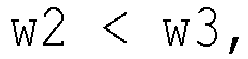


- Verfahren nach Anspruch 4 oder 5, wobei mindestens eine der folgenden Bedingungen gilt:



- Verfahren nach einem der Ansprüche 4 bis 6,
wobei die Grenzkurve ferner durch eine erste Linie (11) definiert ist, die dem ersten Rotordrehzahlwert entsprechende Rotordrehzahlwerte und Rotorbeschleunigungswerte aufweist, welche größer gleich dem ersten Rotorbeschleunigungswert sind,
wobei die Grenzkurve ferner durch eine fünfte Linie (15) definiert ist, die Rotordrehzahlwerte aufweist, welche größer gleich dem vierten Rotordrehzahlwert sind, und dem vierten Rotorbeschleunigungswert entsprechende Rotorbeschleunigungswerte aufweist. - Verfahren nach einem der Ansprüche 5 bis 7, wobei w3 einer kritischen Rotordrehzahl entspricht, über der der Rotor (403) auslegungsgemäß nicht arbeiten darf.
- Verfahren nach einem der Ansprüche 4 bis 8, wobei ein Einstellwinkel-Servosystem so betrieben wird, dass es Rotorblätter in eine Stoppposition bringt, wenn sich die Rotorbewegung der Grenzkurve (305) nähert.
- Verfahren nach einem der vorhergehenden Ansprüche, wobei das Bestimmen eines aktuellen Rotorbeschleunigungswerts das Messen des aktuellen Rotorbeschleunigungswerts insbesondere durch ein Gyroskop und/oder einen Beschleunigungsmesser umfasst.
- Anordnung (421) zum Regeln einer Rotorbewegung eines Rotors (403) einer Windenergieanlage (402), wobei die Anordnung Folgendes umfasst:einen Bestimmungsabschnitt, der so ausgelegt ist, dass er einen aktuellen Rotorbeschleunigungswert bestimmt,einen Regelabschnitt, der so ausgelegt ist, dass er die Rotorbewegung auf der Grundlage des gemessenen Rotorbeschleunigungswerts regelt,wobei das Regeln der Rotorbewegung so erfolgt, dass der Rotordrehzahlwert (301) und der Rotorbeschleunigungswert (303) in einem Satz (307) 2-Tupel, jedoch nicht außerhalb (309) des Satzes 2-Tupel liegen,
wobei der Satz (307) 2-Tupel als kontinuierlicher Bereich in einem Drehzahl/Rotorbeschleunigung-Koordinatensystem (301, 303) definiert ist,
wobei das Regeln der Rotorbewegung ferner auf einem aktuellen Rotordrehzahlwert (301) basiert, wobei Beschleunigungsgrenzwerte (a1, a2, a3, a4) in Abhängigkeit von der Rotordrehzahl (w1, w2, w3, w4) definiert sind,dadurch gekennzeichnet, dass bei einer relativ geringen Rotordrehzahl ein relativ hoher Rotorbeschleunigungswert toleriert wird, während bei einer relativ hohen Rotordrehzahl ein relativ geringer Rotorbeschleunigungswert toleriert wird. - Windenergieanlage (402), die Folgendes umfasst:einen Rotor (403),eine Anordnung (421) nach Anspruch 11 undein mit dem Regelabschnitt verbundenes Einstellwinkelregelsystem zum Verstellen eines Blatteinstellwinkels eines Blatts (405) zwecks Regeln der Rotorbewegung des Rotors (403).
Priority Applications (3)
| Application Number | Priority Date | Filing Date | Title |
|---|---|---|---|
| EP13184942.4A EP2851559B1 (de) | 2013-09-18 | 2013-09-18 | Verfahren und Anordnung zur Steuerung der Rotorbewegung eines Windturbinenrotors |
| ES13184942.4T ES2666069T3 (es) | 2013-09-18 | 2013-09-18 | Método y disposición para controlar un movimiento de rotor de un rotor de turbina eólica |
| DK13184942.4T DK2851559T3 (en) | 2013-09-18 | 2013-09-18 | Method and device for controlling the rotor movement of a wind turbine rotor |
Applications Claiming Priority (1)
| Application Number | Priority Date | Filing Date | Title |
|---|---|---|---|
| EP13184942.4A EP2851559B1 (de) | 2013-09-18 | 2013-09-18 | Verfahren und Anordnung zur Steuerung der Rotorbewegung eines Windturbinenrotors |
Publications (2)
| Publication Number | Publication Date |
|---|---|
| EP2851559A1 EP2851559A1 (de) | 2015-03-25 |
| EP2851559B1 true EP2851559B1 (de) | 2018-03-07 |
Family
ID=49223611
Family Applications (1)
| Application Number | Title | Priority Date | Filing Date |
|---|---|---|---|
| EP13184942.4A Not-in-force EP2851559B1 (de) | 2013-09-18 | 2013-09-18 | Verfahren und Anordnung zur Steuerung der Rotorbewegung eines Windturbinenrotors |
Country Status (3)
| Country | Link |
|---|---|
| EP (1) | EP2851559B1 (de) |
| DK (1) | DK2851559T3 (de) |
| ES (1) | ES2666069T3 (de) |
Families Citing this family (1)
| Publication number | Priority date | Publication date | Assignee | Title |
|---|---|---|---|---|
| US11072434B2 (en) * | 2018-04-24 | 2021-07-27 | Textron Innovations Inc. | Method and system for controlling rotor speeds of rotor systems |
Family Cites Families (4)
| Publication number | Priority date | Publication date | Assignee | Title |
|---|---|---|---|---|
| US4193005A (en) * | 1978-08-17 | 1980-03-11 | United Technologies Corporation | Multi-mode control system for wind turbines |
| DE102008012957A1 (de) * | 2008-03-06 | 2009-09-10 | Repower Systems Ag | Verfahren zum Betreiben einer Windenergieanlage und Windenergieanlage |
| DE102009011425B4 (de) * | 2009-03-03 | 2011-04-21 | Nordex Energy Gmbh | Verfahren zum Betreiben einer Windenergieanlage, die das Verfahren ausführt |
| EP2365215B1 (de) * | 2010-03-10 | 2012-12-12 | Siemens Aktiengesellschaft | Drehzahlsteuerung einer Windturbine basierend auf der Rotorbeschleunigung |
-
2013
- 2013-09-18 EP EP13184942.4A patent/EP2851559B1/de not_active Not-in-force
- 2013-09-18 DK DK13184942.4T patent/DK2851559T3/en active
- 2013-09-18 ES ES13184942.4T patent/ES2666069T3/es active Active
Non-Patent Citations (1)
| Title |
|---|
| None * |
Also Published As
| Publication number | Publication date |
|---|---|
| DK2851559T3 (en) | 2018-05-07 |
| ES2666069T3 (es) | 2018-04-30 |
| EP2851559A1 (de) | 2015-03-25 |
Similar Documents
| Publication | Publication Date | Title |
|---|---|---|
| US10612520B2 (en) | Rotational positioning system in a wind turbine | |
| EP2404058B1 (de) | Giersystem für eine windmühle | |
| EP2444659B1 (de) | Verfahren und System zur Einstellung eines Betriebsparameters für eine Windturbine | |
| EP2264315B1 (de) | Bedienung einer Windturbine bei Übertemperaturzustand des Motors | |
| EP2678556B1 (de) | Sicherheitssystem für eine windturbine | |
| EP2159415A2 (de) | Verfahren und Vorrichtung zur Steuerung des Gierwinkels einer Windenergieanlage | |
| EP2500562A2 (de) | Verfahren und System zur Verringerung der in Windturbinen durch Windasymmetrien entstehenden Belastungen | |
| EP2306005A2 (de) | Methode, um Vibrationen in Windturbinen zu reduzieren und Windturbine mit der gesagten Methode | |
| WO2011157271A2 (en) | A method and control unit for controlling a wind turbine in dependence on loading experienced by the wind turbine | |
| US20130193686A1 (en) | System and methods for determining pitch angles for a wind turbine during peak shaving | |
| EP2963286A1 (de) | Windturbine und verfahren zum anhalten davon | |
| EP2402600A2 (de) | Windturbine und Verfahren für den Betrieb einer Windturbine | |
| US20170248121A1 (en) | Wind turbine, yaw control device, and operation control method | |
| EP3054152B1 (de) | Vorrichtung zur windkrafterzeugung | |
| CN113795666B (zh) | 一种风力发电机及运行该风力发电机的方法 | |
| KR101363516B1 (ko) | 풍력 발전기용 발전기의 제어 방법 | |
| US10704533B2 (en) | Wind turbine power generating apparatus and method of operating the same | |
| EP3643916B1 (de) | System und verfahren zur überwachung des schaufelblattzustands von windturbinen | |
| EP2851559A1 (de) | Verfahren und Anordnung zur Steuerung der Rotorbewegung eines Windturbinenrotors | |
| JP2023129293A (ja) | 風力タービンの運転方法及び、補助装置への給電方法 | |
| TWI784667B (zh) | 在極端風力狀態下之風力渦輪機操作 | |
| EP4361434A1 (de) | Schutz von windturbinenkomponenten während des gierens | |
| KR101516546B1 (ko) | 풍력 발전기 및 그 제어방법 | |
| CN114837888A (zh) | 一种风机偏航辅助阵风穿越的控制系统及其控制方法 |
Legal Events
| Date | Code | Title | Description |
|---|---|---|---|
| PUAI | Public reference made under article 153(3) epc to a published international application that has entered the european phase |
Free format text: ORIGINAL CODE: 0009012 |
|
| 17P | Request for examination filed |
Effective date: 20130918 |
|
| AK | Designated contracting states |
Kind code of ref document: A1 Designated state(s): AL AT BE BG CH CY CZ DE DK EE ES FI FR GB GR HR HU IE IS IT LI LT LU LV MC MK MT NL NO PL PT RO RS SE SI SK SM TR |
|
| AX | Request for extension of the european patent |
Extension state: BA ME |
|
| R17P | Request for examination filed (corrected) |
Effective date: 20150306 |
|
| RBV | Designated contracting states (corrected) |
Designated state(s): AL AT BE BG CH CY CZ DE DK EE ES FI FR GB GR HR HU IE IS IT LI LT LU LV MC MK MT NL NO PL PT RO RS SE SI SK SM TR |
|
| 17Q | First examination report despatched |
Effective date: 20160629 |
|
| RAP1 | Party data changed (applicant data changed or rights of an application transferred) |
Owner name: SIEMENS AKTIENGESELLSCHAFT |
|
| GRAP | Despatch of communication of intention to grant a patent |
Free format text: ORIGINAL CODE: EPIDOSNIGR1 |
|
| INTG | Intention to grant announced |
Effective date: 20171027 |
|
| GRAS | Grant fee paid |
Free format text: ORIGINAL CODE: EPIDOSNIGR3 |
|
| GRAA | (expected) grant |
Free format text: ORIGINAL CODE: 0009210 |
|
| AK | Designated contracting states |
Kind code of ref document: B1 Designated state(s): AL AT BE BG CH CY CZ DE DK EE ES FI FR GB GR HR HU IE IS IT LI LT LU LV MC MK MT NL NO PL PT RO RS SE SI SK SM TR |
|
| REG | Reference to a national code |
Ref country code: GB Ref legal event code: FG4D |
|
| REG | Reference to a national code |
Ref country code: CH Ref legal event code: EP Ref country code: AT Ref legal event code: REF Ref document number: 976848 Country of ref document: AT Kind code of ref document: T Effective date: 20180315 |
|
| REG | Reference to a national code |
Ref country code: DE Ref legal event code: R096 Ref document number: 602013033960 Country of ref document: DE |
|
| REG | Reference to a national code |
Ref country code: IE Ref legal event code: FG4D |
|
| REG | Reference to a national code |
Ref country code: ES Ref legal event code: FG2A Ref document number: 2666069 Country of ref document: ES Kind code of ref document: T3 Effective date: 20180430 |
|
| REG | Reference to a national code |
Ref country code: DK Ref legal event code: T3 Effective date: 20180430 |
|
| REG | Reference to a national code |
Ref country code: NL Ref legal event code: MP Effective date: 20180307 |
|
| REG | Reference to a national code |
Ref country code: LT Ref legal event code: MG4D |
|
| PG25 | Lapsed in a contracting state [announced via postgrant information from national office to epo] |
Ref country code: LT Free format text: LAPSE BECAUSE OF FAILURE TO SUBMIT A TRANSLATION OF THE DESCRIPTION OR TO PAY THE FEE WITHIN THE PRESCRIBED TIME-LIMIT Effective date: 20180307 Ref country code: CY Free format text: LAPSE BECAUSE OF FAILURE TO SUBMIT A TRANSLATION OF THE DESCRIPTION OR TO PAY THE FEE WITHIN THE PRESCRIBED TIME-LIMIT Effective date: 20180307 Ref country code: FI Free format text: LAPSE BECAUSE OF FAILURE TO SUBMIT A TRANSLATION OF THE DESCRIPTION OR TO PAY THE FEE WITHIN THE PRESCRIBED TIME-LIMIT Effective date: 20180307 Ref country code: NO Free format text: LAPSE BECAUSE OF FAILURE TO SUBMIT A TRANSLATION OF THE DESCRIPTION OR TO PAY THE FEE WITHIN THE PRESCRIBED TIME-LIMIT Effective date: 20180607 Ref country code: HR Free format text: LAPSE BECAUSE OF FAILURE TO SUBMIT A TRANSLATION OF THE DESCRIPTION OR TO PAY THE FEE WITHIN THE PRESCRIBED TIME-LIMIT Effective date: 20180307 |
|
| REG | Reference to a national code |
Ref country code: AT Ref legal event code: MK05 Ref document number: 976848 Country of ref document: AT Kind code of ref document: T Effective date: 20180307 |
|
| PG25 | Lapsed in a contracting state [announced via postgrant information from national office to epo] |
Ref country code: RS Free format text: LAPSE BECAUSE OF FAILURE TO SUBMIT A TRANSLATION OF THE DESCRIPTION OR TO PAY THE FEE WITHIN THE PRESCRIBED TIME-LIMIT Effective date: 20180307 Ref country code: GR Free format text: LAPSE BECAUSE OF FAILURE TO SUBMIT A TRANSLATION OF THE DESCRIPTION OR TO PAY THE FEE WITHIN THE PRESCRIBED TIME-LIMIT Effective date: 20180608 Ref country code: BG Free format text: LAPSE BECAUSE OF FAILURE TO SUBMIT A TRANSLATION OF THE DESCRIPTION OR TO PAY THE FEE WITHIN THE PRESCRIBED TIME-LIMIT Effective date: 20180607 Ref country code: SE Free format text: LAPSE BECAUSE OF FAILURE TO SUBMIT A TRANSLATION OF THE DESCRIPTION OR TO PAY THE FEE WITHIN THE PRESCRIBED TIME-LIMIT Effective date: 20180307 Ref country code: LV Free format text: LAPSE BECAUSE OF FAILURE TO SUBMIT A TRANSLATION OF THE DESCRIPTION OR TO PAY THE FEE WITHIN THE PRESCRIBED TIME-LIMIT Effective date: 20180307 |
|
| PG25 | Lapsed in a contracting state [announced via postgrant information from national office to epo] |
Ref country code: RO Free format text: LAPSE BECAUSE OF FAILURE TO SUBMIT A TRANSLATION OF THE DESCRIPTION OR TO PAY THE FEE WITHIN THE PRESCRIBED TIME-LIMIT Effective date: 20180307 Ref country code: AL Free format text: LAPSE BECAUSE OF FAILURE TO SUBMIT A TRANSLATION OF THE DESCRIPTION OR TO PAY THE FEE WITHIN THE PRESCRIBED TIME-LIMIT Effective date: 20180307 Ref country code: PL Free format text: LAPSE BECAUSE OF FAILURE TO SUBMIT A TRANSLATION OF THE DESCRIPTION OR TO PAY THE FEE WITHIN THE PRESCRIBED TIME-LIMIT Effective date: 20180307 Ref country code: EE Free format text: LAPSE BECAUSE OF FAILURE TO SUBMIT A TRANSLATION OF THE DESCRIPTION OR TO PAY THE FEE WITHIN THE PRESCRIBED TIME-LIMIT Effective date: 20180307 Ref country code: NL Free format text: LAPSE BECAUSE OF FAILURE TO SUBMIT A TRANSLATION OF THE DESCRIPTION OR TO PAY THE FEE WITHIN THE PRESCRIBED TIME-LIMIT Effective date: 20180307 Ref country code: IT Free format text: LAPSE BECAUSE OF FAILURE TO SUBMIT A TRANSLATION OF THE DESCRIPTION OR TO PAY THE FEE WITHIN THE PRESCRIBED TIME-LIMIT Effective date: 20180307 |
|
| PG25 | Lapsed in a contracting state [announced via postgrant information from national office to epo] |
Ref country code: SM Free format text: LAPSE BECAUSE OF FAILURE TO SUBMIT A TRANSLATION OF THE DESCRIPTION OR TO PAY THE FEE WITHIN THE PRESCRIBED TIME-LIMIT Effective date: 20180307 Ref country code: SK Free format text: LAPSE BECAUSE OF FAILURE TO SUBMIT A TRANSLATION OF THE DESCRIPTION OR TO PAY THE FEE WITHIN THE PRESCRIBED TIME-LIMIT Effective date: 20180307 Ref country code: AT Free format text: LAPSE BECAUSE OF FAILURE TO SUBMIT A TRANSLATION OF THE DESCRIPTION OR TO PAY THE FEE WITHIN THE PRESCRIBED TIME-LIMIT Effective date: 20180307 Ref country code: CZ Free format text: LAPSE BECAUSE OF FAILURE TO SUBMIT A TRANSLATION OF THE DESCRIPTION OR TO PAY THE FEE WITHIN THE PRESCRIBED TIME-LIMIT Effective date: 20180307 |
|
| REG | Reference to a national code |
Ref country code: DE Ref legal event code: R097 Ref document number: 602013033960 Country of ref document: DE |
|
| PG25 | Lapsed in a contracting state [announced via postgrant information from national office to epo] |
Ref country code: PT Free format text: LAPSE BECAUSE OF FAILURE TO SUBMIT A TRANSLATION OF THE DESCRIPTION OR TO PAY THE FEE WITHIN THE PRESCRIBED TIME-LIMIT Effective date: 20180709 |
|
| PLBE | No opposition filed within time limit |
Free format text: ORIGINAL CODE: 0009261 |
|
| STAA | Information on the status of an ep patent application or granted ep patent |
Free format text: STATUS: NO OPPOSITION FILED WITHIN TIME LIMIT |
|
| 26N | No opposition filed |
Effective date: 20181210 |
|
| PG25 | Lapsed in a contracting state [announced via postgrant information from national office to epo] |
Ref country code: SI Free format text: LAPSE BECAUSE OF FAILURE TO SUBMIT A TRANSLATION OF THE DESCRIPTION OR TO PAY THE FEE WITHIN THE PRESCRIBED TIME-LIMIT Effective date: 20180307 |
|
| REG | Reference to a national code |
Ref country code: DE Ref legal event code: R119 Ref document number: 602013033960 Country of ref document: DE |
|
| PG25 | Lapsed in a contracting state [announced via postgrant information from national office to epo] |
Ref country code: MC Free format text: LAPSE BECAUSE OF FAILURE TO SUBMIT A TRANSLATION OF THE DESCRIPTION OR TO PAY THE FEE WITHIN THE PRESCRIBED TIME-LIMIT Effective date: 20180307 |
|
| REG | Reference to a national code |
Ref country code: CH Ref legal event code: PL |
|
| REG | Reference to a national code |
Ref country code: DK Ref legal event code: EBP Effective date: 20180930 |
|
| GBPC | Gb: european patent ceased through non-payment of renewal fee |
Effective date: 20180918 |
|
| REG | Reference to a national code |
Ref country code: BE Ref legal event code: MM Effective date: 20180930 |
|
| REG | Reference to a national code |
Ref country code: IE Ref legal event code: MM4A |
|
| PG25 | Lapsed in a contracting state [announced via postgrant information from national office to epo] |
Ref country code: LU Free format text: LAPSE BECAUSE OF NON-PAYMENT OF DUE FEES Effective date: 20180918 |
|
| PG25 | Lapsed in a contracting state [announced via postgrant information from national office to epo] |
Ref country code: IE Free format text: LAPSE BECAUSE OF NON-PAYMENT OF DUE FEES Effective date: 20180918 Ref country code: DE Free format text: LAPSE BECAUSE OF NON-PAYMENT OF DUE FEES Effective date: 20190402 |
|
| PG25 | Lapsed in a contracting state [announced via postgrant information from national office to epo] |
Ref country code: CH Free format text: LAPSE BECAUSE OF NON-PAYMENT OF DUE FEES Effective date: 20180930 Ref country code: LI Free format text: LAPSE BECAUSE OF NON-PAYMENT OF DUE FEES Effective date: 20180930 Ref country code: FR Free format text: LAPSE BECAUSE OF NON-PAYMENT OF DUE FEES Effective date: 20180930 Ref country code: BE Free format text: LAPSE BECAUSE OF NON-PAYMENT OF DUE FEES Effective date: 20180930 |
|
| REG | Reference to a national code |
Ref country code: ES Ref legal event code: FD2A Effective date: 20191030 |
|
| PG25 | Lapsed in a contracting state [announced via postgrant information from national office to epo] |
Ref country code: DK Free format text: LAPSE BECAUSE OF NON-PAYMENT OF DUE FEES Effective date: 20180930 Ref country code: GB Free format text: LAPSE BECAUSE OF NON-PAYMENT OF DUE FEES Effective date: 20180918 |
|
| PG25 | Lapsed in a contracting state [announced via postgrant information from national office to epo] |
Ref country code: MT Free format text: LAPSE BECAUSE OF NON-PAYMENT OF DUE FEES Effective date: 20180918 |
|
| PG25 | Lapsed in a contracting state [announced via postgrant information from national office to epo] |
Ref country code: ES Free format text: LAPSE BECAUSE OF NON-PAYMENT OF DUE FEES Effective date: 20180919 |
|
| PG25 | Lapsed in a contracting state [announced via postgrant information from national office to epo] |
Ref country code: TR Free format text: LAPSE BECAUSE OF FAILURE TO SUBMIT A TRANSLATION OF THE DESCRIPTION OR TO PAY THE FEE WITHIN THE PRESCRIBED TIME-LIMIT Effective date: 20180307 |
|
| PG25 | Lapsed in a contracting state [announced via postgrant information from national office to epo] |
Ref country code: HU Free format text: LAPSE BECAUSE OF FAILURE TO SUBMIT A TRANSLATION OF THE DESCRIPTION OR TO PAY THE FEE WITHIN THE PRESCRIBED TIME-LIMIT; INVALID AB INITIO Effective date: 20130918 |
|
| PG25 | Lapsed in a contracting state [announced via postgrant information from national office to epo] |
Ref country code: MK Free format text: LAPSE BECAUSE OF NON-PAYMENT OF DUE FEES Effective date: 20180307 |
|
| PG25 | Lapsed in a contracting state [announced via postgrant information from national office to epo] |
Ref country code: IS Free format text: LAPSE BECAUSE OF FAILURE TO SUBMIT A TRANSLATION OF THE DESCRIPTION OR TO PAY THE FEE WITHIN THE PRESCRIBED TIME-LIMIT Effective date: 20180707 |