EP2851579A1 - Agencement de couplage doté de réducteur de vibrations - Google Patents
Agencement de couplage doté de réducteur de vibrations Download PDFInfo
- Publication number
- EP2851579A1 EP2851579A1 EP14181714.8A EP14181714A EP2851579A1 EP 2851579 A1 EP2851579 A1 EP 2851579A1 EP 14181714 A EP14181714 A EP 14181714A EP 2851579 A1 EP2851579 A1 EP 2851579A1
- Authority
- EP
- European Patent Office
- Prior art keywords
- vibration damper
- torsional vibration
- absorber
- friction
- output
- Prior art date
- Legal status (The legal status is an assumption and is not a legal conclusion. Google has not performed a legal analysis and makes no representation as to the accuracy of the status listed.)
- Withdrawn
Links
- 230000008878 coupling Effects 0.000 title claims abstract description 24
- 238000010168 coupling process Methods 0.000 title claims abstract description 24
- 238000005859 coupling reaction Methods 0.000 title claims abstract description 24
- 230000005540 biological transmission Effects 0.000 claims abstract description 21
- 238000002485 combustion reaction Methods 0.000 claims abstract description 9
- 239000006096 absorbing agent Substances 0.000 claims description 38
- 230000000694 effects Effects 0.000 claims description 5
- 230000009471 action Effects 0.000 claims description 4
- 230000008901 benefit Effects 0.000 description 3
- 230000010355 oscillation Effects 0.000 description 3
- 230000008859 change Effects 0.000 description 2
- 230000007246 mechanism Effects 0.000 description 2
- 230000006978 adaptation Effects 0.000 description 1
- 238000010276 construction Methods 0.000 description 1
- 230000001419 dependent effect Effects 0.000 description 1
- 238000010586 diagram Methods 0.000 description 1
Images


Classifications
-
- F—MECHANICAL ENGINEERING; LIGHTING; HEATING; WEAPONS; BLASTING
- F16—ENGINEERING ELEMENTS AND UNITS; GENERAL MEASURES FOR PRODUCING AND MAINTAINING EFFECTIVE FUNCTIONING OF MACHINES OR INSTALLATIONS; THERMAL INSULATION IN GENERAL
- F16F—SPRINGS; SHOCK-ABSORBERS; MEANS FOR DAMPING VIBRATION
- F16F15/00—Suppression of vibrations in systems; Means or arrangements for avoiding or reducing out-of-balance forces, e.g. due to motion
- F16F15/10—Suppression of vibrations in rotating systems by making use of members moving with the system
- F16F15/14—Suppression of vibrations in rotating systems by making use of members moving with the system using masses freely rotating with the system, i.e. uninvolved in transmitting driveline torque, e.g. rotative dynamic dampers
- F16F15/1407—Suppression of vibrations in rotating systems by making use of members moving with the system using masses freely rotating with the system, i.e. uninvolved in transmitting driveline torque, e.g. rotative dynamic dampers the rotation being limited with respect to the driving means
- F16F15/145—Masses mounted with play with respect to driving means thus enabling free movement over a limited range
-
- F—MECHANICAL ENGINEERING; LIGHTING; HEATING; WEAPONS; BLASTING
- F16—ENGINEERING ELEMENTS AND UNITS; GENERAL MEASURES FOR PRODUCING AND MAINTAINING EFFECTIVE FUNCTIONING OF MACHINES OR INSTALLATIONS; THERMAL INSULATION IN GENERAL
- F16F—SPRINGS; SHOCK-ABSORBERS; MEANS FOR DAMPING VIBRATION
- F16F15/00—Suppression of vibrations in systems; Means or arrangements for avoiding or reducing out-of-balance forces, e.g. due to motion
- F16F15/10—Suppression of vibrations in rotating systems by making use of members moving with the system
- F16F15/12—Suppression of vibrations in rotating systems by making use of members moving with the system using elastic members or friction-damping members, e.g. between a rotating shaft and a gyratory mass mounted thereon
- F16F15/121—Suppression of vibrations in rotating systems by making use of members moving with the system using elastic members or friction-damping members, e.g. between a rotating shaft and a gyratory mass mounted thereon using springs as elastic members, e.g. metallic springs
- F16F15/123—Wound springs
- F16F15/12313—Wound springs characterised by the dimension or shape of spring-containing windows
-
- F—MECHANICAL ENGINEERING; LIGHTING; HEATING; WEAPONS; BLASTING
- F16—ENGINEERING ELEMENTS AND UNITS; GENERAL MEASURES FOR PRODUCING AND MAINTAINING EFFECTIVE FUNCTIONING OF MACHINES OR INSTALLATIONS; THERMAL INSULATION IN GENERAL
- F16F—SPRINGS; SHOCK-ABSORBERS; MEANS FOR DAMPING VIBRATION
- F16F15/00—Suppression of vibrations in systems; Means or arrangements for avoiding or reducing out-of-balance forces, e.g. due to motion
- F16F15/10—Suppression of vibrations in rotating systems by making use of members moving with the system
- F16F15/12—Suppression of vibrations in rotating systems by making use of members moving with the system using elastic members or friction-damping members, e.g. between a rotating shaft and a gyratory mass mounted thereon
- F16F15/129—Suppression of vibrations in rotating systems by making use of members moving with the system using elastic members or friction-damping members, e.g. between a rotating shaft and a gyratory mass mounted thereon characterised by friction-damping means
Definitions
- the present invention relates to a clutch assembly for transmitting torque from a drive unit, in particular an internal combustion engine of a motor vehicle, to an output unit, in particular a transmission with at least one coupling device, a torsional vibration damper and a vibration damper, and a drive train arrangement with such a clutch arrangement.
- Coupling arrangements are known from the prior art, which can be used in combination with a vibration damper.
- the clutch plates can be firmly connected directly to the vibration damper, wherein the vibration damper can be arranged in the direction of action before or after the torsional vibration damper.
- the arrangement of the vibration absorber before the torsional vibration damper clearly preferred, since it has been found that it is structurally unfavorable to arrange the absorber masses on the secondary side of the torsional vibration damper.
- Object of the present invention is therefore to provide a clutch assembly with secondary side mounted vibration absorber, which allows a normal design of the transmission.
- a clutch arrangement for transmitting a torque from a drive unit, in particular an internal combustion engine of a motor vehicle, to an output unit, in particular a transmission, with at least one coupling device, which is connected on the input side to an output shaft of the drive unit and the output side to an input of a torsional vibration damper.
- the torsional vibration damper itself is connected on the output side via a friction device with a vibration damper.
- the present invention is based on the idea of designing the clutch arrangement such that at low angles of rotation, in particular around the zero point of the torsional vibration damper, the torsional vibration damper has a substantially flat spring characteristic and / or the friction device has low friction.
- the flat spring characteristic can be achieved in that at least one spring element of the torsional vibration damper is arranged substantially without bias or only with low bias against an output-side member of the coupling device.
- a torsional moment of approximately 0 Nm is preferably provided at a twist angle of approximately 0 °. Due to the flat characteristic of the vibration absorber can work optimally with the coupling device.
- the flat characteristic corresponds to a low rigidity of the torsional vibration damper around the zero point.
- the characteristic curve may have a step and / or at least one further region with a strongly increasing characteristic curve.
- a preloaded spring element would cause the moment to make a jump at zero point, whereas a spring that is inserted too loosely requires a certain angle of rotation until the moment increases.
- the output-side component has at least one spring window having a first and a second edge, which at least partially contacts the spring element. It is particularly provided that the first and / or the second edge contacted at small angles of rotation, the spring element only at its radially inner edge. As a result, the force provided by the spring element around the zero point is relatively low, since the spring element is initially loaded only on one side. As the rotation increases, the edge also contacts the radially outer portions of the spring member, thereby requiring more force for further rotation. As a result, in particular a stepped torsional vibration damper characteristic can be provided.
- the friction device can be designed as a control plate friction or as a ramp friction device. It is particularly advantageous if the friction increases continuously with increasing angle of rotation.
- the vibration damper on at least one means of a fastener on a Tilgerthere arranged absorber mass is designed such that its Tilgerowski is below the engine order, preferably the Tilgerowski is reduced from a Tilgermassenauslenkung in the range of 25 ° -50 °, preferably at about 30 °.
- the vibration damper is designed as a speed-adaptive vibration absorber. It is particularly preferred if the Tilgeritati and / or the absorber mass show an opening whose shape defines a vibrational orbit of the absorber mass.
- the web preferably runs, viewed from its vertex, flatter than a web which is designed for optimum action.
- Another aspect of the present invention relates to a drive train arrangement with a drive unit, in particular an internal combustion engine of a motor vehicle, and an output unit, in particular a transmission, wherein for transmitting a torque from the drive unit to the output unit, a clutch arrangement, as described above, is provided.
- the clutch assembly has its optimum effect, in particular, when a rigidity of a vehicle side shaft, such as a wheel drive shaft, which is significantly affecting the rigidity of the drive train, is as high as possible in comparison to the stiffness of the clutch disc.
- a side shaft which transmits torque from the drive unit to a wheel, wherein an effective stiffness of the side shaft at least 2-fold, more preferably about 4-fold or 5-fold as high as a stiffness of the torsional vibration damper is. It is not the actual stiffness, but an effective stiffness of the side wave relevant.
- the effective stiffness C eff results from the real rigidity of the side shaft C SW and the gear ratio including differential i tot .
- C eff C SW / i ges 2 is defined. It is particularly preferred if the effective stiffness of the side shafts in the highest gear of the transmission is at least 4 times, preferably even 5 times greater than the real stiffness of the torsional vibration damper of the clutch assembly.
- the drive train is designed such that the total moment of inertia J ges of the drive train a maximum of about 15 times, preferably 10 times greater than the mass moment of inertia J T of the absorber masses of the vibration absorber.
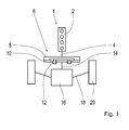
- Fig. 1 schematically shows a drive train 1 with an internal combustion engine 2, whose torque is transmitted via an output shaft 4, in particular a crankshaft, to a clutch assembly 6.
- the clutch assembly 6 further includes a non-rotatably connected to the crankshaft 4 flywheel 8, which in turn is connected to a clutch disc 10 with torsional vibration damper 12.
- the torsional vibration damper 12 is effective after the clutch disc 10th arranged. From the torsional vibration damper 12, the torque is further introduced to a transmission input shaft 14, from where it is transferred to a transmission 16.
- the transmission 16 itself translates the rotational motion by means of the various gears and outputs them to side shafts 18, which in turn are connected to wheels 20.
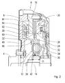
- a clutch assembly 6 As clutch assembly 6, a clutch assembly 6 according to the invention is used, which schematically in Fig. 2 is shown. It also shows Fig. 2 schematically the flywheel 8, which is rotatably connected to the crankshaft 4 and the torque to an input side of the coupling device 10 passes.
- the coupling device 10 is designed as a friction clutch with a clutch disc 22, which in a known manner a hub disc 24 with non-rotatably mounted friction linings 26 has.
- the friction linings 26 are defined between a pressure plate 28 and the pressure plate 30 by means of the clutch actuating mechanism 32 to transmit torque from the flywheel 8 to the transmission input shaft 14.
- a torsional vibration damper 12 the input side of which is formed over the hub disc 24, is further arranged between the hub disc 24 and the transmission input shaft 14.
- the torsional vibration damper 12 also has spring elements 34, the rotation between the hub disc 24 and cover plates 36; 38 of the torsional vibration damper 12 dampen.
- Fig. 2 on the output side of the torsional vibration damper, which is represented by the cover plates 36, 38, on the cover plate 38 there is furthermore provided a vibration damper 40 which, in a known manner, absorbs vibrations in the drive train.
- the vibration damper 40 according to the invention is technically arranged after the torsional vibration damper 12.
- a friction device 42 is provided between hub disc 24 and cover plate 38, which additionally counteracts a rotation between hub disc 24 and cover plates 36, 38.
- the vibration damper 40 is structurally arranged after the torsional vibration damper 12, the gear 16 had to be designed for the additional mass in the prior art.
- the torsional vibration damper 12 and / or the friction device 42 are formed such that by a small VerFDwinkel Scheme mainly coupling device 10 and vibration absorber 40 cooperate, can be dispensed with such a design of the transmission 16.
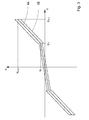
- the torsional vibration damper 12 such as Fig. 3 shows a flat in a range around the zero line characteristic.
- Fig. 3 schematically shows the torsional moment M on the y-axis, which is plotted for each angle of rotation ⁇ of the x-axis. It shows Fig. 3 in that, in a range from 0 to a twist angle ⁇ 1, the characteristic curve 44 has only a slight slope and also the torsional moment M increases only up to a first value M 1 .
- This value M 1 is comparatively small compared to a maximum torsional moment M END , which is achieved at a maximum angle of rotation of ⁇ END .
- the rigidity of the torsional vibration damper 12 in this region is also low.
- the friction is shown as a dashed line 46, which, as usual, also in the form of a hysteresis.
- the slope or configuration of the characteristic area between ⁇ 1 and ⁇ END which adjoins the flat area between 0 and ⁇ 1 can be chosen freely and, instead of as in FIG Fig. 3 shown to increase linearly, also contain other stages.
- Fig. 4 shows the hub disc 24 windows 50 having a first edge 52 and a second edge 54 which contact the spring element 34. It shows Fig. 4 in that, in the rest position, the spring element 34 only comes into contact with the edge 52 at its radially inner region 56. Only from an angle of rotation of ⁇ 1 contacted the edge 52 and the radially outer portion 58 of the spring element 52 so that the entire spring element 32 is charged for a further rotation. In a twist angle from 0 to ⁇ 1, however, only the radially inner portion 56 of the spring element 34 is loaded, so that in the end the characteristic curve 44 results, which is initially, ie up to an angle of ⁇ 1, flat and steeper from the angle ⁇ 1.
- angle-dependent increase in friction can be achieved for example in a known manner via a Rampenreib driving or Steuerblechreibung.
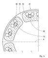
- Fig. 5 schematically shows a plan view of the inventive, in Fig. 2 shown vibration absorber 40, wherein the vibration damper 40, as the Figures 2 and 5 can be seen, a Tilgercomparatively 60, to which via coupling bolts 62 Tilgermassen 64 are attached.
- the Tilgerities 60 is in turn, as Fig. 2 shows rotatably connected via a mounting 66 with the Torsionsdeckblech 38.
- the supervision off Fig. 5 on the vibration absorber 40 further shows that at the absorber masses 64 or on the support plate 60 openings 68 are formed, which are designed such that the absorber masses 64 can oscillate on a curved path.
- the path defined via the opening 68 is designed in such a way that, viewed from its vertex 70, the path is flatter than would require design for the optimum effect.
- the course of the Tilgerowski is designed shortly below the engine main order, which is done via a corresponding adjustment of the Tilgerbahnen, as described above.
- Fig. 6 shows Fig. 6 in that, starting at an angle of oscillation ⁇ of approximately 30 °, the absorber arrangement is lowered further in order to achieve a stable oscillation behavior of the vibration absorber 40.
- the additional lowering serves in particular the mechanical protection of the vibration absorber 40th
- the coupling assembly 6 according to the invention then on when a substantially acting on a rigidity of the drive train 2 stiffness of the vehicle side shaft 18 in comparison to the rigidity of the coupling device 6 is as high as possible.
- an effective stiffness of the side shafts 18 should be considered. This results from the real rigidity of the side shafts 18 and the gear ratio including differential.
- the effective stiffness of the side shafts 18 in the highest gear of the transmission 16 should be at least 4 times, preferably 5 times greater than a real rigidity of the torsional vibration damper 12.
- the construction has a particularly good effect when the force acting on the inertia of the drive train substantially Mass inertia J ges with closed clutch device 6 in a certain gear at most a factor 10 times greater than the mass inertia of the absorber masses J T.
- the mass moment of inertia of the drive train J ges is defined as the sum of the effective individual inertias J eff , which results from the real inertia J of each part and the ratio i between the component and the transmission input shaft.
- the total moment of inertia of the drive train J ges up to 15 times, preferably 10 times greater than the moment of inertia of the absorber masses J T.
Landscapes
- Engineering & Computer Science (AREA)
- General Engineering & Computer Science (AREA)
- Physics & Mathematics (AREA)
- Acoustics & Sound (AREA)
- Aviation & Aerospace Engineering (AREA)
- Mechanical Engineering (AREA)
- Mechanical Operated Clutches (AREA)
Applications Claiming Priority (1)
| Application Number | Priority Date | Filing Date | Title |
|---|---|---|---|
| DE102013219162.6A DE102013219162A1 (de) | 2013-09-24 | 2013-09-24 | Kupplungsanordnung mit Schwingungstilger |
Publications (1)
| Publication Number | Publication Date |
|---|---|
| EP2851579A1 true EP2851579A1 (fr) | 2015-03-25 |
Family
ID=51383619
Family Applications (1)
| Application Number | Title | Priority Date | Filing Date |
|---|---|---|---|
| EP14181714.8A Withdrawn EP2851579A1 (fr) | 2013-09-24 | 2014-08-21 | Agencement de couplage doté de réducteur de vibrations |
Country Status (2)
| Country | Link |
|---|---|
| EP (1) | EP2851579A1 (fr) |
| DE (1) | DE102013219162A1 (fr) |
Cited By (7)
| Publication number | Priority date | Publication date | Assignee | Title |
|---|---|---|---|---|
| WO2016087411A1 (fr) * | 2014-12-03 | 2016-06-09 | Voith Patent Gmbh | Amortisseur de vibrations de torsion |
| WO2017191374A1 (fr) * | 2016-05-03 | 2017-11-09 | Valeo Embrayages | Ensemble amortisseur pour un véhicule automobile et appareil hydrocinétique comprenant un tel ensemble |
| WO2017191399A1 (fr) * | 2016-05-03 | 2017-11-09 | Valeo Embrayages | Ensemble amortisseur pour un véhicule automobile et appareil hydrocinetique comprenant un tel ensemble |
| CN107463717A (zh) * | 2016-06-03 | 2017-12-12 | 罗伯特·博世有限公司 | 用于求取传动系的总质量惯性矩的方法 |
| FR3063318A1 (fr) * | 2017-02-24 | 2018-08-31 | Valeo Embrayages | Systeme de transmission de couple comportant un amortisseur a organe elastique et un amortisseur pendulaire |
| US20180313427A1 (en) * | 2015-10-20 | 2018-11-01 | Zf Friedrichshafen Ag | Absorber System With Guideways And Method For The Arrangement Of Guideways On An Absorber System |
| WO2020052710A1 (fr) * | 2018-09-14 | 2020-03-19 | Schaeffler Technologies AG & Co. KG | Amortisseur de vibrations de torsion |
Families Citing this family (1)
| Publication number | Priority date | Publication date | Assignee | Title |
|---|---|---|---|---|
| DE102014214013B4 (de) * | 2014-07-18 | 2024-05-29 | Schaeffler Technologies AG & Co. KG | Reibungskupplungseinrichtung |
Citations (4)
| Publication number | Priority date | Publication date | Assignee | Title |
|---|---|---|---|---|
| DE19654894A1 (de) | 1996-03-12 | 1997-12-04 | Mannesmann Sachs Ag | Torsionsschwingungsdämpfer mit einer Ausgleichsschwungmasse |
| DE10110671A1 (de) * | 2001-03-06 | 2002-09-12 | Zf Sachs Ag | Verfahren zum Ermitteln wenigstens einer für die Betriebscharakteristik einer Schwingungsdämpfungseinrichtung relevanten Größe |
| US20050023103A1 (en) * | 2003-08-01 | 2005-02-03 | Exedy Corporation | Damper mechanism for a lockup clutch |
| DE102011006533A1 (de) * | 2010-05-07 | 2011-11-10 | Zf Friedrichshafen Ag | Drehmomentübertragungsbaugruppe, insbesondere hydrodynamischer Drehmomentwandler, Fluidkupplung oder nasslaufende Kupplung |
Family Cites Families (3)
| Publication number | Priority date | Publication date | Assignee | Title |
|---|---|---|---|---|
| DE3741701A1 (de) * | 1987-12-09 | 1989-06-22 | Fichtel & Sachs Ag | Geteiltes schwungrad mit zusatzmasse |
| FR2669088B1 (fr) * | 1990-11-08 | 1993-12-10 | Valeo | Embrayage pour transmission a amortisseur dynamique de vibrations, notamment de vehicules automobiles. |
| DE10210397B4 (de) * | 2002-03-08 | 2014-11-20 | Zf Friedrichshafen Ag | Torsionsschwingungsdämpfer |
-
2013
- 2013-09-24 DE DE102013219162.6A patent/DE102013219162A1/de not_active Ceased
-
2014
- 2014-08-21 EP EP14181714.8A patent/EP2851579A1/fr not_active Withdrawn
Patent Citations (4)
| Publication number | Priority date | Publication date | Assignee | Title |
|---|---|---|---|---|
| DE19654894A1 (de) | 1996-03-12 | 1997-12-04 | Mannesmann Sachs Ag | Torsionsschwingungsdämpfer mit einer Ausgleichsschwungmasse |
| DE10110671A1 (de) * | 2001-03-06 | 2002-09-12 | Zf Sachs Ag | Verfahren zum Ermitteln wenigstens einer für die Betriebscharakteristik einer Schwingungsdämpfungseinrichtung relevanten Größe |
| US20050023103A1 (en) * | 2003-08-01 | 2005-02-03 | Exedy Corporation | Damper mechanism for a lockup clutch |
| DE102011006533A1 (de) * | 2010-05-07 | 2011-11-10 | Zf Friedrichshafen Ag | Drehmomentübertragungsbaugruppe, insbesondere hydrodynamischer Drehmomentwandler, Fluidkupplung oder nasslaufende Kupplung |
Cited By (8)
| Publication number | Priority date | Publication date | Assignee | Title |
|---|---|---|---|---|
| WO2016087411A1 (fr) * | 2014-12-03 | 2016-06-09 | Voith Patent Gmbh | Amortisseur de vibrations de torsion |
| US20180313427A1 (en) * | 2015-10-20 | 2018-11-01 | Zf Friedrichshafen Ag | Absorber System With Guideways And Method For The Arrangement Of Guideways On An Absorber System |
| US10605326B2 (en) * | 2015-10-20 | 2020-03-31 | Zf Friedrichshafen Ag | Absorber system with guideways and method for the arrangement of guideways on an absorber system |
| WO2017191374A1 (fr) * | 2016-05-03 | 2017-11-09 | Valeo Embrayages | Ensemble amortisseur pour un véhicule automobile et appareil hydrocinétique comprenant un tel ensemble |
| WO2017191399A1 (fr) * | 2016-05-03 | 2017-11-09 | Valeo Embrayages | Ensemble amortisseur pour un véhicule automobile et appareil hydrocinetique comprenant un tel ensemble |
| CN107463717A (zh) * | 2016-06-03 | 2017-12-12 | 罗伯特·博世有限公司 | 用于求取传动系的总质量惯性矩的方法 |
| FR3063318A1 (fr) * | 2017-02-24 | 2018-08-31 | Valeo Embrayages | Systeme de transmission de couple comportant un amortisseur a organe elastique et un amortisseur pendulaire |
| WO2020052710A1 (fr) * | 2018-09-14 | 2020-03-19 | Schaeffler Technologies AG & Co. KG | Amortisseur de vibrations de torsion |
Also Published As
| Publication number | Publication date |
|---|---|
| DE102013219162A1 (de) | 2015-03-26 |
Similar Documents
| Publication | Publication Date | Title |
|---|---|---|
| EP2851579A1 (fr) | Agencement de couplage doté de réducteur de vibrations | |
| DE112008002980B4 (de) | Drehmomentwandler mit Turbinen-Massentilger | |
| DE102011076790B4 (de) | Antriebssystem für ein Fahrzeug | |
| DE19522225B4 (de) | Torsionsschwingungsdämpfer | |
| DE3448587C2 (de) | Kupplungsscheibe mit Torsionsschwingungsdämpfer | |
| WO2010063251A1 (fr) | Amortisseur de vibrations de torsion | |
| WO2008098536A2 (fr) | Dispositif pendulaire à force centrifuge | |
| WO2013034125A1 (fr) | Pendule centrifuge et disque d'embrayage doté dudit pendule centrifuge | |
| EP3198169A1 (fr) | Disque d'embrayage muni d'un amortisseur des vibrations de torsion | |
| DE102011004443A1 (de) | Schwingungsdämpfungseinrichtung | |
| EP1988306A2 (fr) | Disque de couplage | |
| DE102019118220A1 (de) | Antriebseinrichtung für einen hybridischen Antriebsstrang | |
| DE102020127459A1 (de) | Pendelwippendämpfer mit mehrteiligem Wippenelement; sowie Hybridantriebsstrang | |
| DE102012209897A1 (de) | Nabeneinrichtung für einen Torsionsschwingungsdämpfer und entsprechender Torsionsschwingungsdämpfer | |
| DE10210619A1 (de) | Dämpfungsvorrichtung | |
| DE102009049879A1 (de) | Schwingungstilger zur Dämpfung von Drehschwingungen im Antriebsstrang eines Kraftfahrzeugs | |
| DE102021112758B3 (de) | Pendelwippendämpfer mit radial innenliegenden Anschlägen | |
| DE112017004158T5 (de) | Dämpfervorrichtung | |
| EP2743542A2 (fr) | Systèmes d'accouplement | |
| WO2014012547A2 (fr) | Amortisseur de vibrations, en particulier pour un véhicule automobile, embrayage à friction correspondant et véhicule correspondant | |
| DE10319784A1 (de) | Integriertes Drehgeschwindigkeitsdämpfer-Bauteil für einen Antriebsstrang | |
| DE3442717A1 (de) | Kupplungsscheibe | |
| WO2015018413A1 (fr) | Amortisseur de vibrations en torsion | |
| DE102016211220A1 (de) | Kupplungsscheibe und Reibungskupplungseinrichtung | |
| DE102008049105A1 (de) | Schwungrad |
Legal Events
| Date | Code | Title | Description |
|---|---|---|---|
| PUAI | Public reference made under article 153(3) epc to a published international application that has entered the european phase |
Free format text: ORIGINAL CODE: 0009012 |
|
| 17P | Request for examination filed |
Effective date: 20140821 |
|
| AK | Designated contracting states |
Kind code of ref document: A1 Designated state(s): AL AT BE BG CH CY CZ DE DK EE ES FI FR GB GR HR HU IE IS IT LI LT LU LV MC MK MT NL NO PL PT RO RS SE SI SK SM TR |
|
| AX | Request for extension of the european patent |
Extension state: BA ME |
|
| R17P | Request for examination filed (corrected) |
Effective date: 20150622 |
|
| 17Q | First examination report despatched |
Effective date: 20161007 |
|
| GRAP | Despatch of communication of intention to grant a patent |
Free format text: ORIGINAL CODE: EPIDOSNIGR1 |
|
| INTG | Intention to grant announced |
Effective date: 20171027 |
|
| STAA | Information on the status of an ep patent application or granted ep patent |
Free format text: STATUS: THE APPLICATION IS DEEMED TO BE WITHDRAWN |
|
| 18D | Application deemed to be withdrawn |
Effective date: 20180301 |