EP2851612B1 - Lampe dotée d'un abat-jour - Google Patents
Lampe dotée d'un abat-jour Download PDFInfo
- Publication number
- EP2851612B1 EP2851612B1 EP13004636.0A EP13004636A EP2851612B1 EP 2851612 B1 EP2851612 B1 EP 2851612B1 EP 13004636 A EP13004636 A EP 13004636A EP 2851612 B1 EP2851612 B1 EP 2851612B1
- Authority
- EP
- European Patent Office
- Prior art keywords
- lampshade
- lamp
- light
- recessed portion
- inwardly recessed
- Prior art date
- Legal status (The legal status is an assumption and is not a legal conclusion. Google has not performed a legal analysis and makes no representation as to the accuracy of the status listed.)
- Active
Links
Images

Classifications
-
- F—MECHANICAL ENGINEERING; LIGHTING; HEATING; WEAPONS; BLASTING
- F21—LIGHTING
- F21V—FUNCTIONAL FEATURES OR DETAILS OF LIGHTING DEVICES OR SYSTEMS THEREOF; STRUCTURAL COMBINATIONS OF LIGHTING DEVICES WITH OTHER ARTICLES, NOT OTHERWISE PROVIDED FOR
- F21V1/00—Shades for light sources, i.e. lampshades for table, floor, wall or ceiling lamps
-
- F—MECHANICAL ENGINEERING; LIGHTING; HEATING; WEAPONS; BLASTING
- F21—LIGHTING
- F21K—NON-ELECTRIC LIGHT SOURCES USING LUMINESCENCE; LIGHT SOURCES USING ELECTROCHEMILUMINESCENCE; LIGHT SOURCES USING CHARGES OF COMBUSTIBLE MATERIAL; LIGHT SOURCES USING SEMICONDUCTOR DEVICES AS LIGHT-GENERATING ELEMENTS; LIGHT SOURCES NOT OTHERWISE PROVIDED FOR
- F21K9/00—Light sources using semiconductor devices as light-generating elements, e.g. using light-emitting diodes [LED] or lasers
- F21K9/20—Light sources comprising attachment means
-
- F—MECHANICAL ENGINEERING; LIGHTING; HEATING; WEAPONS; BLASTING
- F21—LIGHTING
- F21S—NON-PORTABLE LIGHTING DEVICES; SYSTEMS THEREOF; VEHICLE LIGHTING DEVICES SPECIALLY ADAPTED FOR VEHICLE EXTERIORS
- F21S8/00—Lighting devices intended for fixed installation
- F21S8/04—Lighting devices intended for fixed installation intended only for mounting on a ceiling or the like overhead structures
- F21S8/06—Lighting devices intended for fixed installation intended only for mounting on a ceiling or the like overhead structures by suspension
-
- F—MECHANICAL ENGINEERING; LIGHTING; HEATING; WEAPONS; BLASTING
- F21—LIGHTING
- F21V—FUNCTIONAL FEATURES OR DETAILS OF LIGHTING DEVICES OR SYSTEMS THEREOF; STRUCTURAL COMBINATIONS OF LIGHTING DEVICES WITH OTHER ARTICLES, NOT OTHERWISE PROVIDED FOR
- F21V1/00—Shades for light sources, i.e. lampshades for table, floor, wall or ceiling lamps
- F21V1/14—Covers for frames; Frameless shades
- F21V1/146—Frameless shades
-
- F—MECHANICAL ENGINEERING; LIGHTING; HEATING; WEAPONS; BLASTING
- F21—LIGHTING
- F21V—FUNCTIONAL FEATURES OR DETAILS OF LIGHTING DEVICES OR SYSTEMS THEREOF; STRUCTURAL COMBINATIONS OF LIGHTING DEVICES WITH OTHER ARTICLES, NOT OTHERWISE PROVIDED FOR
- F21V3/00—Globes; Bowls; Cover glasses
-
- F—MECHANICAL ENGINEERING; LIGHTING; HEATING; WEAPONS; BLASTING
- F21—LIGHTING
- F21Y—INDEXING SCHEME ASSOCIATED WITH SUBCLASSES F21K, F21L, F21S and F21V, RELATING TO THE FORM OR THE KIND OF THE LIGHT SOURCES OR OF THE COLOUR OF THE LIGHT EMITTED
- F21Y2115/00—Light-generating elements of semiconductor light sources
- F21Y2115/10—Light-emitting diodes [LED]
Definitions
- the present invention relates to a lampshade for a lamp, according to the preamble of the independent claim 1, and a lamp and a lamp with such a lampshade.
- the light source is disposed within the lampshade.
- the light source used are conventional incandescent lamps or energy-saving lamps.
- LEDs with special light guide attachments are sometimes used in conventional luminaires.
- the light guides are required to achieve a similar radiation characteristic as with conventional light bulbs.
- a lamp with a lampshade for example DE 20 2012 101 697 U1 known.
- the lampshade of this lamp has a closed light entry end and is illuminated by several LEDs from the outside. There is no light source inside the lampshade.
- the light which is emitted by the LEDs arranged outside the lampshade is suitably deflected by a plano-convex lens at the light entry end of the lampshade and is emitted to the outside partly through the light exit opening, partly through the transparent lampshade.
- the LEDs are housed in a housing which is attached to the lampshade and bolted to it.
- a disadvantage of the DE 20 2012 101 697 U1 known light is that the light emitted by the LEDs light is not evenly distributed, and the visual appearance of the lamp is disturbed by the patch housing.
- the patch housing is also contrary to a compact design of the lamp. Also, the structure is not suitable for the use of SMD LEDs.
- a pendant lamp with a generic lampshade is for example from the US 8,348,482 B1 known.
- An inventive lampshade thus comprises an outer region which is substantially concave-shaped, and an inner region, which is formed substantially convex and thus represents an invagination with respect to the outer region. This refers in each case to the basic form of the two areas and not to the exact curvature in the mathematical sense.
- the outer region can also be convexly curved in the region of the light exit opening, for example.
- the invagination consists both on the outside and on the inside of the lampshade. Consequently, both the outside and the inside of the lampshade are curved convexly in the region of the indentation.
- the entire lampshade, in particular in the region of the indentation substantially the same wall thickness.
- the wall thickness of the lampshade is preferably 3 to 10 mm.
- a transparent lampshade is understood as meaning both a completely transparent lampshade and a semitransparent or opaque lampshade.
- the height of the lampshade corresponds to the vertical distance between the plane of the light entry end and the plane of the light exit end.
- the width of the lampshade corresponds to the extent of the lampshade perpendicular thereto.
- the light source of a luminaire with a lampshade according to the invention consists of one LED or several LEDs, wherein identical or different LEDs can be used. In particular, so-called. SMD LEDs are suitable, which are soldered directly to a circuit board.
- the invention has the advantage that the LEDs can be accommodated in the invagination of the lampshade. This makes the lamp very compact and visually appealing. The invagination also ensures good mixing and distribution of the LED light, so that no individual light sources behind the lampshade are perceptible. Overall, results from the inventive design of the lampshade a very homogeneous illumination.
- the height of the indentation corresponds to at least 50% of the height of the lampshade.
- the height of the indentation corresponds to at least 70%, preferably at least 80% of the height of the lampshade. This further enhances the advantages described above.
- the width of the indentation corresponds to at least 25%, preferably at least 40% of the width of the lampshade. This also results in a compact design of the lamp and sufficient space to accommodate the LEDs.
- the indentation is arranged centrally, so that the lampshade is constructed symmetrically and creates an aesthetic impression.
- the indentation is substantially dome-shaped or dome-shaped. It has been shown that this allows a particularly uniform light distribution can be achieved.
- the outer region adjacent to the indentation is substantially toroidal or cylindrical. This results in a particularly appealing appearance while pleasant illumination or light distribution.
- the lampshade is made in one piece.
- the lamp can be produced particularly cost-effectively.
- the one-piece design of the lampshade also has the advantage that the light of the LEDs in the lampshade can be directed to the outside.
- the lampshade thus also serves as a light guide.
- the light can be decoupled from the lampshade at the desired location. This also allows decorative purposes to be pursued.
- the lampshade is rotationally symmetrical. This results in a particularly uniform lighting and a particularly aesthetic overall impression. Alternatively, however, other geometries of the lamp are conceivable.
- the lampshade may be constructed from one or more layers, wherein the individual layers may have different properties. As a result, the light-conducting or refractive or lichtauskoppelnden properties read even more variable.
- the surface of the lampshade is frosted at least in the region of the indentation. This further optimizes the homogeneous light distribution.
- the surface of the lampshade has at least in the region of the indentation over a defined surface structure, in particular via a groove, nub or pyramid structure.
- the lampshade according to the invention is preferably made of glass and is mouth-blown or produced in a pressing process. However, other materials such as plastics are alternatively conceivable.
- the lampshade can also be associated with add-on elements, in particular made of metal. For example, may be provided on the outer periphery of the lampshade -Metallblende to de-fade the lamp.
- the present invention further provides a luminaire with a light source in the form of an LED and a lampshade according to the invention, in particular according to one of the aforementioned advantageous embodiments.
- the luminaire comprises a carrier plate on which the LEDs are arranged.
- the support plate may additionally comprise further electrical components as well as devices for fixing the luminaire.
- the LED or the LED board can be screwed or glued to the carrier plate. Alternatively, however, other non-positive, positive or cohesive connections are conceivable.
- the support plate is at least partially made of aluminum in order to dissipate the heat caused by the LED and to ensure optimum function or operation of the LED.
- the LEDs can be arranged along a circle uniformly about an optical axis of the lamp, wherein the optical axis coincides with the axis of symmetry of the lampshade.
- the carrier plate is embedded in the lampshade.
- the height of the lamp can be further reduced.
- the LED can be protected and sealed.
- a seal between the support plate and the lampshade can be arranged.
- the carrier plate can be embedded in a particularly simple manner in the lampshade.
- such ease of attachment options of the lampshade on the support plate, and for a particularly simple and effective sealing may be provided between the lampshade and support plate in the transition region.
- the carrier plate and the outside of the lampshade are flush with the surface. This follows the support plate in the assembled state the contour of the lampshade and fits seamlessly into the design of the screen.
- the lampshade is screwed to the carrier plate.
- the screws are arranged on the stepped transition region.
- the height, width and shape of lampshade and invagination are chosen so that the screws are not visible in the assembled state of the lamp, so that an overall aesthetic impression.
- the necessary for the screws or alternative fastening devices holes on the lampshade are not inconsistent with the closed light entry end of the lampshade according to the invention.
- a bayonet or threaded connection is conceivable for fastening the lampshade to the support plate.
- the invention is suitable in principle for a variety of lights.
- suspended luminaires, surface-mounted luminaires, recessed luminaires or even spotlights can be designed according to the principle of the present invention.
- the in FIG. 1 illustrated lampshade 2 is designed for an LED pendant light and constructed rotationally symmetrical with respect to the axis 13. It comprises a closed light entry end 3 and an open light exit end with a light exit opening 4.
- the outer area 7 of the lampshade is torus-shaped and provides an attractive appearance of the pendant lamp.
- the lampshade has an indentation 5 in the region of the light entry end.
- the indentation is dome-shaped and has starting from the light entry end 3 to the light exit opening 4. It is arranged centrally above the light exit opening.
- the width A of the indentation is approximately 40% of the width B of the lampshade.
- the height C of the indentation is in the illustrated embodiment in about 70% of the height D of the lampshade.
- the height is measured in each case from the light entry end 3 to the highest point of the dome-shaped indentation 5 or to the light exit end 4.
- the lampshade shown is made in one piece from pressed glass. It can be seen that the lampshade has substantially the same wall thickness everywhere, in particular in the region of the indentation.
- FIG. 2 shows a lamp 1 according to the invention in the form of an LED pendant light.
- the lampshade 2 of the lamp has essentially the shape of in FIG. 1 shown lampshade.
- a stepped transition region 8 is formed between the dome-shaped indentation 5 and the toroidal outer region 7 of the lampshade.
- the height of the indentation is about 90% of the height of the lampshade.
- the width of the indentation is approximately 40% of the width of the lampshade.
- the light source is a ring-shaped LED 6. This is received near the light entry end 3 in the indentation 5 of the lampshade.
- the LED 6 is held by a support plate 9, which is embedded in the lampshade 2. Due to the stepped transition region 8, the support plate 9 closes flush with the lampshade.
- the outer contour of the support plate 9 thus follows the shape of the lampshade 2.
- the support plate is screwed by means of several screws 10 with the lampshade and substantially closes the interior of the invagination. It is made of aluminum and therefore can quickly dissipate the heat generated by the LED 6 to the outside.
- the support plate 9 has a rod-shaped fastener 11. It should be noted that in addition to the LED 6 and all other electrical and / or electronic components that are used to operate the lamp are required, can be included in the indentation. The other components can also be applied to the carrier plate.
- the LED 6 Since the LED 6 is arranged close to the light entry end 3, there is a relatively large distance between the LED and the wall of the indentation 5.
- the invagination is also matted or provided with a special surface structure.
- the light emitted by the LED 6 light is very well mixed and distributed.
- the mixed-in light is emitted partly directly via the light exit opening 4 to the outside.
- Another part of the mixed light illuminates the outer region 7 of the lampshade from the inside.
- the lampshade also serves as a light guide. This means that some of the light is also transported outside through the glass of the lampshade.
- suitable surface design of the lampshade the light can be coupled out at the desired location from the lampshade.
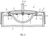
- FIG. 3 shows a further embodiment of a lamp 1 according to the invention in the form of a pendant lamp.
- the outer region 7 of the lampshade is cylindrical.
- the lampshade is externally enclosed in part by a hollow cylindrical aperture 12 made of metal.
- the lampshade itself is therefore visible from the outside only in the area of the light exit end. If you look from the top of the lampshade, also an annular area 15 between the support plate 9 and aperture 12 is visible. Through this annular region 15, part of the light is radiated upward.
- the light source serve in this case a plurality of LEDs 6. These are arranged uniformly around the axis 13 of the lampshade around. In this embodiment as well, the LEDs are held by a carrier plate 9 embedded in the lampshade. Between the support plate 9 and the stepped portion 8 of the lampshade, on which the support plate rests, a seal 14 is provided to prevent the ingress of dirt into the dome-shaped indentation 5 of the lampshade.
- the height of the indentation is about 60% of the height of the lampshade.
- the width of the indentation is about 50% of the width of the lampshade.
Landscapes
- Engineering & Computer Science (AREA)
- General Engineering & Computer Science (AREA)
- Physics & Mathematics (AREA)
- Microelectronics & Electronic Packaging (AREA)
- Optics & Photonics (AREA)
- Non-Portable Lighting Devices Or Systems Thereof (AREA)
Claims (14)
- Abat-jour transparent (2) pour une lampe (1) comportant une source lumineuse (6) sous la forme d'au moins une LED, l'abat-jour (2) présentant une extrémité d'entrée de lumière fermée (3), la source lumineuse (6) pouvant être disposée à l'extérieur de l'abat-jour (2) sur le côté extérieur de l'abat-jour (2) et l'abat-jour (2) présentant une partie (5) en retrait vers l'intérieur, qui est formée sur l'intérieur et l'extérieur, dirigée vers la sortie de lumière (4) caractérisé en ce que l'abat-jour (2) présente une extrémité de sortie de lumière ouverte avec une ouverture de sortie de lumière (4), et une zone de transition sensiblement étagée (8) est formée entre la partie (5) en retrait vers l'intérieur et une zone extérieure (7) de l'abat-jour (2) adjacente à la partie (5) en retrait vers l'intérieur.
- Abat-jour (2) selon la revendication 1, caractérisé en ce que la hauteur (C) de la partie (5) en retrait vers l'intérieur correspond à au moins 50% de la hauteur (D) de l'abat-jour (2).
- Abat-jour (2) selon la revendication 1, caractérisé en ce que la hauteur (C) de la partie (5) en retrait vers l'intérieur correspond à au moins 70%, de préférence au moins 80% de la hauteur (D) de l'abat-jour (2).
- Abat-jour (2) selon l'une des revendications 1 à 3, caractérisé en ce que la largeur (A) de la partie (5) en retrait vers l'intérieur correspond à au moins 25%, de préférence au moins 40% de la largeur (D) de l'abat-jour (2).
- Abat-jour (2) selon l'une des revendications 1 à 4, caractérisé en ce que la partie (5) en retrait vers l'intérieur se présente essentiellement sous forme de calotte sphérique ou de dôme.
- Abat-jour (2) selon l'une des revendications 1 à 5, caractérisé en ce que la zone extérieure (7) de l'abat-jour (2) est sensiblement toroïdale ou cylindrique.
- Abat-jour (2) selon l'une des revendications 1 à 6, caractérisé en ce que l'abat-jour (2) est réalisé en une seule pièce.
- Abat-jour (2) selon l'une des revendications 1 à 7, caractérisé en ce que la surface de l'abat-jour (2) est mate au moins dans la zone de la partie (5) en retrait vers l'intérieur.
- Abat-jour (2) selon l'une des revendications 1 à 8, caractérisé en ce que la surface de l'abat-jour (2) présente une structure de surface définie, en particulier une structure rainurée, en nid d'abeille ou pyramidale, au moins dans la zone de la partie en retrait (5) vers l'intérieur.
- Lampe (1) comportant une source lumineuse (6) sous la forme d'au moins une LED, caractérisée en ce que la lampe présente un abat-jour transparent (2) selon l'une des revendications 1 à 9, la source lumineuse (6) étant disposée à l'extrémité d'entrée de lumière (3) à l'extérieur de l'abat-jour (2).
- Lampe (1) selon la revendication 10, caractérisée en ce que la lampe comprend une plaque support (9) sur laquelle est disposée la LED (6).
- Lampe (1) selon la revendication 11, caractérisée en ce que la plaque support (9) est intégrée dans l'abat-jour (2).
- Lampe (1) selon l'une des revendications 10 à 12, caractérisée en ce que la plaque support (9) et l'extérieur de l'abat-jour (2) sont à fleur avec la surface.
- Lampe (1) selon l'une des revendications 10 à 13, caractérisée en ce que l'abat-jour (2) est vissé sur la plaque support (9).
Priority Applications (2)
| Application Number | Priority Date | Filing Date | Title |
|---|---|---|---|
| EP13004636.0A EP2851612B1 (fr) | 2013-09-24 | 2013-09-24 | Lampe dotée d'un abat-jour |
| US14/494,494 US9328893B2 (en) | 2013-09-24 | 2014-09-23 | Luminaire with a lampshade |
Applications Claiming Priority (1)
| Application Number | Priority Date | Filing Date | Title |
|---|---|---|---|
| EP13004636.0A EP2851612B1 (fr) | 2013-09-24 | 2013-09-24 | Lampe dotée d'un abat-jour |
Publications (2)
| Publication Number | Publication Date |
|---|---|
| EP2851612A1 EP2851612A1 (fr) | 2015-03-25 |
| EP2851612B1 true EP2851612B1 (fr) | 2019-06-26 |
Family
ID=49253068
Family Applications (1)
| Application Number | Title | Priority Date | Filing Date |
|---|---|---|---|
| EP13004636.0A Active EP2851612B1 (fr) | 2013-09-24 | 2013-09-24 | Lampe dotée d'un abat-jour |
Country Status (2)
| Country | Link |
|---|---|
| US (1) | US9328893B2 (fr) |
| EP (1) | EP2851612B1 (fr) |
Families Citing this family (4)
| Publication number | Priority date | Publication date | Assignee | Title |
|---|---|---|---|---|
| US10393341B2 (en) | 2015-04-24 | 2019-08-27 | Abl Ip Holding Llc | Tri-lobe optic and associated light fixtures |
| USD779112S1 (en) * | 2015-04-24 | 2017-02-14 | Abl Ip Holding Llc | Tri-lobe light fixture optic |
| DE202016102486U1 (de) | 2016-03-24 | 2016-06-20 | Thomas Simmerlein | Leuchtenschirm |
| CN107013850B (zh) * | 2017-06-07 | 2019-02-12 | 中山市华凌照明有限公司 | 一种便于安装的led挂灯 |
Family Cites Families (32)
| Publication number | Priority date | Publication date | Assignee | Title |
|---|---|---|---|---|
| US20030223238A1 (en) * | 2002-06-04 | 2003-12-04 | Yuan-Shun Hsu | Foaming molded lampshade |
| US6903380B2 (en) * | 2003-04-11 | 2005-06-07 | Weldon Technologies, Inc. | High power light emitting diode |
| US20130293098A1 (en) * | 2006-08-03 | 2013-11-07 | Intematix Corporation | Solid-state linear lighting arrangements including light emitting phosphor |
| US7686478B1 (en) * | 2007-01-12 | 2010-03-30 | Ilight Technologies, Inc. | Bulb for light-emitting diode with color-converting insert |
| US7663315B1 (en) * | 2007-07-24 | 2010-02-16 | Ilight Technologies, Inc. | Spherical bulb for light-emitting diode with spherical inner cavity |
| US7967477B2 (en) * | 2007-09-06 | 2011-06-28 | Philips Lumileds Lighting Company Llc | Compact optical system and lenses for producing uniform collimated light |
| US9551477B2 (en) * | 2011-11-15 | 2017-01-24 | Tseng-Lu Chien | More than one level(s) LED bulb has multiple features |
| US8434883B2 (en) * | 2009-05-11 | 2013-05-07 | SemiOptoelectronics Co., Ltd. | LLB bulb having light extracting rough surface pattern (LERSP) and method of fabrication |
| CN101936501B (zh) * | 2009-06-30 | 2013-04-24 | 富准精密工业(深圳)有限公司 | 发光二极管模组 |
| USD628740S1 (en) * | 2009-07-02 | 2010-12-07 | Bocci Design & Manufacturing Inc. | Blown glass pendant for decorative light fixtures |
| CN101949494A (zh) * | 2009-07-10 | 2011-01-19 | 富准精密工业(深圳)有限公司 | 发光组件 |
| US8348482B1 (en) * | 2009-12-24 | 2013-01-08 | Bocci Design & Manufacturing, Inc. | Pendant light |
| WO2012029711A1 (fr) * | 2010-08-31 | 2012-03-08 | 東芝ライテック株式会社 | Lentille, système d'éclairage, lampe en forme d'ampoule et appareil d'éclairage |
| JP5668251B2 (ja) * | 2010-08-31 | 2015-02-12 | 東芝ライテック株式会社 | 電球形ランプおよび照明器具 |
| KR20130139938A (ko) * | 2010-10-05 | 2013-12-23 | 인터매틱스 코포레이션 | 포토루미네센스 파장 변환을 구비한 고체상태 발광 디바이스 및 표지판 |
| US8297799B2 (en) * | 2010-12-02 | 2012-10-30 | Aether Systems Inc. | Omnidirectional LED lamp and complex, unitary lens |
| US8496349B2 (en) * | 2011-01-04 | 2013-07-30 | Unity Opto Technology Co., Ltd. | Uniform light emitting lamp structure |
| JP6023168B2 (ja) * | 2011-04-01 | 2016-11-09 | フィリップス ライティング ホールディング ビー ヴィ | 光源、ランプ、および光源を製造するための方法 |
| US8419233B2 (en) * | 2011-05-10 | 2013-04-16 | Applied Lighting Company | Lampshade structure for LED lamps |
| US20130010464A1 (en) * | 2011-07-07 | 2013-01-10 | BritePointe, Inc. | High intensity lighting fixture |
| TWI412706B (zh) * | 2011-07-27 | 2013-10-21 | 麗光科技股份有限公司 | 光源模組 |
| CN104011461B (zh) * | 2011-12-20 | 2017-05-24 | 纳卢克斯株式会社 | 光学元件、包含该光学元件的照明装置以及使用了该照明装置的照明模块 |
| TWI454631B (zh) * | 2011-12-29 | 2014-10-01 | Univ Nat Kaohsiung Applied Sci | Adjustable variable light emitting diode lens and lamp with its own |
| DE202012101697U1 (de) | 2012-05-09 | 2012-05-24 | Chien-Chi Tseng | Lampenschirm |
| CN202647579U (zh) * | 2012-05-24 | 2013-01-02 | 成都凯裕电子电器有限公司 | 自发光水母灯 |
| JPWO2014020848A1 (ja) * | 2012-08-02 | 2016-07-21 | 株式会社小糸製作所 | 樹脂製光学部材および車両用灯具 |
| CN104508366A (zh) * | 2012-08-09 | 2015-04-08 | 普司科Led股份有限公司 | Led照明装置 |
| US10436969B2 (en) * | 2013-01-30 | 2019-10-08 | Ideal Industries Lighting Llc | Optical waveguide and luminaire incorporating same |
| JP6200654B2 (ja) * | 2013-02-15 | 2017-09-20 | 東芝ライテック株式会社 | 発光モジュール、発光装置および照明装置 |
| US10379278B2 (en) * | 2013-03-15 | 2019-08-13 | Ideal Industries Lighting Llc | Outdoor and/or enclosed structure LED luminaire outdoor and/or enclosed structure LED luminaire having outward illumination |
| USD695442S1 (en) * | 2013-04-22 | 2013-12-10 | Quarkstar Llc | Ceiling tile with luminaire |
| US9303864B2 (en) * | 2014-09-01 | 2016-04-05 | Teng-Chia Yen | LED light for ceiling fan |
-
2013
- 2013-09-24 EP EP13004636.0A patent/EP2851612B1/fr active Active
-
2014
- 2014-09-23 US US14/494,494 patent/US9328893B2/en active Active
Non-Patent Citations (1)
| Title |
|---|
| None * |
Also Published As
| Publication number | Publication date |
|---|---|
| US9328893B2 (en) | 2016-05-03 |
| EP2851612A1 (fr) | 2015-03-25 |
| US20150085483A1 (en) | 2015-03-26 |
Similar Documents
| Publication | Publication Date | Title |
|---|---|---|
| EP2207996B1 (fr) | Lampe led à diffuseur | |
| EP2884155B1 (fr) | Éclairage avec guide de lumière | |
| EP1697683B1 (fr) | Lampe encastree | |
| EP2851612B1 (fr) | Lampe dotée d'un abat-jour | |
| DE102010014839B4 (de) | Einbauleuchte | |
| DE202010006557U1 (de) | Einbauleuchte | |
| DE202016104062U1 (de) | Anordnung zur Lichtabgabe | |
| EP3045803B1 (fr) | Éclairage | |
| EP3473916B1 (fr) | Luminaire pourvu d'unité d'éclairage ainsi qu'une couverture entourant l'unité d'éclairage | |
| EP3034928B1 (fr) | Éclairage et moyen d'eclairage associe | |
| EP2902699A1 (fr) | Unité d'éclairage pour des éclairages en forme de lanterne | |
| EP2518388B1 (fr) | Eclairage | |
| CH702227B1 (de) | Leuchte mit gläsernem Schirm. | |
| DE8515067U1 (de) | An oder in einer Decke oder Wand anzubringende Ein- oder Anbauleuchte | |
| EP2994690B1 (fr) | Luminaire équipé d'un boîtier comportant plusieurs orifices de rayonnement de lumière | |
| EP0930459A2 (fr) | Réflecteur pour une source lumineuse, notamment pour éclairage d' ambiance | |
| DE102004042821A1 (de) | Strahler | |
| EP4384750A1 (fr) | Lampe encastrée, en particulier plafonnier encastré | |
| DE202014105686U1 (de) | Fahrzeuglampe | |
| DE202014102021U1 (de) | Optisches Element für eine Lichtquelle einer Leuchte, sowie Leuchte | |
| DE202010004646U1 (de) | Leuchte, insbesondere Verkaufsraumbeleuchtung | |
| EP1521032A1 (fr) | Luminaire | |
| DE102015105505A1 (de) | Multifunktionale lichttechnische Abdeckung mit Direktlichtbereich | |
| DE29915122U1 (de) | Leuchte | |
| DE202013010472U1 (de) | Aufhängung für Strahler mit Beleuchtungszweck |
Legal Events
| Date | Code | Title | Description |
|---|---|---|---|
| PUAI | Public reference made under article 153(3) epc to a published international application that has entered the european phase |
Free format text: ORIGINAL CODE: 0009012 |
|
| 17P | Request for examination filed |
Effective date: 20140826 |
|
| AK | Designated contracting states |
Kind code of ref document: A1 Designated state(s): AL AT BE BG CH CY CZ DE DK EE ES FI FR GB GR HR HU IE IS IT LI LT LU LV MC MK MT NL NO PL PT RO RS SE SI SK SM TR |
|
| AX | Request for extension of the european patent |
Extension state: BA ME |
|
| RIC1 | Information provided on ipc code assigned before grant |
Ipc: F21V 3/00 20150101ALI20181130BHEP Ipc: F21S 8/06 20060101ALI20181130BHEP Ipc: F21V 1/14 20060101ALI20181130BHEP Ipc: F21Y 115/10 20160101ALI20181130BHEP Ipc: F21V 1/00 20060101AFI20181130BHEP |
|
| GRAP | Despatch of communication of intention to grant a patent |
Free format text: ORIGINAL CODE: EPIDOSNIGR1 |
|
| STAA | Information on the status of an ep patent application or granted ep patent |
Free format text: STATUS: GRANT OF PATENT IS INTENDED |
|
| INTG | Intention to grant announced |
Effective date: 20190206 |
|
| GRAS | Grant fee paid |
Free format text: ORIGINAL CODE: EPIDOSNIGR3 |
|
| GRAA | (expected) grant |
Free format text: ORIGINAL CODE: 0009210 |
|
| STAA | Information on the status of an ep patent application or granted ep patent |
Free format text: STATUS: THE PATENT HAS BEEN GRANTED |
|
| AK | Designated contracting states |
Kind code of ref document: B1 Designated state(s): AL AT BE BG CH CY CZ DE DK EE ES FI FR GB GR HR HU IE IS IT LI LT LU LV MC MK MT NL NO PL PT RO RS SE SI SK SM TR |
|
| REG | Reference to a national code |
Ref country code: GB Ref legal event code: FG4D Free format text: NOT ENGLISH |
|
| REG | Reference to a national code |
Ref country code: CH Ref legal event code: EP |
|
| REG | Reference to a national code |
Ref country code: AT Ref legal event code: REF Ref document number: 1148710 Country of ref document: AT Kind code of ref document: T Effective date: 20190715 |
|
| REG | Reference to a national code |
Ref country code: DE Ref legal event code: R096 Ref document number: 502013013044 Country of ref document: DE |
|
| REG | Reference to a national code |
Ref country code: IE Ref legal event code: FG4D Free format text: LANGUAGE OF EP DOCUMENT: GERMAN |
|
| REG | Reference to a national code |
Ref country code: NL Ref legal event code: MP Effective date: 20190626 |
|
| PG25 | Lapsed in a contracting state [announced via postgrant information from national office to epo] |
Ref country code: FI Free format text: LAPSE BECAUSE OF FAILURE TO SUBMIT A TRANSLATION OF THE DESCRIPTION OR TO PAY THE FEE WITHIN THE PRESCRIBED TIME-LIMIT Effective date: 20190626 Ref country code: AL Free format text: LAPSE BECAUSE OF FAILURE TO SUBMIT A TRANSLATION OF THE DESCRIPTION OR TO PAY THE FEE WITHIN THE PRESCRIBED TIME-LIMIT Effective date: 20190626 Ref country code: NO Free format text: LAPSE BECAUSE OF FAILURE TO SUBMIT A TRANSLATION OF THE DESCRIPTION OR TO PAY THE FEE WITHIN THE PRESCRIBED TIME-LIMIT Effective date: 20190926 Ref country code: SE Free format text: LAPSE BECAUSE OF FAILURE TO SUBMIT A TRANSLATION OF THE DESCRIPTION OR TO PAY THE FEE WITHIN THE PRESCRIBED TIME-LIMIT Effective date: 20190626 Ref country code: LT Free format text: LAPSE BECAUSE OF FAILURE TO SUBMIT A TRANSLATION OF THE DESCRIPTION OR TO PAY THE FEE WITHIN THE PRESCRIBED TIME-LIMIT Effective date: 20190626 Ref country code: HR Free format text: LAPSE BECAUSE OF FAILURE TO SUBMIT A TRANSLATION OF THE DESCRIPTION OR TO PAY THE FEE WITHIN THE PRESCRIBED TIME-LIMIT Effective date: 20190626 |
|
| REG | Reference to a national code |
Ref country code: LT Ref legal event code: MG4D |
|
| PG25 | Lapsed in a contracting state [announced via postgrant information from national office to epo] |
Ref country code: LV Free format text: LAPSE BECAUSE OF FAILURE TO SUBMIT A TRANSLATION OF THE DESCRIPTION OR TO PAY THE FEE WITHIN THE PRESCRIBED TIME-LIMIT Effective date: 20190626 Ref country code: RS Free format text: LAPSE BECAUSE OF FAILURE TO SUBMIT A TRANSLATION OF THE DESCRIPTION OR TO PAY THE FEE WITHIN THE PRESCRIBED TIME-LIMIT Effective date: 20190626 Ref country code: BG Free format text: LAPSE BECAUSE OF FAILURE TO SUBMIT A TRANSLATION OF THE DESCRIPTION OR TO PAY THE FEE WITHIN THE PRESCRIBED TIME-LIMIT Effective date: 20190926 Ref country code: GR Free format text: LAPSE BECAUSE OF FAILURE TO SUBMIT A TRANSLATION OF THE DESCRIPTION OR TO PAY THE FEE WITHIN THE PRESCRIBED TIME-LIMIT Effective date: 20190927 |
|
| PG25 | Lapsed in a contracting state [announced via postgrant information from national office to epo] |
Ref country code: PT Free format text: LAPSE BECAUSE OF FAILURE TO SUBMIT A TRANSLATION OF THE DESCRIPTION OR TO PAY THE FEE WITHIN THE PRESCRIBED TIME-LIMIT Effective date: 20191028 Ref country code: EE Free format text: LAPSE BECAUSE OF FAILURE TO SUBMIT A TRANSLATION OF THE DESCRIPTION OR TO PAY THE FEE WITHIN THE PRESCRIBED TIME-LIMIT Effective date: 20190626 Ref country code: SK Free format text: LAPSE BECAUSE OF FAILURE TO SUBMIT A TRANSLATION OF THE DESCRIPTION OR TO PAY THE FEE WITHIN THE PRESCRIBED TIME-LIMIT Effective date: 20190626 Ref country code: RO Free format text: LAPSE BECAUSE OF FAILURE TO SUBMIT A TRANSLATION OF THE DESCRIPTION OR TO PAY THE FEE WITHIN THE PRESCRIBED TIME-LIMIT Effective date: 20190626 Ref country code: CZ Free format text: LAPSE BECAUSE OF FAILURE TO SUBMIT A TRANSLATION OF THE DESCRIPTION OR TO PAY THE FEE WITHIN THE PRESCRIBED TIME-LIMIT Effective date: 20190626 Ref country code: NL Free format text: LAPSE BECAUSE OF FAILURE TO SUBMIT A TRANSLATION OF THE DESCRIPTION OR TO PAY THE FEE WITHIN THE PRESCRIBED TIME-LIMIT Effective date: 20190626 |
|
| PG25 | Lapsed in a contracting state [announced via postgrant information from national office to epo] |
Ref country code: ES Free format text: LAPSE BECAUSE OF FAILURE TO SUBMIT A TRANSLATION OF THE DESCRIPTION OR TO PAY THE FEE WITHIN THE PRESCRIBED TIME-LIMIT Effective date: 20190626 Ref country code: SM Free format text: LAPSE BECAUSE OF FAILURE TO SUBMIT A TRANSLATION OF THE DESCRIPTION OR TO PAY THE FEE WITHIN THE PRESCRIBED TIME-LIMIT Effective date: 20190626 Ref country code: IS Free format text: LAPSE BECAUSE OF FAILURE TO SUBMIT A TRANSLATION OF THE DESCRIPTION OR TO PAY THE FEE WITHIN THE PRESCRIBED TIME-LIMIT Effective date: 20191026 |
|
| PG25 | Lapsed in a contracting state [announced via postgrant information from national office to epo] |
Ref country code: TR Free format text: LAPSE BECAUSE OF FAILURE TO SUBMIT A TRANSLATION OF THE DESCRIPTION OR TO PAY THE FEE WITHIN THE PRESCRIBED TIME-LIMIT Effective date: 20190626 |
|
| PG25 | Lapsed in a contracting state [announced via postgrant information from national office to epo] |
Ref country code: PL Free format text: LAPSE BECAUSE OF FAILURE TO SUBMIT A TRANSLATION OF THE DESCRIPTION OR TO PAY THE FEE WITHIN THE PRESCRIBED TIME-LIMIT Effective date: 20190626 Ref country code: DK Free format text: LAPSE BECAUSE OF FAILURE TO SUBMIT A TRANSLATION OF THE DESCRIPTION OR TO PAY THE FEE WITHIN THE PRESCRIBED TIME-LIMIT Effective date: 20190626 |
|
| PG25 | Lapsed in a contracting state [announced via postgrant information from national office to epo] |
Ref country code: IS Free format text: LAPSE BECAUSE OF FAILURE TO SUBMIT A TRANSLATION OF THE DESCRIPTION OR TO PAY THE FEE WITHIN THE PRESCRIBED TIME-LIMIT Effective date: 20200224 Ref country code: MC Free format text: LAPSE BECAUSE OF FAILURE TO SUBMIT A TRANSLATION OF THE DESCRIPTION OR TO PAY THE FEE WITHIN THE PRESCRIBED TIME-LIMIT Effective date: 20190626 |
|
| REG | Reference to a national code |
Ref country code: CH Ref legal event code: PL |
|
| REG | Reference to a national code |
Ref country code: DE Ref legal event code: R097 Ref document number: 502013013044 Country of ref document: DE |
|
| PLBE | No opposition filed within time limit |
Free format text: ORIGINAL CODE: 0009261 |
|
| STAA | Information on the status of an ep patent application or granted ep patent |
Free format text: STATUS: NO OPPOSITION FILED WITHIN TIME LIMIT |
|
| PG2D | Information on lapse in contracting state deleted |
Ref country code: IS |
|
| PG25 | Lapsed in a contracting state [announced via postgrant information from national office to epo] |
Ref country code: CH Free format text: LAPSE BECAUSE OF NON-PAYMENT OF DUE FEES Effective date: 20190930 Ref country code: LU Free format text: LAPSE BECAUSE OF NON-PAYMENT OF DUE FEES Effective date: 20190924 Ref country code: LI Free format text: LAPSE BECAUSE OF NON-PAYMENT OF DUE FEES Effective date: 20190930 Ref country code: IE Free format text: LAPSE BECAUSE OF NON-PAYMENT OF DUE FEES Effective date: 20190924 |
|
| REG | Reference to a national code |
Ref country code: BE Ref legal event code: MM Effective date: 20190930 |
|
| 26N | No opposition filed |
Effective date: 20200603 |
|
| PG25 | Lapsed in a contracting state [announced via postgrant information from national office to epo] |
Ref country code: SI Free format text: LAPSE BECAUSE OF FAILURE TO SUBMIT A TRANSLATION OF THE DESCRIPTION OR TO PAY THE FEE WITHIN THE PRESCRIBED TIME-LIMIT Effective date: 20190626 Ref country code: BE Free format text: LAPSE BECAUSE OF NON-PAYMENT OF DUE FEES Effective date: 20190930 |
|
| PG25 | Lapsed in a contracting state [announced via postgrant information from national office to epo] |
Ref country code: CY Free format text: LAPSE BECAUSE OF FAILURE TO SUBMIT A TRANSLATION OF THE DESCRIPTION OR TO PAY THE FEE WITHIN THE PRESCRIBED TIME-LIMIT Effective date: 20190626 |
|
| PG25 | Lapsed in a contracting state [announced via postgrant information from national office to epo] |
Ref country code: MT Free format text: LAPSE BECAUSE OF FAILURE TO SUBMIT A TRANSLATION OF THE DESCRIPTION OR TO PAY THE FEE WITHIN THE PRESCRIBED TIME-LIMIT Effective date: 20190626 Ref country code: HU Free format text: LAPSE BECAUSE OF FAILURE TO SUBMIT A TRANSLATION OF THE DESCRIPTION OR TO PAY THE FEE WITHIN THE PRESCRIBED TIME-LIMIT; INVALID AB INITIO Effective date: 20130924 |
|
| PG25 | Lapsed in a contracting state [announced via postgrant information from national office to epo] |
Ref country code: MK Free format text: LAPSE BECAUSE OF FAILURE TO SUBMIT A TRANSLATION OF THE DESCRIPTION OR TO PAY THE FEE WITHIN THE PRESCRIBED TIME-LIMIT Effective date: 20190626 |
|
| PGFP | Annual fee paid to national office [announced via postgrant information from national office to epo] |
Ref country code: DE Payment date: 20250923 Year of fee payment: 13 |
|
| PGFP | Annual fee paid to national office [announced via postgrant information from national office to epo] |
Ref country code: IT Payment date: 20250929 Year of fee payment: 13 |
|
| PGFP | Annual fee paid to national office [announced via postgrant information from national office to epo] |
Ref country code: GB Payment date: 20250927 Year of fee payment: 13 |
|
| PGFP | Annual fee paid to national office [announced via postgrant information from national office to epo] |
Ref country code: AT Payment date: 20250923 Year of fee payment: 13 Ref country code: FR Payment date: 20250926 Year of fee payment: 13 |
|
| REG | Reference to a national code |
Ref country code: DE Ref legal event code: R082 Ref document number: 502013013044 Country of ref document: DE Representative=s name: HABERMANN INTELLECTUAL PROPERTY PARTNERSCHAFT , DE |