EP2851630B1 - Générateur photovoltaïque du type à poursuite - Google Patents
Générateur photovoltaïque du type à poursuite Download PDFInfo
- Publication number
- EP2851630B1 EP2851630B1 EP13791564.1A EP13791564A EP2851630B1 EP 2851630 B1 EP2851630 B1 EP 2851630B1 EP 13791564 A EP13791564 A EP 13791564A EP 2851630 B1 EP2851630 B1 EP 2851630B1
- Authority
- EP
- European Patent Office
- Prior art keywords
- rotating
- connection bar
- photovoltaic generator
- turning
- coupling
- Prior art date
- Legal status (The legal status is an assumption and is not a legal conclusion. Google has not performed a legal analysis and makes no representation as to the accuracy of the status listed.)
- Active
Links
Images





Classifications
-
- H—ELECTRICITY
- H10—SEMICONDUCTOR DEVICES; ELECTRIC SOLID-STATE DEVICES NOT OTHERWISE PROVIDED FOR
- H10F—INORGANIC SEMICONDUCTOR DEVICES SENSITIVE TO INFRARED RADIATION, LIGHT, ELECTROMAGNETIC RADIATION OF SHORTER WAVELENGTH OR CORPUSCULAR RADIATION
- H10F19/00—Integrated devices, or assemblies of multiple devices, comprising at least one photovoltaic cell covered by group H10F10/00, e.g. photovoltaic modules
-
- H—ELECTRICITY
- H02—GENERATION; CONVERSION OR DISTRIBUTION OF ELECTRIC POWER
- H02S—GENERATION OF ELECTRIC POWER BY CONVERSION OF INFRARED RADIATION, VISIBLE LIGHT OR ULTRAVIOLET LIGHT, e.g. USING PHOTOVOLTAIC [PV] MODULES
- H02S20/00—Supporting structures for PV modules
- H02S20/30—Supporting structures being movable or adjustable, e.g. for angle adjustment
- H02S20/32—Supporting structures being movable or adjustable, e.g. for angle adjustment specially adapted for solar tracking
-
- F—MECHANICAL ENGINEERING; LIGHTING; HEATING; WEAPONS; BLASTING
- F24—HEATING; RANGES; VENTILATING
- F24S—SOLAR HEAT COLLECTORS; SOLAR HEAT SYSTEMS
- F24S30/00—Arrangements for moving or orienting solar heat collector modules
- F24S30/40—Arrangements for moving or orienting solar heat collector modules for rotary movement
- F24S30/42—Arrangements for moving or orienting solar heat collector modules for rotary movement with only one rotation axis
- F24S30/425—Horizontal axis
-
- F—MECHANICAL ENGINEERING; LIGHTING; HEATING; WEAPONS; BLASTING
- F24—HEATING; RANGES; VENTILATING
- F24S—SOLAR HEAT COLLECTORS; SOLAR HEAT SYSTEMS
- F24S50/00—Arrangements for controlling solar heat collectors
- F24S50/20—Arrangements for controlling solar heat collectors for tracking
-
- F—MECHANICAL ENGINEERING; LIGHTING; HEATING; WEAPONS; BLASTING
- F24—HEATING; RANGES; VENTILATING
- F24S—SOLAR HEAT COLLECTORS; SOLAR HEAT SYSTEMS
- F24S30/00—Arrangements for moving or orienting solar heat collector modules
- F24S2030/10—Special components
- F24S2030/13—Transmissions
- F24S2030/131—Transmissions in the form of articulated bars
-
- F—MECHANICAL ENGINEERING; LIGHTING; HEATING; WEAPONS; BLASTING
- F24—HEATING; RANGES; VENTILATING
- F24S—SOLAR HEAT COLLECTORS; SOLAR HEAT SYSTEMS
- F24S30/00—Arrangements for moving or orienting solar heat collector modules
- F24S2030/10—Special components
- F24S2030/13—Transmissions
- F24S2030/136—Transmissions for moving several solar collectors by common transmission elements
-
- F—MECHANICAL ENGINEERING; LIGHTING; HEATING; WEAPONS; BLASTING
- F24—HEATING; RANGES; VENTILATING
- F24S—SOLAR HEAT COLLECTORS; SOLAR HEAT SYSTEMS
- F24S30/00—Arrangements for moving or orienting solar heat collector modules
- F24S2030/10—Special components
- F24S2030/14—Movement guiding means
-
- F—MECHANICAL ENGINEERING; LIGHTING; HEATING; WEAPONS; BLASTING
- F24—HEATING; RANGES; VENTILATING
- F24S—SOLAR HEAT COLLECTORS; SOLAR HEAT SYSTEMS
- F24S30/00—Arrangements for moving or orienting solar heat collector modules
- F24S2030/10—Special components
- F24S2030/15—Bearings
-
- F—MECHANICAL ENGINEERING; LIGHTING; HEATING; WEAPONS; BLASTING
- F24—HEATING; RANGES; VENTILATING
- F24S—SOLAR HEAT COLLECTORS; SOLAR HEAT SYSTEMS
- F24S25/00—Arrangement of stationary mountings or supports for solar heat collector modules
- F24S25/10—Arrangement of stationary mountings or supports for solar heat collector modules extending in directions away from a supporting surface
-
- F—MECHANICAL ENGINEERING; LIGHTING; HEATING; WEAPONS; BLASTING
- F24—HEATING; RANGES; VENTILATING
- F24S—SOLAR HEAT COLLECTORS; SOLAR HEAT SYSTEMS
- F24S25/00—Arrangement of stationary mountings or supports for solar heat collector modules
- F24S25/50—Arrangement of stationary mountings or supports for solar heat collector modules comprising elongate non-rigid elements, e.g. straps, wires or ropes
-
- F—MECHANICAL ENGINEERING; LIGHTING; HEATING; WEAPONS; BLASTING
- F24—HEATING; RANGES; VENTILATING
- F24S—SOLAR HEAT COLLECTORS; SOLAR HEAT SYSTEMS
- F24S30/00—Arrangements for moving or orienting solar heat collector modules
- F24S30/40—Arrangements for moving or orienting solar heat collector modules for rotary movement
- F24S30/42—Arrangements for moving or orienting solar heat collector modules for rotary movement with only one rotation axis
-
- Y—GENERAL TAGGING OF NEW TECHNOLOGICAL DEVELOPMENTS; GENERAL TAGGING OF CROSS-SECTIONAL TECHNOLOGIES SPANNING OVER SEVERAL SECTIONS OF THE IPC; TECHNICAL SUBJECTS COVERED BY FORMER USPC CROSS-REFERENCE ART COLLECTIONS [XRACs] AND DIGESTS
- Y02—TECHNOLOGIES OR APPLICATIONS FOR MITIGATION OR ADAPTATION AGAINST CLIMATE CHANGE
- Y02E—REDUCTION OF GREENHOUSE GAS [GHG] EMISSIONS, RELATED TO ENERGY GENERATION, TRANSMISSION OR DISTRIBUTION
- Y02E10/00—Energy generation through renewable energy sources
- Y02E10/40—Solar thermal energy, e.g. solar towers
- Y02E10/47—Mountings or tracking
-
- Y—GENERAL TAGGING OF NEW TECHNOLOGICAL DEVELOPMENTS; GENERAL TAGGING OF CROSS-SECTIONAL TECHNOLOGIES SPANNING OVER SEVERAL SECTIONS OF THE IPC; TECHNICAL SUBJECTS COVERED BY FORMER USPC CROSS-REFERENCE ART COLLECTIONS [XRACs] AND DIGESTS
- Y02—TECHNOLOGIES OR APPLICATIONS FOR MITIGATION OR ADAPTATION AGAINST CLIMATE CHANGE
- Y02E—REDUCTION OF GREENHOUSE GAS [GHG] EMISSIONS, RELATED TO ENERGY GENERATION, TRANSMISSION OR DISTRIBUTION
- Y02E10/00—Energy generation through renewable energy sources
- Y02E10/50—Photovoltaic [PV] energy
Definitions
- the present invention relates, in general, to tracking photovoltaic generators and, more particularly, to a tracking photovoltaic generator in which a plurality of solar modules are arranged in one or more rows to form groups of solar modules, and the groups of arranged solar modules can be rotated according to the location of the sun by operation of a linear actuator.
- a plurality of posts for supporting solar modules are installed upright on the ground.
- a single rotating shaft is provided.
- the solar modules are integrally supported on an upper end of the rotating shaft.
- one or more solar modules are provided in the form of a group; although the number of solar modules is determined depending on a required amount of electricity.
- a device for varying the orientation of a large, medium or small-sized group of solar modules according to the location of the sun is required.
- a conventional tracking photovoltaic generator to vary the orientation of solar modules according to the time-based location of the sun, motors for operating rotating shafts of the solar modules are provided for the respective solar modules.
- the controller controls tracking of the solar modules in each group in a centrally controlled manner.
- a tracking photovoltaic generator In a tracking photovoltaic generator according to the present invention, a plurality of solar modules are arranged in one or more rows to form one or more groups of solar modules, and the arranged solar modules are rotated by operation of a linear actuator according to the location of the sun.
- the multiple groups of solar modules can be rotated or stopped at the same time by a simple method, whereby the production cost of the generator can be markedly reduced.
- the cell support may further include a diagonal frame extending upward from the vertical frame at a predetermined angle of inclination.
- the diagonal frame may be fixed to the lower surface of the turning shaft.
- connection bar may include first connection bars and second connection bars alternately connected to each other.
- the first and second connection bars have different diameters.
- connection bar may further include a rotating shaft provided in the connection bar and passing through opposite side surfaces of the connection bar, the rotating shaft rotatably coupling the turning bracket to the connection bar, and the turning bracket may be rotatably coupled at an end thereof to the connection bar by the rotating shaft disposed in a through hole corresponding to the shaft insert member.
- connection bar may further include a shaft insert member provided in the connection bar and configured to be closed at upper and lower sides by surfaces.
- the shaft insert member may extend to openings formed in the opposite side surfaces of the connection bar so that the rotating shaft is inserted into the shaft insert member.
- the tracking photovoltaic generator may further include one or more rotating units provided between the one or more cell supports and coupled to the corresponding turning shafts so that the turning shafts can be rotated.
- each of the rotating units may include: a rotator having an opening therein so that the turning shaft is inserted into the rotator, the rotator having an outer surface extending in opposite directions; gaskets seated on the outer surface of the rotator; a pair of rotating bearings disposed on opposite sides of the gaskets and seated on the outer surface of the rotator; coupling plates each having an opening therein so that the turning shaft passes through the coupling plates, the coupling plates being coupled to each other at opposite sides of the rotator based on the gaskets and the rotating bearings; and holding plates respectively coupled to front and rear portions of the coupling plates, each of the holding plates having in a central portion an opening corresponding to an outer shape of the turning shaft.
- each of the coupling plates may include: a plate body having a shape corresponding to the rotator and having an opening in a central portion thereof; a coupling part extending outward from the plate body, with one or more screw holes formed in the coupling part at positions spaced apart from each other; and one or more grooves formed in an outer surface of the plate body at positions corresponding to the respective screw holes.
- the coupling plate may further include a support part extending downward from the plate body.
- the support part may be fixed to an upper surface of the support post.
- the holding plate may be divided into a plurality of parts and fastened to a front surface of the coupling plate.
- the rotating unit may further include a fastening pin inserted into the holding plates coupled to the respective opposite sides of the rotator so that the holding plates are fastened to each other by the fastening pin.
- the rotator may have one or more coupling depressions formed in an outer surface of each of opposite sides of the rotating body having the opening therein.
- the coupling depressions form a stepped portion on which the corresponding gasket and bearing are seated.
- Fig. 1 is a plan view illustrating a tracking photovoltaic generator according to the present invention.
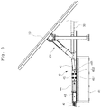
- Fig. 2 is a side view illustrating the tracking photovoltaic generator according to the present invention.
- the tracking photovoltaic generator includes a plurality of solar modules 10 that are arranged in longitudinal and lateral directions and are integrally rotated under the control of a control unit according to the location of the sun.
- the solar modules 10 are arranged in the lateral direction (for example, first to seventh rows) and in the longitudinal direction.
- the tracking photovoltaic generator further includes a drive unit 40 that comprises a linear actuator and generates drive force, a connection bar 30 that is connected to the drive unit 40, and cell supports (20, refer to Figs. 2 through 7 ) that supports the solar modules 10.
- a plurality of solar modules 10 that are arranged in the lateral direction forms a single group of solar modules.
- a plurality of groups of solar modules are arranged in the longitudinal direction.
- the groups of solar modules 10 are laterally connected to the single connection bar 30 that extends a predetermined length in the longitudinal direction. Therefore, the groups of solar modules 10 can be simultaneously rotated by the connection bar 30 that is moved forward or backward by the operation of the linear actuator of the drive unit 40.
- the corresponding solar modules 10 of the solar module groups are connected to the connection bar 30 by the cell supports 20. Therefore, when the connection bar 30 moves forward or backward, the solar modules 10 of the solar module groups are simultaneously rotated.
- the present invention is configured such that the connection bar 30 is linearly moved by the operation of the actuator of the drive unit 40 and the cell supports 20 that are connected to each other by the connection bar 30 are thus rotated forward or backward. Furthermore, each cell support 20 is connected to other cell supports 20 that are arranged in the lateral direction and configured so as to be rotatable. Hence, if rotating force resulting from the linear movement of the connection bar 30 is transmitted to one cell support 20, the other cell supports 20 that are connected to it in the lateral direction are rotated at the same time. As a result, the solar modules 10 supported on the cell supports 20 are simultaneously rotated.
- the tracking photovoltaic generator includes a sensor (not shown) for tracking the location of the sun, and the control unit (not shown) that controls the drive unit 40 in response to a sensing signal of the sensor. Therefore, these are not shown in the drawings and detailed description thereof will be omitted.
- the drive unit will be explained in detail with reference to Figs. 3 and 4 .
- the drive unit 40 includes a support table 41 that is placed on the ground and supports the actuator, a cylinder 42 that is provided on an upper surface of the support table 41 and generates linear drive force, a connection bracket 43 fixing the cylinder 42 in place, a bearing block 45 moving a linear direction, guide rails 44 that are provided on the upper surface of the support table 41 at positions spaced apart from each other and guide the bearing block 45 therebetween, and a link bar 46 coupled to the guide rails 44 so as to be rotatable upward or downward.
- the cylinder 42 is an electric-powered cylinder and generates force for driving the bearing block 45 and the link bar 46.
- connection bracket 43 is coupled to a front end of the cylinder 42 so that the cylinder 42 can be fixed to the upper surface of the support table 41.
- Each guide rail 44 spaced apart from each other, are provided in a pair.
- Each guide rail 44 includes horizontal plates 441 that are respectively provided on upper and lower ends of the guide rail and extend in the horizontal direction, a guide wall plate 444 forming a wall surface between the horizontal plates 441, and a support means 443 that protrudes a front end of the guide rail to support a side surface of the cylinder 42.
- the horizontal plates 441 respectively extend from the upper and lower ends of the guide wall plate 442 outward and toward the other guide rail 44. Particularly, extending outward, a portion of the lower horizontal plate 441 is brought into contact with the upper surface of the support table 41 and is fixed to the support table 41 by a fastening means 442 such as a screw.
- the support means 443 includes a support plate 443b that is oriented upright and extends from the front end of the guide rail 44 rearward, and a support rod 443a that extends from the support plate 443b, passes through the side surface of the guide rail 44, and is fixed to the guide rail 44.
- the support plate 443b Extending from the front end of the guide rail 44 rearward, the support plate 443b is disposed adjacent to the cylinder 42 and is supported by the support rod 443a.
- the support plate 443b is brought into close contact with the side surface of the cylinder 42 or is spaced apart therefrom by a predetermined distance such that the cylinder 42 can be reliably supported between the guide rails 44.
- the support rod 443a extends from the support plate 443b to the side surface of the guide rail 44, passes through the guide rail 44, and is fixed to the outer surface of the guide rail 44.
- the bearing block 45 includes four or more rotating rollers 451 that are provided on each of opposite side surfaces of the bearing block 45 and rotate along the corresponding guide wall plate 444, and a hinge shaft 452 coupled to the link bar 46.
- the four or more rotating rollers 451 are rotatably installed on each of the opposite surfaces of the bearing block 45.
- the rotating rollers 451 come into close contact with the inner surfaces of the horizontal plates 441 of the guide rails 44 and rotate along the horizontal plates 441 so that the bearing block 45 can move forward or backward.
- the hinge shaft 452 is a shaft laterally fixed in the bearing block 45.
- a front end of the link bar 46 is coupled to the hinge shaft 452 so as to be rotatable upward or downward.
- the coupling structure between the hinge shaft 452 and the link bar 46 is a well known hinge structure, and detailed description and illustration thereof will be omitted.
- the bearing block 45 moves along the guide rails 44 forward or backward. Therefore, the drive force of the cylinder 42 can be prevented from being undesirably converted from linear motion into rotational motion.
- One end of the link bar 46 is hinged to the bearing block 45, and the other end thereof is coupled to the connection bar 30.
- the cell support 20 is connected to a medial portion of the link bar 46.
- the link bar 46 transmits the force of the movement of the bearing block 45 to the connection bar 30, whereby the connection bar 30 is moved backwards.
- the link bar 46 is rotated upward by the linear movement force applied from the bearing block 45 and, as shown in Fig. 3 , is inclined upward with respect to the bearing block 45.
- the link bar 46 that has been inclined upward rotates around the hinge downward and positions itself parallel to the bearing block 45 while pulling the connection bar 30.
- connection bar 30 The reason for forming the above-mentioned construction is because it can absorb impact or vibrations generated on the connection bar 30 when force is applied from the cylinder 42 the connection bar 30 that has been in a stationary state.
- connection bar 30 and the cell support 20 will be explained with reference to Figs. 5 and 6 .
- connection bar 30 is configured to extend in one direction by coupling pipes having different diameters to each other.
- the connection bar 30 includes first connection bars 31 and second connection bars 32 each having a smaller diameter than that of the first connection bar 31.
- the first connection bar 31 and the second connection bar 32 are alternately connected to each other. Opposite ends of each second connection bar 32 are inserted into the corresponding first connection bars 31 and fixed thereto by a fastening means such as screws.
- a corresponding one of the second connection bars 32 is connected to the link bar 46 and the cell support 20. Extending in the lateral direction of the second connection bars 32, a shaft insert member 321 is provided in each of the second connection bars 32 that are connected to the respective cell supports 20. The rotating shaft 33, by which the cell support 20 is coupled to the second connection bar 32, is inserted into the shaft insert member 321.
- the shaft insert member 321 is a pipe extending in the lateral direction in the second connection bar 32.
- the shaft insert member 321 rotatably supports the rotating shaft 33.
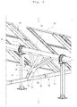
- the cell support 20 includes a turning shaft 21 that horizontally extends a predetermined length and is connected to one or more rotating units 50 to transmit rotating force thereto, a panel support frame 25 that extends in the longitudinal direction on an upper surface of the turning shaft 21 and supports the corresponding solar module 10, a vertical frame 22 extending downwards from the turning shaft 21 in a direction perpendicular to the turning shaft 21, a turning bracket 23 that is provided on a lower end of the vertical frame 22 and rotatably coupled to the corresponding second connection bar 32, and a diagonal frame 24 supporting the turning shaft 21.
- the turning shaft 21 extends to be connected to all of the rotating units 50 of the corresponding row and supports on an upper surface thereof one or more panel support frames 25.
- the turning shaft 21 converts linear moving force, transmitted from the vertical frame 22, into rotating force and transmits it to the rotating units 50.
- the turning shaft 21 extends in the lateral direction and is connected to the rotating units 50 arranged in a row at positions spaced apart from each other at regular intervals.
- the one or more panel support frames 25, which are arranged along each row, are fixed on the upper surface of the turning shaft 21.
- the solar modules 10 are installed on upper surfaces of the panel support frames 25. That is, the turning shaft 21 extends in one direction to support one or more solar modules 10 that are arranged in the same row.
- a single turning shaft 21 may be provided in each row or, alternatively, two or more turning shafts 21 are connected to each other on ends thereof so as to support the solar modules 10 arranged in the same row.
- the panel support frames 25 are arranged on the upper surface of the turning shaft 21 at positions spaced apart from each other and extend in the longitudinal direction, for example, if the turning shaft 21 extends in the lateral direction.
- the vertical frame 22 perpendicularly extends downwards from a lower surface turning shaft 21 and supports the turning shaft 21.
- the vertical frame 22 transmits linear moving force from the connection bar 30 to the turning shaft 21.
- the diagonal frame 24 extends from the vertical frame 22 upwards at a predetermined angle and is fixed to the lower surface of the turning shaft 21, thus supporting the turning shaft 21. That is, the diagonal frame 24 supports to increase the strength of the turning shaft 21 to which the weight of the panel support frame 25 and the solar module 10 is applied.
- the turning bracket 23 makes contact with opposite side surfaces of the second connection bar 32 and has a coupling hole 231 in a lower end thereof so that the turning bracket 23 is rotatably coupled to the second connection bar 32 by the rotating shaft 33.
- the upper end of the turning bracket 23 is fixed to the vertical frame 22, and the lower end thereof is rotatably coupled to the opposite side surfaces of the second connection bar 32 by the rotating shaft 33. Therefore, the turning bracket 23 rotates upward or downward when the connection bar 30 moves forward or backward.
- the rotating unit 50 will be explained with reference to Figs. 7 through 10 .
- Fig. 7 is a perspective view showing the rotating unit of the tracking photovoltaic generator according to the present invention.
- Fig. 8 is a front view showing the rotating unit of the tracking photovoltaic generator according to the present invention.
- Fig. 9 is a sectional view taken along link A-A' of the rotating unit of the tracking photovoltaic generator according to the present invention.
- Fig. 10 is an exploded perspective view of the rotating unit of the tracking photovoltaic generator according to the present invention.
- the rotating unit 50 includes a support post 51 that is fixed to the ground and has an upper planar plate 511 on an upper end thereof, holding plates 52 fixed to the turning shaft 21, a pair of coupling plates 54 fixed to the upper end of the support post 51, a rotator 56 rotating between the coupling plates 54, and rotating bearings 53 and gaskets 55 that are coupled to an outer surface of the rotator 56.
- the gaskets 55, the rotating bearings 53 and the coupling plates 54 are successively coupled to the opposite side surface of the rotator 56.
- Each coupling plate 54 is a flange extending outward from the outer surface of the rotating unit 50.
- the coupling plates 54 are coupled to each other by tightening screws or the like into coupling parts 541 of the coupling plates 54 whereby the rotating bearing 53 and the gasket 55 coupled to the outer surface of the rotator 56 are fixed in place.
- the holding plates 52 are coupled to the respective front surface of the coupling plates 54 by screws. The holding plates 52 function to hold the turning shaft 21 passing through the rotator 56 and the coupling plates 54
- the turning shaft 21 is coupled to the rotating units 50 arranged in the same row and is rotated by the operation of the drive unit 40 so that the solar modules 10 arranged in the same row can be simultaneously rotated. That is, in the present invention, the multiple solar modules 10 are supported on each turning shaft 21, and the multiple rotating units 50 are connected to the single turning shaft 21. The solar modules 10 arranged in the same row can be rotated at the same time.
- the support post 51 is a pillar protruding upward from the ground.
- the upper planar plate 511 is provided on the upper end of the support post 51.
- Each coupling plate 54 includes a plate body 542 that is a circular body having an opening therein, a pair of support parts 543 extending downward from the plate body 542 to the upper surface of the support plate 443b, a coupling part 541 that is a plate protruding from the outer surface of the plate body 542 and has a plurality of screw holes 541a therein.
- the coupling plates 54 are fitted over the opposite side parts of the rotator 56 in such a way that the support parts 543 are close to each other. Screws are tightened into the screws holes 541a formed in the coupling parts 541 that have been brought into close contact with each other. In this way, the rotator 56, the rotating bearings 53 and the gaskets 55 are fixed in place.
- the coupling plate 54 is configured such that grooves 542a are formed in the outer surface of the plate body at positions corresponding to the screw holes 541a of the coupling part 541 so as to facilitate screw tightening operation.
- the rotator 56 includes a rotating body 561 having an opening therein. Forming a stepped portion, one or more coupling depressions 562 are formed in the outer surface of each of the opposite sides of the rotating body 561 so that the gaskets 55 and the rotating bearings 53 are placed on the rotating body 561 through the corresponding coupling depressions 562.
- the gaskets 55 are seated onto the corresponding coupling depressions 562 of the rotator 56 and interposed and fixed between the opposite coupling parts 541.
- Each gasket 55 includes a gasket body 551 having an annular shape and has screw holes (not shown) corresponding the respective screw holes 541a of the coupling parts 541.
- the gasket 55 functions to seal space between the coupling parts 541 and enhance the coupling force between the coupling parts 541.
- the rotating bearings 53 are respectively seated into the corresponding coupling depressions 562 at opposite sides of the rotator 56 and rotatably support the rotator 56.
- Each rotating bearing 53 has balls in an outer surface thereof at positions spaced apart from each other. The balls of the rotating bearing 53 make close contact with the rotator 56 and the inner surface of the coupling plate 54 while rotating.
- Each holding plate 52 may be configured into a single body or divided into two or more parts.
- the holding plate 52 has in the central portion thereof the opening having a shape corresponding to that of the turning shaft 21.
- One or more screw holes 521 are formed in each holing plate 52 so that the holing plate 52 is fixed to a front surface of the corresponding coupling plate 54.
- the two holding plates 52 are respectively provided on front and rear surfaces of the rotator 56 and fastened to each other by fastening pins 571 inserted into the respective screw holes 521.
- the rotating unit 50 is rotated by force transmitted from the holding plates 52 each having the opening corresponding to the shape of the turning shaft 21.
- the rotating force is transmitted to the holding plates 52 whereby the rotator 56 is rotated.
- the coupling plates 54 are in a fixed state and support the rotator 56 and the holding plates 52 that rotate in conjunction with the turning shaft 21.
- Fig. 11 is a side view illustrating the operation of the tracking photovoltaic generator according to the present invention, in detail, showing a process of changing the orientation of the solar modules depending on the location of the sun.
- Fig. 11a illustrates a condition in which the cylinder 42 is not in operation and the solar modules 10 convert solar energy into electric energy.
- a sensor senses the location of the sun, determines the direction in which the largest amount of light of the sun enters the solar modules 10, and then transmits it to the control unit (not shown).
- the control unit operates the cylinder 42 in response to the sensing signal of the sensor and thus rotates the solar modules 10.
- the orientation of the solar modules 10 can be gradationally varied depending on the location of the sun over time.
- methods of tracking the sun in tracking photovoltaic generators are classified into a method of using a sensor sensing the location of the sun and a method of operating the solar module 10 according to the time-based location of the sun.
- the present invention can use both the above-mentioned two kinds of methods.
- all techniques pertaining to controlling the solar modules 10 according to the location of the sun can be used.
- the drive unit 40 is connected to any one of the connection bars 30 extending in the longitudinal direction.
- the connection bar 30 that is connected to the drive unit 40 is coupled to the corresponding cell supports 20 that are arranged in the longitudinal direction, whereby the cell supports 20 can rotate forward and backward.
- each of the cell supports 20 that are coupled to the connection bar 30 connected to the drive unit 40 is connected by the turning shaft to the corresponding cell supports 20 arranged in the lateral direction.
- connection bar 30 connected to the drive unit 40 when the connection bar 30 connected to the drive unit 40 is operated, the cell supports 20 that are coupled to the connection bar 30 and arranged in the longitudinal direction are rotated forward or backward by the linear motion of the connection bar 30. Thereby, the turning shaft is rotated. As a result, the cell supports 20 that are laterally connected to the cell supports 20 that are coupled to the connection bar 30 connected to the drive unit 40 are rotated at the same time.
- connection bars 30 that are not connected to the drive unit 40. Thereby, all of the connection bars can be linearly moved.
- the cylinder 42 is operated under the control of the control unit according to the location of the sun.
- the force generated from the cylinder 42 moves the bearing block 45 forward or backward.
- the bearing block 45 moves forward or backward and pushes or pulls the link bar 46.
- the link bar 46 is moved forward or backward, and the connection bar 30 that is connected to the link bar 46 is also moved forward or backward.
- the link bar 46 when pushing or pulling force is applied to the link bar 46 rotatably coupled to the bearing block 45, the link bar 46 pushes or pulls the connection bar 30 in an upwardly or downwardly inclined direction.
- each turning shaft 21 is connected both to the cell supports 20 arranged in the same row and to the rotating units 50 provided between the cell supports 20.
- the single turning shaft 21 may be provided in each row or, alternatively, the multiple turning shafts 21 connected to each other may be provided in each row and configured such that the turning shafts 21 can be rotated at the same time by respective drive units.
- the present invention provides a tracking photovoltaic generator configured such that the orientation of a plurality of solar modules that faces the sun is varied according to the time-based location of the sun.
- the production and installation costs of the tracking photovoltaic generator according to the present invention are less than that of the conventional technique, and the photovoltaic power generation can be reliably conducted regardless of the location of the sun. Therefore, the present invention can be regarded as being very useful.
Landscapes
- Engineering & Computer Science (AREA)
- Life Sciences & Earth Sciences (AREA)
- Sustainable Development (AREA)
- Physics & Mathematics (AREA)
- Sustainable Energy (AREA)
- Thermal Sciences (AREA)
- Chemical & Material Sciences (AREA)
- Combustion & Propulsion (AREA)
- Mechanical Engineering (AREA)
- General Engineering & Computer Science (AREA)
- Photovoltaic Devices (AREA)
Claims (10)
- Générateur photovoltaïque de suivi, comprenant :une unité d'entraînement (40) qui délivre une énergie cinétique linéaire grâce au fonctionnement d'un actionneur linéaire ;un ou plusieurs module(s) solaire(s) (10) qui convertit/convertissent l'énergie solaire en énergie électrique et qui délivre(nt) l'énergie électrique ;un ou plusieurs support(s) de cellule(s) (20) prévu(s) dans les directions longitudinale et latérale, le ou les support(s) de cellule(s) (20) supportant de manière rotative le ou les module(s) solaire(s) (10) ; etune barre de connexion (30) qui s'étend dans la direction longitudinale et configurée de sorte que le ou les support(s) de cellule(s) (20) soi(en)t relié(s) de manière rotative à la barre de connexion (30), la barre de connexion (30) étant déplacée vers l'avant ou vers l'arrière par le fonctionnement de l'unité d'entraînement (40) de sorte que le ou les support(s) de cellule(s) (20) soi(en)t tourné(s) vers l'avant ou vers l'arrière ;des arbres tournants (21) qui s'étendent dans la direction latérale, chacun des arbres tournants (21) reliant les supports de cellules correspondants (20), prévus dans la direction latérale, les uns aux autres, etlorsque la barre de connexion (30) tourne vers l'avant ou vers l'arrière, les arbres tournants (21) tournent et transmettent une force de rotation aux supports de cellules correspondants (20) de sorte que les supports de cellules (20) prévus dans la direction latérale et reliés les uns aux autres soient tournés en même temps ;caractérisé en ce que le générateur photovoltaïque de suivi comprend en outre :une ou plusieurs unité(s) rotative(s) (50) prévue(s) entre le ou les support(s) de cellule(s) (20) et reliée(s) aux arbres tournants correspondants (21) de sorte que les arbres tournants (21) puissent être tournés ;dans lequel chacune de la ou des unité (s) rotative (s) (50) comprend :un corps rotatif (561) contenant une ouverture de sorte que l'arbre tournant (21) soit inséré dans le corps rotatif (561) ;un rotateur (56) ayant une ou plusieurs creux de liaison (562) formés sur une surface externe de chacun des côtés opposés du corps rotatif (561) qui contient l'ouverture, les creux de liaison (562) formant une partie crantée sur laquelle le joint correspondant (55) et une paire de paliers rotatifs (53) sont placés ;des plaques de liaison (54) contenant chacune une ouverture de sorte que l'arbre tournant (21) passe par les plaques de liaison (54), les plaques de liaison (54) étant reliées les unes aux autres au niveau des côtés opposés du rotateur (56) sur la base des joints (55) et des paliers rotatifs ; etdes plaques de maintien (52) respectivement reliées aux parties avant et arrière des plaques de liaison (54), chacune des plaques de maintien (52) ayant, dans une partie centrale, une ouverture qui correspond à une forme externe de l'arbre tournant (21),dans lequel l'unité d'entraînement (40) comprend :un cylindre (42) prévu sur une surface supérieure d'une table de support (41) fixée sur un sol, le cylindre (42) générant une force d'entraînement linéaire ;des rails de guidage (44) prévus sur la surface supérieure de la table de support (41) à des emplacements espacés les uns des autres, chacun des rails de guidage (44) comprenant des plaques horizontales (441) respectivement prévues sur les extrémités supérieures et inférieures des rails de guidage (44) et s'étendant dans des directions opposées ;un bloc de support (45) déplacé par le fonctionnement du cylindre (42), le bloc de support (45) comprenant quatre galets ou plus (451) qui effectuent un contact rapproché avec les plaques horizontales supérieures et inférieures (441) des rails de guidage (44) et qui tournent le long des plaques horizontales (441) ; etune barre de liaison (46) reliée, à une première extrémité de celle-ci, à la barre de connexion (30), la barre de liaison (46) étant reliée de manière rotative, à une seconde extrémité de celle-ci, au bloc de support (45).
- Générateur photovoltaïque de suivi selon la revendication 1, dans lequel chacun des supports de cellules (20) comprend :un ou plusieurs châssis de support de panneaux (25) fixés sur une surface supérieure de l'arbre tournant (21), le ou les châssis de support de panneaux (25) supportant le ou les module(s) solaire(s) correspondant(s) (10) ;un châssis vertical (22) qui s'étend depuis une partie inférieure de l'arbre tournant (21) ; etune fixation tournante (23) qui s'étend depuis une extrémité inférieure du châssis vertical (22), la fixation tournante (23) étant reliée de manière rotative à la barre de connexion (30).
- Générateur photovoltaïque de suivi selon la revendication 2, dans lequel le support de cellule (20) comprend en outre :
un châssis diagonal (24) qui s'étend vers le haut depuis le châssis vertical (22) à un angle d'inclinaison prédéterminé, le châssis diagonal (24) étant fixé sur la surface inférieure de l'arbre tournant (21). - Générateur photovoltaïque de suivi selon la revendication 1, dans lequel la barre de connexion (30) comprend des premières barres de connexion (31) et des secondes barres de connexion (32) reliées alternativement les unes aux autres, les premières (31) et les secondes (32) barres de connexion ayant des diamètres différents.
- Générateur photovoltaïque de suivi selon la revendication 2, dans lequel la barre de connexion (30) comprend en outre :un élément d'insert d'arbre (321) prévu dans la barre de connexion (30) et configuré pour être fermé au niveau des côtés supérieurs et inférieurs par des surfaces, l'élément d'insert d'arbre (321) s'étendant vers des ouvertures formées sur les surfaces latérales opposées de la barre de connexion (30) de sorte que l'arbre tournant (33) soit inséré dans l'élément d'insert d'arbre (321) ;un arbre tournant (33) prévu dans la barre de connexion (30) et qui passe par les surfaces latérales opposées de la barre de connexion (30), l'arbre tournant (33) reliant de manière rotative la fixation tournante (23) à la barre de connexion (30) ; etla fixation tournante (23) est reliée de manière rotative, à une extrémité de celle-ci, à la barre de connexion (30) par l'arbre tournant (33) disposé dans un orifice traversant qui correspond à l'élément d'insert d'arbre (321).
- Générateur photovoltaïque de suivi selon la revendication 1, dans lequel l'unité rotative (50) comprend en outre :
un pied de support (51) placé à la verticale sur le sol, avec une plaque plane supérieure (511) prévue sur une surface supérieure du pied de support (51) de sorte que l'unité rotative (50) soit supportée sur le pied de support (50) . - Générateur photovoltaïque de suivi selon la revendication 1, dans lequel chacune des plaques de couplage (54) comprend :un corps de plaque (542) ayant une forme qui correspond au rotateur (56) et ayant une ouverture dans une partie centrale de celui-ci ;une partie de couplage (541) qui s'étend vers l'extérieur depuis le corps de plaque (542), avec un ou plusieurs orifice(s) à vis formé(s) dans la partie de couplage (541) à des emplacements espacés les uns des autres ; etune ou plusieurs rainure(s) (542a) formée(s) dans une surface externe du corps de plaque (542) à des emplacements qui correspondent aux orifices à vis respectifs.
- Générateur photovoltaïque de suivi selon la revendication 1, dans lequel la plaque de couplage (54) comprend en outre :
une partie de support (543) qui s'étend vers le bas depuis le corps de plaque (542), la partie de support (543) étant fixée sur une surface supérieure du pied de support (51) . - Générateur photovoltaïque de suivi selon la revendication 1, dans lequel la plaque de maintien (52) est divisée en une pluralité de parties et fixée sur une surface avant de la plaque de couplage (54).
- Générateur photovoltaïque de suivi selon la revendication 1, dans lequel l'unité rotative (50) comprend en outre une broche de fixation (571) insérée dans les plaques de maintien (52) reliées aux côtés opposés respectifs du rotateur (56) de sorte que les plaques de maintien (52) soient fixées les unes sur les autres par la broche de fixation (571).
Applications Claiming Priority (2)
| Application Number | Priority Date | Filing Date | Title |
|---|---|---|---|
| KR1020120050926A KR101434473B1 (ko) | 2012-05-14 | 2012-05-14 | 추적식 태양광 발전장치 |
| PCT/KR2013/004080 WO2013172594A1 (fr) | 2012-05-14 | 2013-05-09 | Générateur photovoltaïque du type à poursuite |
Publications (3)
| Publication Number | Publication Date |
|---|---|
| EP2851630A1 EP2851630A1 (fr) | 2015-03-25 |
| EP2851630A4 EP2851630A4 (fr) | 2016-01-20 |
| EP2851630B1 true EP2851630B1 (fr) | 2020-05-06 |
Family
ID=49583956
Family Applications (1)
| Application Number | Title | Priority Date | Filing Date |
|---|---|---|---|
| EP13791564.1A Active EP2851630B1 (fr) | 2012-05-14 | 2013-05-09 | Générateur photovoltaïque du type à poursuite |
Country Status (7)
| Country | Link |
|---|---|
| US (1) | US9979346B2 (fr) |
| EP (1) | EP2851630B1 (fr) |
| JP (1) | JP5952491B2 (fr) |
| KR (1) | KR101434473B1 (fr) |
| CN (1) | CN104302988B (fr) |
| HU (1) | HUE049964T2 (fr) |
| WO (1) | WO2013172594A1 (fr) |
Families Citing this family (31)
| Publication number | Priority date | Publication date | Assignee | Title |
|---|---|---|---|---|
| FR3001793B1 (fr) * | 2013-02-05 | 2016-05-27 | Prestige Solaire | Installation solaire avec plusieurs systemes de support suiveur en ligne |
| CN103838249B (zh) * | 2013-12-26 | 2016-09-07 | 杭州帷盛科技有限公司 | 一种太阳能光伏组件跟踪装置及其安装方法 |
| ES1119081Y (es) | 2014-06-03 | 2014-11-11 | Soltec En Renovables Sl | Seguidor solar de un eje |
| CN104699123B (zh) * | 2015-03-11 | 2017-10-13 | 刘建中 | 一种联轴结构及太阳能单轴跟踪系统 |
| USD768282S1 (en) * | 2015-05-27 | 2016-10-04 | Alva Alta Lda | Structural support for solar envelope and solar collector |
| US11035591B2 (en) * | 2015-10-13 | 2021-06-15 | Corosolar Llc | Bearing assembly for solar trackers |
| CN105356824B (zh) * | 2015-11-24 | 2018-05-15 | 常州兆达睿光伏科技有限公司 | 一种高效太阳能板 |
| US10097134B2 (en) * | 2016-02-05 | 2018-10-09 | Solarcity Corporation | Pile cap with integrated bearing housing |
| CN105739539B (zh) * | 2016-04-27 | 2019-01-15 | 江苏中信博新能源科技股份有限公司 | 一种太阳能跟踪器主梁销轴装置 |
| IT201700042816A1 (it) * | 2017-04-19 | 2018-10-19 | Rem Tec S R L | Impianto per la produzione di energia solare installabile su terreni agricoli. |
| PT3410033T (pt) * | 2017-05-31 | 2020-03-23 | Soltec Energias Renovables Sl | Dispositivo de suporte para um veio rotativo de um rastreador solar |
| US20190068112A1 (en) * | 2017-08-31 | 2019-02-28 | QuantPower | Tracker system |
| KR101970070B1 (ko) * | 2017-10-18 | 2019-04-17 | 안승혁 | 추적식 수상 태양광 발전장치 |
| CN108063590A (zh) * | 2017-12-28 | 2018-05-22 | 天津正隆兴新能源科技发展有限公司 | 一种精准性高的光伏组件支架 |
| CN108462452B (zh) * | 2018-03-29 | 2025-06-27 | 哈尔滨工业大学(威海) | 一种软机器人的致动器及其制造方法、制造装置 |
| WO2020125548A1 (fr) * | 2018-12-19 | 2020-06-25 | 苏州阿特斯新能源发展股份有限公司 | Système de suivi pour composant photovoltaïque |
| CN110107597A (zh) * | 2019-06-06 | 2019-08-09 | 浙江正泰新能源开发有限公司 | 光伏跟踪器轴承结构 |
| CN110579029B (zh) * | 2019-10-23 | 2024-06-18 | 齐鲁工业大学 | 一种太阳光照追踪装置 |
| KR102307020B1 (ko) * | 2020-02-19 | 2021-09-30 | 주식회사 이엠테크 | 태양광 모듈 각도 조절장치 |
| EP3890183A1 (fr) * | 2020-03-31 | 2021-10-06 | Soluciones Técnicas Integrales Norland S. L. | Dispositif de suivi solaire destiné à être installé dans deux rangées parallèles de modules photovoltaïques |
| AU2021338677B2 (en) | 2020-09-08 | 2024-06-13 | Nextpower Llc | Distributed locking tracker |
| CN112901664B (zh) * | 2021-01-19 | 2023-01-03 | 江苏中信博新能源科技股份有限公司 | 一种轴承与轴承座总成及其安装结构 |
| ES2925289A1 (es) * | 2021-03-31 | 2022-10-14 | Sertech Tecnologia S L | Seguidor solar de un eje mejorado |
| ES1292434Y (es) * | 2022-05-24 | 2022-09-20 | Trina Solar S L U | Rodamiento para ejes de giro soportados por pilares de sustentacion |
| ES1293486Y (es) * | 2022-06-21 | 2022-10-24 | Trina Solar S L U | Rodamiento para sujecion de ejes de giro sobre pilares de sustentacion |
| WO2024044643A1 (fr) * | 2022-08-24 | 2024-02-29 | Nextracker Llc | Couplages de rail de module solaire pour suiveur solaire |
| KR102519994B1 (ko) | 2022-12-20 | 2023-04-10 | 이에스솔라 주식회사 | 계단식 구조체를 가지는 빛반사 보정용 태양광 발전장치 |
| CN116069069B (zh) * | 2023-03-06 | 2023-06-16 | 威能智慧能源股份有限公司 | 半球面全向光伏跟踪支架的角度调节方法 |
| KR20240160893A (ko) | 2023-05-03 | 2024-11-12 | (주) 파루 | 태양의 고도 및 방위를 추적하는 태양광 발전장치 |
| KR102697096B1 (ko) | 2023-05-03 | 2024-08-21 | (주)파루 | 태양의 고도를 추적하는 태양광 발전장치 |
| CN117691924B (zh) * | 2024-01-18 | 2024-06-07 | 神龙拜耳科技衡水股份有限公司 | 一种斜拉式柔性光伏支架单元及光伏支架 |
Citations (1)
| Publication number | Priority date | Publication date | Assignee | Title |
|---|---|---|---|---|
| US20110253195A1 (en) * | 2010-04-19 | 2011-10-20 | Youil Ensys Co., Ltd. | Torque tube supporter and solar tracker using the same |
Family Cites Families (16)
| Publication number | Priority date | Publication date | Assignee | Title |
|---|---|---|---|---|
| US6058930A (en) * | 1999-04-21 | 2000-05-09 | Shingleton; Jefferson | Solar collector and tracker arrangement |
| ES2326121T3 (es) * | 2003-03-18 | 2009-10-01 | Sunpower Corporation, Systems | Dispositivo colector solar orientable. |
| DE112005001974B4 (de) * | 2004-08-10 | 2009-03-26 | Shell Solar Industries L.P., Camarillo | Nachverfolgungsantriebssystem und Solarenergiekollektorsystem |
| US8807129B2 (en) * | 2004-08-10 | 2014-08-19 | Kevin Keith Mackamul | Tracker drive system and solar energy collection system |
| CN2809507Y (zh) * | 2005-06-25 | 2006-08-23 | 宋立波 | 横排太阳能集热管的可调反射器 |
| CN200949944Y (zh) * | 2006-06-24 | 2007-09-19 | 刘顺和 | 太阳光自动跟踪聚光太阳能利用装置 |
| US7647924B2 (en) * | 2007-03-29 | 2010-01-19 | Arizona Public Service Company | System for supporting energy conversion modules |
| KR20090029587A (ko) * | 2007-09-18 | 2009-03-23 | 주식회사 도시환경이엔지 | 태양광 발전장치 |
| KR100924300B1 (ko) * | 2008-04-11 | 2009-11-02 | 주식회사 솔라파크엔지니어링 | 태양열 집열기 또는 태양광 집광기의 태양위치 추적장치 |
| KR101109137B1 (ko) * | 2008-12-15 | 2012-03-13 | 공종현 | 태양광 발전장치 및 이의 시공방법 |
| US7958886B2 (en) * | 2009-02-02 | 2011-06-14 | Sunpower Corporation | Torque arm assembly and method |
| KR101074487B1 (ko) | 2009-04-28 | 2011-10-17 | (주)인디고존 | 태양광 전지판의 각도 조절장치 |
| JP4987059B2 (ja) * | 2009-08-07 | 2012-07-25 | シャープ株式会社 | 構造物設置用架台、構造物設置用架台の施工方法、及び太陽電池システム |
| KR101087553B1 (ko) | 2010-03-03 | 2011-11-29 | 주식회사 솔라파크 | 무동력 이물 제거유닛을 구비하는 태양에너지 모듈, 그리고 그를 구비하는 태양열 집열기 또는 태양광 집광기의 태양위치 추적장치 |
| JP2011253997A (ja) * | 2010-06-03 | 2011-12-15 | Teibyo Corp | ソーラーパネルの傾斜角度調整ユニットと、それを使用するソーラーパネルの傾斜角度調整装置 |
| KR101022987B1 (ko) * | 2010-09-17 | 2011-03-22 | (주) 파루 | 태양 추적 센서를 이용한 단축 대형 구동 장치 |
-
2012
- 2012-05-14 KR KR1020120050926A patent/KR101434473B1/ko active Active
-
2013
- 2013-05-09 HU HUE13791564A patent/HUE049964T2/hu unknown
- 2013-05-09 EP EP13791564.1A patent/EP2851630B1/fr active Active
- 2013-05-09 CN CN201380025466.0A patent/CN104302988B/zh active Active
- 2013-05-09 WO PCT/KR2013/004080 patent/WO2013172594A1/fr not_active Ceased
- 2013-05-09 US US14/398,458 patent/US9979346B2/en active Active
- 2013-05-09 JP JP2015510197A patent/JP5952491B2/ja active Active
Patent Citations (1)
| Publication number | Priority date | Publication date | Assignee | Title |
|---|---|---|---|---|
| US20110253195A1 (en) * | 2010-04-19 | 2011-10-20 | Youil Ensys Co., Ltd. | Torque tube supporter and solar tracker using the same |
Also Published As
| Publication number | Publication date |
|---|---|
| JP5952491B2 (ja) | 2016-07-13 |
| KR20130127184A (ko) | 2013-11-22 |
| KR101434473B1 (ko) | 2014-08-27 |
| US20150090316A1 (en) | 2015-04-02 |
| EP2851630A1 (fr) | 2015-03-25 |
| JP2015521018A (ja) | 2015-07-23 |
| EP2851630A4 (fr) | 2016-01-20 |
| CN104302988B (zh) | 2017-05-17 |
| WO2013172594A1 (fr) | 2013-11-21 |
| HUE049964T2 (hu) | 2020-11-30 |
| CN104302988A (zh) | 2015-01-21 |
| US9979346B2 (en) | 2018-05-22 |
Similar Documents
| Publication | Publication Date | Title |
|---|---|---|
| EP2851630B1 (fr) | Générateur photovoltaïque du type à poursuite | |
| US12376420B2 (en) | Horizontal balanced solar tracker | |
| JP6413128B2 (ja) | 太陽エネルギー集光のための支持体を含む太陽追尾式の光起電太陽集光器アレイ | |
| KR101403129B1 (ko) | 태양광 추종이 가능한 태양광 발전 장치 | |
| KR101264846B1 (ko) | 태양광 트랙커 및 태양광 발전장치 | |
| KR101713636B1 (ko) | 베어링 분리형 태양광 단축 트랙커 | |
| KR101593533B1 (ko) | 태양광 패널 지지 구조체 | |
| JP2015518703A (ja) | 太陽光発電用追跡装置 | |
| KR100772043B1 (ko) | 추적식 태양광 발전기 | |
| CN103760910A (zh) | 回旋式太阳能单轴跟踪系统 | |
| KR100959554B1 (ko) | 태양광 발전용 단축 회전식 가대 및 이를 이용한 태양광발전 시스템 | |
| KR100779036B1 (ko) | 추적식 태양광 발전 시스템 | |
| KR100937859B1 (ko) | 1축식 태양광 추적 장치 | |
| CN220359108U (zh) | 一种光伏跟踪系统的偏心力矩平衡机构 | |
| CN203552066U (zh) | 一种太阳能回旋式单轴跟踪结构 | |
| KR20110118863A (ko) | 각도 조절형 태양광 발전장치 | |
| CN102354223A (zh) | 一种东西方向向日连轴跟踪系统 | |
| KR20100022540A (ko) | 태양전지판의 각도조절장치 | |
| CN116545365B (zh) | 一种光伏跟踪支架系统 | |
| KR20220107358A (ko) | 회전식 태양광 발전 구조물 | |
| KR100767704B1 (ko) | 태양추적형 태양광 발전장치 | |
| CN104699123B (zh) | 一种联轴结构及太阳能单轴跟踪系统 | |
| KR20120097777A (ko) | 태양위치 추적장치 | |
| KR101130548B1 (ko) | 태양광 발전용 통합구동식 각도조절장치 | |
| JP2015208067A (ja) | 太陽電池パネル用支持架台 |
Legal Events
| Date | Code | Title | Description |
|---|---|---|---|
| PUAI | Public reference made under article 153(3) epc to a published international application that has entered the european phase |
Free format text: ORIGINAL CODE: 0009012 |
|
| 17P | Request for examination filed |
Effective date: 20141201 |
|
| AK | Designated contracting states |
Kind code of ref document: A1 Designated state(s): AL AT BE BG CH CY CZ DE DK EE ES FI FR GB GR HR HU IE IS IT LI LT LU LV MC MK MT NL NO PL PT RO RS SE SI SK SM TR |
|
| AX | Request for extension of the european patent |
Extension state: BA ME |
|
| DAX | Request for extension of the european patent (deleted) | ||
| RA4 | Supplementary search report drawn up and despatched (corrected) |
Effective date: 20151223 |
|
| RIC1 | Information provided on ipc code assigned before grant |
Ipc: F24J 2/38 20060101AFI20151217BHEP Ipc: F24J 2/54 20060101ALI20151217BHEP Ipc: H02S 20/32 20140101ALI20151217BHEP Ipc: F24J 2/52 20060101ALI20151217BHEP Ipc: H01L 31/042 20060101ALI20151217BHEP |
|
| STAA | Information on the status of an ep patent application or granted ep patent |
Free format text: STATUS: EXAMINATION IS IN PROGRESS |
|
| 17Q | First examination report despatched |
Effective date: 20180511 |
|
| REG | Reference to a national code |
Ref country code: DE Ref legal event code: R079 Ref document number: 602013068841 Country of ref document: DE Free format text: PREVIOUS MAIN CLASS: F24J0002380000 Ipc: H02S0020320000 |
|
| GRAP | Despatch of communication of intention to grant a patent |
Free format text: ORIGINAL CODE: EPIDOSNIGR1 |
|
| STAA | Information on the status of an ep patent application or granted ep patent |
Free format text: STATUS: GRANT OF PATENT IS INTENDED |
|
| RIC1 | Information provided on ipc code assigned before grant |
Ipc: H02S 20/32 20140101AFI20191119BHEP Ipc: F24S 30/00 20180101ALI20191119BHEP Ipc: F24S 50/20 20180101ALI20191119BHEP Ipc: F24S 30/425 20180101ALI20191119BHEP |
|
| INTG | Intention to grant announced |
Effective date: 20191206 |
|
| GRAS | Grant fee paid |
Free format text: ORIGINAL CODE: EPIDOSNIGR3 |
|
| GRAA | (expected) grant |
Free format text: ORIGINAL CODE: 0009210 |
|
| STAA | Information on the status of an ep patent application or granted ep patent |
Free format text: STATUS: THE PATENT HAS BEEN GRANTED |
|
| AK | Designated contracting states |
Kind code of ref document: B1 Designated state(s): AL AT BE BG CH CY CZ DE DK EE ES FI FR GB GR HR HU IE IS IT LI LT LU LV MC MK MT NL NO PL PT RO RS SE SI SK SM TR |
|
| REG | Reference to a national code |
Ref country code: GB Ref legal event code: FG4D |
|
| REG | Reference to a national code |
Ref country code: CH Ref legal event code: EP Ref country code: AT Ref legal event code: REF Ref document number: 1268455 Country of ref document: AT Kind code of ref document: T Effective date: 20200515 |
|
| REG | Reference to a national code |
Ref country code: IE Ref legal event code: FG4D |
|
| REG | Reference to a national code |
Ref country code: DE Ref legal event code: R096 Ref document number: 602013068841 Country of ref document: DE |
|
| REG | Reference to a national code |
Ref country code: LT Ref legal event code: MG4D |
|
| REG | Reference to a national code |
Ref country code: NL Ref legal event code: MP Effective date: 20200506 |
|
| PG25 | Lapsed in a contracting state [announced via postgrant information from national office to epo] |
Ref country code: FI Free format text: LAPSE BECAUSE OF FAILURE TO SUBMIT A TRANSLATION OF THE DESCRIPTION OR TO PAY THE FEE WITHIN THE PRESCRIBED TIME-LIMIT Effective date: 20200506 Ref country code: NO Free format text: LAPSE BECAUSE OF FAILURE TO SUBMIT A TRANSLATION OF THE DESCRIPTION OR TO PAY THE FEE WITHIN THE PRESCRIBED TIME-LIMIT Effective date: 20200806 Ref country code: GR Free format text: LAPSE BECAUSE OF FAILURE TO SUBMIT A TRANSLATION OF THE DESCRIPTION OR TO PAY THE FEE WITHIN THE PRESCRIBED TIME-LIMIT Effective date: 20200807 Ref country code: PT Free format text: LAPSE BECAUSE OF FAILURE TO SUBMIT A TRANSLATION OF THE DESCRIPTION OR TO PAY THE FEE WITHIN THE PRESCRIBED TIME-LIMIT Effective date: 20200907 Ref country code: LT Free format text: LAPSE BECAUSE OF FAILURE TO SUBMIT A TRANSLATION OF THE DESCRIPTION OR TO PAY THE FEE WITHIN THE PRESCRIBED TIME-LIMIT Effective date: 20200506 Ref country code: IS Free format text: LAPSE BECAUSE OF FAILURE TO SUBMIT A TRANSLATION OF THE DESCRIPTION OR TO PAY THE FEE WITHIN THE PRESCRIBED TIME-LIMIT Effective date: 20200906 Ref country code: SE Free format text: LAPSE BECAUSE OF FAILURE TO SUBMIT A TRANSLATION OF THE DESCRIPTION OR TO PAY THE FEE WITHIN THE PRESCRIBED TIME-LIMIT Effective date: 20200506 |
|
| PG25 | Lapsed in a contracting state [announced via postgrant information from national office to epo] |
Ref country code: BG Free format text: LAPSE BECAUSE OF FAILURE TO SUBMIT A TRANSLATION OF THE DESCRIPTION OR TO PAY THE FEE WITHIN THE PRESCRIBED TIME-LIMIT Effective date: 20200806 Ref country code: HR Free format text: LAPSE BECAUSE OF FAILURE TO SUBMIT A TRANSLATION OF THE DESCRIPTION OR TO PAY THE FEE WITHIN THE PRESCRIBED TIME-LIMIT Effective date: 20200506 Ref country code: RS Free format text: LAPSE BECAUSE OF FAILURE TO SUBMIT A TRANSLATION OF THE DESCRIPTION OR TO PAY THE FEE WITHIN THE PRESCRIBED TIME-LIMIT Effective date: 20200506 Ref country code: LV Free format text: LAPSE BECAUSE OF FAILURE TO SUBMIT A TRANSLATION OF THE DESCRIPTION OR TO PAY THE FEE WITHIN THE PRESCRIBED TIME-LIMIT Effective date: 20200506 |
|
| REG | Reference to a national code |
Ref country code: HU Ref legal event code: AG4A Ref document number: E049964 Country of ref document: HU |
|
| REG | Reference to a national code |
Ref country code: AT Ref legal event code: MK05 Ref document number: 1268455 Country of ref document: AT Kind code of ref document: T Effective date: 20200506 |
|
| PG25 | Lapsed in a contracting state [announced via postgrant information from national office to epo] |
Ref country code: AL Free format text: LAPSE BECAUSE OF FAILURE TO SUBMIT A TRANSLATION OF THE DESCRIPTION OR TO PAY THE FEE WITHIN THE PRESCRIBED TIME-LIMIT Effective date: 20200506 Ref country code: NL Free format text: LAPSE BECAUSE OF FAILURE TO SUBMIT A TRANSLATION OF THE DESCRIPTION OR TO PAY THE FEE WITHIN THE PRESCRIBED TIME-LIMIT Effective date: 20200506 |
|
| PG25 | Lapsed in a contracting state [announced via postgrant information from national office to epo] |
Ref country code: AT Free format text: LAPSE BECAUSE OF FAILURE TO SUBMIT A TRANSLATION OF THE DESCRIPTION OR TO PAY THE FEE WITHIN THE PRESCRIBED TIME-LIMIT Effective date: 20200506 Ref country code: RO Free format text: LAPSE BECAUSE OF FAILURE TO SUBMIT A TRANSLATION OF THE DESCRIPTION OR TO PAY THE FEE WITHIN THE PRESCRIBED TIME-LIMIT Effective date: 20200506 Ref country code: CZ Free format text: LAPSE BECAUSE OF FAILURE TO SUBMIT A TRANSLATION OF THE DESCRIPTION OR TO PAY THE FEE WITHIN THE PRESCRIBED TIME-LIMIT Effective date: 20200506 Ref country code: ES Free format text: LAPSE BECAUSE OF FAILURE TO SUBMIT A TRANSLATION OF THE DESCRIPTION OR TO PAY THE FEE WITHIN THE PRESCRIBED TIME-LIMIT Effective date: 20200506 Ref country code: IT Free format text: LAPSE BECAUSE OF FAILURE TO SUBMIT A TRANSLATION OF THE DESCRIPTION OR TO PAY THE FEE WITHIN THE PRESCRIBED TIME-LIMIT Effective date: 20200506 Ref country code: SM Free format text: LAPSE BECAUSE OF FAILURE TO SUBMIT A TRANSLATION OF THE DESCRIPTION OR TO PAY THE FEE WITHIN THE PRESCRIBED TIME-LIMIT Effective date: 20200506 Ref country code: EE Free format text: LAPSE BECAUSE OF FAILURE TO SUBMIT A TRANSLATION OF THE DESCRIPTION OR TO PAY THE FEE WITHIN THE PRESCRIBED TIME-LIMIT Effective date: 20200506 Ref country code: LI Free format text: LAPSE BECAUSE OF NON-PAYMENT OF DUE FEES Effective date: 20200531 Ref country code: DK Free format text: LAPSE BECAUSE OF FAILURE TO SUBMIT A TRANSLATION OF THE DESCRIPTION OR TO PAY THE FEE WITHIN THE PRESCRIBED TIME-LIMIT Effective date: 20200506 Ref country code: CH Free format text: LAPSE BECAUSE OF NON-PAYMENT OF DUE FEES Effective date: 20200531 |
|
| REG | Reference to a national code |
Ref country code: DE Ref legal event code: R097 Ref document number: 602013068841 Country of ref document: DE |
|
| PG25 | Lapsed in a contracting state [announced via postgrant information from national office to epo] |
Ref country code: MC Free format text: LAPSE BECAUSE OF FAILURE TO SUBMIT A TRANSLATION OF THE DESCRIPTION OR TO PAY THE FEE WITHIN THE PRESCRIBED TIME-LIMIT Effective date: 20200506 Ref country code: SK Free format text: LAPSE BECAUSE OF FAILURE TO SUBMIT A TRANSLATION OF THE DESCRIPTION OR TO PAY THE FEE WITHIN THE PRESCRIBED TIME-LIMIT Effective date: 20200506 Ref country code: PL Free format text: LAPSE BECAUSE OF FAILURE TO SUBMIT A TRANSLATION OF THE DESCRIPTION OR TO PAY THE FEE WITHIN THE PRESCRIBED TIME-LIMIT Effective date: 20200506 |
|
| PLBE | No opposition filed within time limit |
Free format text: ORIGINAL CODE: 0009261 |
|
| STAA | Information on the status of an ep patent application or granted ep patent |
Free format text: STATUS: NO OPPOSITION FILED WITHIN TIME LIMIT |
|
| REG | Reference to a national code |
Ref country code: BE Ref legal event code: MM Effective date: 20200531 |
|
| PG25 | Lapsed in a contracting state [announced via postgrant information from national office to epo] |
Ref country code: LU Free format text: LAPSE BECAUSE OF NON-PAYMENT OF DUE FEES Effective date: 20200509 |
|
| 26N | No opposition filed |
Effective date: 20210209 |
|
| GBPC | Gb: european patent ceased through non-payment of renewal fee |
Effective date: 20200806 |
|
| PG25 | Lapsed in a contracting state [announced via postgrant information from national office to epo] |
Ref country code: IE Free format text: LAPSE BECAUSE OF NON-PAYMENT OF DUE FEES Effective date: 20200509 |
|
| PG25 | Lapsed in a contracting state [announced via postgrant information from national office to epo] |
Ref country code: BE Free format text: LAPSE BECAUSE OF NON-PAYMENT OF DUE FEES Effective date: 20200531 Ref country code: SI Free format text: LAPSE BECAUSE OF FAILURE TO SUBMIT A TRANSLATION OF THE DESCRIPTION OR TO PAY THE FEE WITHIN THE PRESCRIBED TIME-LIMIT Effective date: 20200506 |
|
| PG25 | Lapsed in a contracting state [announced via postgrant information from national office to epo] |
Ref country code: GB Free format text: LAPSE BECAUSE OF NON-PAYMENT OF DUE FEES Effective date: 20200806 |
|
| PG25 | Lapsed in a contracting state [announced via postgrant information from national office to epo] |
Ref country code: TR Free format text: LAPSE BECAUSE OF FAILURE TO SUBMIT A TRANSLATION OF THE DESCRIPTION OR TO PAY THE FEE WITHIN THE PRESCRIBED TIME-LIMIT Effective date: 20200506 Ref country code: MT Free format text: LAPSE BECAUSE OF FAILURE TO SUBMIT A TRANSLATION OF THE DESCRIPTION OR TO PAY THE FEE WITHIN THE PRESCRIBED TIME-LIMIT Effective date: 20200506 Ref country code: CY Free format text: LAPSE BECAUSE OF FAILURE TO SUBMIT A TRANSLATION OF THE DESCRIPTION OR TO PAY THE FEE WITHIN THE PRESCRIBED TIME-LIMIT Effective date: 20200506 |
|
| PG25 | Lapsed in a contracting state [announced via postgrant information from national office to epo] |
Ref country code: MK Free format text: LAPSE BECAUSE OF FAILURE TO SUBMIT A TRANSLATION OF THE DESCRIPTION OR TO PAY THE FEE WITHIN THE PRESCRIBED TIME-LIMIT Effective date: 20200506 |
|
| PGFP | Annual fee paid to national office [announced via postgrant information from national office to epo] |
Ref country code: DE Payment date: 20250520 Year of fee payment: 13 |
|
| PGFP | Annual fee paid to national office [announced via postgrant information from national office to epo] |
Ref country code: HU Payment date: 20250512 Year of fee payment: 13 |
|
| PGFP | Annual fee paid to national office [announced via postgrant information from national office to epo] |
Ref country code: FR Payment date: 20250516 Year of fee payment: 13 |