EP2851664B1 - Oberflächentemperaturmessfühler - Google Patents
Oberflächentemperaturmessfühler Download PDFInfo
- Publication number
- EP2851664B1 EP2851664B1 EP13791419.8A EP13791419A EP2851664B1 EP 2851664 B1 EP2851664 B1 EP 2851664B1 EP 13791419 A EP13791419 A EP 13791419A EP 2851664 B1 EP2851664 B1 EP 2851664B1
- Authority
- EP
- European Patent Office
- Prior art keywords
- thermistor
- ffc
- fpc
- ntc
- thin film
- Prior art date
- Legal status (The legal status is an assumption and is not a legal conclusion. Google has not performed a legal analysis and makes no representation as to the accuracy of the status listed.)
- Active
Links
Images
Classifications
-
- G—PHYSICS
- G01—MEASURING; TESTING
- G01K—MEASURING TEMPERATURE; MEASURING QUANTITY OF HEAT; THERMALLY-SENSITIVE ELEMENTS NOT OTHERWISE PROVIDED FOR
- G01K7/00—Measuring temperature based on the use of electric or magnetic elements directly sensitive to heat ; Power supply therefor, e.g. using thermoelectric elements
- G01K7/16—Measuring temperature based on the use of electric or magnetic elements directly sensitive to heat ; Power supply therefor, e.g. using thermoelectric elements using resistive elements
- G01K7/22—Measuring temperature based on the use of electric or magnetic elements directly sensitive to heat ; Power supply therefor, e.g. using thermoelectric elements using resistive elements the element being a non-linear resistance, e.g. thermistor
- G01K7/223—Measuring temperature based on the use of electric or magnetic elements directly sensitive to heat ; Power supply therefor, e.g. using thermoelectric elements using resistive elements the element being a non-linear resistance, e.g. thermistor characterised by the shape of the resistive element
-
- G—PHYSICS
- G01—MEASURING; TESTING
- G01K—MEASURING TEMPERATURE; MEASURING QUANTITY OF HEAT; THERMALLY-SENSITIVE ELEMENTS NOT OTHERWISE PROVIDED FOR
- G01K1/00—Details of thermometers not specially adapted for particular types of thermometer
- G01K1/08—Protective devices, e.g. casings
-
- G—PHYSICS
- G01—MEASURING; TESTING
- G01K—MEASURING TEMPERATURE; MEASURING QUANTITY OF HEAT; THERMALLY-SENSITIVE ELEMENTS NOT OTHERWISE PROVIDED FOR
- G01K7/00—Measuring temperature based on the use of electric or magnetic elements directly sensitive to heat ; Power supply therefor, e.g. using thermoelectric elements
- G01K7/16—Measuring temperature based on the use of electric or magnetic elements directly sensitive to heat ; Power supply therefor, e.g. using thermoelectric elements using resistive elements
- G01K7/22—Measuring temperature based on the use of electric or magnetic elements directly sensitive to heat ; Power supply therefor, e.g. using thermoelectric elements using resistive elements the element being a non-linear resistance, e.g. thermistor
Definitions
- the invention belongs to the field of the temperature sensor, and relates to a surface temperature sensor, and more particularly to a temperature sensor comprising a flexible printed circuit (FPC) or flexible flat cable (FFC) or conducting wire comprising two or more rows of single calendaring wires prepared by thin film hot pressing technology.
- FPC flexible printed circuit
- FFC flexible flat cable
- a thermistor temperature sensor is a type of a sensor utilized to measure temperature based on the principle that a resistance value of a conductor or a semiconductor varies along with the change of the temperature.
- the thermal resistance temperature sensor includes a thin film type temperature sensor and a negative temperature coefficient (NTC) or positive temperature coefficient (PTC) temperature sensor.
- NTC negative temperature coefficient
- PTC positive temperature coefficient
- a typical thin film temperature sensor is formed by packing a bare die type thermistor within a thin film, and soldering a thermistor pin and a conducting wire together by a tin solder.
- the melting temperature of the tin solder is approximately 140°C
- the connection between the thermistor pin and the conducting wire disconnects due to the melting of the tin solder, thereby resulting in incapability for temperature measurement.
- the thin film temperature sensor has a length of only 25 mm, which needs to be connected to a connecting wire, and the connecting part should be insulated. Thus, the service environment and application range of the thin film temperature sensor are largely restricted.
- US 2012 00 27 046 A1 discloses an ultra-thin temperature sensor device.
- the ultra-thin temperature sensor device includes a temperature sensor element, lead frames for supplying power to the temperature sensor element and for allowing the temperature sensor element to be interposed and fastened between the lead frames, a supporter for protecting the temperature sensor element and a film for enclosing and insulating the temperature sensor element.
- the lead frames are directly soldered to the temperature sensor element.
- US 2010 01 95 696 A1 discloses a thermal sensing structure.
- the thermal sensing structure includes a flexible insulating sheet, a flexible circuit, a thermal sensor, and an elastic insulating resin.
- the flexible circuit is arranged in the flexible sheet; the thermal sensor is connected to the connection parts of the circuit by direct soldering of lead wires ; and the elastic insulating resin covers integrally the thermal sensor and the connection parts.
- US 4 317 367 discloses a thermistor of a regular hexahedronal shape covered between two sheath plastic layers.
- the thermistor is encompassed by two conductors being foil strips glued to the sheath layers.
- the conductors electrically contact with the sheath by a conductive gel material such as Tecknit 72 and are hold in place by sealing and shrinking the sheath layers with each other.
- the sheath material seals the thermistor in position and securely press the contact regions of the conductors against the thermistor.
- US 4 789 850 discloses an encapsulated temperature probe comprising a thermistor having pins welded to nickel extension wires.
- the thermistor temperature sensor utilizes epoxy resin to pack the NTC or PTC thermistor inside a casing, and form a terminal or a jack at the rear part of the sensor.
- the manufacture process is complex, and problems easily occur including a poor contact or disconnection of the thermistor temperature sensor resulting from insufficient terminal tension, and inadequate high voltage or variance in resistance value of the thermistor due to poor glue seal and line control failures.
- a surface temperature sensor as defined in claim 1 is provided.
- the invention provides a surface temperature sensor.
- An NTC or PTC thermistor is connected to an FPC or FFC comprising two or more rows of signal calendaring copper wires, and the connected NTC thermistor and the FPC or FFC comprising the two or more rows of signal calendaring copper wires are sealed and covered by a thin film by hot pressing package.
- the NTC surface temperature sensor manufactured by such a method can be applied in different occasions and environment according to the length of FPC or FFC or conducting wire comprising the two or more rows of signal calendaring copper wires.
- the product has a simple manufacturing procedure, low production cost, and high reliability.
- the thin film has a temperature resistant range of between -50 and 270°C and is resistant to a 2.8 kilovolt high voltage.
- a sealing part of the thin film has superb water proof property. Different thin film material and thickness of the invention produce more combinations of temperature resistance and pressure resistance.
- the surface temperature sensor when applied to different products, it can be installed in a bottom part, an upper part, and an inner surface or outer surface of a left or right side, or between sandwich layers of a vessel where temperature is to be tested.
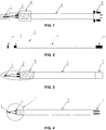
- FIG. 1 is a surface temperature sensor of Example 1.
- the surface temperature sensor comprises an NTC or PTC thermistor 1 and an FPC or FFC 3 comprising two rows of single calendaring copper wires.
- the thermistor 1 is a glass-sealed single-ended NTC thermistor.
- a thermistor pin and the FPC or FFC 3 comprising the two rows of signal calendaring copper wires are welded together to form welding points 2.
- the thermistor 1 and the welding points 2 are packed inside a thin film 4 by hot pressing.
- the thin film 4 is made of a polyimide, a polyethylene terephthalate (PET) plastic, an aramid fiber, an aromatic polyamide, a polyether ether ketone, or a silicone rubber.
- the thin film 4 is divided into an upper layer and a lower layer.
- the thermistor 1, the welding points 2, and a front end part of the FPC or FFC 3 comprising the two rows of single calendaring copper wires are clamped by the thin film 4 and packed together by hot pressing.
- the thin film 4 can be processed into a sleeve shape, so that it only needs to insert the thermistor 1, the welding points 2, and the front end part of the FPC or FFC 3 comprising the two rows of single calendaring copper wires into the sleeve shaped thin film and use the hot pressing package to pack them together.
- the two layers of the thin film are bonded by hot pressing or welding, or via an adhesive or other auxiliary materials.
- a rear part of the FPC or FFC 3 comprising the two rows of single calendaring copper wire is provided with a connector deck 5.
- the FPC or FFC 3 comprising the two rows of single calendaring copper wire is connected to a PCB board by the connector deck 5.
- FIG. 2 A structure diagram of a surface temperature sensor of Example 2 is shown in FIG. 2 .
- the surface temperature sensor comprises a thermistor 1 and a conducting wire 3.
- the conducting wire comprises an upper layer and a lower layer, the upper layer is stacked on the lower layer and is isolated from the lower layer by a thin film.
- the thermistor 1 is a glass-sealed diode type NTC thermistor.
- a thermistor pin and the conducting wire 3 are welded together to form welding points 2.
- the thermistor 1 and the welding points 2 are packed inside the thin film 4 by hot pressing.
- the thin film 4 is made of a polyimide, a polyethylene terephthalate (PET) plastic, an aramid fiber, an aromatic polyamide, a polyether ether ketone, or a silicone rubber.
- the thin film 4 is divided into an upper layer and a lower layer.
- the thermistor 1, the welding points 2, and a front end part of conducting wire 3 are clamped by the thin film 4 and packed together by hot pressing.
- the two layers of the thin film are bonded by hot pressing or welding, or via an adhesive or other auxiliary materials.
- a rear part 6 of the conducting wire 3 is a tin-coated pin which can be directly welded on a PCB board.
- FIG. 3 A structure diagram of a surface temperature sensor of Example 3 is shown in FIG. 3 .
- the surface temperature sensor comprises an NTC or PTC thermistor 1 and an FPC or FFC 3 comprising two rows of single calendaring copper wires.
- the thermistor 1 is a thin film type NTC or PTC thermistor.
- a thermistor pin and the FPC or FFC 3 comprising the two rows of signal calendaring copper wires are welded together to form welding points 2.
- the thermistor 1 and the welding points 2 are packed inside a thin film 4 by hot pressing.
- the thin film 4 is made of a polyimide, a polyethylene terephthalate (PET) plastic, an aramid fiber, an aromatic polyamide, a polyether ether ketone, or a silicone rubber.
- the thin film 4 is divided into an upper layer and a lower layer.
- the thermistor 1, the welding points 2, and a front end part of the FPC or FFC 3 comprising the two rows of single calendaring copper wires are clamped by the thin film 4 and packed together by hot pressing.
- the thin film 4 can be processed into a sleeve shape, so that it only needs to insert the thermistor 1, the welding points 2, and the front end part of the FPC or FFC 3 comprising the two rows of single calendaring copper wires into the sleeve shaped thin film and use the hot pressing package to pack them together.
- the two layers of the thin film are bonded by hot pressing or welding, or via an adhesive or other auxiliary materials.
- a rear part of the FPC or FFC 3 comprising the two rows of single calendaring copper wires is provided with a FFC pin 7 so as to directly insert the FPC or FFC 3 comprising the two rows of single calendaring copper wires into a connector deck.
- FIG. 4 is a surface temperature sensor of Example 4.
- the surface temperature sensor comprises a thermistor 1 and an FPC or FFC 3 comprising two rows of single calendaring copper wires.
- the thermistor 1 is a bare die type NTC or PTC thermistor.
- a thermistor pin and the FPC or FFC 3 comprising the two rows of signal calendaring copper wires are welded together to form welding points 2.
- the thermistor 1 and the welding points 2, and the whole FPC or FFC 3 comprising the two rows of signal calendaring copper wires are packed inside a thin film 4 by hot pressing.
- the thin film 4 is made of a polyimide, a polyethylene terephthalate (PET) plastic, an aramid fiber, an aromatic polyamide, a polyether ether ketone, or a silicone rubber.
- the thin film 4 is divided into an upper layer and a lower layer.
- the thermistor 1, the welding points 2, and the whole FPC or FFC 3 comprising the two rows of single calendaring copper wires are clamped by the thin film 4 and packed together by hot pressing.
- the thin film 4 can be processed into a sleeve shape, so that it only needs to insert the thermistor 1, the welding points 2, and the front end part of the FPC or FFC 3 comprising the two rows of single calendaring copper wires into the sleeve shaped thin film and use the hot pressing package to pack them together.
- the two layers of the thin film are bonded by hot pressing or welding, or via an adhesive or other auxiliary materials.
- a rear part of the FPC or FFC 3 comprising the two rows of single calendaring copper wires is provided with a conducting wire pin 7.
- the FPC or FFC 3 comprising the two rows of single calendaring copper wires and a PCB board are connected by welding via the conducting wire pin 7.
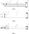
- FIG. 5 is a surface temperature sensor of Example 5.
- the surface temperature sensor comprises two thermistors 1 which are a combination of any two of a thin film type NTC or PTC thermistor, a bare die type NTC or PTC thermistor, a glass-sealed diode type NTC thermistor, and a glass-sealed single-ended NTC thermistor.
- Thermistor pins and conducting wires 3 are connected by welding so as to form welding points 2.
- the conducting wires 3 are arranged side by side from left to right in two rows or are stacked together in an upper layer and a lower layer.
- the thermistors 1, the welding points 2, and the whole conducting lines 3 are packed inside a thin film 4 by hot pressing.
- the thin film 4 is made of a polyimide, a polyethylene terephthalate (PET) plastic, an aramid fiber, an aromatic polyamide, a polyether ether ketone, or a silicone rubber.
- the thin film 4 is divided into an upper layer and a lower layer.
- the two thermistors 1, the welding points 2, and the whole conducting wires 3 are clamped by the thin film 4 and packed together by hot pressing.
- the thin film 4 can be processed into a sleeve shape, so that it only needs to insert the thermistor 1, the welding points 2, and the whole conducting wires 3 into the sleeve shaped thin film and use the hot pressing package to pack them together.
- the two layers of the thin film are bonded by hot pressing or welding, or via an adhesive or other auxiliary materials.
- a connector deck 5 is disposed at rear parts of the conducting wires 3 so as to connect the conducting wires 3 to a PCB board by welding.
- FIG. 6 is a surface temperature sensor of Example 6.
- the surface temperature sensor comprises two thermistors 1 which are a combination of any two of a thin film type NTC or PTC thermistor, a bare die type NTC or PTC thermistor, a glass-sealed diode type NTC thermistor, and a glass-sealed single-ended NTC thermistor.
- Thermistor pins is connected to FPC or FFCs and conducting wires 3 comprising four rows of single calendaring copper wires by welding so as to form welding points 2.
- the two thermistors 1, the welding points 2, and the whole FPC or FFCs and conducting wires 3 comprising the four rows of single calendaring copper wires are packed inside a thin film 4 by hot pressing so that two independent NTC surface temperature sensors are formed.
- the thin film 4 is made of a polyimide, a polyethylene terephthalate (PET) plastic, an aramid fiber, an aromatic polyamide, a polyether ether ketone, or a silicone rubber.
- the thin film 4 is divided into an upper layer and a lower layer.
- the two thermistors 1, the welding points 2, and the whole FPC or FFCs and conducting wires 3 comprising the four rows of single calendaring copper wires are clamped by the thin film 4 and packed together by hot pressing.
- the thin film 4 can be processed into sleeve shapes, so that it only needs to insert the two thermistor 1, the welding points 2, and the whole FPC or FFCs and conducting wires 3 comprising the four rows of single calendaring copper wires into the sleeve shaped thin films 4, respectively, and use the hot pressing package to pack them together.
- the two layers of the thin film are bonded by hot pressing or welding, or via an adhesive or other auxiliary materials.
- a connector deck 5 is disposed at rear parts of the two independent NTC surface temperature sensors so as to connect the independent NTC surface temperature sensors to a PCB board by welding via the FPC or FFCs and conducting wires 3 comprising the four rows of single calendaring copper wires.
- FIG. 7 is a surface temperature sensor of Example 7.
- the surface temperature sensor comprises an NTC thermistor 1 and a flexible flat cable 3.
- the NTC thermistor 1 is a glass-sealed single-ended thermistor.
- a thermistor pin and the flexible flat cable 3 are welded together to form welding points 2.
- the NTC thermistor 1 and the welding points 2 are packed inside a thin film 4 by hot pressing.
- the thin film 4 is made of a polyimide or other materials.
- the thin film 4 is divided into an upper layer and a lower layer.
- the NTC thermistor 1, the welding points 2, and a front end part of the flexible flat cable 3 are clamped by the thin film 4 and packed together by hot pressing.
- the thin film 4 can be processed into a sleeve shape, so that it only needs to insert the NTC thermistor 1, the welding points 2, and the front end part of the flexible flat cable 3 into the sleeve shaped thin film and use the hot pressing package to pack them together.
- a rear part of the flexible flat cable 3 is provided with a connector deck 5 so as to realize connection between the flexible flat cable 3 and a PCB board.
Landscapes
- Physics & Mathematics (AREA)
- General Physics & Mathematics (AREA)
- Nonlinear Science (AREA)
- Measuring Temperature Or Quantity Of Heat (AREA)
- Thermistors And Varistors (AREA)
Claims (4)
- Oberflächentemperatursensor, dadurch gekennzeichnet, dass er umfasst:a) einen Thermistor (1) mit einem negativen Temperaturkoeffizienten (NTC) oder einem positiven Temperaturkoeffizienten (PTC);b) eine flexible gedruckte Schaltung (FPC) oder ein flexibles Flachkabel (FFC) (3), umfassend zumindest zwei Reihen aus metallischen Kupferdrähten; undc) zwei Lagen aus Dünnschichten (4) aus einem Polyimid, einem Polyethylenterephthalat-(PET)-Kunststoff, einer Aramidfaser, einem aromatischen Polyamid oder einem Polyetheretherketon;wobei
der NTC- oder PTC-Thermistor (1) mit Thermistor-Verbindungsstiften versehen ist, der NTC- oder PTC-Thermistor (1) vollständig innerhalb der Dünnschichten aus einem Polyimid, einem Polyethylenterephthalat-(PET)-Kunststoff, einer Aramidfaser, einem aromatischen Polyamid oder einem Polyetheretherketon gepackt ist;
die Thermistor-Verbindungsstifte des NTC- oder PTC-Thermistors (1) und der vordere Endteil der FPC oder des FFC (3) miteinander verbunden sind, um Schweißpunkte (2) zu bilden; der gesamte Thermistor (1), die Schweißpunkte (2) und der vordere Endteil der FPC oder des FFC (3) innerhalb der Dünnschichten (4) gepackt sind; und die metallischen Kupferdrähte der FPC oder des FFC (3) von links nach rechts in zwei Reihen nebeneinander angeordnet sind oder in einer oberen Lage und einer unteren Lage übereinander gestapelt sind. - Sensor nach Anspruch 1, dadurch gekennzeichnet, dass der Thermistor (1) ein glasversiegelter einendiger NTC-Thermistor oder ein glasversiegelter NTC-Thermistor vom Diodentyp ist.
- Sensor nach Anspruch 1, dadurch gekennzeichnet, dass ein hinterer Teil der FPC oder des FFC (3) mit einer Verbindungsplatte versehen ist.
- Sensor nach Anspruch 1, dadurch gekennzeichnet, dass ein hinterer Teil der FPC oder des FFC (3) mit einem FFC-Verbindungsstift versehen ist.
Applications Claiming Priority (4)
| Application Number | Priority Date | Filing Date | Title |
|---|---|---|---|
| CN2012101484008A CN102636284A (zh) | 2012-05-14 | 2012-05-14 | Ntc表面测温温度传感器 |
| CN2012102357423A CN102735367A (zh) | 2012-07-09 | 2012-07-09 | 表面测温温度传感器 |
| CN201210340007.9A CN102914382B (zh) | 2012-05-14 | 2012-09-14 | 表面测温温度传感器 |
| PCT/CN2013/074367 WO2013170685A1 (zh) | 2012-05-14 | 2013-04-18 | 表面测温温度传感器 |
Publications (3)
| Publication Number | Publication Date |
|---|---|
| EP2851664A1 EP2851664A1 (de) | 2015-03-25 |
| EP2851664A4 EP2851664A4 (de) | 2016-01-20 |
| EP2851664B1 true EP2851664B1 (de) | 2019-06-05 |
Family
ID=49583101
Family Applications (1)
| Application Number | Title | Priority Date | Filing Date |
|---|---|---|---|
| EP13791419.8A Active EP2851664B1 (de) | 2012-05-14 | 2013-04-18 | Oberflächentemperaturmessfühler |
Country Status (4)
| Country | Link |
|---|---|
| US (1) | US9989421B2 (de) |
| EP (1) | EP2851664B1 (de) |
| JP (1) | JP6278957B2 (de) |
| WO (1) | WO2013170685A1 (de) |
Families Citing this family (13)
| Publication number | Priority date | Publication date | Assignee | Title |
|---|---|---|---|---|
| JP5523982B2 (ja) * | 2010-08-16 | 2014-06-18 | 株式会社芝浦電子 | 温度センサ |
| CN103207032A (zh) * | 2012-01-13 | 2013-07-17 | 热敏碟公司 | 低型面温度传感器探针 |
| US10784635B2 (en) | 2015-12-18 | 2020-09-22 | Shenzhen Minjie Electronics Tech Co., Ltd. | Sensing apparatus, piercing terminal, stamping strip and corresponding methods |
| KR102059612B1 (ko) * | 2016-08-24 | 2019-12-26 | 주식회사 엘지화학 | 전지모듈 내에서 공간을 적게 점유하는 상호 연결 부재 및 이를 포함하는 전지모듈 |
| US10585003B2 (en) * | 2017-03-07 | 2020-03-10 | Hamilton Sundstrand Corporation | Temperature measurement integrated circuit with flexible cable and sensing element |
| CN114846311B (zh) * | 2020-01-14 | 2025-03-04 | 株式会社芝浦电子 | 温度传感器及温度传感器的制造方法 |
| DE102020110438A1 (de) * | 2020-04-16 | 2021-10-21 | Tdk Electronics Ag | Sensor mit Gehäuse |
| CN114694903A (zh) * | 2020-12-29 | 2022-07-01 | 深圳新时恒电子科技有限公司 | 一种基于贴片式的负温度系数热敏电阻器及制备方法 |
| CN112615073B (zh) * | 2020-12-31 | 2023-05-26 | 上海捷新动力电池系统有限公司 | 一种动力电池包内ffc温度采样结构及其工艺流程 |
| DE112021000268T5 (de) * | 2021-10-14 | 2023-08-03 | Shibaura Electronics Co., Ltd. | Temperatursensor und Verfahren zur Herstellung eines Temperatursensors |
| CN115295967A (zh) * | 2022-08-18 | 2022-11-04 | 深圳市驭能科技有限公司 | 一种用于电池模组的集成采集母排 |
| CH720605A1 (de) * | 2023-03-13 | 2024-09-30 | Daetwyler Schweiz Ag | Flexible blattartige Sensorvorrichtung für Temperaturverteilungsmessungen in einem Batteriepack |
| US12446156B2 (en) | 2023-05-19 | 2025-10-14 | Arista Networks, Inc. | Network device with elevated temperature sensor |
Citations (3)
| Publication number | Priority date | Publication date | Assignee | Title |
|---|---|---|---|---|
| JPS55122130U (de) * | 1979-02-23 | 1980-08-30 | ||
| US4789850A (en) * | 1987-12-07 | 1988-12-06 | Robertshaw Controls Company | Temperature sensor construction and method of making the same |
| CN202048997U (zh) * | 2011-05-09 | 2011-11-23 | 肇庆爱晟电子科技有限公司 | 防水抗老化高可靠温度传感器 |
Family Cites Families (25)
| Publication number | Priority date | Publication date | Assignee | Title |
|---|---|---|---|---|
| US4317367A (en) * | 1977-03-18 | 1982-03-02 | Milton Schonberger | Fever thermometer, or the like sensor |
| JPS6124905Y2 (de) * | 1980-06-27 | 1986-07-26 | ||
| JPH0434434Y2 (de) * | 1984-12-28 | 1992-08-17 | ||
| JPH0231738Y2 (de) * | 1986-09-24 | 1990-08-28 | ||
| US5190048A (en) * | 1991-09-17 | 1993-03-02 | Healthdyne, Inc. | Thermistor airflow sensor assembly |
| US5413111A (en) * | 1993-08-24 | 1995-05-09 | Healthdyne Technologies, Inc. | Bead thermistor airflow sensor assembly |
| JP3223716B2 (ja) * | 1994-08-30 | 2001-10-29 | 三菱マテリアル株式会社 | サーミスタセンサ |
| JPH08128901A (ja) * | 1994-10-31 | 1996-05-21 | Sanyo Electric Co Ltd | 温度センサーとパック電池 |
| US6431750B1 (en) * | 1999-12-14 | 2002-08-13 | Sierra Lobo, Inc. | Flexible temperature sensing probe |
| DE10036900C2 (de) * | 2000-07-28 | 2002-07-11 | Siemens Ag | Verfahren zur Kontaktierung einer flexiblen Leiterplatte mit einem Kontaktpartner und Anordnung aus flexibler Leiterplatte und Kontaktpartner |
| JP2003005575A (ja) * | 2001-06-22 | 2003-01-08 | Murata Mach Ltd | 定着装置の温度検出器 |
| WO2006122394A1 (en) * | 2005-05-20 | 2006-11-23 | Trojan Technologies Inc. | Ultraviolet radiation lamp and source module and treatment system containing same |
| JP2008026200A (ja) * | 2006-07-24 | 2008-02-07 | Matsushita Electric Ind Co Ltd | 温度センサとそれを備えた暖房便座装置 |
| JP2010038763A (ja) * | 2008-08-06 | 2010-02-18 | Nippon Soken Inc | センサ装置の製造方法 |
| KR101038755B1 (ko) * | 2008-10-09 | 2011-06-03 | 조인셋 주식회사 | 세라믹 칩 어셈블리 |
| US8794827B2 (en) * | 2009-02-02 | 2014-08-05 | Yazaki Corporation | Thermal sensing structure and insulating structure of thermal sensing circuit |
| JP5249143B2 (ja) * | 2009-06-25 | 2013-07-31 | 三菱電線工業株式会社 | 端子付センサ |
| CN101922980A (zh) * | 2010-07-23 | 2010-12-22 | 深圳市敏杰电子科技有限公司 | Ntc温度传感器及其成型工艺 |
| US8523430B2 (en) * | 2010-07-28 | 2013-09-03 | Lattron Co. Ltd. | Ultra thin temperature sensor device |
| JP5494968B2 (ja) * | 2010-09-24 | 2014-05-21 | 三菱マテリアル株式会社 | 温度センサ |
| US8336198B2 (en) * | 2010-10-29 | 2012-12-25 | Cheng Jen Tien | Automatic feeding and crimping device of applicator in terminal making machine for flexible printed circuits, flat cables and cable terminals |
| KR101062752B1 (ko) * | 2011-03-16 | 2011-09-06 | (주) 래트론 | 초박형 센서소자 및 그 제조방법 |
| CN102636284A (zh) * | 2012-05-14 | 2012-08-15 | 花国樑 | Ntc表面测温温度传感器 |
| CN102735367A (zh) * | 2012-07-09 | 2012-10-17 | 深圳市敏杰电子科技有限公司 | 表面测温温度传感器 |
| CN202676321U (zh) * | 2012-07-17 | 2013-01-16 | 昆山雅森电子材料科技有限公司 | 锂离子电池温度感应器 |
-
2013
- 2013-04-18 WO PCT/CN2013/074367 patent/WO2013170685A1/zh not_active Ceased
- 2013-04-18 EP EP13791419.8A patent/EP2851664B1/de active Active
- 2013-04-18 JP JP2015511910A patent/JP6278957B2/ja active Active
-
2014
- 2014-11-06 US US14/534,196 patent/US9989421B2/en active Active
Patent Citations (3)
| Publication number | Priority date | Publication date | Assignee | Title |
|---|---|---|---|---|
| JPS55122130U (de) * | 1979-02-23 | 1980-08-30 | ||
| US4789850A (en) * | 1987-12-07 | 1988-12-06 | Robertshaw Controls Company | Temperature sensor construction and method of making the same |
| CN202048997U (zh) * | 2011-05-09 | 2011-11-23 | 肇庆爱晟电子科技有限公司 | 防水抗老化高可靠温度传感器 |
Also Published As
| Publication number | Publication date |
|---|---|
| JP6278957B2 (ja) | 2018-02-14 |
| EP2851664A1 (de) | 2015-03-25 |
| EP2851664A4 (de) | 2016-01-20 |
| JP2016536565A (ja) | 2016-11-24 |
| WO2013170685A1 (zh) | 2013-11-21 |
| US9989421B2 (en) | 2018-06-05 |
| US20150063423A1 (en) | 2015-03-05 |
| WO2013170685A8 (zh) | 2016-08-04 |
Similar Documents
| Publication | Publication Date | Title |
|---|---|---|
| EP2851664B1 (de) | Oberflächentemperaturmessfühler | |
| CN102914382B (zh) | 表面测温温度传感器 | |
| JP6297765B1 (ja) | 温度センサ | |
| US20180034115A1 (en) | Temperature measuring assembly, electrical device assembly, battery pack connecting assembly and battery pack | |
| CN102735367A (zh) | 表面测温温度传感器 | |
| KR101038755B1 (ko) | 세라믹 칩 어셈블리 | |
| CN205861226U (zh) | 温度测量装置、电器组件及电池包 | |
| US8859909B2 (en) | Flexible cable for low profile electrical device | |
| CN204788709U (zh) | 薄膜型温度传感器 | |
| US20090135882A1 (en) | Sensor Arrangement | |
| KR20100130147A (ko) | 온도 센서 | |
| JP6497133B2 (ja) | 温度センサ | |
| CN115884500A (zh) | 一种弹性fpc板及其制作方法和应用弹性fpc板的产品 | |
| CN114128011A (zh) | 布线模块 | |
| JP2014168037A (ja) | 電子部品 | |
| CN106248242A (zh) | 一种快速绝缘型平面测温ntc温度传感器 | |
| CN212963757U (zh) | 一种温度传感元件、测温组件及电池包 | |
| CN117769125A (zh) | 柔性电路板及其制作方法 | |
| CN112599937B (zh) | 电池采集方法及电池采集系统 | |
| US20260098761A1 (en) | Bus bar temperature sensor, and bus bar module and method of manufacturing the same | |
| CN214173616U (zh) | 一种压力传感器 | |
| CN212030769U (zh) | 温度传感器组件、电连接组件及电池包 | |
| CN104364940A (zh) | 用于电子结构元件的保护装置、电路、电化学蓄能器、用于制造电路的方法以及柔性罩层的用途 | |
| KR102750044B1 (ko) | Ntc서미스터소자 패키지를 이용한 멀티채널 온도센서 | |
| CN112033561A (zh) | 一种温度传感元件、测温组件及电池包 |
Legal Events
| Date | Code | Title | Description |
|---|---|---|---|
| PUAI | Public reference made under article 153(3) epc to a published international application that has entered the european phase |
Free format text: ORIGINAL CODE: 0009012 |
|
| 17P | Request for examination filed |
Effective date: 20141113 |
|
| AK | Designated contracting states |
Kind code of ref document: A1 Designated state(s): AL AT BE BG CH CY CZ DE DK EE ES FI FR GB GR HR HU IE IS IT LI LT LU LV MC MK MT NL NO PL PT RO RS SE SI SK SM TR |
|
| AX | Request for extension of the european patent |
Extension state: BA ME |
|
| DAX | Request for extension of the european patent (deleted) | ||
| RA4 | Supplementary search report drawn up and despatched (corrected) |
Effective date: 20151217 |
|
| RIC1 | Information provided on ipc code assigned before grant |
Ipc: G01K 7/22 20060101AFI20151211BHEP Ipc: G01K 1/08 20060101ALI20151211BHEP |
|
| STAA | Information on the status of an ep patent application or granted ep patent |
Free format text: STATUS: EXAMINATION IS IN PROGRESS |
|
| 17Q | First examination report despatched |
Effective date: 20170125 |
|
| GRAP | Despatch of communication of intention to grant a patent |
Free format text: ORIGINAL CODE: EPIDOSNIGR1 |
|
| STAA | Information on the status of an ep patent application or granted ep patent |
Free format text: STATUS: GRANT OF PATENT IS INTENDED |
|
| INTG | Intention to grant announced |
Effective date: 20181210 |
|
| GRAS | Grant fee paid |
Free format text: ORIGINAL CODE: EPIDOSNIGR3 |
|
| GRAA | (expected) grant |
Free format text: ORIGINAL CODE: 0009210 |
|
| STAA | Information on the status of an ep patent application or granted ep patent |
Free format text: STATUS: THE PATENT HAS BEEN GRANTED |
|
| AK | Designated contracting states |
Kind code of ref document: B1 Designated state(s): AL AT BE BG CH CY CZ DE DK EE ES FI FR GB GR HR HU IE IS IT LI LT LU LV MC MK MT NL NO PL PT RO RS SE SI SK SM TR |
|
| REG | Reference to a national code |
Ref country code: GB Ref legal event code: FG4D |
|
| REG | Reference to a national code |
Ref country code: CH Ref legal event code: EP |
|
| REG | Reference to a national code |
Ref country code: AT Ref legal event code: REF Ref document number: 1140493 Country of ref document: AT Kind code of ref document: T Effective date: 20190615 |
|
| REG | Reference to a national code |
Ref country code: DE Ref legal event code: R096 Ref document number: 602013056257 Country of ref document: DE |
|
| REG | Reference to a national code |
Ref country code: IE Ref legal event code: FG4D |
|
| REG | Reference to a national code |
Ref country code: NL Ref legal event code: MP Effective date: 20190605 |
|
| REG | Reference to a national code |
Ref country code: LT Ref legal event code: MG4D |
|
| PG25 | Lapsed in a contracting state [announced via postgrant information from national office to epo] |
Ref country code: LT Free format text: LAPSE BECAUSE OF FAILURE TO SUBMIT A TRANSLATION OF THE DESCRIPTION OR TO PAY THE FEE WITHIN THE PRESCRIBED TIME-LIMIT Effective date: 20190605 Ref country code: ES Free format text: LAPSE BECAUSE OF FAILURE TO SUBMIT A TRANSLATION OF THE DESCRIPTION OR TO PAY THE FEE WITHIN THE PRESCRIBED TIME-LIMIT Effective date: 20190605 Ref country code: SE Free format text: LAPSE BECAUSE OF FAILURE TO SUBMIT A TRANSLATION OF THE DESCRIPTION OR TO PAY THE FEE WITHIN THE PRESCRIBED TIME-LIMIT Effective date: 20190605 Ref country code: HR Free format text: LAPSE BECAUSE OF FAILURE TO SUBMIT A TRANSLATION OF THE DESCRIPTION OR TO PAY THE FEE WITHIN THE PRESCRIBED TIME-LIMIT Effective date: 20190605 Ref country code: NO Free format text: LAPSE BECAUSE OF FAILURE TO SUBMIT A TRANSLATION OF THE DESCRIPTION OR TO PAY THE FEE WITHIN THE PRESCRIBED TIME-LIMIT Effective date: 20190905 Ref country code: FI Free format text: LAPSE BECAUSE OF FAILURE TO SUBMIT A TRANSLATION OF THE DESCRIPTION OR TO PAY THE FEE WITHIN THE PRESCRIBED TIME-LIMIT Effective date: 20190605 Ref country code: AL Free format text: LAPSE BECAUSE OF FAILURE TO SUBMIT A TRANSLATION OF THE DESCRIPTION OR TO PAY THE FEE WITHIN THE PRESCRIBED TIME-LIMIT Effective date: 20190605 |
|
| PG25 | Lapsed in a contracting state [announced via postgrant information from national office to epo] |
Ref country code: LV Free format text: LAPSE BECAUSE OF FAILURE TO SUBMIT A TRANSLATION OF THE DESCRIPTION OR TO PAY THE FEE WITHIN THE PRESCRIBED TIME-LIMIT Effective date: 20190605 Ref country code: GR Free format text: LAPSE BECAUSE OF FAILURE TO SUBMIT A TRANSLATION OF THE DESCRIPTION OR TO PAY THE FEE WITHIN THE PRESCRIBED TIME-LIMIT Effective date: 20190906 Ref country code: BG Free format text: LAPSE BECAUSE OF FAILURE TO SUBMIT A TRANSLATION OF THE DESCRIPTION OR TO PAY THE FEE WITHIN THE PRESCRIBED TIME-LIMIT Effective date: 20190905 Ref country code: RS Free format text: LAPSE BECAUSE OF FAILURE TO SUBMIT A TRANSLATION OF THE DESCRIPTION OR TO PAY THE FEE WITHIN THE PRESCRIBED TIME-LIMIT Effective date: 20190605 |
|
| REG | Reference to a national code |
Ref country code: AT Ref legal event code: MK05 Ref document number: 1140493 Country of ref document: AT Kind code of ref document: T Effective date: 20190605 |
|
| PG25 | Lapsed in a contracting state [announced via postgrant information from national office to epo] |
Ref country code: CZ Free format text: LAPSE BECAUSE OF FAILURE TO SUBMIT A TRANSLATION OF THE DESCRIPTION OR TO PAY THE FEE WITHIN THE PRESCRIBED TIME-LIMIT Effective date: 20190605 Ref country code: SK Free format text: LAPSE BECAUSE OF FAILURE TO SUBMIT A TRANSLATION OF THE DESCRIPTION OR TO PAY THE FEE WITHIN THE PRESCRIBED TIME-LIMIT Effective date: 20190605 Ref country code: RO Free format text: LAPSE BECAUSE OF FAILURE TO SUBMIT A TRANSLATION OF THE DESCRIPTION OR TO PAY THE FEE WITHIN THE PRESCRIBED TIME-LIMIT Effective date: 20190605 Ref country code: PT Free format text: LAPSE BECAUSE OF FAILURE TO SUBMIT A TRANSLATION OF THE DESCRIPTION OR TO PAY THE FEE WITHIN THE PRESCRIBED TIME-LIMIT Effective date: 20191007 Ref country code: NL Free format text: LAPSE BECAUSE OF FAILURE TO SUBMIT A TRANSLATION OF THE DESCRIPTION OR TO PAY THE FEE WITHIN THE PRESCRIBED TIME-LIMIT Effective date: 20190605 Ref country code: AT Free format text: LAPSE BECAUSE OF FAILURE TO SUBMIT A TRANSLATION OF THE DESCRIPTION OR TO PAY THE FEE WITHIN THE PRESCRIBED TIME-LIMIT Effective date: 20190605 Ref country code: EE Free format text: LAPSE BECAUSE OF FAILURE TO SUBMIT A TRANSLATION OF THE DESCRIPTION OR TO PAY THE FEE WITHIN THE PRESCRIBED TIME-LIMIT Effective date: 20190605 |
|
| PG25 | Lapsed in a contracting state [announced via postgrant information from national office to epo] |
Ref country code: IT Free format text: LAPSE BECAUSE OF FAILURE TO SUBMIT A TRANSLATION OF THE DESCRIPTION OR TO PAY THE FEE WITHIN THE PRESCRIBED TIME-LIMIT Effective date: 20190605 Ref country code: IS Free format text: LAPSE BECAUSE OF FAILURE TO SUBMIT A TRANSLATION OF THE DESCRIPTION OR TO PAY THE FEE WITHIN THE PRESCRIBED TIME-LIMIT Effective date: 20191005 Ref country code: SM Free format text: LAPSE BECAUSE OF FAILURE TO SUBMIT A TRANSLATION OF THE DESCRIPTION OR TO PAY THE FEE WITHIN THE PRESCRIBED TIME-LIMIT Effective date: 20190605 |
|
| REG | Reference to a national code |
Ref country code: DE Ref legal event code: R097 Ref document number: 602013056257 Country of ref document: DE |
|
| PG25 | Lapsed in a contracting state [announced via postgrant information from national office to epo] |
Ref country code: TR Free format text: LAPSE BECAUSE OF FAILURE TO SUBMIT A TRANSLATION OF THE DESCRIPTION OR TO PAY THE FEE WITHIN THE PRESCRIBED TIME-LIMIT Effective date: 20190605 |
|
| PLBE | No opposition filed within time limit |
Free format text: ORIGINAL CODE: 0009261 |
|
| STAA | Information on the status of an ep patent application or granted ep patent |
Free format text: STATUS: NO OPPOSITION FILED WITHIN TIME LIMIT |
|
| PG25 | Lapsed in a contracting state [announced via postgrant information from national office to epo] |
Ref country code: DK Free format text: LAPSE BECAUSE OF FAILURE TO SUBMIT A TRANSLATION OF THE DESCRIPTION OR TO PAY THE FEE WITHIN THE PRESCRIBED TIME-LIMIT Effective date: 20190605 Ref country code: PL Free format text: LAPSE BECAUSE OF FAILURE TO SUBMIT A TRANSLATION OF THE DESCRIPTION OR TO PAY THE FEE WITHIN THE PRESCRIBED TIME-LIMIT Effective date: 20190605 |
|
| 26N | No opposition filed |
Effective date: 20200306 |
|
| PG25 | Lapsed in a contracting state [announced via postgrant information from national office to epo] |
Ref country code: SI Free format text: LAPSE BECAUSE OF FAILURE TO SUBMIT A TRANSLATION OF THE DESCRIPTION OR TO PAY THE FEE WITHIN THE PRESCRIBED TIME-LIMIT Effective date: 20190605 |
|
| PG25 | Lapsed in a contracting state [announced via postgrant information from national office to epo] |
Ref country code: MC Free format text: LAPSE BECAUSE OF FAILURE TO SUBMIT A TRANSLATION OF THE DESCRIPTION OR TO PAY THE FEE WITHIN THE PRESCRIBED TIME-LIMIT Effective date: 20190605 |
|
| REG | Reference to a national code |
Ref country code: CH Ref legal event code: PL |
|
| PG25 | Lapsed in a contracting state [announced via postgrant information from national office to epo] |
Ref country code: CH Free format text: LAPSE BECAUSE OF NON-PAYMENT OF DUE FEES Effective date: 20200430 Ref country code: LU Free format text: LAPSE BECAUSE OF NON-PAYMENT OF DUE FEES Effective date: 20200418 Ref country code: LI Free format text: LAPSE BECAUSE OF NON-PAYMENT OF DUE FEES Effective date: 20200430 |
|
| REG | Reference to a national code |
Ref country code: BE Ref legal event code: MM Effective date: 20200430 |
|
| PG25 | Lapsed in a contracting state [announced via postgrant information from national office to epo] |
Ref country code: BE Free format text: LAPSE BECAUSE OF NON-PAYMENT OF DUE FEES Effective date: 20200430 |
|
| GBPC | Gb: european patent ceased through non-payment of renewal fee |
Effective date: 20200418 |
|
| PG25 | Lapsed in a contracting state [announced via postgrant information from national office to epo] |
Ref country code: IE Free format text: LAPSE BECAUSE OF NON-PAYMENT OF DUE FEES Effective date: 20200418 Ref country code: GB Free format text: LAPSE BECAUSE OF NON-PAYMENT OF DUE FEES Effective date: 20200418 |
|
| PG25 | Lapsed in a contracting state [announced via postgrant information from national office to epo] |
Ref country code: MT Free format text: LAPSE BECAUSE OF FAILURE TO SUBMIT A TRANSLATION OF THE DESCRIPTION OR TO PAY THE FEE WITHIN THE PRESCRIBED TIME-LIMIT Effective date: 20190605 Ref country code: CY Free format text: LAPSE BECAUSE OF FAILURE TO SUBMIT A TRANSLATION OF THE DESCRIPTION OR TO PAY THE FEE WITHIN THE PRESCRIBED TIME-LIMIT Effective date: 20190605 |
|
| PG25 | Lapsed in a contracting state [announced via postgrant information from national office to epo] |
Ref country code: MK Free format text: LAPSE BECAUSE OF FAILURE TO SUBMIT A TRANSLATION OF THE DESCRIPTION OR TO PAY THE FEE WITHIN THE PRESCRIBED TIME-LIMIT Effective date: 20190605 |
|
| PGFP | Annual fee paid to national office [announced via postgrant information from national office to epo] |
Ref country code: DE Payment date: 20250319 Year of fee payment: 13 |
|
| PGFP | Annual fee paid to national office [announced via postgrant information from national office to epo] |
Ref country code: FR Payment date: 20260309 Year of fee payment: 14 |