EP2851677A1 - Technique de balayage multilignes - Google Patents
Technique de balayage multilignes Download PDFInfo
- Publication number
- EP2851677A1 EP2851677A1 EP13004613.9A EP13004613A EP2851677A1 EP 2851677 A1 EP2851677 A1 EP 2851677A1 EP 13004613 A EP13004613 A EP 13004613A EP 2851677 A1 EP2851677 A1 EP 2851677A1
- Authority
- EP
- European Patent Office
- Prior art keywords
- line
- measurement
- image
- lines
- measurement object
- Prior art date
- Legal status (The legal status is an assumption and is not a legal conclusion. Google has not performed a legal analysis and makes no representation as to the accuracy of the status listed.)
- Granted
Links
Images


Classifications
-
- G—PHYSICS
- G01—MEASURING; TESTING
- G01N—INVESTIGATING OR ANALYSING MATERIALS BY DETERMINING THEIR CHEMICAL OR PHYSICAL PROPERTIES
- G01N21/00—Investigating or analysing materials by the use of optical means, i.e. using sub-millimetre waves, infrared, visible or ultraviolet light
- G01N21/84—Systems specially adapted for particular applications
- G01N21/88—Investigating the presence of flaws or contamination
- G01N21/90—Investigating the presence of flaws or contamination in a container or its contents
- G01N21/9036—Investigating the presence of flaws or contamination in a container or its contents using arrays of emitters or receivers
-
- G—PHYSICS
- G01—MEASURING; TESTING
- G01N—INVESTIGATING OR ANALYSING MATERIALS BY DETERMINING THEIR CHEMICAL OR PHYSICAL PROPERTIES
- G01N21/00—Investigating or analysing materials by the use of optical means, i.e. using sub-millimetre waves, infrared, visible or ultraviolet light
- G01N21/84—Systems specially adapted for particular applications
- G01N21/88—Investigating the presence of flaws or contamination
- G01N21/95—Investigating the presence of flaws or contamination characterised by the material or shape of the object to be examined
- G01N21/952—Inspecting the exterior surface of cylindrical bodies or wires
Definitions
- the present invention relates to a method for the optical inspection of a measurement object.
- a method for testing test tubes is known.
- a test tube is rotated about its longitudinal axis and scanned by means of a CCD sensor array. Signals from the CCD sensor array are weighted by their location in the array.
- the disclosed method offers only limited measurement success, since location points of the test tube surface appear at different distances and at different angles, and since the weighting of signals corresponding to the location points only approximately compensate for the inaccuracy resulting from distances and angles.
- DE 199 53 415 C1 discloses a method for detecting surface defects of a measuring object which is guided on a conveyor belt under a camera.
- the camera takes thermographic data. Different image lines correspond to different distances of the target surface from the camera.
- the approach leaves open questions about the appropriate exploitation of the data.
- the present invention is therefore based on the object to achieve the most accurate possible verification of a DUT.
- this object is achieved by a method for optically examining a measurement object, comprising rotating the measurement object about an axis of rotation and at the same time repeatedly scanning the measurement object by an optical sensor having a number of image lines, wherein the scanning comprises capturing at least two measurement lines spaced apart from one another the measurement object is included in respective image lines, each measurement line being associated with at least one image line and being detected as a line image, and each image line capturing the measurement object at a measurement line associated with that image line at a different angle with respect to a surface of the measurement object; and merging all the line images associated with a measurement line into a respective composite image.
- the method further comprises performing a feature analysis by comparing the composite images.
- the measurement object has a circular cross-section.
- the axis of rotation is a longitudinal axis of the measurement object.
- the circular cross section of the measurement object can vary according to the length of the measurement object.
- the measurement object consists of glass.
- the measurement object is a syringe body of a syringe, in particular a glass syringe.
- the optical sensor is part of a camera.
- an embodiment is preferred in which the image lines in the optical sensor are arranged in a plane.
- an embodiment is preferred in which, prior to the beginning of the scanning, at least one image line assigned to each measuring line is selected from the image lines of the optical sensor.
- the measurement lines are detected from parallel viewing directions, for example with a telecentric lens.
- the measurement lines are detected centrally in perspective, for example with an entocentric objective.
- At least one image line of the optical sensor is read out before the beginning of the scanning, and the alignment of the measurement object with respect to the optical sensor is determined on the basis of the image line.
- the entire sensor is read before the beginning of the scanning.
- the camera is aligned so that the measurement object is detected at a certain angle to the horizontal, for example, exactly horizontal.
- the image lines are arranged parallel to the axis of rotation.
- the dimensions of the composite image may correspond to the direction of the rotation axis and to the circumference of the measurement object projected in a plane.
- the image lines in the optical sensor need not be exactly parallel to the axis of rotation, but may deviate slightly from this constellation, for example by a tolerance range of 5 degrees.
- the invention can also develop its advantages with other angles between the axis of rotation and image lines, as long as an angle of 45 degrees is not reached or exceeded.
- the line images recorded with image lines contain image data recorded by a measurement line.
- the picture lines may be lines of recording elements within the optical sensor.
- steps of turning and grasping can be coordinated so that the resulting line images can be joined together seamlessly, without overlapping successive line images or gaps between successive line images. It is within the skill of the art to perform rotation and detection in steps, wherein each step corresponds to rotating the measurement object by a predetermined angle, and wherein this angle is selected to detect seamlessly combinable line images.
- the invention provides a plurality of composite images each containing information about the target surface at a single angle with respect to that surface and at a single distance from the camera. In this way, inaccuracies based on different angles and / or distances are advantageously avoided.
- the invention is based on the surprising finding that a high information density per image is achieved by one or more image lines recorded in parallel perspective while simultaneously rotating the measurement object.
- the images contain common information resulting from the differences between the images.
- the resulting images provide a powerful data foundation for further analysis.
- the method can also be implemented with simple means.
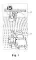
- FIG. 1 For example, a measuring object 100 is shown in the longitudinal direction, which is to be checked for errors.
- the measuring object 100 preferably has a circular cross-section, which may vary in the longitudinal direction of the measuring object 100.
- the measurement object 100 may have a bottle shape.
- the measuring object 100 shown here represents a syringe body of a glass syringe, however, the method according to the invention is suitable for checking any measuring objects with a circular cross-section. Alternatively, the method can also be used for bodies with a different cross section.
- the errors to be detected may be superficial and may be scratches or scars, for example. If the measurement object 100 is transparent or at least partially transparent, the method according to the invention can also detect errors that extend from the surface into the measurement object 100, for example, cracks, or even completely contained in the measurement object 100. According to a particular embodiment, which will be explained below, the invention provides data to distinguish more superficial from deeper errors.
- FIG. 1 shows the measurement object 100 from a possible viewing direction of a camera 200.
- measuring lines a, b and c are drawn, which are to be recorded by the camera 200.
- the number of measurement lines shown is only an example; the advantages of the invention can be achieved with any number of measuring lines.
- All measurement lines are substantially parallel to a rotation axis 110, for example a longitudinal axis, of the measurement object 100.
- the viewing plane of the camera 200 on the measurement line b is perpendicular to the surface of the measurement object 100, while the view planes on the measurement lines a and c with the surface of the DUT 100 due to its curvature or due to its circular cross-section form an obtuse or acute angle.
- the measurement lines a and c can be detected under an angle deviation with respect to the perpendicular angle of plus or minus up to 30 degrees, preferably up to ten degrees.
- the number and spacing of the measurement lines can vary. Preferably, however, at least two measurement lines are used.
- FIG. 2 is a side view of an exemplary apparatus for performing the method according to the invention shown.
- FIG. 3 a perspective view of the exemplary device.
- the measuring object 100 is shown in cross-section with the longitudinal axis as the center.
- signals of the measurement lines a, b and c are received via one or more lenses (objective) 210 in a camera 200 and there by a sensor 220.
- a plurality of sensors may be used which only receive signals of the measurement lines a, b and c, respectively, and thus enable the recording of a parallel perspective.
- a substantially parallel perspective is also possible with the construction shown and a single area sensor, for example by assigning areas of the sensor 220 to the signals of the measurement lines a, b and c.
- the invention unfolds its advantages even when using a camera with central perspective image acquisition.
- the measuring object 100 can be rotated continuously about its longitudinal axis. Alternatively, the rotation can also take place about another axis. In this case, optical signals of the measurement object 100 are received by the sensor or sensors 220.
- the images are continuously repeated in order to maximize all surface areas of the test object 100 to capture. With each shot, all object points along the predefined measurement lines are captured in corresponding image lines, in the present example all object points along the measurement lines a, b and c on the surface of the measurement object 100.
- Composite images are generated from the image lines. Preferably, an image is generated for each measurement line, which is composed of the image lines of this measurement line.
- Each of the images contains surface points of the measurement object 100 along a measurement line corresponding to the image along a first, for example horizontal, image axis.
- a single area sensor 220 containing a plurality of photosensitive elements is used as the sensor.
- the photosensitive elements may, for example, be arranged in a matrix. Lines of the matrix correspond to image lines. Certain lines of the matrix can be selected to capture the signals of a particular measurement line. In this case, it is advantageous to select the distances of the lines in such a way that they permit directions of view which are as parallel as possible to the measurement line.
- the composite images already explained above are then assembled only from the predetermined image lines. Unselected picture lines do not need to be further processed, so that the method according to the invention works particularly fast.
- An exemplary resolution of a sensor comprises 4092x3072 pixels. With conventional reading then fall continuously about 12 megapixels per recording. Using the present invention, this amount of data is reduced to, for example 3x4092 pixels (with three image lines). This corresponds to only about 0.1% of the total image information of the sensor. This information is then read several times in synchronism with the rotation to produce an image.
- a lighting fixture 230 is shown.
- the illumination body can lie behind the measurement object 100 from the viewing direction of the camera 200.
- the illumination body 230 may be disposed between the camera 200 and the measurement object 100 or elsewhere to take advantage of further illumination effects.
- FIG. 4 shows examples of photographs that were taken on the basis of three measurement or image lines.
- Each of the three images shows the same object area of the same measurement object 100. However, all image lines of a respective image were taken at the same angle with respect to the object surface. In each of the three images, scratches are visible in the middle and on the right, which is therefore visible regardless of the angle. In the left half of the pictures a crack is visible, which however appears differently depending on the angle.
- the composite images produced by the method according to the invention are suitable for further analysis. Since the same surface data appear at different angles, but otherwise no significant differences occur - for example, different depths or different distortions due to a pure central perspective - image features can be identified and classified by comparing the images. Relevant methods are suitable for this purpose, such as forming difference images, identifying maxima and minima, comparing maxima and minima in the different images. In particular, a comparison of the composite images may serve to classify errors. For certain materials of the DUT 100, deeper defects such as cracks, depending on the angle, appear different from superficial defects such as scratches or scars. If a certain type of error appears only at a certain angle and another type of error at several angles or at a different angle, a comparative analysis of the images provides information about the respective error.
- Triangulation is a method of determining a distance of a distant point from the location of two known points and the angles between each of a straight line through one of the known points and the distant point with a straight line through both known points.
- the distance from a base length b between two known points s 1 and s 2 to a distant point may be determined by two angles ⁇ and ⁇ between straight lines through s 1 and s 2 and a respective straight line through s 1 and the remote point s 2 and the distant point.
- FIG. 12 shows a cross-sectional view of an optical sensor 220 extending perpendicularly to the imaging plane and of a measurement object 100.
- the angle ⁇ lies between a plane through the longitudinal axes of s 1 and a and the surface of the sensor 220.
- Angle ⁇ lies between a plane through the longitudinal axes of s 2 and a and the surface of the sensor 220.
- the angles may be based on a normal 240 of the sensor 220 may be determined instead of the surface of the sensor 220.
- the base length b is used as a distance between s 1 and s 2 to determine the distance of a or a point from a. The same procedure can be used to determine the distance of a 'or a point from a'.
- the depth of a crack in the measurement object 100 can be determined or at least one crack extending into the depth of the measurement object can be distinguished from a superficial scratch.
- the distance between a and a 'can be determined to determine the depth of a crack that runs there.
- Another embodiment of the invention relates to the alignment of the measurement object with respect to the optical sensor.
- at least one image line of the optical sensor 220 can be read out before the beginning of the scanning of measurement lines, and the readout Information can be used to determine the orientation of the measuring object 100 with respect to the sensor 220. It is particularly advantageous if, for this purpose, a plurality of image lines or even the entire optical sensor 220 is read out.
- the read-out information can also be used to align the measurement object parallel to the optical sensor, if a deviation from such an orientation is detected. Alternatively or additionally, the information can be used to compensate for an alignment of the measurement object if the measurement object is not parallel to the optical sensor.
Landscapes
- Physics & Mathematics (AREA)
- Health & Medical Sciences (AREA)
- Life Sciences & Earth Sciences (AREA)
- Chemical & Material Sciences (AREA)
- Analytical Chemistry (AREA)
- Biochemistry (AREA)
- General Health & Medical Sciences (AREA)
- General Physics & Mathematics (AREA)
- Immunology (AREA)
- Pathology (AREA)
- Length Measuring Devices By Optical Means (AREA)
Priority Applications (3)
| Application Number | Priority Date | Filing Date | Title |
|---|---|---|---|
| EP13004613.9A EP2851677B1 (fr) | 2013-09-23 | 2013-09-23 | Technique de balayage multilignes |
| PL13004613T PL2851677T3 (pl) | 2013-09-23 | 2013-09-23 | Wielowierszowa technika skanowania |
| DK13004613.9T DK2851677T3 (da) | 2013-09-23 | 2013-09-23 | Flerlinje-skanningsteknik |
Applications Claiming Priority (1)
| Application Number | Priority Date | Filing Date | Title |
|---|---|---|---|
| EP13004613.9A EP2851677B1 (fr) | 2013-09-23 | 2013-09-23 | Technique de balayage multilignes |
Publications (2)
| Publication Number | Publication Date |
|---|---|
| EP2851677A1 true EP2851677A1 (fr) | 2015-03-25 |
| EP2851677B1 EP2851677B1 (fr) | 2020-02-05 |
Family
ID=49263084
Family Applications (1)
| Application Number | Title | Priority Date | Filing Date |
|---|---|---|---|
| EP13004613.9A Active EP2851677B1 (fr) | 2013-09-23 | 2013-09-23 | Technique de balayage multilignes |
Country Status (3)
| Country | Link |
|---|---|
| EP (1) | EP2851677B1 (fr) |
| DK (1) | DK2851677T3 (fr) |
| PL (1) | PL2851677T3 (fr) |
Cited By (4)
| Publication number | Priority date | Publication date | Assignee | Title |
|---|---|---|---|---|
| EP3182101A1 (fr) * | 2015-12-14 | 2017-06-21 | Gerresheimer Bünde GmbH | Système de détection optique d'une zone d'analyse d'un corps en verre |
| WO2017123838A1 (fr) * | 2016-01-15 | 2017-07-20 | W.L. Gore & Associates, Inc. | Systèmes et procédés de détection de défauts de joint de seringue |
| DE102017114081A1 (de) * | 2017-06-26 | 2018-12-27 | Krones Ag | Vorrichtung und Verfahren zum Rundum-Inspizieren von Behältnissen am Transportband |
| CN116045850A (zh) * | 2023-03-03 | 2023-05-02 | 北京有竹居网络技术有限公司 | 用于三维扫描仪的安装装置和相关的三维扫描仪 |
Families Citing this family (2)
| Publication number | Priority date | Publication date | Assignee | Title |
|---|---|---|---|---|
| DE102021109998B3 (de) | 2021-04-20 | 2022-04-07 | Heye International Gmbh | Verfahren zur Fehlerinspektion eines dreidimensionalen Objektes |
| DE102022112639A1 (de) | 2022-05-19 | 2023-11-23 | Syntegon Technology Gmbh | Verfahren und Vorrichtung zum Inspizieren von zylinderförmigen Behältnissen |
Citations (11)
| Publication number | Priority date | Publication date | Assignee | Title |
|---|---|---|---|---|
| DE4128856A1 (de) | 1991-08-30 | 1993-03-04 | Deutsche Aerospace | Verfahren und einrichtung zur pruefung von reagenzroehrchen auf herstellungsfehler |
| EP0683388A1 (fr) * | 1994-05-20 | 1995-11-22 | Eisai Co., Ltd. | Méthode de détection d'une fissure ou d'une brèche |
| DE10017126C1 (de) * | 2000-04-06 | 2001-06-13 | Krones Ag | Verfahren und Vorrichtung zum optischen Überprüfen transparenter Behälter |
| DE19953415C1 (de) | 1999-11-06 | 2001-07-05 | Fraunhofer Ges Forschung | Vorrichtung zum berührungslosen Detektieren von Prüfkörpern |
| DE19757067C2 (de) | 1997-12-20 | 2002-03-07 | Sikora Industrieelektronik | Verfahren zur Messung des Durchmessers eines Stranges |
| FR2907554A1 (fr) * | 2006-10-24 | 2008-04-25 | Tiama Sa | Poste d'inspection optique pour detecter des defauts reflechissant la lumiere |
| EP1916515A1 (fr) * | 2006-10-23 | 2008-04-30 | Emhart Glass S.A. | Machine pour inspecter des conteneurs de verre |
| EP2251268A2 (fr) * | 2009-05-12 | 2010-11-17 | Krones AG | Dispositif de reconnaissance de soulèvements et/ou abaissements sur des bouteilles, notamment dans une étiqueteuse |
| WO2012046146A2 (fr) * | 2010-10-08 | 2012-04-12 | Capsugel Belgium Nv | Appareil et procédé pour acquérir une image en deux dimensions de la surface d'un objet en trois dimensions |
| WO2012110749A1 (fr) * | 2011-02-18 | 2012-08-23 | Msc & Sgcc | Procede et dispositif pour detecter des defauts de repartition de matiere dans des recipients transparents |
| US20120293789A1 (en) * | 2011-05-17 | 2012-11-22 | Gii Acquisition, Llc Dba General Inspection, Llc | Method and system for optically inspecting parts |
Family Cites Families (2)
| Publication number | Priority date | Publication date | Assignee | Title |
|---|---|---|---|---|
| JP4087146B2 (ja) * | 2002-04-30 | 2008-05-21 | 株式会社リコー | 形状測定方法及び形状測定装置 |
| JP4566769B2 (ja) * | 2005-02-04 | 2010-10-20 | 株式会社エム・アイ・エル | 物品欠陥情報検出装置 |
-
2013
- 2013-09-23 EP EP13004613.9A patent/EP2851677B1/fr active Active
- 2013-09-23 DK DK13004613.9T patent/DK2851677T3/da active
- 2013-09-23 PL PL13004613T patent/PL2851677T3/pl unknown
Patent Citations (11)
| Publication number | Priority date | Publication date | Assignee | Title |
|---|---|---|---|---|
| DE4128856A1 (de) | 1991-08-30 | 1993-03-04 | Deutsche Aerospace | Verfahren und einrichtung zur pruefung von reagenzroehrchen auf herstellungsfehler |
| EP0683388A1 (fr) * | 1994-05-20 | 1995-11-22 | Eisai Co., Ltd. | Méthode de détection d'une fissure ou d'une brèche |
| DE19757067C2 (de) | 1997-12-20 | 2002-03-07 | Sikora Industrieelektronik | Verfahren zur Messung des Durchmessers eines Stranges |
| DE19953415C1 (de) | 1999-11-06 | 2001-07-05 | Fraunhofer Ges Forschung | Vorrichtung zum berührungslosen Detektieren von Prüfkörpern |
| DE10017126C1 (de) * | 2000-04-06 | 2001-06-13 | Krones Ag | Verfahren und Vorrichtung zum optischen Überprüfen transparenter Behälter |
| EP1916515A1 (fr) * | 2006-10-23 | 2008-04-30 | Emhart Glass S.A. | Machine pour inspecter des conteneurs de verre |
| FR2907554A1 (fr) * | 2006-10-24 | 2008-04-25 | Tiama Sa | Poste d'inspection optique pour detecter des defauts reflechissant la lumiere |
| EP2251268A2 (fr) * | 2009-05-12 | 2010-11-17 | Krones AG | Dispositif de reconnaissance de soulèvements et/ou abaissements sur des bouteilles, notamment dans une étiqueteuse |
| WO2012046146A2 (fr) * | 2010-10-08 | 2012-04-12 | Capsugel Belgium Nv | Appareil et procédé pour acquérir une image en deux dimensions de la surface d'un objet en trois dimensions |
| WO2012110749A1 (fr) * | 2011-02-18 | 2012-08-23 | Msc & Sgcc | Procede et dispositif pour detecter des defauts de repartition de matiere dans des recipients transparents |
| US20120293789A1 (en) * | 2011-05-17 | 2012-11-22 | Gii Acquisition, Llc Dba General Inspection, Llc | Method and system for optically inspecting parts |
Cited By (9)
| Publication number | Priority date | Publication date | Assignee | Title |
|---|---|---|---|---|
| EP3182101A1 (fr) * | 2015-12-14 | 2017-06-21 | Gerresheimer Bünde GmbH | Système de détection optique d'une zone d'analyse d'un corps en verre |
| WO2017123838A1 (fr) * | 2016-01-15 | 2017-07-20 | W.L. Gore & Associates, Inc. | Systèmes et procédés de détection de défauts de joint de seringue |
| US10242437B2 (en) | 2016-01-15 | 2019-03-26 | W. L. Gore & Associates, Inc. | Systems and methods for detecting syringe seal defects |
| AU2017207398B2 (en) * | 2016-01-15 | 2019-12-19 | W.L. Gore & Associates, Inc. | Systems and methods for detecting syringe seal defects |
| US10878553B2 (en) | 2016-01-15 | 2020-12-29 | W. L. Gore & Associates, Inc. | Systems and methods for detecting syringe seal defects |
| EP3913359A1 (fr) * | 2016-01-15 | 2021-11-24 | W.L. Gore & Associates Inc. | Systèmes et procédés de détection de défauts de joint de seringue |
| DE102017114081A1 (de) * | 2017-06-26 | 2018-12-27 | Krones Ag | Vorrichtung und Verfahren zum Rundum-Inspizieren von Behältnissen am Transportband |
| DE102017114081B4 (de) | 2017-06-26 | 2022-03-10 | Krones Aktiengesellschaft | Vorrichtung und Verfahren zum Rundum-Inspizieren von Behältnissen am Transportband |
| CN116045850A (zh) * | 2023-03-03 | 2023-05-02 | 北京有竹居网络技术有限公司 | 用于三维扫描仪的安装装置和相关的三维扫描仪 |
Also Published As
| Publication number | Publication date |
|---|---|
| EP2851677B1 (fr) | 2020-02-05 |
| DK2851677T3 (da) | 2020-05-11 |
| PL2851677T3 (pl) | 2020-07-27 |
Similar Documents
| Publication | Publication Date | Title |
|---|---|---|
| DE19802141C1 (de) | Vorrichtung zur Bestimmung der Partikelgrößenverteilung eines Partikelgemisches | |
| EP1711777B1 (fr) | Procede pour determiner la position et le mouvement relativ d'un objet dans un espace | |
| EP2851677B1 (fr) | Technique de balayage multilignes | |
| DE102012101301B4 (de) | Vorrichtung zur berührungslosen Kantenprofilbestimmung an einem dünnen scheibenförmigen Objekt | |
| WO2009007129A1 (fr) | Procédé et dispositif d'inspection optimisée d'une surface d'un objet | |
| DE3012559A1 (de) | Vorrichtung und verfahren zur automatischen untersuchung von produkten | |
| EP1716410A1 (fr) | Procede et dispositif pour contr ler des surfaces | |
| DE19708582A1 (de) | Qualitätskontrolle für Kunststeine | |
| WO1989008836A1 (fr) | Procede et dispositif de detection de defauts dans des pieces embouties a la piece ou dans d'autres pieces a usiner | |
| WO2014191401A1 (fr) | Procédé de détermination de la puissance de réfraction d'un objet transparent et dispositif correspondant | |
| DE102007047499B4 (de) | Verfahren und Vorrichtung zur Erfassung von Informationen eines Werkzeugs | |
| DE102012008110A1 (de) | Verfahren und Vorrichtung zur Gestaltvermessung von Gegenständen | |
| DE102004058655B4 (de) | Verfahren und Anordnung zum Messen von Geometrien eines Objektes mittels eines Koordinatenmessgerätes | |
| DE102006017337A1 (de) | Verfahren zur optischen Erfassung von bewegten Objekten und Vorrichtung | |
| DE102017102338A1 (de) | Verfahren und Vorrichtung zum Auffinden oder Untersuchen von Oberflächendefekten in einer mehrschichtigen Oberfläche | |
| DE102004027769B3 (de) | Verfahren und Vorrichtung zur Untersuchung von Bohrkern-Proben | |
| DE19924259C2 (de) | Vorrichtung und Verfahren zur Erfassung des Füllstandes eines Flüssigkeitsbehälters | |
| WO2007000293A2 (fr) | Dispositif et procede de detection visuelle d'objets plats ou spatiaux | |
| EP3510877B1 (fr) | Dispositif et procédé de vérification des articles en forme de boudin de l'industrie de traitement du tabac | |
| DE102014213289A1 (de) | Verfahren und Vorrichtung zur dreidimensionalen optischen Erfassung eines Objekts | |
| EP3798570B1 (fr) | Procédé d'étalonnage d'un système de mesure optique, système de mesure optique et objet d'étalonnage pour un système de mesure optique | |
| DE102011116791B4 (de) | Optisches Prüfverfahren mit Mehrfach-Auslesung/Einfrieren | |
| DE10246483A1 (de) | Linsenprüfgerät | |
| DE2940262A1 (de) | Verfahren zum optischen abtasten von objekten in zwei orthogonalen richtungen mittels einer elektronischen kamera | |
| DE102018103942A1 (de) | Verfahren und Vorrichtung zur Vermessung der Oberflächenform eines Brillenglases |
Legal Events
| Date | Code | Title | Description |
|---|---|---|---|
| PUAI | Public reference made under article 153(3) epc to a published international application that has entered the european phase |
Free format text: ORIGINAL CODE: 0009012 |
|
| 17P | Request for examination filed |
Effective date: 20130923 |
|
| AK | Designated contracting states |
Kind code of ref document: A1 Designated state(s): AL AT BE BG CH CY CZ DE DK EE ES FI FR GB GR HR HU IE IS IT LI LT LU LV MC MK MT NL NO PL PT RO RS SE SI SK SM TR |
|
| AX | Request for extension of the european patent |
Extension state: BA ME |
|
| R17P | Request for examination filed (corrected) |
Effective date: 20150923 |
|
| RBV | Designated contracting states (corrected) |
Designated state(s): AL AT BE BG CH CY CZ DE DK EE ES FI FR GB GR HR HU IE IS IT LI LT LU LV MC MK MT NL NO PL PT RO RS SE SI SK SM TR |
|
| STAA | Information on the status of an ep patent application or granted ep patent |
Free format text: STATUS: EXAMINATION IS IN PROGRESS |
|
| 17Q | First examination report despatched |
Effective date: 20180416 |
|
| GRAP | Despatch of communication of intention to grant a patent |
Free format text: ORIGINAL CODE: EPIDOSNIGR1 |
|
| STAA | Information on the status of an ep patent application or granted ep patent |
Free format text: STATUS: GRANT OF PATENT IS INTENDED |
|
| INTG | Intention to grant announced |
Effective date: 20191001 |
|
| GRAS | Grant fee paid |
Free format text: ORIGINAL CODE: EPIDOSNIGR3 |
|
| GRAA | (expected) grant |
Free format text: ORIGINAL CODE: 0009210 |
|
| STAA | Information on the status of an ep patent application or granted ep patent |
Free format text: STATUS: THE PATENT HAS BEEN GRANTED |
|
| AK | Designated contracting states |
Kind code of ref document: B1 Designated state(s): AL AT BE BG CH CY CZ DE DK EE ES FI FR GB GR HR HU IE IS IT LI LT LU LV MC MK MT NL NO PL PT RO RS SE SI SK SM TR |
|
| REG | Reference to a national code |
Ref country code: GB Ref legal event code: FG4D Free format text: NOT ENGLISH |
|
| REG | Reference to a national code |
Ref country code: AT Ref legal event code: REF Ref document number: 1230268 Country of ref document: AT Kind code of ref document: T Effective date: 20200215 |
|
| REG | Reference to a national code |
Ref country code: DE Ref legal event code: R096 Ref document number: 502013014260 Country of ref document: DE |
|
| REG | Reference to a national code |
Ref country code: IE Ref legal event code: FG4D Free format text: LANGUAGE OF EP DOCUMENT: GERMAN |
|
| REG | Reference to a national code |
Ref country code: CH Ref legal event code: EP |
|
| REG | Reference to a national code |
Ref country code: DK Ref legal event code: T3 Effective date: 20200504 |
|
| REG | Reference to a national code |
Ref country code: NL Ref legal event code: FP |
|
| PG25 | Lapsed in a contracting state [announced via postgrant information from national office to epo] |
Ref country code: FI Free format text: LAPSE BECAUSE OF FAILURE TO SUBMIT A TRANSLATION OF THE DESCRIPTION OR TO PAY THE FEE WITHIN THE PRESCRIBED TIME-LIMIT Effective date: 20200205 Ref country code: RS Free format text: LAPSE BECAUSE OF FAILURE TO SUBMIT A TRANSLATION OF THE DESCRIPTION OR TO PAY THE FEE WITHIN THE PRESCRIBED TIME-LIMIT Effective date: 20200205 Ref country code: PT Free format text: LAPSE BECAUSE OF FAILURE TO SUBMIT A TRANSLATION OF THE DESCRIPTION OR TO PAY THE FEE WITHIN THE PRESCRIBED TIME-LIMIT Effective date: 20200628 Ref country code: NO Free format text: LAPSE BECAUSE OF FAILURE TO SUBMIT A TRANSLATION OF THE DESCRIPTION OR TO PAY THE FEE WITHIN THE PRESCRIBED TIME-LIMIT Effective date: 20200505 |
|
| REG | Reference to a national code |
Ref country code: LT Ref legal event code: MG4D |
|
| PG25 | Lapsed in a contracting state [announced via postgrant information from national office to epo] |
Ref country code: HR Free format text: LAPSE BECAUSE OF FAILURE TO SUBMIT A TRANSLATION OF THE DESCRIPTION OR TO PAY THE FEE WITHIN THE PRESCRIBED TIME-LIMIT Effective date: 20200205 Ref country code: BG Free format text: LAPSE BECAUSE OF FAILURE TO SUBMIT A TRANSLATION OF THE DESCRIPTION OR TO PAY THE FEE WITHIN THE PRESCRIBED TIME-LIMIT Effective date: 20200505 Ref country code: GR Free format text: LAPSE BECAUSE OF FAILURE TO SUBMIT A TRANSLATION OF THE DESCRIPTION OR TO PAY THE FEE WITHIN THE PRESCRIBED TIME-LIMIT Effective date: 20200506 Ref country code: IS Free format text: LAPSE BECAUSE OF FAILURE TO SUBMIT A TRANSLATION OF THE DESCRIPTION OR TO PAY THE FEE WITHIN THE PRESCRIBED TIME-LIMIT Effective date: 20200605 Ref country code: LV Free format text: LAPSE BECAUSE OF FAILURE TO SUBMIT A TRANSLATION OF THE DESCRIPTION OR TO PAY THE FEE WITHIN THE PRESCRIBED TIME-LIMIT Effective date: 20200205 Ref country code: SE Free format text: LAPSE BECAUSE OF FAILURE TO SUBMIT A TRANSLATION OF THE DESCRIPTION OR TO PAY THE FEE WITHIN THE PRESCRIBED TIME-LIMIT Effective date: 20200205 |
|
| PG25 | Lapsed in a contracting state [announced via postgrant information from national office to epo] |
Ref country code: SK Free format text: LAPSE BECAUSE OF FAILURE TO SUBMIT A TRANSLATION OF THE DESCRIPTION OR TO PAY THE FEE WITHIN THE PRESCRIBED TIME-LIMIT Effective date: 20200205 Ref country code: RO Free format text: LAPSE BECAUSE OF FAILURE TO SUBMIT A TRANSLATION OF THE DESCRIPTION OR TO PAY THE FEE WITHIN THE PRESCRIBED TIME-LIMIT Effective date: 20200205 Ref country code: SM Free format text: LAPSE BECAUSE OF FAILURE TO SUBMIT A TRANSLATION OF THE DESCRIPTION OR TO PAY THE FEE WITHIN THE PRESCRIBED TIME-LIMIT Effective date: 20200205 Ref country code: EE Free format text: LAPSE BECAUSE OF FAILURE TO SUBMIT A TRANSLATION OF THE DESCRIPTION OR TO PAY THE FEE WITHIN THE PRESCRIBED TIME-LIMIT Effective date: 20200205 Ref country code: LT Free format text: LAPSE BECAUSE OF FAILURE TO SUBMIT A TRANSLATION OF THE DESCRIPTION OR TO PAY THE FEE WITHIN THE PRESCRIBED TIME-LIMIT Effective date: 20200205 Ref country code: ES Free format text: LAPSE BECAUSE OF FAILURE TO SUBMIT A TRANSLATION OF THE DESCRIPTION OR TO PAY THE FEE WITHIN THE PRESCRIBED TIME-LIMIT Effective date: 20200205 |
|
| REG | Reference to a national code |
Ref country code: DE Ref legal event code: R097 Ref document number: 502013014260 Country of ref document: DE |
|
| PLBE | No opposition filed within time limit |
Free format text: ORIGINAL CODE: 0009261 |
|
| STAA | Information on the status of an ep patent application or granted ep patent |
Free format text: STATUS: NO OPPOSITION FILED WITHIN TIME LIMIT |
|
| 26N | No opposition filed |
Effective date: 20201106 |
|
| PG25 | Lapsed in a contracting state [announced via postgrant information from national office to epo] |
Ref country code: SI Free format text: LAPSE BECAUSE OF FAILURE TO SUBMIT A TRANSLATION OF THE DESCRIPTION OR TO PAY THE FEE WITHIN THE PRESCRIBED TIME-LIMIT Effective date: 20200205 |
|
| PG25 | Lapsed in a contracting state [announced via postgrant information from national office to epo] |
Ref country code: MC Free format text: LAPSE BECAUSE OF FAILURE TO SUBMIT A TRANSLATION OF THE DESCRIPTION OR TO PAY THE FEE WITHIN THE PRESCRIBED TIME-LIMIT Effective date: 20200205 |
|
| REG | Reference to a national code |
Ref country code: CH Ref legal event code: PL |
|
| REG | Reference to a national code |
Ref country code: BE Ref legal event code: MM Effective date: 20200930 |
|
| PG25 | Lapsed in a contracting state [announced via postgrant information from national office to epo] |
Ref country code: LU Free format text: LAPSE BECAUSE OF NON-PAYMENT OF DUE FEES Effective date: 20200923 |
|
| PG25 | Lapsed in a contracting state [announced via postgrant information from national office to epo] |
Ref country code: BE Free format text: LAPSE BECAUSE OF NON-PAYMENT OF DUE FEES Effective date: 20200930 Ref country code: CH Free format text: LAPSE BECAUSE OF NON-PAYMENT OF DUE FEES Effective date: 20200930 Ref country code: LI Free format text: LAPSE BECAUSE OF NON-PAYMENT OF DUE FEES Effective date: 20200930 Ref country code: IE Free format text: LAPSE BECAUSE OF NON-PAYMENT OF DUE FEES Effective date: 20200923 |
|
| REG | Reference to a national code |
Ref country code: AT Ref legal event code: MM01 Ref document number: 1230268 Country of ref document: AT Kind code of ref document: T Effective date: 20200923 |
|
| PG25 | Lapsed in a contracting state [announced via postgrant information from national office to epo] |
Ref country code: AT Free format text: LAPSE BECAUSE OF NON-PAYMENT OF DUE FEES Effective date: 20200923 |
|
| PG25 | Lapsed in a contracting state [announced via postgrant information from national office to epo] |
Ref country code: TR Free format text: LAPSE BECAUSE OF FAILURE TO SUBMIT A TRANSLATION OF THE DESCRIPTION OR TO PAY THE FEE WITHIN THE PRESCRIBED TIME-LIMIT Effective date: 20200205 Ref country code: MT Free format text: LAPSE BECAUSE OF FAILURE TO SUBMIT A TRANSLATION OF THE DESCRIPTION OR TO PAY THE FEE WITHIN THE PRESCRIBED TIME-LIMIT Effective date: 20200205 Ref country code: CY Free format text: LAPSE BECAUSE OF FAILURE TO SUBMIT A TRANSLATION OF THE DESCRIPTION OR TO PAY THE FEE WITHIN THE PRESCRIBED TIME-LIMIT Effective date: 20200205 |
|
| PG25 | Lapsed in a contracting state [announced via postgrant information from national office to epo] |
Ref country code: AL Free format text: LAPSE BECAUSE OF FAILURE TO SUBMIT A TRANSLATION OF THE DESCRIPTION OR TO PAY THE FEE WITHIN THE PRESCRIBED TIME-LIMIT Effective date: 20200205 |
|
| P01 | Opt-out of the competence of the unified patent court (upc) registered |
Effective date: 20230403 |
|
| PGFP | Annual fee paid to national office [announced via postgrant information from national office to epo] |
Ref country code: DK Payment date: 20250922 Year of fee payment: 13 Ref country code: DE Payment date: 20250919 Year of fee payment: 13 |
|
| PGFP | Annual fee paid to national office [announced via postgrant information from national office to epo] |
Ref country code: NL Payment date: 20250922 Year of fee payment: 13 Ref country code: PL Payment date: 20250916 Year of fee payment: 13 |
|
| PGFP | Annual fee paid to national office [announced via postgrant information from national office to epo] |
Ref country code: GB Payment date: 20250923 Year of fee payment: 13 |
|
| PGFP | Annual fee paid to national office [announced via postgrant information from national office to epo] |
Ref country code: FR Payment date: 20250925 Year of fee payment: 13 |
|
| PGFP | Annual fee paid to national office [announced via postgrant information from national office to epo] |
Ref country code: CZ Payment date: 20250910 Year of fee payment: 13 |
|
| PGFP | Annual fee paid to national office [announced via postgrant information from national office to epo] |
Ref country code: MK Payment date: 20250910 Year of fee payment: 13 |
|
| PGFP | Annual fee paid to national office [announced via postgrant information from national office to epo] |
Ref country code: IT Payment date: 20250930 Year of fee payment: 13 |