EP2851680A1 - Capteur de gaz avec un dispositif de protection - Google Patents
Capteur de gaz avec un dispositif de protection Download PDFInfo
- Publication number
- EP2851680A1 EP2851680A1 EP14180911.1A EP14180911A EP2851680A1 EP 2851680 A1 EP2851680 A1 EP 2851680A1 EP 14180911 A EP14180911 A EP 14180911A EP 2851680 A1 EP2851680 A1 EP 2851680A1
- Authority
- EP
- European Patent Office
- Prior art keywords
- gas
- sensor
- cross
- sidewall
- gas sensor
- Prior art date
- Legal status (The legal status is an assumption and is not a legal conclusion. Google has not performed a legal analysis and makes no representation as to the accuracy of the status listed.)
- Withdrawn
Links
- 238000004891 communication Methods 0.000 claims description 4
- 239000012530 fluid Substances 0.000 claims description 3
- 239000007789 gas Substances 0.000 description 110
- 238000010276 construction Methods 0.000 description 16
- 239000000356 contaminant Substances 0.000 description 8
- MYMOFIZGZYHOMD-UHFFFAOYSA-N Dioxygen Chemical compound O=O MYMOFIZGZYHOMD-UHFFFAOYSA-N 0.000 description 4
- 238000002485 combustion reaction Methods 0.000 description 4
- 229910001882 dioxygen Inorganic materials 0.000 description 4
- 230000007423 decrease Effects 0.000 description 2
- QVGXLLKOCUKJST-UHFFFAOYSA-N atomic oxygen Chemical compound [O] QVGXLLKOCUKJST-UHFFFAOYSA-N 0.000 description 1
- 238000011109 contamination Methods 0.000 description 1
- 239000000446 fuel Substances 0.000 description 1
- 239000003921 oil Substances 0.000 description 1
- 239000001301 oxygen Substances 0.000 description 1
- 229910052760 oxygen Inorganic materials 0.000 description 1
- 239000002245 particle Substances 0.000 description 1
- 231100000572 poisoning Toxicity 0.000 description 1
- 230000000607 poisoning effect Effects 0.000 description 1
- 238000005070 sampling Methods 0.000 description 1
- 230000035939 shock Effects 0.000 description 1
- 239000004071 soot Substances 0.000 description 1
- XLYOFNOQVPJJNP-UHFFFAOYSA-N water Substances O XLYOFNOQVPJJNP-UHFFFAOYSA-N 0.000 description 1
Images
Classifications
-
- G—PHYSICS
- G01—MEASURING; TESTING
- G01N—INVESTIGATING OR ANALYSING MATERIALS BY DETERMINING THEIR CHEMICAL OR PHYSICAL PROPERTIES
- G01N33/00—Investigating or analysing materials by specific methods not covered by groups G01N1/00 - G01N31/00
- G01N33/0004—Gaseous mixtures, e.g. polluted air
- G01N33/0009—General constructional details of gas analysers, e.g. portable test equipment
- G01N33/0027—General constructional details of gas analysers, e.g. portable test equipment concerning the detector
- G01N33/0036—General constructional details of gas analysers, e.g. portable test equipment concerning the detector specially adapted to detect a particular component
-
- G—PHYSICS
- G01—MEASURING; TESTING
- G01M—TESTING STATIC OR DYNAMIC BALANCE OF MACHINES OR STRUCTURES; TESTING OF STRUCTURES OR APPARATUS, NOT OTHERWISE PROVIDED FOR
- G01M15/00—Testing of engines
- G01M15/04—Testing internal-combustion engines
- G01M15/10—Testing internal-combustion engines by monitoring exhaust gases or combustion flame
- G01M15/102—Testing internal-combustion engines by monitoring exhaust gases or combustion flame by monitoring exhaust gases
- G01M15/104—Testing internal-combustion engines by monitoring exhaust gases or combustion flame by monitoring exhaust gases using oxygen or lambda-sensors
-
- G—PHYSICS
- G01—MEASURING; TESTING
- G01N—INVESTIGATING OR ANALYSING MATERIALS BY DETERMINING THEIR CHEMICAL OR PHYSICAL PROPERTIES
- G01N27/00—Investigating or analysing materials by the use of electric, electrochemical, or magnetic means
- G01N27/26—Investigating or analysing materials by the use of electric, electrochemical, or magnetic means by investigating electrochemical variables; by using electrolysis or electrophoresis
- G01N27/403—Cells and electrode assemblies
- G01N27/406—Cells and probes with solid electrolytes
- G01N27/407—Cells and probes with solid electrolytes for investigating or analysing gases
- G01N27/4077—Means for protecting the electrolyte or the electrodes
Definitions
- the present invention relates to a gas sensor, in particular a gas sensor having a sensor protection device for use in internal combustion engines.
- Oxygen gas sensors are normally located after the combustion process in the exhaust flow of an internal combustion engine. In this location, the oxygen gas sensor is exposed mostly to hot exhaust gases. Oxygen gas sensors located before the combustion process, for example in the intake manifold, are exposed to cooler air that may have contaminants such as water, oil, fuel vapor, soot, particles, and other contaminants. These contaminants can cause damage to the oxygen gas sensor including thermal shock cracks, poisoning of the sensor element, and clogging of passage ways, among other things.
- a gas sensor in accordance with one construction, includes a sensor housing and a sensing element located within the sensor housing.
- the sensing element has a distal end and defines an axis.
- the gas sensor also includes a sensor protection device coupled to the sensor housing and at least partially surrounding the distal end of the sensing element.
- the sensor protection device includes a first member coupled to the housing, the first member having a generally rectangular cross-sectional shape in a plane perpendicular to the axis.
- the first member includes a gas inlet and a gas outlet.
- the sensor protection device also includes a second member coupled to the housing.
- a gas sensor in accordance with another construction, includes a sensor housing and a sensing element disposed within the sensor housing.
- the sensing element has a distal end and defines an axis.
- the gas sensor also includes a sensor protection device coupled to the sensor housing and at least partially surrounding the distal end of the sensing element.
- the sensor protection device includes a first member coupled to the housing, the first member having a generally rectangular cross-sectional shape in a plane perpendicular to the axis.
- the first member includes a first sidewall having a gas inlet and a second, opposite sidewall having a gas outlet.
- the first member at least partly defines an open channel extending between the gas inlet and the gas outlet, the open channel having a first cross-sectional area, a second cross-sectional area, and a third cross-sectional area between the gas inlet and the gas outlet, the third cross-sectional area being smaller than both the first and second cross-sectional areas such that gas passing through the open channel experiences lower pressure and higher velocity in the third cross-sectional area as compared with both the first and second cross-sectional areas.
- the sensor protection device also includes a second member coupled to the housing, the second member having a first sidewall directly coupled to the first sidewall of the first member, a second, opposite sidewall having a gas inlet, and an end wall disposed between the first and second sidewalls of the second member, the end wall having a gas outlet.
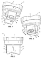
- Figs. 1-7 illustrate a gas sensor 10.
- the gas sensor 10 includes a sensor housing 14 and a sensing element 18 ( Fig. 7 ) disposed within the sensor housing 14.
- the sensing element 18 is an oxygen sensor, although other types of sensing elements 18 are also possible.
- the sensing element 18 defines an axis 22, and includes a distal end 26.
- the gas sensor 10 further includes a sensor protection device 30.
- the protection device 30 is coupled to the housing 14 and at least partially surrounds the distal end 26 of the sensing element 18.
- the protection device 30 includes a first, outer member 34 and a second, inner member 38.
- the inner member 38 is disposed within the outer member 34, and the distal end 26 of the sensing element is disposed within the inner member 38.
- the inner member 38 is coupled to the housing 14, and the outer member 34 is coupled to both the housing 14 and to the inner member 38.
- one or more of the outer member 34 and the inner member 38 are integrally formed with the housing 14 and/or with each other.
- one or more of the outer member 34 and the inner member 38 are removably coupled with the housing 14.
- the outer member 34 has a generally rectangular cross-sectional shape in a plane perpendicular to the axis 22. As will be discussed further below, this generally rectangular cross-sectional shape facilitates the desired gas flow through the protection device 30.
- the outer member 34 includes a first sidewall 42 having a generally rectangular gas inlet 46, a second, opposite sidewall 50 having a generally rectangular gas outlet 54, and an open channel 58 extending generally perpendicular to the axis 22 between the gas inlet 46 and the gas outlet 54.
- the gas inlet 46 and the gas outlet 54 are approximately 180 degrees apart from one another on the gas sensor 10.
- the outer member 34 also includes two sidewalls 60, 61 that are generally perpendicular to the sidewalls 42, 50, and that do not include any gas inlets or gas outlets.
- the sidewalls 42, 50 are generally parallel to one another, and the sidewalls 60, 61 are generally parallel to one another.
- Other constructions include different shapes for the gas inlet 46 and the gas outlet 54. In some constructions more than one gas inlet 46 and/or gas outlet 54 are provided.
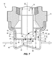
- the open channel 58 is formed in part by an end wall 62 of the outer member 34.
- the end wall 62 extends between the sidewalls 42, 50, and has an angled, non-linear profile that forms converging and diverging cross-sections within the channel 58.
- the channel 58 has a first cross-sectional area 66 taken along a plane parallel to the axis 22, a second cross-sectional area 70 taken along a plane parallel to the axis 22, and a third cross-sectional area 74 taken along a plane parallel to the axis 22.
- the third cross-sectional area 74 is disposed between the first and second cross-sectional areas 66, 70, and is smaller than both the first and second cross-sectional areas 62, 66.
- the third cross-sectional area 74 is the smallest cross-sectional area through which gas moves in the channel 58.
- the third cross-sectional area 74 is disposed generally in a middle portion of the channel 58.
- Other constructions include different sizes and shapes of cross-sectional areas than those illustrated.
- a main flow of gas 78 enters the protection device 30 through the gas inlet 46 and is manipulated by Bernoulli's Principle of flow within the channel 58, such that the gas flow 78 passing through the outer member 34 experiences lower pressure and higher velocity in the third cross-sectional area 74 as compared with both the first and second cross-sectional areas 66, 70.
- the outer member 34 converges in cross-sectional area from the first cross-sectional area 66 to the third cross-sectional area 74, and diverges in cross-sectional area from the third cross-sectional area 74 to the second cross-sectional area 70.
- the velocity of the gas flow 78 increases with a simultaneous decrease in pressure.
- the velocity of the gas flow 78 decreases and the pressure increases.
- the majority of the gas flow 78 between the gas inlet 46 and the gas outlet 54 passes through the protection device 30 in a direction perpendicular to the axis 22 without influencing the sensing element 18. Because of the generally rectangular cross-sectional structure of the outer member 34 and the locations of the gas inlet 46 and the gas outlet 54, the gas flow 78 is a generally linear gas flow through the protection device 30.
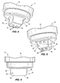
- the inner member 38 has a generally rectangular cross-sectional shape in a plane perpendicular to the axis 22. As will be discussed further below, this generally rectangular cross-sectional shape also facilitates the desired gas flow through the protection device 30.
- the inner member 38 includes a first sidewall 82 that is coupled directly to the sidewall 42 of the outer member 34 adjacent the gas inlet 46, and does not include any gas inlets or gas outlets.
- the inner member 38 further includes a second, opposite sidewall 86 that includes a plurality of gas inlets 90 ( Figs. 5 and 7 ).
- the inner member also includes two sidewalls 92, 93 that are generally perpendicular to the sidewalls 82, 86, and that do not include any gas inlets or gas outlets.
- the sidewalls 82, 86 are generally parallel to one another, and the sidewalls 93, 93 are generally parallel to one another.
- the inner member 38 further includes an end wall 94 disposed between the sidewalls 82, 86.
- the end wall 94 includes a plurality of gas outlets 98. As illustrated in Fig. 7 , the gas outlets 98 are disposed between the third cross-sectional area 74 and the gas outlet 54, generally in a middle portion of the open channel 58 and downstream of the third cross-sectional area 74.
- Other constructions include different numbers, shapes, patterns, and locations of gas inlets 90 and gas outlet 94 other than that illustrated.
- the protection device 30 also includes a chamber 102 formed between the sidewall 86 and the sidewall 50.
- the chamber 102 extends generally parallel to the axis 22, and is in direct fluid communication with both the channel 58 and the gas inlets 90.
- a portion 106 of the gas flow 78 (as illustrated by the smaller, circulating arrows in Fig. 7 ) is induced (e.g., drawn up) into the chamber 102 toward the gas inlets 90.
- This portion 106 circulates through the gas inlets 90 in a direction generally perpendicular to the axis 22, over the distal end 26 of the sensing element 18, and then out through the gas outlets 98 in a direction generally parallel to the axis 22 and back into the channel 58, rejoining the main gas flow 78.
- Fig. 7 because of the higher pressure of the gas flow 78 at the gas outlet 54 as compared to the third cross-sectional area 74, a portion 106 of the gas flow 78 (as illustrated by the smaller, circulating arrows in Fig. 7 ) is induced (e.g., drawn up) into the chamber 102 toward the gas inlets 90.
- This portion 106 circulates through the gas inlets 90 in a direction generally perpendicular to the axis 22,
- the circulating portion 106 creates a sampling of gas across the sensing element 18.
- the momentum of the contaminant mass in the main gas flow 78 keeps the contaminant mass moving within channel 58 in a direction generally perpendicular to the axis 22, such that all (or at least a substantial portion) of the contaminant mass in the main gas flow 78 does not move into the circulating portion 106 and does not enter the gas inlets 90, thereby protecting the sensing element 18 from damage or contamination from the contaminant mass in the main gas flow 78.
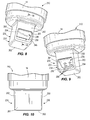
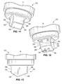
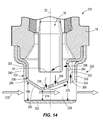
- Figs. 8-14 illustrate a gas sensor 210 having an outer member 234 with an end wall 262 and an inner member 238 with an end wall 294.
- the gas sensor 210 is identical to the gas sensor 10, with the exception of the geometry of the end walls 262 and 294.
- Like parts have been given like reference numbers, while similar parts have been given reference numbers that are increased by 200.
- the end wall 262 is generally flat or planar, and the end wall 294 includes a non-linear profile, in contrast to Fig. 7 where the end wall 94 is generally flat or planar, and the end wall 62 has the non-linear profile.
- the converging and diverging cross-sectional areas of the protection device 230 are formed by the non-linear profile of the end wall 294 on the inner member 238.
- the converging and diverging cross-sectional areas of the protection device 30 are formed by the non-linear profile of the end wall 62 on the outer member 34.
- the converging and diverging cross-sectional areas of the protection devices are formed with both the inner and outer protection devices having non-linear profiles (e.g., with both end walls having non-linear profiles).
- the converging and diverging cross-sectional areas are formed by having a non-linear profile in a different plane around a direction of the gas flow 78 other than that illustrated in Figs. 1-14 (e.g., a construction with one or more sidewalls of the outer and inner members having a non-linear profile as opposed to one or more end walls of the outer and inner members having a non-linear profile).
- the protection device 230 includes an open channel 258 with a first cross-sectional area 266 taken along a plane parallel to the axis 22, a second cross-sectional area 270 taken along a plane parallel to the axis 22, and a third cross-sectional area 274 taken along a plane parallel to the axis 22.
- the inner member 238 includes gas outlets 298 that are disposed downstream of the third cross-sectional area 274 and are protected, at least in part, by the non-linear shape of the end wall 294 from a direct gas flow 278 that initially enters the outer member 234.
- the claimed and/or described gas sensor wherein the gas inlet has a generally rectangular shape and the gas outlet has a generally rectangular shape.
- a gas sensor comprising: a sensor housing; a sensing element disposed within the sensor housing, the sensing element having a distal end and defining an axis; and a sensor protection device coupled to the sensor housing and at least partially surrounding the distal end of the sensing element, the sensor protection device including a first member coupled to the housing, the first member having a generally rectangular cross-sectional shape in a plane perpendicular to the axis, wherein the first member includes a first sidewall having a gas inlet and a second, opposite sidewall having a gas outlet, and at least partially defines an open channel extending between the gas inlet and the gas outlet, the open channel having a first cross-sectional area, a second cross-sectional area, and a third cross-sectional area between the gas inlet and the gas outlet, the third cross-sectional area being smaller than both the first and second cross-sectional areas such that gas passing through the outer member experiences lower pressure and higher velocity in the third cross-sectional area as compared with both the first and second cross-section
- the protection device includes a chamber disposed between the second sidewall of the first member and the second sidewall of the second member, the chamber in fluid communication with both the open channel and the gas inlet of the second member.
- the first member includes an end wall disposed between the first and second sidewalls of the first member, the end wall having a non-linear profile.
Landscapes
- Chemical & Material Sciences (AREA)
- Health & Medical Sciences (AREA)
- Life Sciences & Earth Sciences (AREA)
- Engineering & Computer Science (AREA)
- Physics & Mathematics (AREA)
- General Physics & Mathematics (AREA)
- Combustion & Propulsion (AREA)
- Pathology (AREA)
- Analytical Chemistry (AREA)
- Biochemistry (AREA)
- General Health & Medical Sciences (AREA)
- Immunology (AREA)
- Food Science & Technology (AREA)
- Medicinal Chemistry (AREA)
- Electrochemistry (AREA)
- Chemical Kinetics & Catalysis (AREA)
- Molecular Biology (AREA)
- Emergency Medicine (AREA)
- Measuring Oxygen Concentration In Cells (AREA)
- Investigating Or Analyzing Materials By The Use Of Electric Means (AREA)
Applications Claiming Priority (2)
| Application Number | Priority Date | Filing Date | Title |
|---|---|---|---|
| US201361879403P | 2013-09-18 | 2013-09-18 | |
| US14/155,909 US9488628B2 (en) | 2013-09-18 | 2014-01-15 | Gas sensor protection device and method |
Publications (1)
| Publication Number | Publication Date |
|---|---|
| EP2851680A1 true EP2851680A1 (fr) | 2015-03-25 |
Family
ID=51302922
Family Applications (1)
| Application Number | Title | Priority Date | Filing Date |
|---|---|---|---|
| EP14180911.1A Withdrawn EP2851680A1 (fr) | 2013-09-18 | 2014-08-14 | Capteur de gaz avec un dispositif de protection |
Country Status (3)
| Country | Link |
|---|---|
| US (1) | US9488628B2 (fr) |
| EP (1) | EP2851680A1 (fr) |
| CN (1) | CN104459028B (fr) |
Families Citing this family (9)
| Publication number | Priority date | Publication date | Assignee | Title |
|---|---|---|---|---|
| JP6369496B2 (ja) * | 2015-09-17 | 2018-08-08 | 株式会社デンソー | ガスセンサ |
| US10392999B2 (en) * | 2016-10-11 | 2019-08-27 | Ford Global Technologies, Llc | Method and system for exhaust particulate matter sensing |
| KR102374332B1 (ko) * | 2017-03-03 | 2022-03-16 | 엘지전자 주식회사 | 듀얼 히터 가스센서 모듈 |
| JP6904881B2 (ja) * | 2017-10-27 | 2021-07-21 | 日本特殊陶業株式会社 | ガスセンサ |
| CN109580237B (zh) * | 2018-12-11 | 2020-12-08 | 天津大学 | 一种防止缸压传感器失效的装置 |
| CN112255366B (zh) * | 2019-07-22 | 2024-12-31 | 海湾安全技术有限公司 | 具有防水能力的气体探测器 |
| JP7438077B2 (ja) * | 2020-10-07 | 2024-02-26 | 日本特殊陶業株式会社 | ガスセンサ |
| EP4279917A1 (fr) * | 2022-05-19 | 2023-11-22 | Honeywell International Inc. | Dispositif de détection d'émissions avec une conception de profil d'écoulement qui améliore le taux de réponse et la sensibilité |
| CN117092283A (zh) * | 2022-05-19 | 2023-11-21 | 霍尼韦尔国际公司 | 具有改善响应速率和灵敏度的流动剖面设计的排放检测设备 |
Citations (4)
| Publication number | Priority date | Publication date | Assignee | Title |
|---|---|---|---|---|
| US5880353A (en) * | 1996-03-06 | 1999-03-09 | Robert Bosch Gmbh | Gas sensor |
| US6279376B1 (en) * | 1998-09-28 | 2001-08-28 | Denso Corporation | Gas sensor for vehicle engine having a double-pipe cover |
| US20040144645A1 (en) * | 2003-01-20 | 2004-07-29 | Kohei Yamada | Gas sensor with improved structure of protective cover |
| DE102012017076A1 (de) * | 2012-08-29 | 2013-03-14 | Daimler Ag | Abgassensor |
Family Cites Families (12)
| Publication number | Priority date | Publication date | Assignee | Title |
|---|---|---|---|---|
| JP3311103B2 (ja) * | 1993-09-16 | 2002-08-05 | 本田技研工業株式会社 | 船外機の排気ガス採取装置 |
| JP3829026B2 (ja) | 1999-04-19 | 2006-10-04 | 日本碍子株式会社 | ガスセンサ |
| US7360414B2 (en) | 2003-07-14 | 2008-04-22 | Robert Bosch Gmbh | Device for determining at least one parameter of a medium flowing in a conduit and having a separation opening in the bypass passage |
| JP4725494B2 (ja) | 2006-04-27 | 2011-07-13 | 株式会社デンソー | ガスセンサ |
| JP2008058297A (ja) | 2006-08-04 | 2008-03-13 | Ngk Spark Plug Co Ltd | ガスセンサ |
| JP5069941B2 (ja) | 2006-09-14 | 2012-11-07 | 日本特殊陶業株式会社 | ガスセンサ |
| US7827849B2 (en) | 2006-11-02 | 2010-11-09 | Ngk Spark Plug Co., Ltd. | Gas sensor |
| JP4886006B2 (ja) * | 2009-05-11 | 2012-02-29 | 日本特殊陶業株式会社 | ガスセンサユニット |
| JP5254154B2 (ja) | 2009-08-17 | 2013-08-07 | 日本碍子株式会社 | ガスセンサ |
| JP4856751B2 (ja) | 2009-11-27 | 2012-01-18 | 日本碍子株式会社 | ガス濃度検出センサー |
| JP5508462B2 (ja) * | 2011-06-14 | 2014-05-28 | 日本特殊陶業株式会社 | ガスセンサ |
| CN103207226B (zh) * | 2012-01-16 | 2015-08-05 | 日本特殊陶业株式会社 | 气体传感器 |
-
2014
- 2014-01-15 US US14/155,909 patent/US9488628B2/en not_active Expired - Fee Related
- 2014-08-14 EP EP14180911.1A patent/EP2851680A1/fr not_active Withdrawn
- 2014-09-16 CN CN201410471303.1A patent/CN104459028B/zh not_active Expired - Fee Related
Patent Citations (4)
| Publication number | Priority date | Publication date | Assignee | Title |
|---|---|---|---|---|
| US5880353A (en) * | 1996-03-06 | 1999-03-09 | Robert Bosch Gmbh | Gas sensor |
| US6279376B1 (en) * | 1998-09-28 | 2001-08-28 | Denso Corporation | Gas sensor for vehicle engine having a double-pipe cover |
| US20040144645A1 (en) * | 2003-01-20 | 2004-07-29 | Kohei Yamada | Gas sensor with improved structure of protective cover |
| DE102012017076A1 (de) * | 2012-08-29 | 2013-03-14 | Daimler Ag | Abgassensor |
Also Published As
| Publication number | Publication date |
|---|---|
| US9488628B2 (en) | 2016-11-08 |
| US20150075253A1 (en) | 2015-03-19 |
| CN104459028A (zh) | 2015-03-25 |
| CN104459028B (zh) | 2018-01-19 |
Similar Documents
| Publication | Publication Date | Title |
|---|---|---|
| US9488628B2 (en) | Gas sensor protection device and method | |
| US8206476B2 (en) | Cover for a diesel particulate filter | |
| WO2007140148A3 (fr) | Mélangeur à recyclage de gaz d'échappement | |
| EP2211104A3 (fr) | Système de refroidissement à effet Venturi | |
| EP3505732B1 (fr) | Dispositif d'échappement de moteur | |
| JP4748081B2 (ja) | 内燃機関の排気装置 | |
| CN103184917B (zh) | 废气处理设备 | |
| EP3126201B1 (fr) | Clapet anti-retour de dérivation et dispositifs venturi doté de celui-ci | |
| US20090183503A1 (en) | Exhaust apparatus | |
| WO2011129296A1 (fr) | Détecteur de gaz d'échappement | |
| US9574528B2 (en) | Exhaust gas recirculation adapter | |
| EP2410166B1 (fr) | Dispositif de mélange de gaz d'échappement avec air frais à renvoyer à un moteur à combustion | |
| US20160349227A1 (en) | PLUG-IN NOx SENSOR SNORKEL FOR READING OPTIMIZATION UNDER PACKAGING CONSTRAINTS | |
| JP5494068B2 (ja) | エンジンの排気装置 | |
| EP3540207B1 (fr) | Unité d'atténuation de bruit pour systèmes moteur | |
| CN104870990A (zh) | 用于内燃发动机的具有涡流的进入气体传感器 | |
| US9739237B2 (en) | Exhaust gas recirculation device | |
| US20080118347A1 (en) | Turbine engine diffusing exhaust muffler | |
| JP2006132373A (ja) | Egrガス混合装置 | |
| EP0837324A3 (fr) | Dispositif pour détecter la concentration de gaz | |
| US10408169B2 (en) | Exhaust gas recirculation mixer | |
| JP5736662B2 (ja) | 排気センサー | |
| US9581064B2 (en) | Truck provided with a device for lowering the temperature of exhaust gas | |
| US20190170034A1 (en) | Compact device for purification and recirculation of exhaust gas | |
| ITBO20130684A1 (it) | Collettore di aspirazione per un motore a combustione interna sovralimentato con intercooler integrato e provvisto di uno scambiatore di calore per un circuito egr ad alta pressione |
Legal Events
| Date | Code | Title | Description |
|---|---|---|---|
| PUAI | Public reference made under article 153(3) epc to a published international application that has entered the european phase |
Free format text: ORIGINAL CODE: 0009012 |
|
| 17P | Request for examination filed |
Effective date: 20140814 |
|
| AK | Designated contracting states |
Kind code of ref document: A1 Designated state(s): AL AT BE BG CH CY CZ DE DK EE ES FI FR GB GR HR HU IE IS IT LI LT LU LV MC MK MT NL NO PL PT RO RS SE SI SK SM TR |
|
| AX | Request for extension of the european patent |
Extension state: BA ME |
|
| R17P | Request for examination filed (corrected) |
Effective date: 20150925 |
|
| RBV | Designated contracting states (corrected) |
Designated state(s): AL AT BE BG CH CY CZ DE DK EE ES FI FR GB GR HR HU IE IS IT LI LT LU LV MC MK MT NL NO PL PT RO RS SE SI SK SM TR |
|
| RAP1 | Party data changed (applicant data changed or rights of an application transferred) |
Owner name: ROBERT BOSCH GMBH |
|
| 17Q | First examination report despatched |
Effective date: 20190307 |
|
| RAP1 | Party data changed (applicant data changed or rights of an application transferred) |
Owner name: ROBERT BOSCH GMBH |
|
| STAA | Information on the status of an ep patent application or granted ep patent |
Free format text: STATUS: THE APPLICATION HAS BEEN WITHDRAWN |
|
| 18W | Application withdrawn |
Effective date: 20200807 |