EP2851736A1 - Branche de lunettes - Google Patents
Branche de lunettes Download PDFInfo
- Publication number
- EP2851736A1 EP2851736A1 EP14176089.2A EP14176089A EP2851736A1 EP 2851736 A1 EP2851736 A1 EP 2851736A1 EP 14176089 A EP14176089 A EP 14176089A EP 2851736 A1 EP2851736 A1 EP 2851736A1
- Authority
- EP
- European Patent Office
- Prior art keywords
- leg
- legs
- temples
- temple
- decorative
- Prior art date
- Legal status (The legal status is an assumption and is not a legal conclusion. Google has not performed a legal analysis and makes no representation as to the accuracy of the status listed.)
- Withdrawn
Links
- 239000010437 gem Substances 0.000 claims description 7
- 229910001751 gemstone Inorganic materials 0.000 claims description 7
- 238000010409 ironing Methods 0.000 claims description 4
- 230000002093 peripheral effect Effects 0.000 claims description 3
- 210000002414 leg Anatomy 0.000 description 127
- 239000000463 material Substances 0.000 description 5
- 238000013461 design Methods 0.000 description 4
- 239000002184 metal Substances 0.000 description 4
- 238000005452 bending Methods 0.000 description 3
- 238000003780 insertion Methods 0.000 description 3
- 230000037431 insertion Effects 0.000 description 3
- 239000004033 plastic Substances 0.000 description 3
- 239000010432 diamond Substances 0.000 description 2
- 229910003460 diamond Inorganic materials 0.000 description 2
- 238000006073 displacement reaction Methods 0.000 description 2
- 239000005337 ground glass Substances 0.000 description 2
- 238000003754 machining Methods 0.000 description 2
- 238000004519 manufacturing process Methods 0.000 description 2
- 238000003801 milling Methods 0.000 description 2
- 239000004575 stone Substances 0.000 description 2
- 210000000689 upper leg Anatomy 0.000 description 2
- 230000015572 biosynthetic process Effects 0.000 description 1
- 238000011161 development Methods 0.000 description 1
- 230000018109 developmental process Effects 0.000 description 1
- 230000000694 effects Effects 0.000 description 1
- 239000011521 glass Substances 0.000 description 1
- 238000012986 modification Methods 0.000 description 1
- 230000004048 modification Effects 0.000 description 1
- 230000003287 optical effect Effects 0.000 description 1
- 229920001296 polysiloxane Polymers 0.000 description 1
- 230000000284 resting effect Effects 0.000 description 1
- 239000012815 thermoplastic material Substances 0.000 description 1
- 230000000007 visual effect Effects 0.000 description 1
Images

Classifications
-
- G—PHYSICS
- G02—OPTICS
- G02C—SPECTACLES; SUNGLASSES OR GOGGLES INSOFAR AS THEY HAVE THE SAME FEATURES AS SPECTACLES; CONTACT LENSES
- G02C5/00—Constructions of non-optical parts
- G02C5/14—Side-members
-
- G—PHYSICS
- G02—OPTICS
- G02C—SPECTACLES; SUNGLASSES OR GOGGLES INSOFAR AS THEY HAVE THE SAME FEATURES AS SPECTACLES; CONTACT LENSES
- G02C11/00—Non-optical adjuncts; Attachment thereof
- G02C11/02—Ornaments, e.g. exchangeable
-
- G—PHYSICS
- G02—OPTICS
- G02C—SPECTACLES; SUNGLASSES OR GOGGLES INSOFAR AS THEY HAVE THE SAME FEATURES AS SPECTACLES; CONTACT LENSES
- G02C5/00—Constructions of non-optical parts
- G02C5/14—Side-members
- G02C5/16—Side-members resilient or with resilient parts
-
- G—PHYSICS
- G02—OPTICS
- G02C—SPECTACLES; SUNGLASSES OR GOGGLES INSOFAR AS THEY HAVE THE SAME FEATURES AS SPECTACLES; CONTACT LENSES
- G02C5/00—Constructions of non-optical parts
- G02C5/14—Side-members
- G02C5/143—Side-members having special ear pieces
Definitions
- the invention relates to a temple for receiving interchangeable decorative elements according to the preamble of claim 1.
- spectacle frames which usually consist of two temples and a spectacle frame for holding the spectacle lenses, are sufficiently known from the prior art.
- this describes DE 20 2011 004 795 U1 a temple, in which the end of a temple is removable, so as to attach decorative elements on the temple can.
- DE 20 2011 004 795 U1 disclosed eyeglass temple easy replacement of decorative elements, but primarily only decorative elements can be plugged, which are at least partially formed ring-shaped and completely surround the temple. The use of gemstones or similar decorative elements is not possible in the described temple ironing.
- the DE 20 2010 016 675 U1 discloses, for example, a temples with a pivotable bracket stop and a strap end, in which a slot is provided in the longitudinal direction of the eyeglass temple, wherein the slot is formed open at its end facing the bracket stop.
- Decorative elements can be inserted into the slot.
- the disadvantage here is that the slot is open with folded eyeglass temple and an inserted decorative element is not sufficiently secured against eventual falling out.
- the object of the invention is to specify a spectacle arm whose optical appearance can be individually changed by the spectacle wearer in a particularly simple manner, preferably quickly and thereby user-friendly.
- the object is achieved on the basis of the features of the preamble of claim 1 by its characterizing features.
- the invention relates to a temples for interchangeable receiving jewelry elements comprising at least one decorative element, at least one at least one element receiving the jewelry element and a clip-on strap element on the temple end piece.
- the bracket member is tweezer-shaped and has a first and second leg, wherein the legs in a connection region ELId lake, resiliently communicate with each other and each have a connection region opposite, free leg end, said at least one decorative element between the first and second legs is received interchangeable, by clamping the at least one decorative element between the first and second legs of the tweezer-like bracket member by compressing the free leg ends and attaching the Bügelend Federationes on the two free leg ends of the compressed leg.
- At least one decorative element can be inserted particularly easily between the two legs.
- the jewelry element can be clamped between the legs and thus fixed.
- the temple end piece is attached from the free leg ends forth on the bracket element.
- the free leg ends and thus the legs are set and the jewelry element remains fixed in the press fit.
- the replacement of a decorative element by another decorative element is possible in a particularly simple and fast way.
- a one-piece, tweezer-shaped bracket element for example, a made of a plastic or metal flat material by a machining process, for example, be processed by milling.
- the two cantilevered legs can be produced on one side, the spring effect being achieved primarily by the material properties, in particular, for example, by bending properties of the flat material.
- two prefabricated legs can be fixedly connected to one another at the connection area, in particular welded.
- the two legs of the tweezer-shaped bracket element on each side facing the inside of each leg at least one recess for receiving a jewelry element, wherein the recesses are arranged in the leg inner sides opposite one another.
- the legs have on their leg inner sides a plurality of opposing recesses for receiving a plurality of decorative elements.
- recesses for receiving the decorative elements of the outwardly acting pressure on the legs of the leg inner sides which is generated by the inserted and clamped between the legs of the tweezer-like strap element decorative elements are reduced. The legs are thereby relieved and an unwanted bending of the legs is effectively counteracted.
- the recesses in the inner sides of the legs are particularly advantageously essentially round, in particular semicircular or alternatively substantially rectangular, in particular square.
- corresponding engagement portions are provided on the leg inner sides of the two legs, wherein the corresponding engagement portions are formed at least in sections for non-shift mesh.
- the corresponding, at least partially intermeshing engagement sections that the two legs of the tweezer-shaped bracket member are correctly positioned to each other in the closed state and no unnecessary and unwanted or even damaging tensile or compressive forces acting on the connecting portion of the legs.
- the corresponding engagement sections on the inner sides of the legs may be, for example, wave-shaped, zigzag-shaped or serrated. Under wave, zigzag or jagged is also understood in the present case that the leg inner sides in the region of the engaging portions are curved or wavy, the vibrations or waves may have, for example, a sinusoidal, rectangular or triangular shape, of course always under the proviso in that the engagement sections can mesh at least in sections.
- the engagement portions may also be formed such that, for example, in the leg inner side of the first leg, a recess and in the leg inner side of the second leg a projection corresponding to the shape of the recess is formed, which can engage in the recess.
- the first and the second leg of the tweezer-shaped bracket member are the same length.
- the two free leg ends of this preferred embodiment are in contact with one another. Both free leg ends are accommodated in the plugged temple end piece.
- the first leg can also be extended in the direction of a main axis of the eyeglass temple relative to the second leg.
- the second leg In the closed state of the tweezer-type bracket element is the free leg end of the second leg in contact with the first leg and in a central portion of the first leg.
- the second leg may be extended in the direction of the main axis of the eyeglass temple relative to the first leg.
- both free leg ends are received in the plugged temple end piece.
- the leg extended in the direction of the main axis can have a support section, wherein the support section with the free leg end is completely accommodated by the strap end piece.
- the support portion of the extended in the direction of the main axis leg adapts to the temple end piece and assumes, for example, the predetermined curved shape of the temple end piece.
- the attachable temple end piece is formed substantially sleeve-shaped and closed on one side, wherein the sleeve-shaped Bügelend Swiss has an inner wall, an outer peripheral surface and a substantially circular cross-section.
- the closed end or the closed end opposite open end of the sleeve-shaped Bügelend thoroughlyes can be considered in the present case as Einsteckende or Aufsteckseite.
- a projecting shoulder is formed, which constitutes a contact surface for the free leg end of the shorter leg.
- the temple end piece is preferably made of plastic, in particular of a thermoplastic material or of silicone. Alternatively, however, the temple end piece may also be made of a rubber or a metal.
- each jewelery element consists of a gem attached to a holder, preferably a ground glass stone, a rhinestone or a gemstone, in particular a diamond, wherein provided in the one substantially H-shaped cross-section holder having a circumferential groove for engaging the leg inner sides of the yoke element is.
- the FIG. 1 schematically shows a temples 1 with recorded decorative elements 14 in a lateral view.
- the temple 1 consists of a bracket element 2 with accommodated decorative elements 14 and a plugged onto the bracket element 2 strap end piece 4, wherein the bracket element 2 and the temple end piece 4 in the direction of a longitudinal axis LA of the eyeglass temple 1 connect longitudinally together.
- the one-sided closed temple end piece 4 has a substantially round cross-section and is formed like a sleeve.
- the closed end or the closed end opposite the temple end piece 4 has an open end, wherein the temple end piece 4 is pushed or plugged forward with this also known as insertion or Aufsteckseite open end on the bracket element 2.
- the plugged Bügelend Georgia 4 is used, inter alia, to rest the eyeglass temple 1 on the ear of a spectacle wearer.
- a spectacle frame preferably comprises two such eyeglass temple 1, which are articulated either directly or indirectly laterally on a spectacle frame.
- the stirrup element 2 is designed like a tweezer and consists of a first and a second leg 2.1, 2.2.
- the two legs 2.1, 2.2 are in a connecting region 2 'on one side, resiliently connected to each other.
- the bracket made of metal 2 is formed in one piece and is made by a machining process of a flat material.
- Each leg 2.1, 2.2 has a connection region 2 'opposite, free leg end 5, 6 (in the FIG. 1 not shown, see FIG. 2a ), wherein the free leg ends 5, 6 are received in the temple end piece 4.
- the jewelry elements 14 are clamped between the two legs 2.1, 2.2 and are thus fixed to the temple 1.
- three individual decorative elements 14 between the two legs 2.1, 2.2 of the bracket element 2 are exemplified.
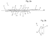
- FIG. 2a schematically illustrated tweezer-type bracket element 2 with a first and a second leg 2.1, 2.2 is the first leg 2.1 extended in comparison to the second leg 2.2 in the direction of the longitudinal axis LA of the temple piece 1 and has a support portion 3.
- the two legs 2.1, 2.2 are connected in a connecting region 2 'on one side and each have on the connection region 2' opposite side each have a free leg end 5, 6.
- Each of the two legs 2.1, 2.2 has a leg inner side 7, 8 and one of respective leg inner side 7, 8 opposite leg outer side 11, 12, wherein the leg inner sides 7, 8 of the two legs 2.1, 2.2 facing each other.
- the two legs 2.1, 2.2 can be moved towards each other and the tweezer-type bracket element 2 are brought into a closed state.
- the free end 6 of the second leg 2.2 is in contact with the support section 3 first leg 2.1 (see FIG. 3 ).
- leg inner sides 7, 8 of the two legs 2.1, 2.2 corresponding engaging portions 10 are formed, wherein the corresponding engaging portions 10 are formed in the closed state of the bracket element 2 at least partially so for non-shift mesh that a mutual Displacement of the two legs 2.1, 2.2 is prevented in the direction of the longitudinal axis of the eyeglass temple 1.
- the leg inner sides 7, 8 are corrugated in the region of the engagement portions 10, wherein the waves have a substantially sinusoidal-like shape.
- each leg 2.1, 2.2 on its inner side leg 7,8 each having three recesses 9.
- the recesses 9 are arranged such that each two recesses 9 are opposite and are provided for receiving a decorative element 14.
- FIG. 2b shows a section through a decorative element 14, which consists of a holder 16 and a fixed in the holder 16 gemstone 15, for example, a ground glass stone, a rhinestone or a gemstone, in particular a diamond exists.
- the holder 16 preferably made of plastic or of a metal, has a substantially H-shaped cross-section with a peripheral groove 17 for the engagement of the legs 2.1, 2.2 of the tweezer-type bracket element 2.
- each decorative element 14 is inserted from the free ends 5, 6 forth between the legs 2.1, 2.2, that the leg inner sides 7, 8 engage in the circumferential groove 17 of the holder 16 of the decorative element 14.
- the decorative element 14 is pushed further in the direction of the connection region 2 'to the desired position and introduced into recesses 9. This can also be understood as locking the jewelry elements 14 in the recesses 9.
- the pressure generated by the jewelry elements 14 on the legs 2.1, 2.2 of the leg inner sides 7, 8 ago reduced towards the outside, on the other hand it is also ensured that the decorative elements 14 in the direction of Longitudinal axis LA of the eyeglass temple 1 does not slip automatically or undesirably.
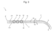
- FIG. 3 is a temple 1 consisting of the bracket element 2 of FIG. 2a and three decorative elements according to the FIG. 2b shown in a side view.
- the bracket member 2 of the temple piece 1 three decorative elements 14 are added, the jewelry elements 14 as already described above from the free leg ends 5, 6 forth between the legs 2.1, 2.2 are inserted.
- the two legs 2.1, 2.2 are moved toward each other and brought the tweezer-like bracket element 2 in a closed state.
- the free end 6 of the second leg 2.2 is in contact with the support section 3 of the first leg 2.1.
- the temple end piece 4 While maintaining the slight pressure on the outer sides of the legs 11, 12, namely under further action of the closing pressure, the temple end piece 4, again from the free leg ends 5, 6 ago, attached to the bracket element 2 in such a way that both free leg ends 5, 6 and the support section 3 of the first leg 2.1, which is extended relative to the second leg 2.2 in the direction of the longitudinal axis LA, is received by the temple end piece 4.
- the temple end piece 4 In order to prevent the temple end piece 4 is pushed too far on the bracket element and thereby any damage caused by bending on one of the two legs 2.1, 2.2, have the first and second legs 2.1, 2.2 at their leg outer sides 11, 12 for the facilitated handling one shoulder each 13 (see also FIG.
- the legs 2.1, 2.2 are fixed and fixed.
- the accommodated between the legs 2.1, 2.2 jewelery elements 14 are characterized in the press fit and are also sufficiently fixed and secured.
- the support section 3 of the opposite side of the second leg 2.2 in the direction of the longitudinal axis LA first leg 2.1 adapts by attaching the Bügelend thoroughlyes 4 substantially to the predetermined shape of the Bügelend thoroughlyes 4 and takes for example the preferred for resting on the ear of a spectacle wearer curved shape at.
- the plugged end piece 4 To replace the jewelry elements 14, the plugged end piece 4 must first be removed or withdrawn, whereby the tweezer-like bracket element 2 by the resilient connection in the connection area 2 'automatically in the as in the FIG. 2a shown opened state passes.
- the tweezer-type ironing element 2 By light Pushing apart of the two legs 2.1, 2.2 or by a possible under appropriate force pushing out of the jewelry elements 14 from the recesses 9, the tweezer-type ironing element 2 can be slightly more open, so that the recorded decorative elements 14 can be pushed out and removed and optionally replaced by others can.
Landscapes
- Physics & Mathematics (AREA)
- Health & Medical Sciences (AREA)
- General Physics & Mathematics (AREA)
- Ophthalmology & Optometry (AREA)
- Optics & Photonics (AREA)
- Adornments (AREA)
Applications Claiming Priority (1)
| Application Number | Priority Date | Filing Date | Title |
|---|---|---|---|
| DE202013104337U DE202013104337U1 (de) | 2013-09-23 | 2013-09-23 | Brillenbügel |
Publications (1)
| Publication Number | Publication Date |
|---|---|
| EP2851736A1 true EP2851736A1 (fr) | 2015-03-25 |
Family
ID=49547423
Family Applications (1)
| Application Number | Title | Priority Date | Filing Date |
|---|---|---|---|
| EP14176089.2A Withdrawn EP2851736A1 (fr) | 2013-09-23 | 2014-07-08 | Branche de lunettes |
Country Status (2)
| Country | Link |
|---|---|
| EP (1) | EP2851736A1 (fr) |
| DE (1) | DE202013104337U1 (fr) |
Cited By (3)
| Publication number | Priority date | Publication date | Assignee | Title |
|---|---|---|---|---|
| USD789441S1 (en) | 2015-06-26 | 2017-06-13 | Shorelys, Llc | Fashion accessory |
| US9946096B2 (en) | 2015-06-26 | 2018-04-17 | Shorelys, Llc | Decorative attachment for eyewear temple |
| US20210191150A1 (en) * | 2018-05-15 | 2021-06-24 | Masato Tsuchiya | Eyeglasses and eyeglasses support member |
Families Citing this family (1)
| Publication number | Priority date | Publication date | Assignee | Title |
|---|---|---|---|---|
| USD912129S1 (en) * | 2019-08-30 | 2021-03-02 | Cartier International Ag | Spectacles |
Citations (6)
| Publication number | Priority date | Publication date | Assignee | Title |
|---|---|---|---|---|
| JPH11133362A (ja) * | 1997-10-30 | 1999-05-21 | Masunaga Megane Kk | 眼鏡のインレイ装飾機構 |
| FR2912228A1 (fr) * | 2007-02-07 | 2008-08-08 | Tand M Sarl | Lunettes a branches modulables |
| DE202010007862U1 (de) * | 2010-06-11 | 2010-08-26 | Proksch, Wolfgang | Brillengestell |
| DE202010016675U1 (de) | 2010-12-16 | 2011-03-24 | Tom's Design Gmbh | Brillenbügel |
| DE202011004795U1 (de) | 2011-04-02 | 2011-12-14 | Nigura Metzler Optics International Gmbh | Abnehmbares Brillen-Bügelende |
| WO2012117369A2 (fr) * | 2011-03-03 | 2012-09-07 | Zaketac S.R.L. | Monture de lunettes |
-
2013
- 2013-09-23 DE DE202013104337U patent/DE202013104337U1/de not_active Expired - Lifetime
-
2014
- 2014-07-08 EP EP14176089.2A patent/EP2851736A1/fr not_active Withdrawn
Patent Citations (6)
| Publication number | Priority date | Publication date | Assignee | Title |
|---|---|---|---|---|
| JPH11133362A (ja) * | 1997-10-30 | 1999-05-21 | Masunaga Megane Kk | 眼鏡のインレイ装飾機構 |
| FR2912228A1 (fr) * | 2007-02-07 | 2008-08-08 | Tand M Sarl | Lunettes a branches modulables |
| DE202010007862U1 (de) * | 2010-06-11 | 2010-08-26 | Proksch, Wolfgang | Brillengestell |
| DE202010016675U1 (de) | 2010-12-16 | 2011-03-24 | Tom's Design Gmbh | Brillenbügel |
| WO2012117369A2 (fr) * | 2011-03-03 | 2012-09-07 | Zaketac S.R.L. | Monture de lunettes |
| DE202011004795U1 (de) | 2011-04-02 | 2011-12-14 | Nigura Metzler Optics International Gmbh | Abnehmbares Brillen-Bügelende |
Cited By (3)
| Publication number | Priority date | Publication date | Assignee | Title |
|---|---|---|---|---|
| USD789441S1 (en) | 2015-06-26 | 2017-06-13 | Shorelys, Llc | Fashion accessory |
| US9946096B2 (en) | 2015-06-26 | 2018-04-17 | Shorelys, Llc | Decorative attachment for eyewear temple |
| US20210191150A1 (en) * | 2018-05-15 | 2021-06-24 | Masato Tsuchiya | Eyeglasses and eyeglasses support member |
Also Published As
| Publication number | Publication date |
|---|---|
| DE202013104337U1 (de) | 2013-10-08 |
Similar Documents
| Publication | Publication Date | Title |
|---|---|---|
| DE3249790C2 (de) | Brillengestell mit Verbindungsmechanismus zwischen Fassungsteil und Bügeln | |
| DE202004007224U1 (de) | Brillengestell | |
| DE69700823T2 (de) | Scharnier für Brillenbügel mit einem Nockeneinsatz der zwei zueinander senkrechte aneinandergrenzende Oberflächen aufweist | |
| DE2204504A1 (de) | Fingerring | |
| DE19850863A1 (de) | Mittelteil einer Vollrandfassung für eine Brille | |
| EP2851736A1 (fr) | Branche de lunettes | |
| DE69918307T2 (de) | Modulare lesebrille | |
| EP2226672B1 (fr) | Monture de lunettes | |
| WO2011107410A1 (fr) | Paire de lunettes | |
| AT508941B1 (de) | Brille | |
| EP3726280A1 (fr) | Monture de lunettes avec éléments de charnière à clip et branches interchangeables | |
| AT408303B (de) | Halterung für einen schmuckstein | |
| DE202012006528U1 (de) | Brillengestell | |
| EP1875301B1 (fr) | Plaquette pour des lunettes | |
| EP1785763B1 (fr) | Branche de lunettes, et lunettes comprenant une telle branche | |
| DE202011052167U1 (de) | Aufbau einer Brille | |
| DE10334712A1 (de) | Adapter für einen Schmuckring | |
| WO2014090972A1 (fr) | Monture et branches de lunettes | |
| DE69935121T2 (de) | Herstellungsverfahren für brillen und nach diesem verfahren hergestellte brille | |
| AT521327B1 (de) | Brillengestell | |
| DE9417434U1 (de) | Schließe für Schmuckwaren | |
| AT526341A4 (de) | Fassung für Schmuckgegenstände | |
| AT509062A4 (de) | Brillenbügel | |
| DE102017000687A1 (de) | Brillenbügel und Brillengestell | |
| DE202023104186U1 (de) | Ohrschmuck |
Legal Events
| Date | Code | Title | Description |
|---|---|---|---|
| PUAI | Public reference made under article 153(3) epc to a published international application that has entered the european phase |
Free format text: ORIGINAL CODE: 0009012 |
|
| 17P | Request for examination filed |
Effective date: 20140708 |
|
| AK | Designated contracting states |
Kind code of ref document: A1 Designated state(s): AL AT BE BG CH CY CZ DE DK EE ES FI FR GB GR HR HU IE IS IT LI LT LU LV MC MK MT NL NO PL PT RO RS SE SI SK SM TR |
|
| AX | Request for extension of the european patent |
Extension state: BA ME |
|
| STAA | Information on the status of an ep patent application or granted ep patent |
Free format text: STATUS: THE APPLICATION IS DEEMED TO BE WITHDRAWN |
|
| 18D | Application deemed to be withdrawn |
Effective date: 20150926 |