EP2851759A1 - Verfahren und System zur adaptiven Ausgleichssteuerung der verbleibenden Lebensdauer eines Motors in einem mehrmotorigen System - Google Patents
Verfahren und System zur adaptiven Ausgleichssteuerung der verbleibenden Lebensdauer eines Motors in einem mehrmotorigen System Download PDFInfo
- Publication number
- EP2851759A1 EP2851759A1 EP14182715.4A EP14182715A EP2851759A1 EP 2851759 A1 EP2851759 A1 EP 2851759A1 EP 14182715 A EP14182715 A EP 14182715A EP 2851759 A1 EP2851759 A1 EP 2851759A1
- Authority
- EP
- European Patent Office
- Prior art keywords
- engine
- engines
- hot gas
- continuously
- real
- Prior art date
- Legal status (The legal status is an assumption and is not a legal conclusion. Google has not performed a legal analysis and makes no representation as to the accuracy of the status listed.)
- Granted
Links
- 238000000034 method Methods 0.000 title claims abstract description 38
- 230000003044 adaptive effect Effects 0.000 title 1
- 230000015556 catabolic process Effects 0.000 claims abstract description 68
- 238000006731 degradation reaction Methods 0.000 claims abstract description 68
- 230000007246 mechanism Effects 0.000 claims abstract description 66
- 238000004458 analytical method Methods 0.000 claims description 7
- 238000004891 communication Methods 0.000 claims description 7
- 230000001747 exhibiting effect Effects 0.000 claims 3
- 230000006870 function Effects 0.000 description 26
- 230000036541 health Effects 0.000 description 6
- 238000002485 combustion reaction Methods 0.000 description 5
- 239000000446 fuel Substances 0.000 description 5
- 238000010586 diagram Methods 0.000 description 4
- 239000000203 mixture Substances 0.000 description 4
- 230000009471 action Effects 0.000 description 3
- 230000005540 biological transmission Effects 0.000 description 3
- 230000006866 deterioration Effects 0.000 description 3
- 230000002542 deteriorative effect Effects 0.000 description 3
- 238000009877 rendering Methods 0.000 description 3
- 238000005516 engineering process Methods 0.000 description 1
- 239000004973 liquid crystal related substance Substances 0.000 description 1
- 230000004044 response Effects 0.000 description 1
- 230000002123 temporal effect Effects 0.000 description 1
- 239000010409 thin film Substances 0.000 description 1
Images


Classifications
-
- B—PERFORMING OPERATIONS; TRANSPORTING
- B64—AIRCRAFT; AVIATION; COSMONAUTICS
- B64C—AEROPLANES; HELICOPTERS
- B64C27/00—Rotorcraft; Rotors peculiar thereto
- B64C27/04—Helicopters
-
- F—MECHANICAL ENGINEERING; LIGHTING; HEATING; WEAPONS; BLASTING
- F02—COMBUSTION ENGINES; HOT-GAS OR COMBUSTION-PRODUCT ENGINE PLANTS
- F02C—GAS-TURBINE PLANTS; AIR INTAKES FOR JET-PROPULSION PLANTS; CONTROLLING FUEL SUPPLY IN AIR-BREATHING JET-PROPULSION PLANTS
- F02C9/00—Controlling gas-turbine plants; Controlling fuel supply in air- breathing jet-propulsion plants
- F02C9/26—Control of fuel supply
- F02C9/28—Regulating systems responsive to plant or ambient parameters, e.g. temperature, pressure, rotor speed
-
- F—MECHANICAL ENGINEERING; LIGHTING; HEATING; WEAPONS; BLASTING
- F02—COMBUSTION ENGINES; HOT-GAS OR COMBUSTION-PRODUCT ENGINE PLANTS
- F02C—GAS-TURBINE PLANTS; AIR INTAKES FOR JET-PROPULSION PLANTS; CONTROLLING FUEL SUPPLY IN AIR-BREATHING JET-PROPULSION PLANTS
- F02C9/00—Controlling gas-turbine plants; Controlling fuel supply in air- breathing jet-propulsion plants
- F02C9/26—Control of fuel supply
- F02C9/42—Control of fuel supply specially adapted for the control of two or more plants simultaneously
-
- G—PHYSICS
- G05—CONTROLLING; REGULATING
- G05B—CONTROL OR REGULATING SYSTEMS IN GENERAL; FUNCTIONAL ELEMENTS OF SUCH SYSTEMS; MONITORING OR TESTING ARRANGEMENTS FOR SUCH SYSTEMS OR ELEMENTS
- G05B23/00—Testing or monitoring of control systems or parts thereof
- G05B23/02—Electric testing or monitoring
- G05B23/0205—Electric testing or monitoring by means of a monitoring system capable of detecting and responding to faults
- G05B23/0259—Electric testing or monitoring by means of a monitoring system capable of detecting and responding to faults characterized by the response to fault detection
- G05B23/0283—Predictive maintenance, e.g. involving the monitoring of a system and, based on the monitoring results, taking decisions on the maintenance schedule of the monitored system; Estimating remaining useful life [RUL]
-
- G—PHYSICS
- G05—CONTROLLING; REGULATING
- G05B—CONTROL OR REGULATING SYSTEMS IN GENERAL; FUNCTIONAL ELEMENTS OF SUCH SYSTEMS; MONITORING OR TESTING ARRANGEMENTS FOR SUCH SYSTEMS OR ELEMENTS
- G05B23/00—Testing or monitoring of control systems or parts thereof
- G05B23/02—Electric testing or monitoring
- G05B23/0205—Electric testing or monitoring by means of a monitoring system capable of detecting and responding to faults
- G05B23/0259—Electric testing or monitoring by means of a monitoring system capable of detecting and responding to faults characterized by the response to fault detection
- G05B23/0286—Modifications to the monitored process, e.g. stopping operation or adapting control
- G05B23/0294—Optimizing process, e.g. process efficiency, product quality
-
- B—PERFORMING OPERATIONS; TRANSPORTING
- B64—AIRCRAFT; AVIATION; COSMONAUTICS
- B64D—EQUIPMENT FOR FITTING IN OR TO AIRCRAFT; FLIGHT SUITS; PARACHUTES; ARRANGEMENT OR MOUNTING OF POWER PLANTS OR PROPULSION TRANSMISSIONS IN AIRCRAFT
- B64D45/00—Aircraft indicators or protectors not otherwise provided for
- B64D2045/0085—Devices for aircraft health monitoring, e.g. monitoring flutter or vibration
-
- F—MECHANICAL ENGINEERING; LIGHTING; HEATING; WEAPONS; BLASTING
- F05—INDEXING SCHEMES RELATING TO ENGINES OR PUMPS IN VARIOUS SUBCLASSES OF CLASSES F01-F04
- F05D—INDEXING SCHEME FOR ASPECTS RELATING TO NON-POSITIVE-DISPLACEMENT MACHINES OR ENGINES, GAS-TURBINES OR JET-PROPULSION PLANTS
- F05D2220/00—Application
- F05D2220/30—Application in turbines
- F05D2220/32—Application in turbines in gas turbines
- F05D2220/329—Application in turbines in gas turbines in helicopters
-
- F—MECHANICAL ENGINEERING; LIGHTING; HEATING; WEAPONS; BLASTING
- F05—INDEXING SCHEMES RELATING TO ENGINES OR PUMPS IN VARIOUS SUBCLASSES OF CLASSES F01-F04
- F05D—INDEXING SCHEME FOR ASPECTS RELATING TO NON-POSITIVE-DISPLACEMENT MACHINES OR ENGINES, GAS-TURBINES OR JET-PROPULSION PLANTS
- F05D2260/00—Function
- F05D2260/81—Modelling or simulation
-
- F—MECHANICAL ENGINEERING; LIGHTING; HEATING; WEAPONS; BLASTING
- F05—INDEXING SCHEMES RELATING TO ENGINES OR PUMPS IN VARIOUS SUBCLASSES OF CLASSES F01-F04
- F05D—INDEXING SCHEME FOR ASPECTS RELATING TO NON-POSITIVE-DISPLACEMENT MACHINES OR ENGINES, GAS-TURBINES OR JET-PROPULSION PLANTS
- F05D2270/00—Control
- F05D2270/01—Purpose of the control system
- F05D2270/11—Purpose of the control system to prolong engine life
-
- F—MECHANICAL ENGINEERING; LIGHTING; HEATING; WEAPONS; BLASTING
- F05—INDEXING SCHEMES RELATING TO ENGINES OR PUMPS IN VARIOUS SUBCLASSES OF CLASSES F01-F04
- F05D—INDEXING SCHEME FOR ASPECTS RELATING TO NON-POSITIVE-DISPLACEMENT MACHINES OR ENGINES, GAS-TURBINES OR JET-PROPULSION PLANTS
- F05D2270/00—Control
- F05D2270/01—Purpose of the control system
- F05D2270/13—Purpose of the control system to control two or more engines simultaneously
Definitions
- the present invention generally relates to remaining useful life analyses, and more particularly relates to a system and method for adaptively controlling the operation of a multi-engine system to maximize the remaining useful life of the engines while satisfying the demand load.
- Helicopters typically have two engines that are connected through a combiner transmission to share the load of the rotor. It is desirable to share the load equally between the two engines so that the engines are more likely to deteriorate at the same (or similar) pace, and impart less stress to the combiner transmission. It is even more desirable to manage the deterioration rates such that both engines reach their end of useful lives together. However, this is difficult to achieve unless one can measure the engine deterioration rate in real time. Helicopter engine controllers are typically configured to selectively implement one of a plurality load sharing control methods, and control logic that selects the control method. These control methods may include, for example, torque matching, a temperature matching, and a speed matching. With the torque matching method, measured engine torque is equalized, with the temperature matching method, measured engine temperatures are equalized, and with the speed matching method, measured engine speeds are equalized.
- the engines may deteriorate at a relatively rapid rate.
- the pilot utilizing the normal operational limits of the engines, is unable to perform a particular maneuver.
- the pilot may need to exceed the normal operational limits to perform the maneuver.
- the pilot may be unable to achieve a controlled descent due to lack of power and hence may wish to exceed the normal operational power limits in order to harness all of available engine power. Because such operations can rapidly increase the rate of engine deterioration, it would be useful to have some type of real-time engine condition assessment and management tool to assist the pilot in managing such deteriorating engine conditions. Unfortunately, no such tool is available.
- a method of adaptively managing a plurality of engines in a multi-engine system includes continuously, and in real-time, determining a plurality of different degradation mechanisms for each of the plurality of engines, and continuously, and in real-time, determining which of the determined degradation mechanisms is most limiting.
- the plurality of engines are controlled, based on the most limiting degradation mechanism, in a manner that the remaining useful lives of each engine are substantially equal.
- the plurality of different degradation mechanisms of each engine are determined based on the engine performance margin, modeled failure predictions of the hot gas components, and modeled failure predictions of the non-hot gas components.
- a system for adaptively managing a multi-engine system includes a plurality of engines and a plurality of engine controls.
- Each engine comprises hot gas components and non-hot gas components, and each engine exhibits a performance margin and a remaining useful life.
- Each control is in operable communication with each other, and is associated with a different one of the plurality of engines.
- Each engine control is configured to continuously, and in real-time, determine a plurality of different degradation mechanism for at least its associated engine, continuously, and in real-time, determine which of the determined degradation mechanism for at least its associated engine is most limiting and control operations of at least its associated engine, based on the most limiting degradation mechanism, in a manner that the remaining useful lives of each engine are substantially equal.
- the plurality of different degradation mechanisms of each engine are determined based on the engine performance margin, modeled failure predictions of the hot gas components, and modeled failure predictions of the non-hot gas mechanical components.
- a method of adaptively managing a first engine and a second engine in a twin-engine system where the first and second engines each comprise hot gas components and non-hot gas components, and the first and second engines each exhibit a performance margin and a remaining useful life, is provided.
- a first engine performance-based degradation mechanism for the first engine is determined continuously, and in real-time. The first engine performance-based degradation mechanism is based on the performance margin of the first engine.
- a second engine performance-based degradation mechanism for the second engine is determined continuously, and in real-time. The second engine performance-based degradation mechanism is based on the performance margin of the second engine.
- a first engine hot-gas-component-based degradation mechanism for the first engine is determined continuously, and in real-time.
- the first engine hot-gas-component-based degradation mechanism is based on modeled failure predictions of hot gas components within the first engine.
- a second engine hot-gas-component-based degradation mechanism for the second engine is determined continuously, and in real-time.
- the second engine hot-gas-component-based degradation mechanism is based on modeled failure predictions of hot gas components within the second engine.
- a first engine non-hot-gas-component-based degradation mechanismfor the first engine is determined continuously, and in real-time.
- the first engine non-hot-gas-component-based degradation mechanism is based on modeled failure predictions of non-hot gas components within the first engine.
- a second engine non-hot-gas-component-based degradation mechanism for the second engine is determined continuously, and in real-time.
- the second engine non-hot-gas-component-based degradation mechanism is based on modeled failure predictions of non-hot gas components within the second engine. A determination is made, continuously, and in real-time, which of the determined degradation mechanisms is most limiting.
- the first and second engines are controlled, based on the most limiting remaining useful life, in a manner that the remaining useful lives of the first and second engines are substantially equal.
- FIG. 1 a high-level functional block diagram of a portion of a multi-engine power train system 100 for a rotary-wing aircraft, such as a helicopter, is depicted.
- the power train includes two engines 102 (a first engine 102-1 and a second engine 102-2), a gear train 104, and two engine controls 106 (a first engine control 106-1 and a second engine control 106-2).
- two engines 102 a first engine 102-1 and a second engine 102-2
- gear train 104 a gear train 104
- two engine controls 106 a first engine control 106-1 and a second engine control 106-2.
- each engine 102 includes a compressor section 108, a combustion section 112, and a turbine section 114.
- the compressor section 108 which may include one or more compressors 116, draw air into its respective engine 100 and compresses the air to raise its pressure.
- each engine includes only a single compressor 116. It will nonetheless be appreciated that each engine 102 may include one or more additional compressors.
- the compressed air is directed into the combustion section 112.
- the combustion section 112 which includes a combustor assembly 118, the compressed air is mixed with fuel supplied from a non-illustrated fuel source. The fuel and air mixture is combusted, and the high energy combusted air mixture is then directed into the turbine section 114.
- the turbine section 114 includes one or more turbines.
- the turbine section 114 includes two turbines, a high pressure turbine 122 and a free power turbine 124.
- the engines 102 could be configured with more or less than this number of turbines. No matter the particular number, the combusted air mixture from the combustion section 112 expands through each turbine 122, 124, causing it to rotate an associated power shaft 126. The combusted air mixture is then exhausted from the engines 102.
- the power shafts 126 are each coupled to, and supply a drive torque to, the gear train 104.
- the gear train 104 is coupled to receive the drive torque supplied from each of the engines 102.
- the gear train 104 which may include one or more gear sets, preferably includes at least a combiner transmission, which in turn supplies the combined drive torque to one or more rotors.
- the engine controls 106 are each in operable communication with one of the engines 102.
- the first engine control 106-1 is in operable communication with the first engine 102-1
- the second engine control 106-2 is in operable communication with the second engine 106-2.
- Each engine control 106 is configured, among other things, to control the operation of its associated engine 102 in a manner that the remaining useful lives of each engine 102 are substantially equal.
- the engine controls 106 are each coupled to receive various control and performance data from its associated engine 102.
- each engine 102 additionally includes a plurality of sensors 128.
- Each of the sensors 128 is coupled to its associated engine control 106 and is operable to sense an engine parameter and supply control and performance data representative of the sensed parameter to its associated engine control 106. It will be appreciated that the particular number, type, and location of each sensor 128 may vary. It will additionally be appreciated that the number and types of control and performance data supplied by the sensors 128 may vary depending, for example, on the particular engine type and/or configuration. In the depicted embodiment, however, at least a subset of the depicted sensors 128 supply control and performance data representative of, or that may be used to determine, engine inlet pressure, engine inlet temperature, engine speed, fuel flow, compressor discharge pressure, power turbine inlet temperature, engine torque, shaft horsepower, and thrust, just to name a few.
- the engine controls 106 in addition to receiving the various control and performance data from its associated engine 102, are in operable communication with each other via a data link 132.
- Each engine control 106 is configured to continuously, and in real-time, determine a plurality of different remaining useful lives for at least its associated engine 102, and to continuously, and in real-time, determine which of the determined remaining useful lives for at least its associated engine 102 is most limiting.
- Each engine control 106 is further configured, based on the most limiting remaining useful life, to control the operations of at least its associated engine 102 in a manner that the remaining useful lives of each engine 102 are substantially equal. It will be appreciated that the engine controls 106 may be variously configured to implement this functionality.
- FIG. 2 Another functional block diagram of the multi-engine power train system 100 that illustrates one embodiment of a particular implementation of the engine controls 106 in more detail is depicted in FIG. 2 , and with reference thereto will now be described.
- each engine control 106 includes a remaining useful life module 202 (e.g., 202-1, 202-2) and an engine controller 204 (e.g., 204-1, 204-2).
- Each remaining useful life module 202 is configured to determine a plurality of different degradation mechanisms that limit the remaining useful life of its associated engine 102, and to determine which degradation mechanism for that engine 102 is most limiting.
- Each remaining useful life module 202 upon determining which of the determined degradation mechanisms for its associated engine 102 is most limiting, supplies a bias signal 203 representative of this determination to its associated engine controller 204.
- each remaining useful life module 202 determines may vary, in the depicted embodiment, the plurality of different degradation mechanisms of each engine 102 are determined based on the engine performance margin, modeled failure predictions of the hot gas components, and modeled failure predictions of the non-hot gas components.
- each remaining useful life module 202 is configured to implement a performance margin and trending function 206, a hot gas component failure model 208, and a mechanical component health diagnostic model 212, each of which will now be described in more detail.
- the performance margin and trending function 206 continuously, and in real-time, determines the performance margin of its associated engine 102. This function 206 also determines the trends of the determined performance margin to determine what may be referred to herein as the "performance-based" degradation mechanism of its associated engine 102. To do so, each performance margin and trending function 206 continuously conducts performance analyses of its associated engine 102. It is noted that the continuous, real-time performance analyses conducted by the performance margin and trending functions 206 may be implemented using any suitable algorithm capable of supplying instantaneous performance margins. Preferably, however, the continuous, real-time performance analyses are preferably conducted using the methodology described in U.S. Patent No. 8,068,997 , entitled "Continuous Performance Analysis System and Method," and assigned to the assignee of the instant application. The entirety of this patent, which issued on November 29, 2011, is hereby incorporated by reference.
- the hot gas component failure model 208 continuously, and in real-time, determines the remaining useful life of the hot gas components within its associated engine 102.
- the particular components whose remaining useful lives are determined may vary, but include various components within the hot-gas path of the engines 102. Some non-limiting examples of these components include turbine wheels, turbine blades, nozzles, turbine disks, combustors, and compressors, just to name a few.
- the hot gas component failure model 208 receives the control and performance data supplied from its associated sensors 128.
- the hot gas component failure model 208 implementing any one of numerous known reduced order models, uses the control and performance data to model failure predictions of the hot gas components within its associated engine 102.
- the hot gas component failure model 208 based on the modeled failure predictions, determines what may be referred to herein as the "hot-gas-component-based" degradation mechanism of its associated engine 102.
- the mechanical component health diagnostic model 212 continuously, and in real-time, determines the remaining useful life of non-hot gas components associated with its engine 102.
- the particular components whose remaining useful lives are determined may vary, but include various components that are not within the hot-gas path of the engines 102. Some non-limiting examples of these components include bearings, gears, seals, shaft, values and actuators just to name a few.
- the mechanical component health diagnostic model 212 receives the control and performance data supplied from its associated sensors 128.
- the mechanical component health diagnostic model 212 also implementing any one of numerous known reduced order component health models, uses the control and performance data to model failure predictions of the non-hot-gas components associated with its engine 102.
- the mechanical component health diagnostic model 212 based on the modeled failure predictions, determines what may be referred to herein as the "non-hot-gas-component-based" degradation mechanism of its associated engine 102.
- each remaining useful life module 202 is additionally configured to determine which of the determined degradation mechanismss for its associated engine 102 is most limiting. To do so, and as FIG. 2 further depicts, each remaining useful life module 202 is further configured to implement decision logic 214.
- the decision logic 214 which may be variously implemented, is configured to determine which of the determined degradation mechanisms for its associated engine 102 is most limiting. As may be appreciated, the decision logic 214 preferably determines that the degradation mechanism that results in the shortest remaining useful life is the one that is the most limiting. Upon making this determination, and as was also noted above, each decision logic 214 supplies the bias signal 203 representative of the determination to its associated engine controller 204.
- the depicted multi-engine power train system 100 additionally includes an emergency power enablement function 216, an operational power limits function 218, and a display device 222.
- the emergency power enablement function 216 is coupled to receive an enablement signal 224 from, for example, a non-illustrated cockpit mounted user interface, such as a button or switch.
- the emergency power enablement function 216 is configured, upon receipt of the enablement signal 224, to supply a power-limit-increase signal 226 to the operational power limits function 218.
- Each operational power limits function 218 is configured, upon receipt of the power-limit-increase signal 226, to increase the operational limits associated with the engine performance analysis.
- the engine performance margin of each engine 102 has operational limits associated therewith.
- the operational limits are associated with nominal design engine operations, and are thus referred to herein as predetermined nominal engine operating limits.
- predetermined nominal engine operating limits When emergency power operations are enabled, this means that the pilot may need to operate one or both engines 102 above the nominal operational limits.
- the display device 222 is in operable communication with, and is coupled to receive image rendering display commands from, each of the engine controls 106, and more particularly from each of the remaining useful life modules 204.
- the display device 222 is configured, upon receipt of the image rendering display commands, to render images of each of the plurality of different degradation mechanisms of each engine 102.
- the display device 222 may be implemented using any one of numerous known display screens suitable for rendering textual, graphic, and/or iconic information in a format viewable by the operator.
- Non-limiting examples of such displays include various cathode ray tube (CRT) displays, and various flat panel displays such as various types of LCD (liquid crystal display) and TFT (thin film transistor) displays.
- the display device 222 may additionally be implemented as a panel mounted display, a HUD (head-up display) projection, or any one of numerous known technologies. It is additionally noted that the display device 222 may be implemented on any one of numerous types of aircraft flight deck displays. For example, it may be implemented on a multi-function display, a horizontal situation indicator, or a vertical situation indicator.
- each includes a speed control 224, a speed error function 226, load sharing logic 228, and a turbine governor 232.
- the depicted engine controllers 204 are configured to implement a power turbine speed control function. It will be appreciated, however, that various load matching functions may be implemented through the use of the power turbine speed control function.
- the engine controllers 204 could instead be configured to implement, through the use of a power turbine speed control function, a load matching function based on temperature or torque, just to name a few.
- the speed control 224 within each engine controller 204 is coupled to receive the bias signal 203 from its associated determination logic 214 and a load share signal 234 from its associated load sharing logic 228.
- the speed control 224 is configured, in response to these signals, to supply a speed control signal 236 to its associated speed error function 226.
- the speed error function 226 is coupled to receive a speed command 235 from, for example, a non-illustrated cockpit throttle control device.
- the speed error function 226 is also coupled to receive the speed control signal 236 and a speed feedback signal 238 that is representative of actual engine speed.
- the speed error function 226, upon receipt of these signals, generates and supplies a speed error signal 242 to the power turbine speed governor 232.
- the power turbine speed governor 232 in turn controls the flow of fuel to the engine 102 to thereby control its speed.
- the load sharing logic 228, as already noted, supplies a load share signal 234 to the speed control 224.
- the load sharing logic 228 in each engine controller 204 receives at least a portion of the control and performance data supplied by the sensors 128 associated with both of the engines 102.
- the load share logic 228 is configured, upon receipt of these data, to determine the load on each of the engines 102 and supply the load share signal 234, which is representative of the determined load on each engine, to the speed control 224.
- the system 100 described herein implements a method of adaptively managing a plurality of engines in a multi-engine system 100.
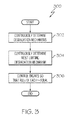
- this method 300 is depicted in flowchart form in FIG. 3 , and will now be described. In doing so, it should be noted that the parenthetic reference numerals in the following description refer to like-numbered flowchart symbols in FIG. 3 .
- the depicted method 300 includes the steps of continuously, and in real-time, determining a plurality of different degradation mechanisms for each of the plurality of engines (302). As already described above, these degradation mechanisms are determined based on the engine performance margin, modeled failure predictions of the hot gas components, and modeled failure predictions of the non-hot gas components. Thereafter, a determination is made, continuously and in real-time, as to which of the determined degradation mechanisms is most limiting (304). The plurality of engines 102 are then controlled, based on the most limiting degradation mechanism, in a manner that the remaining useful lives of each engine are substantially equal (306).
- the system and method described herein provide real-time engine condition assessment and management to assist aircraft pilots in readily managing deteriorating engine conditions.
- Skilled artisans may implement the described functionality in varying ways for each particular application, but such implementation decisions should not be interpreted as causing a departure from the scope of the present invention.
- an embodiment of a system or a component may employ various integrated circuit components, e.g., memory elements, digital signal processing elements, logic elements, look-up tables, or the like, which may carry out a variety of functions under the control of one or more microprocessors or other control devices.
- integrated circuit components e.g., memory elements, digital signal processing elements, logic elements, look-up tables, or the like, which may carry out a variety of functions under the control of one or more microprocessors or other control devices.
- DSP digital signal processor
- ASIC application specific integrated circuit
- FPGA field programmable gate array
- a general-purpose processor may be a microprocessor, but in the alternative, the processor may be any conventional processor, controller, microcontroller, or state machine.
- a processor may also be implemented as a combination of computing devices, e.g., a combination of a DSP and a microprocessor, a plurality of microprocessors, one or more microprocessors in conjunction with a DSP core, or any other such configuration.
- a software module may reside in RAM memory, flash memory, ROM memory, EPROM memory, EEPROM memory, registers, hard disk, a removable disk, a CD-ROM, or any other form of storage medium known in the art.
- An exemplary storage medium is coupled to the processor such that the processor can read information from, and write information to, the storage medium.
- the storage medium may be integral to the processor.
- the processor and the storage medium may reside in an ASIC.
- the ASIC may reside in a user terminal.
- the processor and the storage medium may reside as discrete components in a user terminal.
Landscapes
- Engineering & Computer Science (AREA)
- Chemical & Material Sciences (AREA)
- Combustion & Propulsion (AREA)
- Mechanical Engineering (AREA)
- General Engineering & Computer Science (AREA)
- Physics & Mathematics (AREA)
- General Physics & Mathematics (AREA)
- Automation & Control Theory (AREA)
- Quality & Reliability (AREA)
- Aviation & Aerospace Engineering (AREA)
- Combined Controls Of Internal Combustion Engines (AREA)
- Testing Of Engines (AREA)
- Control Of Turbines (AREA)
Applications Claiming Priority (1)
| Application Number | Priority Date | Filing Date | Title |
|---|---|---|---|
| US14/030,039 US9221535B2 (en) | 2013-09-18 | 2013-09-18 | Adaptive remaining useful life balancing control system and method for multi-engine systems |
Publications (2)
| Publication Number | Publication Date |
|---|---|
| EP2851759A1 true EP2851759A1 (de) | 2015-03-25 |
| EP2851759B1 EP2851759B1 (de) | 2018-07-25 |
Family
ID=51417204
Family Applications (1)
| Application Number | Title | Priority Date | Filing Date |
|---|---|---|---|
| EP14182715.4A Not-in-force EP2851759B1 (de) | 2013-09-18 | 2014-08-28 | Verfahren und System zur adaptiven Ausgleichssteuerung der verbleibenden Lebensdauer eines Motors in einem mehrmotorigen System |
Country Status (3)
| Country | Link |
|---|---|
| US (1) | US9221535B2 (de) |
| EP (1) | EP2851759B1 (de) |
| CA (1) | CA2861362C (de) |
Cited By (5)
| Publication number | Priority date | Publication date | Assignee | Title |
|---|---|---|---|---|
| CN106884725A (zh) * | 2015-12-16 | 2017-06-23 | 通用电气公司 | 在燃气涡轮调节中对功率输出‑排放参数的概率控制 |
| EP3243754A1 (de) * | 2016-05-09 | 2017-11-15 | Rolls-Royce Corporation | Mehrfachmotorzustandsanpassung mittels elektrischer leistungssteuerung |
| WO2018178566A1 (fr) * | 2017-03-28 | 2018-10-04 | Arianegroup Sas | Procédé de pilotage d'une baie multimoteurs, système de commande pour baie multimoteurs et baie multimoteurs |
| EP3385806A1 (de) * | 2017-04-03 | 2018-10-10 | General Electric Company | Steuerungssysteme und verfahren zur steuerung von leistungssystemen basierend auf betriebszuverlässigkeit und betriebsanomalien |
| US10442544B2 (en) | 2016-05-09 | 2019-10-15 | Rolls-Royce North American Technologies, Inc. | Engine degradation management via multi-engine mechanical power control |
Families Citing this family (12)
| Publication number | Priority date | Publication date | Assignee | Title |
|---|---|---|---|---|
| US9944400B2 (en) * | 2014-02-11 | 2018-04-17 | Sikorsky Aircraft Corporation | Adaptive engine acceleration for accessory loads |
| US9785919B2 (en) | 2015-12-10 | 2017-10-10 | General Electric Company | Automatic classification of aircraft component distress |
| FR3064248A1 (fr) * | 2017-03-27 | 2018-09-28 | Airbus Operations (S.A.S.) | Procede de coupure automatique des moteurs d'un aeronef bimoteur |
| US10633104B2 (en) | 2017-05-17 | 2020-04-28 | General Electric Company | Hybrid-electric propulsion system for an aircraft |
| US11293353B2 (en) | 2017-05-31 | 2022-04-05 | Raytheon Technologies Corporation | Transient control to extend part life in gas turbine engine |
| US10800536B2 (en) | 2017-06-09 | 2020-10-13 | General Electric Company | Propulsion system for an aircraft |
| US10006375B1 (en) | 2017-07-11 | 2018-06-26 | General Electric Company | Propulsion system for an aircraft |
| CN110821677A (zh) | 2018-08-08 | 2020-02-21 | 普拉特 - 惠特尼加拿大公司 | 多发动机系统和方法 |
| US12241426B2 (en) * | 2019-01-03 | 2025-03-04 | General Electric Company | Systems and methods of controlling load share and speed of engines in multiple-engine propulsion systems |
| US11427353B2 (en) | 2019-12-13 | 2022-08-30 | Pratt & Whitney Canada Corp. | System and method for testing engine performance in-flight |
| US12554980B2 (en) | 2021-03-03 | 2026-02-17 | International Business Machines Corporation | Estimating remaining useful life based on operation and degradation characteristics |
| US12480449B2 (en) | 2022-08-22 | 2025-11-25 | General Electric Company | Propulsion system including an electric machine for starting a gas turbine engine |
Citations (4)
| Publication number | Priority date | Publication date | Assignee | Title |
|---|---|---|---|---|
| EP0199038A1 (de) * | 1985-04-19 | 1986-10-29 | Allied Corporation | Kontrolleinrichtung zum Kontrollieren eines Motors von einem Kraftturbinensystem mit mehr als einem Motor |
| EP1420153A2 (de) * | 2002-11-13 | 2004-05-19 | General Electric Company | Adaptive Regelung für Gasturbinen |
| EP2221699A2 (de) * | 2009-02-06 | 2010-08-25 | Honeywell International Inc. | Durchgehendes Leistungsanalysesystem und Verfahren |
| US20120283963A1 (en) * | 2011-05-05 | 2012-11-08 | Mitchell David J | Method for predicting a remaining useful life of an engine and components thereof |
Family Cites Families (16)
| Publication number | Priority date | Publication date | Assignee | Title |
|---|---|---|---|---|
| US4488851A (en) | 1982-04-01 | 1984-12-18 | The United States Of America As Represented By The Secretary Of The Army | Power management system |
| US4500966A (en) | 1982-05-26 | 1985-02-19 | Chandler Evans Inc. | Super contingency aircraft engine control |
| US5633800A (en) * | 1992-10-21 | 1997-05-27 | General Electric Company | Integrated model-based reasoning/expert system diagnosis for rotating machinery |
| US20010045835A1 (en) * | 2000-02-25 | 2001-11-29 | Ahmed Adel Abdel Aziz | Method and apparatus for detecting timing belt damage by inductive coupling |
| US6860100B1 (en) * | 2000-03-17 | 2005-03-01 | Ford Global Technologies, Llc | Degradation detection method for an engine having a NOx sensor |
| US6707475B1 (en) | 2000-09-19 | 2004-03-16 | Honeywell International Inc. | System for selecting and displaying flight management system procedures |
| US6917908B2 (en) | 2001-03-16 | 2005-07-12 | Bell Helicopter Textron Inc. | Method of pilot training using simulated engine failure |
| DE60235317D1 (de) * | 2001-11-13 | 2010-03-25 | Goodrich Pump & Engine Control | Fehlerverwaltungssystem für gasturbinentriebwerke |
| US20040049715A1 (en) * | 2002-09-05 | 2004-03-11 | Jaw Link C. | Computer networked intelligent condition-based engine/equipment management system |
| CA2634470C (en) * | 2003-01-24 | 2013-05-14 | Pratt & Whitney Canada Corp. | Method and system for trend detection and analysis |
| US8025503B2 (en) * | 2003-12-08 | 2011-09-27 | Pratt & Whitney Canada Corp. | One-engine-inoperative training method and system |
| US7702435B2 (en) * | 2004-11-05 | 2010-04-20 | Honeywell International Inc. | Method and apparatus for system monitoring and maintenance |
| CA2487704A1 (en) | 2004-11-18 | 2006-05-18 | R. Kyle Schmidt | Method and system for health monitoring of aircraft landing gear |
| US7414544B2 (en) | 2005-01-28 | 2008-08-19 | Bell Helicopter Textron, Inc. | Power situation indicator |
| FR2900385B1 (fr) * | 2006-04-28 | 2008-12-26 | Eurocopter France | Procede et dispositif d'aide au pilotage d'un giravion au decollage. |
| FR2952907B1 (fr) | 2009-11-26 | 2011-12-09 | Eurocopter France | Installation motrice, helicoptere comportant une telle installation motrice, et procede mis en oeuvre par cette installation motrice |
-
2013
- 2013-09-18 US US14/030,039 patent/US9221535B2/en not_active Expired - Fee Related
-
2014
- 2014-08-28 EP EP14182715.4A patent/EP2851759B1/de not_active Not-in-force
- 2014-08-29 CA CA2861362A patent/CA2861362C/en active Active
Patent Citations (5)
| Publication number | Priority date | Publication date | Assignee | Title |
|---|---|---|---|---|
| EP0199038A1 (de) * | 1985-04-19 | 1986-10-29 | Allied Corporation | Kontrolleinrichtung zum Kontrollieren eines Motors von einem Kraftturbinensystem mit mehr als einem Motor |
| EP1420153A2 (de) * | 2002-11-13 | 2004-05-19 | General Electric Company | Adaptive Regelung für Gasturbinen |
| EP2221699A2 (de) * | 2009-02-06 | 2010-08-25 | Honeywell International Inc. | Durchgehendes Leistungsanalysesystem und Verfahren |
| US8068997B2 (en) | 2009-02-06 | 2011-11-29 | Honeywell International Inc. | Continuous performance analysis system and method |
| US20120283963A1 (en) * | 2011-05-05 | 2012-11-08 | Mitchell David J | Method for predicting a remaining useful life of an engine and components thereof |
Cited By (8)
| Publication number | Priority date | Publication date | Assignee | Title |
|---|---|---|---|---|
| CN106884725A (zh) * | 2015-12-16 | 2017-06-23 | 通用电气公司 | 在燃气涡轮调节中对功率输出‑排放参数的概率控制 |
| CN106884725B (zh) * | 2015-12-16 | 2020-12-25 | 通用电气公司 | 在燃气涡轮调节中对功率输出-排放参数的概率控制 |
| EP3243754A1 (de) * | 2016-05-09 | 2017-11-15 | Rolls-Royce Corporation | Mehrfachmotorzustandsanpassung mittels elektrischer leistungssteuerung |
| US10038397B2 (en) | 2016-05-09 | 2018-07-31 | Rolls-Royce Corporation | Multiple engine condition matching via electrical power extraction control |
| US10442544B2 (en) | 2016-05-09 | 2019-10-15 | Rolls-Royce North American Technologies, Inc. | Engine degradation management via multi-engine mechanical power control |
| WO2018178566A1 (fr) * | 2017-03-28 | 2018-10-04 | Arianegroup Sas | Procédé de pilotage d'une baie multimoteurs, système de commande pour baie multimoteurs et baie multimoteurs |
| FR3064604A1 (fr) * | 2017-03-28 | 2018-10-05 | Airbus Safran Launchers Sas | Procede de pilotage d'une baie multimoteurs, systeme de commande pour baie multimoteurs et baie multimoteurs |
| EP3385806A1 (de) * | 2017-04-03 | 2018-10-10 | General Electric Company | Steuerungssysteme und verfahren zur steuerung von leistungssystemen basierend auf betriebszuverlässigkeit und betriebsanomalien |
Also Published As
| Publication number | Publication date |
|---|---|
| US9221535B2 (en) | 2015-12-29 |
| CA2861362C (en) | 2021-08-24 |
| US20150081193A1 (en) | 2015-03-19 |
| EP2851759B1 (de) | 2018-07-25 |
| CA2861362A1 (en) | 2015-03-18 |
Similar Documents
| Publication | Publication Date | Title |
|---|---|---|
| CA2861362C (en) | Adaptive remaining useful life balancing control system and method for multi-engine systems | |
| CN105986907B (zh) | 燃气涡轮发动机健康确定 | |
| EP2597258B1 (de) | Vorrichtung und methode zur überwachung einer gasturbine | |
| EP2740916B1 (de) | Betriebsstützsysteme und verfahren zum berechnen und bewerten von turbinentemperaturen und -gesundheit | |
| US10822996B2 (en) | Gas turbine engine health determination | |
| US9547990B2 (en) | Rotary-wing aircraft emergency landing control | |
| CA2377157C (en) | Method of pilot training using simulated engine failure | |
| EP2972611A1 (de) | Modellbasierte verteilte zustandsüberwachung für flugzeugmotoren | |
| US11667392B2 (en) | Method and system for operating a rotorcraft engine | |
| US6904340B2 (en) | Flight control indicator for an aircraft, in particular a transport airplane, intended to supply the thrust generated by at least one engine of the aircraft | |
| EP3356231A1 (de) | Verfahren und system zur darstellung eines betriebszustands eines flugzeugmotors | |
| CA3132290A1 (en) | Indicators for hybrid electrical powerplants | |
| EP2993311A1 (de) | System und verfahren zur reduzierung von triebwerksinduzierter flugzeugkabinenresonanz | |
| CA3060153C (en) | Aircraft maintenance systems and methods | |
| US10082184B2 (en) | System and method for eliminating adverse clutch vibratory responses | |
| EP3106649B1 (de) | Steuerung einer flugzeuggasturbine ohne totaltemperatursensoren des flugzeugs | |
| US20240300662A1 (en) | Power management system and controls for hybrid electric aircraft | |
| JP2009509088A (ja) | 多発航空機をこれらエンジンに関するデータにより操縦する方法と装置 | |
| US12437668B2 (en) | Rotorcraft flight training method, associated system and rotorcraft | |
| US20250187741A1 (en) | Method for assisting the piloting of a rotorcraft and rotorcraft thus equipped | |
| Spless et al. | Effects on helicopter dynamics in case of engine failure during intended single engine operation | |
| Lenox | Digital Control Makes a Commercial Debut on the JT9D Engine |
Legal Events
| Date | Code | Title | Description |
|---|---|---|---|
| PUAI | Public reference made under article 153(3) epc to a published international application that has entered the european phase |
Free format text: ORIGINAL CODE: 0009012 |
|
| 17P | Request for examination filed |
Effective date: 20140828 |
|
| AK | Designated contracting states |
Kind code of ref document: A1 Designated state(s): AL AT BE BG CH CY CZ DE DK EE ES FI FR GB GR HR HU IE IS IT LI LT LU LV MC MK MT NL NO PL PT RO RS SE SI SK SM TR |
|
| AX | Request for extension of the european patent |
Extension state: BA ME |
|
| RAP1 | Party data changed (applicant data changed or rights of an application transferred) |
Owner name: HONEYWELL INTERNATIONAL INC. |
|
| GRAP | Despatch of communication of intention to grant a patent |
Free format text: ORIGINAL CODE: EPIDOSNIGR1 |
|
| INTG | Intention to grant announced |
Effective date: 20180316 |
|
| RIN1 | Information on inventor provided before grant (corrected) |
Inventor name: PERALTA-DURAN, HECTOR ALONSO Inventor name: LING, RICHARD Inventor name: GORDON, GRANT Inventor name: GORELIK, MICHAEL |
|
| GRAS | Grant fee paid |
Free format text: ORIGINAL CODE: EPIDOSNIGR3 |
|
| GRAA | (expected) grant |
Free format text: ORIGINAL CODE: 0009210 |
|
| AK | Designated contracting states |
Kind code of ref document: B1 Designated state(s): AL AT BE BG CH CY CZ DE DK EE ES FI FR GB GR HR HU IE IS IT LI LT LU LV MC MK MT NL NO PL PT RO RS SE SI SK SM TR |
|
| REG | Reference to a national code |
Ref country code: GB Ref legal event code: FG4D |
|
| REG | Reference to a national code |
Ref country code: CH Ref legal event code: EP |
|
| REG | Reference to a national code |
Ref country code: AT Ref legal event code: REF Ref document number: 1022417 Country of ref document: AT Kind code of ref document: T Effective date: 20180815 |
|
| REG | Reference to a national code |
Ref country code: IE Ref legal event code: FG4D |
|
| REG | Reference to a national code |
Ref country code: DE Ref legal event code: R096 Ref document number: 602014029005 Country of ref document: DE |
|
| REG | Reference to a national code |
Ref country code: FR Ref legal event code: PLFP Year of fee payment: 5 |
|
| REG | Reference to a national code |
Ref country code: NL Ref legal event code: MP Effective date: 20180725 |
|
| REG | Reference to a national code |
Ref country code: LT Ref legal event code: MG4D |
|
| PG25 | Lapsed in a contracting state [announced via postgrant information from national office to epo] |
Ref country code: NL Free format text: LAPSE BECAUSE OF FAILURE TO SUBMIT A TRANSLATION OF THE DESCRIPTION OR TO PAY THE FEE WITHIN THE PRESCRIBED TIME-LIMIT Effective date: 20180725 |
|
| REG | Reference to a national code |
Ref country code: AT Ref legal event code: MK05 Ref document number: 1022417 Country of ref document: AT Kind code of ref document: T Effective date: 20180725 |
|
| PG25 | Lapsed in a contracting state [announced via postgrant information from national office to epo] |
Ref country code: BG Free format text: LAPSE BECAUSE OF FAILURE TO SUBMIT A TRANSLATION OF THE DESCRIPTION OR TO PAY THE FEE WITHIN THE PRESCRIBED TIME-LIMIT Effective date: 20181025 Ref country code: SE Free format text: LAPSE BECAUSE OF FAILURE TO SUBMIT A TRANSLATION OF THE DESCRIPTION OR TO PAY THE FEE WITHIN THE PRESCRIBED TIME-LIMIT Effective date: 20180725 Ref country code: AT Free format text: LAPSE BECAUSE OF FAILURE TO SUBMIT A TRANSLATION OF THE DESCRIPTION OR TO PAY THE FEE WITHIN THE PRESCRIBED TIME-LIMIT Effective date: 20180725 Ref country code: NO Free format text: LAPSE BECAUSE OF FAILURE TO SUBMIT A TRANSLATION OF THE DESCRIPTION OR TO PAY THE FEE WITHIN THE PRESCRIBED TIME-LIMIT Effective date: 20181025 Ref country code: GR Free format text: LAPSE BECAUSE OF FAILURE TO SUBMIT A TRANSLATION OF THE DESCRIPTION OR TO PAY THE FEE WITHIN THE PRESCRIBED TIME-LIMIT Effective date: 20181026 Ref country code: LT Free format text: LAPSE BECAUSE OF FAILURE TO SUBMIT A TRANSLATION OF THE DESCRIPTION OR TO PAY THE FEE WITHIN THE PRESCRIBED TIME-LIMIT Effective date: 20180725 Ref country code: RS Free format text: LAPSE BECAUSE OF FAILURE TO SUBMIT A TRANSLATION OF THE DESCRIPTION OR TO PAY THE FEE WITHIN THE PRESCRIBED TIME-LIMIT Effective date: 20180725 Ref country code: PL Free format text: LAPSE BECAUSE OF FAILURE TO SUBMIT A TRANSLATION OF THE DESCRIPTION OR TO PAY THE FEE WITHIN THE PRESCRIBED TIME-LIMIT Effective date: 20180725 Ref country code: FI Free format text: LAPSE BECAUSE OF FAILURE TO SUBMIT A TRANSLATION OF THE DESCRIPTION OR TO PAY THE FEE WITHIN THE PRESCRIBED TIME-LIMIT Effective date: 20180725 Ref country code: IS Free format text: LAPSE BECAUSE OF FAILURE TO SUBMIT A TRANSLATION OF THE DESCRIPTION OR TO PAY THE FEE WITHIN THE PRESCRIBED TIME-LIMIT Effective date: 20181125 |
|
| PG25 | Lapsed in a contracting state [announced via postgrant information from national office to epo] |
Ref country code: AL Free format text: LAPSE BECAUSE OF FAILURE TO SUBMIT A TRANSLATION OF THE DESCRIPTION OR TO PAY THE FEE WITHIN THE PRESCRIBED TIME-LIMIT Effective date: 20180725 Ref country code: LV Free format text: LAPSE BECAUSE OF FAILURE TO SUBMIT A TRANSLATION OF THE DESCRIPTION OR TO PAY THE FEE WITHIN THE PRESCRIBED TIME-LIMIT Effective date: 20180725 Ref country code: HR Free format text: LAPSE BECAUSE OF FAILURE TO SUBMIT A TRANSLATION OF THE DESCRIPTION OR TO PAY THE FEE WITHIN THE PRESCRIBED TIME-LIMIT Effective date: 20180725 |
|
| REG | Reference to a national code |
Ref country code: CH Ref legal event code: PL |
|
| REG | Reference to a national code |
Ref country code: DE Ref legal event code: R097 Ref document number: 602014029005 Country of ref document: DE |
|
| PG25 | Lapsed in a contracting state [announced via postgrant information from national office to epo] |
Ref country code: IT Free format text: LAPSE BECAUSE OF FAILURE TO SUBMIT A TRANSLATION OF THE DESCRIPTION OR TO PAY THE FEE WITHIN THE PRESCRIBED TIME-LIMIT Effective date: 20180725 Ref country code: CZ Free format text: LAPSE BECAUSE OF FAILURE TO SUBMIT A TRANSLATION OF THE DESCRIPTION OR TO PAY THE FEE WITHIN THE PRESCRIBED TIME-LIMIT Effective date: 20180725 Ref country code: LI Free format text: LAPSE BECAUSE OF NON-PAYMENT OF DUE FEES Effective date: 20180831 Ref country code: EE Free format text: LAPSE BECAUSE OF FAILURE TO SUBMIT A TRANSLATION OF THE DESCRIPTION OR TO PAY THE FEE WITHIN THE PRESCRIBED TIME-LIMIT Effective date: 20180725 Ref country code: RO Free format text: LAPSE BECAUSE OF FAILURE TO SUBMIT A TRANSLATION OF THE DESCRIPTION OR TO PAY THE FEE WITHIN THE PRESCRIBED TIME-LIMIT Effective date: 20180725 Ref country code: LU Free format text: LAPSE BECAUSE OF NON-PAYMENT OF DUE FEES Effective date: 20180828 Ref country code: MC Free format text: LAPSE BECAUSE OF FAILURE TO SUBMIT A TRANSLATION OF THE DESCRIPTION OR TO PAY THE FEE WITHIN THE PRESCRIBED TIME-LIMIT Effective date: 20180725 Ref country code: ES Free format text: LAPSE BECAUSE OF FAILURE TO SUBMIT A TRANSLATION OF THE DESCRIPTION OR TO PAY THE FEE WITHIN THE PRESCRIBED TIME-LIMIT Effective date: 20180725 Ref country code: CH Free format text: LAPSE BECAUSE OF NON-PAYMENT OF DUE FEES Effective date: 20180831 |
|
| REG | Reference to a national code |
Ref country code: BE Ref legal event code: MM Effective date: 20180831 |
|
| PG25 | Lapsed in a contracting state [announced via postgrant information from national office to epo] |
Ref country code: SK Free format text: LAPSE BECAUSE OF FAILURE TO SUBMIT A TRANSLATION OF THE DESCRIPTION OR TO PAY THE FEE WITHIN THE PRESCRIBED TIME-LIMIT Effective date: 20180725 Ref country code: DK Free format text: LAPSE BECAUSE OF FAILURE TO SUBMIT A TRANSLATION OF THE DESCRIPTION OR TO PAY THE FEE WITHIN THE PRESCRIBED TIME-LIMIT Effective date: 20180725 Ref country code: SM Free format text: LAPSE BECAUSE OF FAILURE TO SUBMIT A TRANSLATION OF THE DESCRIPTION OR TO PAY THE FEE WITHIN THE PRESCRIBED TIME-LIMIT Effective date: 20180725 |
|
| PLBE | No opposition filed within time limit |
Free format text: ORIGINAL CODE: 0009261 |
|
| STAA | Information on the status of an ep patent application or granted ep patent |
Free format text: STATUS: NO OPPOSITION FILED WITHIN TIME LIMIT |
|
| 26N | No opposition filed |
Effective date: 20190426 |
|
| PG25 | Lapsed in a contracting state [announced via postgrant information from national office to epo] |
Ref country code: SI Free format text: LAPSE BECAUSE OF FAILURE TO SUBMIT A TRANSLATION OF THE DESCRIPTION OR TO PAY THE FEE WITHIN THE PRESCRIBED TIME-LIMIT Effective date: 20180725 Ref country code: BE Free format text: LAPSE BECAUSE OF NON-PAYMENT OF DUE FEES Effective date: 20180831 |
|
| PG25 | Lapsed in a contracting state [announced via postgrant information from national office to epo] |
Ref country code: MT Free format text: LAPSE BECAUSE OF NON-PAYMENT OF DUE FEES Effective date: 20180828 |
|
| PG25 | Lapsed in a contracting state [announced via postgrant information from national office to epo] |
Ref country code: TR Free format text: LAPSE BECAUSE OF FAILURE TO SUBMIT A TRANSLATION OF THE DESCRIPTION OR TO PAY THE FEE WITHIN THE PRESCRIBED TIME-LIMIT Effective date: 20180725 |
|
| PG25 | Lapsed in a contracting state [announced via postgrant information from national office to epo] |
Ref country code: HU Free format text: LAPSE BECAUSE OF FAILURE TO SUBMIT A TRANSLATION OF THE DESCRIPTION OR TO PAY THE FEE WITHIN THE PRESCRIBED TIME-LIMIT; INVALID AB INITIO Effective date: 20140828 Ref country code: PT Free format text: LAPSE BECAUSE OF FAILURE TO SUBMIT A TRANSLATION OF THE DESCRIPTION OR TO PAY THE FEE WITHIN THE PRESCRIBED TIME-LIMIT Effective date: 20180725 |
|
| PG25 | Lapsed in a contracting state [announced via postgrant information from national office to epo] |
Ref country code: MK Free format text: LAPSE BECAUSE OF NON-PAYMENT OF DUE FEES Effective date: 20180725 Ref country code: IE Free format text: LAPSE BECAUSE OF NON-PAYMENT OF DUE FEES Effective date: 20180828 Ref country code: CY Free format text: LAPSE BECAUSE OF FAILURE TO SUBMIT A TRANSLATION OF THE DESCRIPTION OR TO PAY THE FEE WITHIN THE PRESCRIBED TIME-LIMIT Effective date: 20180725 |
|
| PGFP | Annual fee paid to national office [announced via postgrant information from national office to epo] |
Ref country code: GB Payment date: 20220823 Year of fee payment: 9 Ref country code: DE Payment date: 20220826 Year of fee payment: 9 |
|
| PGFP | Annual fee paid to national office [announced via postgrant information from national office to epo] |
Ref country code: FR Payment date: 20220824 Year of fee payment: 9 |
|
| P01 | Opt-out of the competence of the unified patent court (upc) registered |
Effective date: 20230525 |
|
| REG | Reference to a national code |
Ref country code: DE Ref legal event code: R119 Ref document number: 602014029005 Country of ref document: DE |
|
| GBPC | Gb: european patent ceased through non-payment of renewal fee |
Effective date: 20230828 |
|
| PG25 | Lapsed in a contracting state [announced via postgrant information from national office to epo] |
Ref country code: GB Free format text: LAPSE BECAUSE OF NON-PAYMENT OF DUE FEES Effective date: 20230828 |
|
| PG25 | Lapsed in a contracting state [announced via postgrant information from national office to epo] |
Ref country code: GB Free format text: LAPSE BECAUSE OF NON-PAYMENT OF DUE FEES Effective date: 20230828 Ref country code: FR Free format text: LAPSE BECAUSE OF NON-PAYMENT OF DUE FEES Effective date: 20230831 Ref country code: DE Free format text: LAPSE BECAUSE OF NON-PAYMENT OF DUE FEES Effective date: 20240301 |