EP2851785A2 - System und Verfahren mit zwei Bildschirmen - Google Patents
System und Verfahren mit zwei Bildschirmen Download PDFInfo
- Publication number
- EP2851785A2 EP2851785A2 EP14183046.3A EP14183046A EP2851785A2 EP 2851785 A2 EP2851785 A2 EP 2851785A2 EP 14183046 A EP14183046 A EP 14183046A EP 2851785 A2 EP2851785 A2 EP 2851785A2
- Authority
- EP
- European Patent Office
- Prior art keywords
- computing device
- screen
- terminal
- touch screen
- application program
- Prior art date
- Legal status (The legal status is an assumption and is not a legal conclusion. Google has not performed a legal analysis and makes no representation as to the accuracy of the status listed.)
- Granted
Links
Images






Classifications
-
- G—PHYSICS
- G06—COMPUTING OR CALCULATING; COUNTING
- G06F—ELECTRIC DIGITAL DATA PROCESSING
- G06F3/00—Input arrangements for transferring data to be processed into a form capable of being handled by the computer; Output arrangements for transferring data from processing unit to output unit, e.g. interface arrangements
- G06F3/14—Digital output to display device ; Cooperation and interconnection of the display device with other functional units
- G06F3/1423—Digital output to display device ; Cooperation and interconnection of the display device with other functional units controlling a plurality of local displays, e.g. CRT and flat panel display
- G06F3/1438—Digital output to display device ; Cooperation and interconnection of the display device with other functional units controlling a plurality of local displays, e.g. CRT and flat panel display using more than one graphics controller
-
- G—PHYSICS
- G06—COMPUTING OR CALCULATING; COUNTING
- G06F—ELECTRIC DIGITAL DATA PROCESSING
- G06F13/00—Interconnection of, or transfer of information or other signals between, memories, input/output devices or central processing units
- G06F13/14—Handling requests for interconnection or transfer
-
- G—PHYSICS
- G06—COMPUTING OR CALCULATING; COUNTING
- G06F—ELECTRIC DIGITAL DATA PROCESSING
- G06F3/00—Input arrangements for transferring data to be processed into a form capable of being handled by the computer; Output arrangements for transferring data from processing unit to output unit, e.g. interface arrangements
- G06F3/01—Input arrangements or combined input and output arrangements for interaction between user and computer
- G06F3/048—Interaction techniques based on graphical user interfaces [GUI]
- G06F3/0481—Interaction techniques based on graphical user interfaces [GUI] based on specific properties of the displayed interaction object or a metaphor-based environment, e.g. interaction with desktop elements like windows or icons, or assisted by a cursor's changing behaviour or appearance
-
- G—PHYSICS
- G06—COMPUTING OR CALCULATING; COUNTING
- G06F—ELECTRIC DIGITAL DATA PROCESSING
- G06F1/00—Details not covered by groups G06F3/00 - G06F13/00 and G06F21/00
- G06F1/16—Constructional details or arrangements
-
- G—PHYSICS
- G06—COMPUTING OR CALCULATING; COUNTING
- G06F—ELECTRIC DIGITAL DATA PROCESSING
- G06F1/00—Details not covered by groups G06F3/00 - G06F13/00 and G06F21/00
- G06F1/16—Constructional details or arrangements
- G06F1/1601—Constructional details related to the housing of computer displays, e.g. of CRT monitors, of flat displays
-
- G—PHYSICS
- G06—COMPUTING OR CALCULATING; COUNTING
- G06F—ELECTRIC DIGITAL DATA PROCESSING
- G06F1/00—Details not covered by groups G06F3/00 - G06F13/00 and G06F21/00
- G06F1/16—Constructional details or arrangements
- G06F1/1613—Constructional details or arrangements for portable computers
- G06F1/1633—Constructional details or arrangements of portable computers not specific to the type of enclosures covered by groups G06F1/1615 - G06F1/1626
- G06F1/1637—Details related to the display arrangement, including those related to the mounting of the display in the housing
- G06F1/1643—Details related to the display arrangement, including those related to the mounting of the display in the housing the display being associated to a digitizer, e.g. laptops that can be used as penpads
-
- G—PHYSICS
- G06—COMPUTING OR CALCULATING; COUNTING
- G06F—ELECTRIC DIGITAL DATA PROCESSING
- G06F3/00—Input arrangements for transferring data to be processed into a form capable of being handled by the computer; Output arrangements for transferring data from processing unit to output unit, e.g. interface arrangements
- G06F3/01—Input arrangements or combined input and output arrangements for interaction between user and computer
- G06F3/048—Interaction techniques based on graphical user interfaces [GUI]
- G06F3/0487—Interaction techniques based on graphical user interfaces [GUI] using specific features provided by the input device, e.g. functions controlled by the rotation of a mouse with dual sensing arrangements, or of the nature of the input device, e.g. tap gestures based on pressure sensed by a digitiser
- G06F3/0488—Interaction techniques based on graphical user interfaces [GUI] using specific features provided by the input device, e.g. functions controlled by the rotation of a mouse with dual sensing arrangements, or of the nature of the input device, e.g. tap gestures based on pressure sensed by a digitiser using a touch-screen or digitiser, e.g. input of commands through traced gestures
-
- G—PHYSICS
- G06—COMPUTING OR CALCULATING; COUNTING
- G06F—ELECTRIC DIGITAL DATA PROCESSING
- G06F3/00—Input arrangements for transferring data to be processed into a form capable of being handled by the computer; Output arrangements for transferring data from processing unit to output unit, e.g. interface arrangements
- G06F3/14—Digital output to display device ; Cooperation and interconnection of the display device with other functional units
-
- G—PHYSICS
- G06—COMPUTING OR CALCULATING; COUNTING
- G06F—ELECTRIC DIGITAL DATA PROCESSING
- G06F3/00—Input arrangements for transferring data to be processed into a form capable of being handled by the computer; Output arrangements for transferring data from processing unit to output unit, e.g. interface arrangements
- G06F3/14—Digital output to display device ; Cooperation and interconnection of the display device with other functional units
- G06F3/1407—General aspects irrespective of display type, e.g. determination of decimal point position, display with fixed or driving decimal point, suppression of non-significant zeros
-
- G—PHYSICS
- G09—EDUCATION; CRYPTOGRAPHY; DISPLAY; ADVERTISING; SEALS
- G09G—ARRANGEMENTS OR CIRCUITS FOR CONTROL OF INDICATING DEVICES USING STATIC MEANS TO PRESENT VARIABLE INFORMATION
- G09G5/00—Control arrangements or circuits for visual indicators common to cathode-ray tube indicators and other visual indicators
- G09G5/14—Display of multiple viewports
Definitions
- the present disclosure relates generally to a dual monitor system and method, and more particularly to a dual monitor system and method using a terminal including a touch screen and a computing device including a screen.
- Electronic devices including recently developed computers can provide users with various functions by executing application programs through processors.
- the electronic device can simultaneously perform several tasks and connect a main body of the electronic device to two or more screens to meet a multitasking environment, so as to support a dual monitoring mode in which respective task environments are displayed.
- various terminals are used as electronic devices which can be carried by users today. According to the development of technologies, the electronic devices in a comprehensive multimedia device type having complex functions such as not only a voice call but also a video call, taking a picture or a video, reproducing music and a video file, receiving a broadcast, playing a game and wireless Internet and the like are released. Specifications of a processor installed in the terminal are being improved at an alarming rate and terminals which provide light and large screens within a portable range are being developed. Further, a terminal including a touch screen is currently provided to increase the interface convenience of the user.
- a portable terminal and a computing device provided to process various tasks in a fixed location may provide the user with different functions as necessary. Accordingly, the user may require simultaneously use of the terminal and the computing device, but it is inconvenient for the user to separately control the terminal and the computing device.
- a method for dual screen presentation, using a touch screen of a terminal and a screen of a computing device includes recognizing a connection between the mobile terminal and the computing device, detecting an application program window moving into a scope of a screen of the mobile terminal from a scope of a screen of the computing device, and displaying the application program window on a touch screen of the mobile terminal.
- the method further includes detecting a pointer moving from the scope of the screen of the mobile terminal onto the scope of the screen of the computing device; and transmitting the pointer to the computing device, where the screen of the computing device displays the pointer.
- the method further includes moving a user interface of the mobile terminal onto the screen of the computing device.
- a function of the mobile terminal is provided through the user interface of the terminal which is copied to the screen of the computing device.
- the terminal is attached to one side of the screen of the computing device.
- moving the predetermined application program window comprises, when the predetermined application program window is moved in a preset direction by a predetermined distance or more, moving the predetermined application program window to the touch screen of the terminal from the screen of the computing device.
- the method further includes moving the user interface of the terminal which is copied to the screen of the computing device to the touch screen of the terminal in response to the user input.
- the moving of the user interface comprises, when an application program window executed by the computing device exists on the touch screen of the terminal, blocking movement of the copied user interface to the touch screen of the terminal.
- an application program window which is executed on the touch screen of the terminal by the computing device, is generated on the screen of the computing device.
- a mobile terminal includes a transceiver configured to communicate data with a computing device, a touch screen configured to display an image or a video, and a controller configured to detect an application program window moving into a scope of a screen of the mobile terminal from a scope of a screen of the computing device, and cause the touch screen to display the application program window.
- a computing device for dual screen presentation includes a transceiver configured to communicate data with a mobile terminal, a screen configured to display an image or a video, and a controller configured to receive a user interface of the mobile terminal from the mobile screen, and cause the screen to display the user interface.
- FIGURES 1A through 7 discussed below, and the various embodiments used to describe the principles of the present disclosure in this patent document are by way of illustration only and should not be construed in any way to limit the scope of the disclosure. Those skilled in the art will understand that the principles of the present disclosure may be implemented in any suitably arranged electronic devices.
- exemplary embodiments of the present disclosure will be described with reference to the accompanying drawings. It is noted that, where possible, the same reference numerals are designated to the same components in the accompanying drawings. Further, a detailed description of a known function and configuration which may make the subject matter of the present disclosure unclear will be omitted.
- a computing device described in the specification and drawings may include all electronic devices which provide a user with various functions by executing application programs through a process stored in a memory.
- a “dual monitor mode” used in the specification and drawings refers to a case where a task environment of an application program executed by the computing device is implemented on not only a screen of the computing device but also a touch screen of a terminal connected to the computing device. That is, the “dual monitor mode” refers to a case where the touch screen of the terminal operates as an additional screen of the computing device.
- a “single monitor mode” described in the specification and drawings refers to a case where functions of the terminal and the computing device executed by corresponding processors are independently displayed on respective screens in a state where the terminal and the computing device are connected to each other. That is, the "single monitor mode” refers to a case where a task environment of the terminal is implemented on the touch screen of the terminal and a task environment of the computing device is implemented on the screen of the computing device.
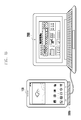
- FIGS. 1A and 1B illustrate a dual monitor system according to an embodiment of the present disclosure.
- the dual monitor system includes a terminal 100 and a computing device 200 as illustrated in FIGS. 1A and 1B .
- the terminal 100 can include a touch screen and display a user interface on the touch screen.
- the computing device 200 can include a screen and display an application program window executed by the computing device on the screen.
- the terminal 100 and the computing device 200 are executed by processors stored in respective memories thereof.
- a dual monitor system connects the terminal 100 and the computing device 200 to allow the terminal 100 and the computing device 200 to exchange signals.
- the terminal 100 and the computing device 200 can be connected to each other through a wire or wirelessly connected to each other by using a wireless network.
- a connection device 300a for connecting one side of the terminal 100 and one side of the screen of the computing device 200 can be further included as illustrated in FIG. 1A
- a connection device 300b for fixing the terminal 100 and connecting the terminal 100 to the computing device 200 can be further included for convenience of the user.
- Embodiments of the present disclosure include all methods of disposing the terminal 100 and the computing device 200 such that the user can have secured view for the touch screen of the terminal 100 and the screen of the computing device 200 can be secured.
- FIG. 2 illustrates a detailed embodiment of the terminal 100 according to an embodiment of the present disclosure.
- the terminal 100 can include a processor 210, a touch screen 220, and an input/output unit 230.
- the processor 210 can control general operations of the terminal 100. That is, the processor 210 can perform a function of providing a user interface to the touch screen 220, receiving a user input through the user interface, and executing a corresponding application program.
- the processor can receive a user input through the touch screen 220 and also receive a user input through the input/output unit 230.
- the touch screen 220 can receive a touch input by the user and also receive an output signal from the processor 210 or the input/output unit 230 and display an output screen. That is, the touch screen 220 can display a user interface and an executed application program and the displayed user interface and application program can be intuitively controlled by a touch input on the touch screen 220 by the user.
- the input/output unit 230 is provided to connect the terminal 100 and an external device, for example, the computing device 200.
- an output signal of the processor 210 can be transmitted to the screen of the computing device 200
- a user input signal by the computing device 200 can be transmitted to the processor 210 of the terminal 100
- an output signal of the computing device 200 can be transmitted to the touch screen 230 of the terminal 100.
- the dual monitor system can include a dual monitor controller 400 for operating the terminal 100 and the computing device 200 in a dual monitor mode.
- the dual monitor controller 400 is connected to the terminal 100 and the computing device 200 to control switching to the dual monitor mode or the single monitor mode.
- the dual monitor controller 400 can be located outside the terminal 100 as illustrated in FIG. 2 , but can be located inside the terminal 100.
- a dual monitor controller 400 which will be described below can be located inside the computing device 200. That is, the dual monitor controller 400 should be interpreted based on the function of the configuration rather than an arrangement of the configuration in the present disclosure.
- FIG. 3 illustrates a detailed embodiment of the computing device 200 according to an embodiment of the present disclosure.
- the computing device 200 can include a main body 310 and peripherals 320 to 340.
- the main body can include a processor 311 for controlling general operations of the computing device 200 and an input/output unit 312 provided to connect the peripherals 320 to 340 and the terminal 100.
- a screen 320, a keyboard 330, and a mouse 340 transmit/receive signals through the input/output unit 312.
- the screen 320 can receive an output signal of the processor 311 and an output signal of the terminal 100 through the input/output unit 312 and display an output screen.
- the keyboard 330 and the mouse 340 are user input means and input signals input by the keyboard 330 and the mouse 340 can be transmitted to the processor 311 and the terminal 100 through the input/output unit 312.
- the dual monitor controller 400 is connected to the terminal 100 and the computing device 200 to control switching to the dual monitor mode or the single monitor mode.
- the dual monitor controller 440 can be located outside or inside the computing device 200 as described above.
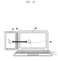
- FIGS. 4A to 4C illustrate that a dual monitor system operates in the dual monitor mode according to an embodiment of the present disclosure.
- the terminal 100 and the computing device 200 are connected through a wire or wirelessly, using any suitable communication technologies including cellular, Wifi, Bluetooth, and Near Field Technologies (NFC).
- the terminal 100 and the computing device 200 are attached to each other by a connection device 300.
- Each of the terminal 100 and the computing device 200 operates in the single monitor mode.
- the terminal 100 displays a user interface 410a on the touch screen.
- the computing device 200 displays one or more application program windows 420a and 430a being executed on the screen.
- the application program window 420a displayed on the screen of the computing device 200 is dragged using a mouse connected to the computing device 200 and moved in a direction in which the terminal 100 is located by a predetermined distance.
- the direction in which the terminal 100 is located can be preset by the user.
- the application program window 420a is dragged by a threshold or more
- switching to the dual monitor mode is made as illustrated in FIG. 4C . That is, the dragged application program window 420 disappears from the screen of the computing device 200 and the application program window 420b is generated on the touch screen of the terminal 100. That is, the touch screen of the terminal 100 operates as one of a dual screen of the computing device 200.
- a user interface 410b of the terminal 100 is copied to the screen of the computing device 200. Accordingly, even in the dual monitor mode, the user can execute a function of the terminal 100 through the user interface 410b of the terminal 100 copied to the screen of the computing device 200.
- a mouse cursor 500 can move on the screen of the computing device 200 and the touch screen of the terminal 100 through a control of the mouse by the user. That is, in the single monitor mode, through a mouse and a keyboard corresponding to input means connected to the computing device 200, a function of the terminal 100 can be executed on the screen of the terminal 100 or a function of the computing device 200 can be executed on the screen of the computing device 200.
- the touch screen of the terminal 100 operates as one of the dual screen of the computing device 200. That is, the mouse cursor 500 can move on the touch screen of the terminal 100 as well as on the screen of the computing device 200, so as to control the application program window executed by the computing device 200. Further, the user interface 410b of the terminal 100 is copied to the screen of the computing device 200. The user can execute the function of the terminal 100 through the copied user interface 410b.
- the application program window executed by the computing device 200 can be controlled on both the touch screen of the terminal and the screen of the computing device 200 and the function of the terminal 100 can be executed on the copied user interface 410b.
- a file displayed on the touch screen of the terminal 100 can be copied to the computing device 200 by dragging the file through a mouse cursor 500 and a file displayed on the screen of the computing device 200 can be copied to the terminal 100 by dragging the file.
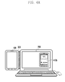
- FIGS. 6A to 6C illustrate a method in which a dual monitor system ends a dual monitor mode according to an embodiment of the present disclosure.
- the dual monitor system is in a state where the dual monitor mode is operated. That is, the terminal 100 is connected to the computing device 200 and the touch screen of the terminal 100 operates as one of the dual screen of the computing device 200.
- the user interface 410b of the terminal 100 is copied to the screen of the computing device 200.
- the user interface 410b of the terminal 100 copied to the screen of the computing device 200 is moved to the terminal 100.
- the copied user interface 410b can be dragged using a mouse. Since the touch screen of the terminal 100 and the screen of the computing device 200 operate in the dual monitor mode, the copied user interface 410b can be moved to the touch screen of the terminal 100 according to the drag.
- the movement of the copied user interface 410 to the touch screen of the terminal 100 is allowed. That is, when the touch screen of the terminal 100 displays a function actually executed by the computing device 200 in the dual monitor mode, it can be preset to not end the dual monitor mode.
- an application program window executed by the computing device 200 is displayed on the touch screen of the terminal 100, if the copied user interface 410 is moved to the touch screen of the terminal 100, the corresponding application program window can be displayed on the screen of the computing device 200.
- the dual monitor mode ends. That is, each of the touch screen of the terminal 100 and the screen of the computing device 200 operates in the single monitor mode.
- FIG. 7 is a flowchart illustrating a dual monitor method according to an embodiment of the present disclosure.
- the terminal 100 and the computing device 200 are connected to each other in step S710.
- Each of the connected terminal 100 and computing device 200 performs a task in the single monitor mode in step S720. That is, the terminal 100 provides a user interface through the touch screen of the terminal 100 and the computing device 200 provides an application program window through the screen of the computing device 200.
- step S730 the terminal 100 and the computing device 200 are switched to the dual monitor mode. Specifically, when the application program window 420a displayed on the screen of the computing device 200 is moved to the touch screen of the terminal 100 in step S731, the user interface 410b of the terminal 100 is copied to the screen of the computing device 200 in step S732. Thereafter, in step S740, the terminal 100 and the computing device 200 perform tasks in the dual monitoring mode.
- step S750 the terminal 100 and the computing device 200 end the dual monitor mode. Specifically, the user interface 410b copied to the screen of the computing device 200 is moved to the touch screen of the terminal 100. Thereafter, in step S760, the terminal 100 and the computing device 200 perform tasks in the single monitor mode.
Landscapes
- Engineering & Computer Science (AREA)
- Theoretical Computer Science (AREA)
- General Engineering & Computer Science (AREA)
- Physics & Mathematics (AREA)
- General Physics & Mathematics (AREA)
- Human Computer Interaction (AREA)
- Computer Hardware Design (AREA)
- Computer Graphics (AREA)
- User Interface Of Digital Computer (AREA)
- Digital Computer Display Output (AREA)
- Telephone Function (AREA)
Applications Claiming Priority (1)
| Application Number | Priority Date | Filing Date | Title |
|---|---|---|---|
| KR20130105175A KR20150026403A (ko) | 2013-09-03 | 2013-09-03 | 듀얼 모니터링 시스템 및 방법 |
Publications (3)
| Publication Number | Publication Date |
|---|---|
| EP2851785A2 true EP2851785A2 (de) | 2015-03-25 |
| EP2851785A3 EP2851785A3 (de) | 2015-07-01 |
| EP2851785B1 EP2851785B1 (de) | 2018-06-13 |
Family
ID=51535315
Family Applications (1)
| Application Number | Title | Priority Date | Filing Date |
|---|---|---|---|
| EP14183046.3A Not-in-force EP2851785B1 (de) | 2013-09-03 | 2014-09-01 | System und Verfahren mit zwei Bildschirmen |
Country Status (3)
| Country | Link |
|---|---|
| US (1) | US20150067550A1 (de) |
| EP (1) | EP2851785B1 (de) |
| KR (1) | KR20150026403A (de) |
Families Citing this family (14)
| Publication number | Priority date | Publication date | Assignee | Title |
|---|---|---|---|---|
| USD753142S1 (en) * | 2013-12-30 | 2016-04-05 | Samsung Electronics Co., Ltd. | Display screen or portion thereof with graphical user interface |
| USD760733S1 (en) * | 2013-12-30 | 2016-07-05 | Samsung Electronics Co., Ltd. | Display screen or portion thereof with graphical user interface |
| USD753143S1 (en) * | 2013-12-30 | 2016-04-05 | Samsung Electronics Co., Ltd. | Display screen or portion thereof with graphical user interface |
| USD752606S1 (en) * | 2013-12-30 | 2016-03-29 | Samsung Electronics Co., Ltd. | Display screen or portion thereof with graphical user interface |
| KR102364674B1 (ko) * | 2015-04-27 | 2022-02-18 | 엘지전자 주식회사 | 디스플레이 디바이스 및 그 제어 방법 |
| CN105426143A (zh) * | 2015-10-28 | 2016-03-23 | 上海创客科技有限公司 | 智能终端显示装置兼容系统及方法 |
| CN109871188B (zh) * | 2017-12-04 | 2023-04-07 | 西安中兴新软件有限责任公司 | 一种屏幕显示控制方法和装置、及终端 |
| US11416130B2 (en) | 2019-10-01 | 2022-08-16 | Microsoft Technology Licensing, Llc | Moving applications on multi-screen computing device |
| US11201962B2 (en) | 2019-10-01 | 2021-12-14 | Microsoft Technology Licensing, Llc | Calling on a multi-display device |
| US11561587B2 (en) | 2019-10-01 | 2023-01-24 | Microsoft Technology Licensing, Llc | Camera and flashlight operation in hinged device |
| US11042222B1 (en) | 2019-12-16 | 2021-06-22 | Microsoft Technology Licensing, Llc | Sub-display designation and sharing |
| US11487423B2 (en) | 2019-12-16 | 2022-11-01 | Microsoft Technology Licensing, Llc | Sub-display input areas and hidden inputs |
| US11093046B2 (en) * | 2019-12-16 | 2021-08-17 | Microsoft Technology Licensing, Llc | Sub-display designation for remote content source device |
| US11404028B2 (en) | 2019-12-16 | 2022-08-02 | Microsoft Technology Licensing, Llc | Sub-display notification handling |
Family Cites Families (5)
| Publication number | Priority date | Publication date | Assignee | Title |
|---|---|---|---|---|
| KR100636184B1 (ko) * | 2004-10-13 | 2006-10-19 | 삼성전자주식회사 | 정보 처리 장치의 표시 화면에 표시되는 표시 윈도우의위치 제어 방법 및 위치 제어 장치 |
| CN101354639A (zh) * | 2007-07-25 | 2009-01-28 | 联想(北京)有限公司 | 在终端之间操作对象的方法及终端 |
| US9280254B2 (en) * | 2008-01-22 | 2016-03-08 | Bluebeam Software, Inc. | Method of synchronizing multiple views of multiple displayed documents |
| US8522308B2 (en) * | 2010-02-11 | 2013-08-27 | Verizon Patent And Licensing Inc. | Systems and methods for providing a spatial-input-based multi-user shared display experience |
| CN103246433A (zh) * | 2013-05-06 | 2013-08-14 | 苏州三星电子电脑有限公司 | 屏幕自定义分窗口显示控制方法 |
-
2013
- 2013-09-03 KR KR20130105175A patent/KR20150026403A/ko not_active Ceased
-
2014
- 2014-09-01 EP EP14183046.3A patent/EP2851785B1/de not_active Not-in-force
- 2014-09-03 US US14/476,621 patent/US20150067550A1/en not_active Abandoned
Non-Patent Citations (1)
| Title |
|---|
| None |
Also Published As
| Publication number | Publication date |
|---|---|
| US20150067550A1 (en) | 2015-03-05 |
| KR20150026403A (ko) | 2015-03-11 |
| EP2851785A3 (de) | 2015-07-01 |
| EP2851785B1 (de) | 2018-06-13 |
Similar Documents
| Publication | Publication Date | Title |
|---|---|---|
| EP2851785A2 (de) | System und Verfahren mit zwei Bildschirmen | |
| KR102858208B1 (ko) | 디스플레이 기기, 모바일 기기, 그에 따른 디스플레이 기기를 통해 수행되는 영상 통화 방법 및 그에 따른 모바일 기기를 통해 수행되는 영상 통화 방법 | |
| KR102574183B1 (ko) | 디스플레이를 제어하는 전자 장치 및 방법 | |
| KR102571369B1 (ko) | 디스플레이 제어 방법, 저장 매체 및 전자 장치 | |
| EP2778865B1 (de) | Eingangssteuerverfahren und elektronische Vorrichtung zur Unterstützung davon | |
| CN105610471B (zh) | 无线数据输入和输出方法和设备 | |
| KR102443069B1 (ko) | 어플리케이션을 실행하기 위한 장치 및 방법 | |
| US11353968B2 (en) | Electronic device and control method for providing display coordinates on an external display device | |
| TWI528266B (zh) | 電子裝置及螢幕內容分享方法 | |
| WO2019024898A1 (zh) | 文件传输显示控制方法、装置及相应的终端 | |
| EP2806359B1 (de) | Verfahren und Vorrichtung zur Anwendungsverwaltung | |
| KR20180089229A (ko) | 디스플레이 제어 방법, 저장 매체 및 전자 장치 | |
| KR102629341B1 (ko) | 멀티태스킹을 위한 인터페이스 제공 방법 및 이를 구현하는 전자 장치 | |
| EP2824551A1 (de) | Verfahren, vorrichtung und system zur steuerung eines computerendgeräts | |
| KR20180015532A (ko) | 디스플레이 제어 방법, 저장 매체 및 전자 장치 | |
| CN106462313A (zh) | 用于管理显示对象的方法和电子设备 | |
| KR101932086B1 (ko) | 카메라 제어 방법 및 휴대 장치 | |
| KR20150022599A (ko) | 전자장치의 환경 설정 방법 및 장치 | |
| CN105975190B (zh) | 一种图形界面的处理方法、装置及系统 | |
| KR20180110452A (ko) | 외부 장치를 이용한 화면 출력 방법 및 이를 지원하는 전자 장치 | |
| CN104981767A (zh) | 受控头戴式计算机显示器 | |
| EP3938863B1 (de) | System, verfahren, computerprogramm, mobiles gerät und kit zum betreiben einer vorrichtung mit niedriger rechenleistung | |
| CN110865743A (zh) | 任务管理方法和终端设备 | |
| KR20140123818A (ko) | 오디오 출력 제어 방법 및 이를 지원하는 장치 | |
| JP2014038514A (ja) | 携帯型の情報機器およびコンピュータープログラム |
Legal Events
| Date | Code | Title | Description |
|---|---|---|---|
| PUAI | Public reference made under article 153(3) epc to a published international application that has entered the european phase |
Free format text: ORIGINAL CODE: 0009012 |
|
| 17P | Request for examination filed |
Effective date: 20140901 |
|
| AK | Designated contracting states |
Kind code of ref document: A2 Designated state(s): AL AT BE BG CH CY CZ DE DK EE ES FI FR GB GR HR HU IE IS IT LI LT LU LV MC MK MT NL NO PL PT RO RS SE SI SK SM TR |
|
| AX | Request for extension of the european patent |
Extension state: BA ME |
|
| PUAL | Search report despatched |
Free format text: ORIGINAL CODE: 0009013 |
|
| AK | Designated contracting states |
Kind code of ref document: A3 Designated state(s): AL AT BE BG CH CY CZ DE DK EE ES FI FR GB GR HR HU IE IS IT LI LT LU LV MC MK MT NL NO PL PT RO RS SE SI SK SM TR |
|
| AX | Request for extension of the european patent |
Extension state: BA ME |
|
| RIC1 | Information provided on ipc code assigned before grant |
Ipc: G06F 3/14 20060101AFI20150526BHEP |
|
| R17P | Request for examination filed (corrected) |
Effective date: 20151231 |
|
| RBV | Designated contracting states (corrected) |
Designated state(s): AL AT BE BG CH CY CZ DE DK EE ES FI FR GB GR HR HU IE IS IT LI LT LU LV MC MK MT NL NO PL PT RO RS SE SI SK SM TR |
|
| 17Q | First examination report despatched |
Effective date: 20160502 |
|
| GRAP | Despatch of communication of intention to grant a patent |
Free format text: ORIGINAL CODE: EPIDOSNIGR1 |
|
| STAA | Information on the status of an ep patent application or granted ep patent |
Free format text: STATUS: GRANT OF PATENT IS INTENDED |
|
| INTG | Intention to grant announced |
Effective date: 20171218 |
|
| GRAS | Grant fee paid |
Free format text: ORIGINAL CODE: EPIDOSNIGR3 |
|
| GRAA | (expected) grant |
Free format text: ORIGINAL CODE: 0009210 |
|
| STAA | Information on the status of an ep patent application or granted ep patent |
Free format text: STATUS: THE PATENT HAS BEEN GRANTED |
|
| AK | Designated contracting states |
Kind code of ref document: B1 Designated state(s): AL AT BE BG CH CY CZ DE DK EE ES FI FR GB GR HR HU IE IS IT LI LT LU LV MC MK MT NL NO PL PT RO RS SE SI SK SM TR |
|
| REG | Reference to a national code |
Ref country code: GB Ref legal event code: FG4D |
|
| REG | Reference to a national code |
Ref country code: CH Ref legal event code: EP Ref country code: AT Ref legal event code: REF Ref document number: 1009151 Country of ref document: AT Kind code of ref document: T Effective date: 20180615 |
|
| REG | Reference to a national code |
Ref country code: IE Ref legal event code: FG4D |
|
| REG | Reference to a national code |
Ref country code: DE Ref legal event code: R096 Ref document number: 602014026889 Country of ref document: DE |
|
| REG | Reference to a national code |
Ref country code: NL Ref legal event code: FP |
|
| REG | Reference to a national code |
Ref country code: LT Ref legal event code: MG4D |
|
| PG25 | Lapsed in a contracting state [announced via postgrant information from national office to epo] |
Ref country code: ES Free format text: LAPSE BECAUSE OF FAILURE TO SUBMIT A TRANSLATION OF THE DESCRIPTION OR TO PAY THE FEE WITHIN THE PRESCRIBED TIME-LIMIT Effective date: 20180613 Ref country code: LT Free format text: LAPSE BECAUSE OF FAILURE TO SUBMIT A TRANSLATION OF THE DESCRIPTION OR TO PAY THE FEE WITHIN THE PRESCRIBED TIME-LIMIT Effective date: 20180613 Ref country code: NO Free format text: LAPSE BECAUSE OF FAILURE TO SUBMIT A TRANSLATION OF THE DESCRIPTION OR TO PAY THE FEE WITHIN THE PRESCRIBED TIME-LIMIT Effective date: 20180913 Ref country code: CY Free format text: LAPSE BECAUSE OF FAILURE TO SUBMIT A TRANSLATION OF THE DESCRIPTION OR TO PAY THE FEE WITHIN THE PRESCRIBED TIME-LIMIT Effective date: 20180613 Ref country code: SE Free format text: LAPSE BECAUSE OF FAILURE TO SUBMIT A TRANSLATION OF THE DESCRIPTION OR TO PAY THE FEE WITHIN THE PRESCRIBED TIME-LIMIT Effective date: 20180613 Ref country code: FI Free format text: LAPSE BECAUSE OF FAILURE TO SUBMIT A TRANSLATION OF THE DESCRIPTION OR TO PAY THE FEE WITHIN THE PRESCRIBED TIME-LIMIT Effective date: 20180613 Ref country code: BG Free format text: LAPSE BECAUSE OF FAILURE TO SUBMIT A TRANSLATION OF THE DESCRIPTION OR TO PAY THE FEE WITHIN THE PRESCRIBED TIME-LIMIT Effective date: 20180913 |
|
| PG25 | Lapsed in a contracting state [announced via postgrant information from national office to epo] |
Ref country code: GR Free format text: LAPSE BECAUSE OF FAILURE TO SUBMIT A TRANSLATION OF THE DESCRIPTION OR TO PAY THE FEE WITHIN THE PRESCRIBED TIME-LIMIT Effective date: 20180914 Ref country code: RS Free format text: LAPSE BECAUSE OF FAILURE TO SUBMIT A TRANSLATION OF THE DESCRIPTION OR TO PAY THE FEE WITHIN THE PRESCRIBED TIME-LIMIT Effective date: 20180613 Ref country code: LV Free format text: LAPSE BECAUSE OF FAILURE TO SUBMIT A TRANSLATION OF THE DESCRIPTION OR TO PAY THE FEE WITHIN THE PRESCRIBED TIME-LIMIT Effective date: 20180613 Ref country code: HR Free format text: LAPSE BECAUSE OF FAILURE TO SUBMIT A TRANSLATION OF THE DESCRIPTION OR TO PAY THE FEE WITHIN THE PRESCRIBED TIME-LIMIT Effective date: 20180613 |
|
| REG | Reference to a national code |
Ref country code: AT Ref legal event code: MK05 Ref document number: 1009151 Country of ref document: AT Kind code of ref document: T Effective date: 20180613 |
|
| PG25 | Lapsed in a contracting state [announced via postgrant information from national office to epo] |
Ref country code: RO Free format text: LAPSE BECAUSE OF FAILURE TO SUBMIT A TRANSLATION OF THE DESCRIPTION OR TO PAY THE FEE WITHIN THE PRESCRIBED TIME-LIMIT Effective date: 20180613 Ref country code: CZ Free format text: LAPSE BECAUSE OF FAILURE TO SUBMIT A TRANSLATION OF THE DESCRIPTION OR TO PAY THE FEE WITHIN THE PRESCRIBED TIME-LIMIT Effective date: 20180613 Ref country code: SK Free format text: LAPSE BECAUSE OF FAILURE TO SUBMIT A TRANSLATION OF THE DESCRIPTION OR TO PAY THE FEE WITHIN THE PRESCRIBED TIME-LIMIT Effective date: 20180613 Ref country code: AT Free format text: LAPSE BECAUSE OF FAILURE TO SUBMIT A TRANSLATION OF THE DESCRIPTION OR TO PAY THE FEE WITHIN THE PRESCRIBED TIME-LIMIT Effective date: 20180613 Ref country code: IS Free format text: LAPSE BECAUSE OF FAILURE TO SUBMIT A TRANSLATION OF THE DESCRIPTION OR TO PAY THE FEE WITHIN THE PRESCRIBED TIME-LIMIT Effective date: 20181013 Ref country code: PL Free format text: LAPSE BECAUSE OF FAILURE TO SUBMIT A TRANSLATION OF THE DESCRIPTION OR TO PAY THE FEE WITHIN THE PRESCRIBED TIME-LIMIT Effective date: 20180613 Ref country code: EE Free format text: LAPSE BECAUSE OF FAILURE TO SUBMIT A TRANSLATION OF THE DESCRIPTION OR TO PAY THE FEE WITHIN THE PRESCRIBED TIME-LIMIT Effective date: 20180613 |
|
| PG25 | Lapsed in a contracting state [announced via postgrant information from national office to epo] |
Ref country code: SM Free format text: LAPSE BECAUSE OF FAILURE TO SUBMIT A TRANSLATION OF THE DESCRIPTION OR TO PAY THE FEE WITHIN THE PRESCRIBED TIME-LIMIT Effective date: 20180613 Ref country code: IT Free format text: LAPSE BECAUSE OF FAILURE TO SUBMIT A TRANSLATION OF THE DESCRIPTION OR TO PAY THE FEE WITHIN THE PRESCRIBED TIME-LIMIT Effective date: 20180613 |
|
| REG | Reference to a national code |
Ref country code: DE Ref legal event code: R097 Ref document number: 602014026889 Country of ref document: DE |
|
| PLBE | No opposition filed within time limit |
Free format text: ORIGINAL CODE: 0009261 |
|
| STAA | Information on the status of an ep patent application or granted ep patent |
Free format text: STATUS: NO OPPOSITION FILED WITHIN TIME LIMIT |
|
| PG25 | Lapsed in a contracting state [announced via postgrant information from national office to epo] |
Ref country code: MC Free format text: LAPSE BECAUSE OF FAILURE TO SUBMIT A TRANSLATION OF THE DESCRIPTION OR TO PAY THE FEE WITHIN THE PRESCRIBED TIME-LIMIT Effective date: 20180613 |
|
| REG | Reference to a national code |
Ref country code: CH Ref legal event code: PL |
|
| 26N | No opposition filed |
Effective date: 20190314 |
|
| PG25 | Lapsed in a contracting state [announced via postgrant information from national office to epo] |
Ref country code: DK Free format text: LAPSE BECAUSE OF FAILURE TO SUBMIT A TRANSLATION OF THE DESCRIPTION OR TO PAY THE FEE WITHIN THE PRESCRIBED TIME-LIMIT Effective date: 20180613 Ref country code: SI Free format text: LAPSE BECAUSE OF FAILURE TO SUBMIT A TRANSLATION OF THE DESCRIPTION OR TO PAY THE FEE WITHIN THE PRESCRIBED TIME-LIMIT Effective date: 20180613 |
|
| REG | Reference to a national code |
Ref country code: BE Ref legal event code: MM Effective date: 20180930 |
|
| REG | Reference to a national code |
Ref country code: IE Ref legal event code: MM4A |
|
| PG25 | Lapsed in a contracting state [announced via postgrant information from national office to epo] |
Ref country code: LU Free format text: LAPSE BECAUSE OF NON-PAYMENT OF DUE FEES Effective date: 20180901 |
|
| PG25 | Lapsed in a contracting state [announced via postgrant information from national office to epo] |
Ref country code: IE Free format text: LAPSE BECAUSE OF NON-PAYMENT OF DUE FEES Effective date: 20180901 |
|
| PG25 | Lapsed in a contracting state [announced via postgrant information from national office to epo] |
Ref country code: LI Free format text: LAPSE BECAUSE OF NON-PAYMENT OF DUE FEES Effective date: 20180930 Ref country code: CH Free format text: LAPSE BECAUSE OF NON-PAYMENT OF DUE FEES Effective date: 20180930 Ref country code: FR Free format text: LAPSE BECAUSE OF NON-PAYMENT OF DUE FEES Effective date: 20180930 Ref country code: BE Free format text: LAPSE BECAUSE OF NON-PAYMENT OF DUE FEES Effective date: 20180930 |
|
| PGFP | Annual fee paid to national office [announced via postgrant information from national office to epo] |
Ref country code: NL Payment date: 20190821 Year of fee payment: 6 |
|
| PGFP | Annual fee paid to national office [announced via postgrant information from national office to epo] |
Ref country code: DE Payment date: 20190820 Year of fee payment: 6 |
|
| PG25 | Lapsed in a contracting state [announced via postgrant information from national office to epo] |
Ref country code: AL Free format text: LAPSE BECAUSE OF FAILURE TO SUBMIT A TRANSLATION OF THE DESCRIPTION OR TO PAY THE FEE WITHIN THE PRESCRIBED TIME-LIMIT Effective date: 20180613 |
|
| PGFP | Annual fee paid to national office [announced via postgrant information from national office to epo] |
Ref country code: GB Payment date: 20190821 Year of fee payment: 6 |
|
| PG25 | Lapsed in a contracting state [announced via postgrant information from national office to epo] |
Ref country code: MT Free format text: LAPSE BECAUSE OF NON-PAYMENT OF DUE FEES Effective date: 20180901 |
|
| PG25 | Lapsed in a contracting state [announced via postgrant information from national office to epo] |
Ref country code: TR Free format text: LAPSE BECAUSE OF FAILURE TO SUBMIT A TRANSLATION OF THE DESCRIPTION OR TO PAY THE FEE WITHIN THE PRESCRIBED TIME-LIMIT Effective date: 20180613 |
|
| PG25 | Lapsed in a contracting state [announced via postgrant information from national office to epo] |
Ref country code: HU Free format text: LAPSE BECAUSE OF FAILURE TO SUBMIT A TRANSLATION OF THE DESCRIPTION OR TO PAY THE FEE WITHIN THE PRESCRIBED TIME-LIMIT; INVALID AB INITIO Effective date: 20140901 Ref country code: PT Free format text: LAPSE BECAUSE OF FAILURE TO SUBMIT A TRANSLATION OF THE DESCRIPTION OR TO PAY THE FEE WITHIN THE PRESCRIBED TIME-LIMIT Effective date: 20180613 |
|
| PG25 | Lapsed in a contracting state [announced via postgrant information from national office to epo] |
Ref country code: MK Free format text: LAPSE BECAUSE OF NON-PAYMENT OF DUE FEES Effective date: 20180613 |
|
| REG | Reference to a national code |
Ref country code: DE Ref legal event code: R119 Ref document number: 602014026889 Country of ref document: DE |
|
| REG | Reference to a national code |
Ref country code: NL Ref legal event code: MM Effective date: 20201001 |
|
| GBPC | Gb: european patent ceased through non-payment of renewal fee |
Effective date: 20200901 |
|
| PG25 | Lapsed in a contracting state [announced via postgrant information from national office to epo] |
Ref country code: NL Free format text: LAPSE BECAUSE OF NON-PAYMENT OF DUE FEES Effective date: 20201001 |
|
| PG25 | Lapsed in a contracting state [announced via postgrant information from national office to epo] |
Ref country code: DE Free format text: LAPSE BECAUSE OF NON-PAYMENT OF DUE FEES Effective date: 20210401 |
|
| PG25 | Lapsed in a contracting state [announced via postgrant information from national office to epo] |
Ref country code: GB Free format text: LAPSE BECAUSE OF NON-PAYMENT OF DUE FEES Effective date: 20200901 |