EP2851873B1 - Clé RFID, notamment unité de transpondeur RFID, dispositif et procédé de programmation et dispositif et procédé de verrouillage présentant un verrou RFID et système le composant - Google Patents
Clé RFID, notamment unité de transpondeur RFID, dispositif et procédé de programmation et dispositif et procédé de verrouillage présentant un verrou RFID et système le composant Download PDFInfo
- Publication number
- EP2851873B1 EP2851873B1 EP14177319.2A EP14177319A EP2851873B1 EP 2851873 B1 EP2851873 B1 EP 2851873B1 EP 14177319 A EP14177319 A EP 14177319A EP 2851873 B1 EP2851873 B1 EP 2851873B1
- Authority
- EP
- European Patent Office
- Prior art keywords
- rfid
- lock
- key
- time
- coupling
- Prior art date
- Legal status (The legal status is an assumption and is not a legal conclusion. Google has not performed a legal analysis and makes no representation as to the accuracy of the status listed.)
- Active
Links
Images




Classifications
-
- G—PHYSICS
- G07—CHECKING-DEVICES
- G07C—TIME OR ATTENDANCE REGISTERS; REGISTERING OR INDICATING THE WORKING OF MACHINES; GENERATING RANDOM NUMBERS; VOTING OR LOTTERY APPARATUS; ARRANGEMENTS, SYSTEMS OR APPARATUS FOR CHECKING NOT PROVIDED FOR ELSEWHERE
- G07C9/00—Individual registration on entry or exit
- G07C9/00174—Electronically operated locks; Circuits therefor; Nonmechanical keys therefor, e.g. passive or active electrical keys or other data carriers without mechanical keys
- G07C9/00857—Electronically operated locks; Circuits therefor; Nonmechanical keys therefor, e.g. passive or active electrical keys or other data carriers without mechanical keys where the code of the data carrier can be programmed
-
- G—PHYSICS
- G07—CHECKING-DEVICES
- G07C—TIME OR ATTENDANCE REGISTERS; REGISTERING OR INDICATING THE WORKING OF MACHINES; GENERATING RANDOM NUMBERS; VOTING OR LOTTERY APPARATUS; ARRANGEMENTS, SYSTEMS OR APPARATUS FOR CHECKING NOT PROVIDED FOR ELSEWHERE
- G07C9/00—Individual registration on entry or exit
- G07C9/00174—Electronically operated locks; Circuits therefor; Nonmechanical keys therefor, e.g. passive or active electrical keys or other data carriers without mechanical keys
- G07C9/00309—Electronically operated locks; Circuits therefor; Nonmechanical keys therefor, e.g. passive or active electrical keys or other data carriers without mechanical keys operated with bidirectional data transmission between data carrier and locks
-
- G—PHYSICS
- G07—CHECKING-DEVICES
- G07C—TIME OR ATTENDANCE REGISTERS; REGISTERING OR INDICATING THE WORKING OF MACHINES; GENERATING RANDOM NUMBERS; VOTING OR LOTTERY APPARATUS; ARRANGEMENTS, SYSTEMS OR APPARATUS FOR CHECKING NOT PROVIDED FOR ELSEWHERE
- G07C9/00—Individual registration on entry or exit
- G07C9/00174—Electronically operated locks; Circuits therefor; Nonmechanical keys therefor, e.g. passive or active electrical keys or other data carriers without mechanical keys
- G07C2009/00968—Electronically operated locks; Circuits therefor; Nonmechanical keys therefor, e.g. passive or active electrical keys or other data carriers without mechanical keys shape of the data carrier
-
- G—PHYSICS
- G07—CHECKING-DEVICES
- G07C—TIME OR ATTENDANCE REGISTERS; REGISTERING OR INDICATING THE WORKING OF MACHINES; GENERATING RANDOM NUMBERS; VOTING OR LOTTERY APPARATUS; ARRANGEMENTS, SYSTEMS OR APPARATUS FOR CHECKING NOT PROVIDED FOR ELSEWHERE
- G07C2209/00—Indexing scheme relating to groups G07C9/00 - G07C9/38
- G07C2209/08—With time considerations, e.g. temporary activation, valid time window or time limitations
-
- G—PHYSICS
- G07—CHECKING-DEVICES
- G07C—TIME OR ATTENDANCE REGISTERS; REGISTERING OR INDICATING THE WORKING OF MACHINES; GENERATING RANDOM NUMBERS; VOTING OR LOTTERY APPARATUS; ARRANGEMENTS, SYSTEMS OR APPARATUS FOR CHECKING NOT PROVIDED FOR ELSEWHERE
- G07C9/00—Individual registration on entry or exit
- G07C9/00174—Electronically operated locks; Circuits therefor; Nonmechanical keys therefor, e.g. passive or active electrical keys or other data carriers without mechanical keys
- G07C9/00896—Electronically operated locks; Circuits therefor; Nonmechanical keys therefor, e.g. passive or active electrical keys or other data carriers without mechanical keys specially adapted for particular uses
- G07C9/00904—Electronically operated locks; Circuits therefor; Nonmechanical keys therefor, e.g. passive or active electrical keys or other data carriers without mechanical keys specially adapted for particular uses for hotels, motels, office buildings or the like
Definitions
- the invention relates to a system with at least one RFID key, in particular an RFID transponder unit, for communication with a locking device with an RFID lock for access or access control and with an RFID programming device for programming RFID keys, in particular RFID transponder units , according to the preamble of claim 1. Furthermore, the invention relates to a locking method for controlling an access or an access according to the preamble of claim 10.
- Access controls for lockers with RFID technology are known from modern swimming pools.
- a swimming pool visitor is given an RFID key, in particular an RFID transponder unit, when entering the swimming pool - usually after paying an entrance fee.
- the RFID key or the RFID transponder unit enables the swimming pool visitor to lock and unlock a locker in the swimming pool. In this way, the swimming pool visitor can leave the items that are not needed in the locked locker while swimming.
- the RFID key or the RFID transponder unit is not linked to a specific locker.
- the swimming pool visitor brings the RFID key, in particular the RFID transponder unit, into the area of an antenna of a locking device with an RFID lock, which is attached to a locker door of a selected locker.
- the RFID lock and the RFID key or the RFID transponder unit mutually exchange their identity or identify each other.
- the selected locker is free and no other locker has yet been locked with the RFID key, in particular the RFID transponder unit the RFID key, in particular the RFID transponder unit, and the RFID lock, so that the swimming pool visitor can lock the selected locker.
- the coupling which is noted on the RFID key, in particular the RFID transponder unit, and the RFID lock, it is achieved on the one hand that the locker is marked as occupied and thus no new coupling with another RFID key or a carries out another RFID transponder unit.
- the coupling noted on the RFID key, in particular the RFID transponder unit ensures that the RFID key or the RFID transponder unit cannot lock another locker because it has already locked a locker.
- the swimming pool visitor After swimming, the swimming pool visitor holds the RFID key or the RFID transponder unit in front of the locked locker.
- the RFID lock and the RFID key or the RFID transponder unit in turn mutually exchange their identity or identify each other and also establish their coupling, whereby the locker can be unlocked or opened and the coupling is released at the same time.
- the coupling which in turn is noted on the RFID key, in particular the RFID transponder unit, and the RFID lock, it is achieved on the one hand that the locker is marked as free and for a new coupling with an RFID key or .
- an RFID transponder unit is ready. On the other hand, this ensures that the RFID key or the RFID transponder unit can lock another free, that is, not coupled, or the same locker.
- the RFID key or the RFID transponder unit is handed over at the entrance.
- a hotel guest is given an RFID key, in particular the RFID transponder unit, in the form of a card or a bracelet during the check-in process at the hotel reception.
- the RFID key in particular the RFID transponder unit, enables the guest to access a hotel room that has a locking device with an RFID lock.
- the RFID key is returned and the staff at the reception releases the link between the RFID key or the RFID transponder unit and the RFID lock via the network.
- the staff at the reception has the option of to decouple the locking system and the lost RFID key or RFID transponder units via the network connection so that the lost RFID key or RFID transponder units no longer allow access to the hotel room.
- DE 10 2004 052 560 A1 shows a card deposit lock for locking a locker, for example, and a method or operating system for operating a system such as a sports facility or a fitness center.
- a personal identification code is initially generated on a central unit or on a server for a visitor when purchasing an admission ticket and then also stored on the admission ticket. The visitor can then choose any locker and insert his or her entry ticket into the card deposit lock installed in the locker.
- the identification code is read from the entrance ticket by electronics in the card deposit lock and written on an associated RFID element, for example in the form of a bracelet, which can be removed from the locker door.
- the RFID organ then serves, on the one hand, to lock or unlock the locker.
- the readable identification code in the bracelet can be used to immediately record if the visitor uses systems or services with his RFID key that are not included in the entrance fee, for example are.
- payment in a restaurant of the facility can be made by means of the RFID organ, in that the visitor shows his RFID organ with the identification code stored on it and has it read out so that amounts to be paid are assigned to the identification code on the central server.
- stations connected to the server are provided that record services or product purchases and - assigned to the respective identification code read out - transmitted to the central unit, where they are added up.
- a user time can also be recorded, so that a postage fee has to be paid if a system is used for too long.
- DE 60 2005 005641 T2 shows an electronically programmable locking system in which every user can use all available locks without having to be assigned one beforehand.
- the system consists of locks and keys with a read and write function based on RFID technology.
- the locks that make up this system are not connected to each other or to a central unit, and each key can be used on all locks that are not already occupied. After a key has been used on a lock, it cannot be used on any other lock in the same system.
- the locks have a clock chip to check an expiration date on the key.
- the present invention is based on the problem of finding RFID locks and RFID keys, in particular RFID transponder units, for applications in which the coupling of an RFID key, in particular an RFID transponder unit, to an RFID lock also occurs unlocking a locking device with an RFID lock can persist. Furthermore, a network connection to the RFID locks should not be required for this purpose, so that the installation effort - even with subsequent installation in an existing system - can be kept low. In addition, it should be possible to establish and release the coupling without additional personnel expenditure.
- this problem is solved by a system with at least one RFID key, in particular an RFID transponder unit, for communication with a locking device, at least one locking device with an RFID lock for access control and at least one RFID programming device for programming RFID Keys, in particular RFID transponder units, solved according to claim 1.
- the problem is solved by a locking method for controlling access or access according to claim 10.
- the RFID key according to the invention in particular the RFID transponder unit, is used for communication with at least one locking device, that is to say with one or more locking devices, with one or in each case with an RFID lock. Furthermore, the RFID key according to the invention, in particular the RFID transponder unit, is also used for communication with at least one RFID programming device, that is to say with one or more RFID programming devices.
- the RFID key in particular the RFID transponder unit, has an identification means with which at least one of predefined RFID locks can be identified.
- Predefined RFID locks here in particular only include RFID locks that are standardized according to one or more specified standards, such as ISO 15963, and have certain unique identifiers or serial numbers (UIDs).
- the identification means of the RFID key, in particular the RFID transponder unit is thus limited to a certain number of RFID locks that can be identified by the RFID key, in particular the RFID transponder unit.
- the identification means also serve to identify one or more RFID programming devices from predefined RFID programming devices.
- the predefined RFID programming devices here also include in particular only RFID programming devices that are standardized according to one or more specified standards and have certain unique identifiers or serial numbers (UIDs).
- the RFID key according to the invention in particular the RFID transponder unit, has a coupling means, the coupling means serving to couple an identified RFID lock to the RFID key, in particular the RFID transponder unit, or a coupling between the RFID -Key, in particular the RFID transponder unit, and the identified RFID lock.
- Coupling here means establishing a connection, in particular the RFID key or the RFID transponder unit, with the identified RFID lock by noting the unique identifier (UID) or another non-confusing identifier of the RFID lock in the RFID key, in particular the RFID transponder unit, or in a memory of the RFID key or the RFID transponder.
- UID unique identifier
- the RFID key according to the invention in particular the RFID transponder unit, also comprises a receiving means for receiving a radio signal with a period or point in time from an RFID programming device identified with the identification means and a storage means for storing the received period or point in time. If the RFID key or the RFID transponder unit is accordingly brought into the area of an RFID programming device, the RFID programming device is one of the predetermined programming devices and the RFID programming device is therefore identified by the RFID key, in particular the RFID transponder unit , a time information sent by the RFID programming device with a radio signal or a time period information sent by the RFID programming device with a radio signal is received by the receiving means of the RFID key and on the RFID key, in particular the RFID transponder unit, or in the memory of the RFID key, in particular the RFID transponder unit, is stored.
- the RFID key has a transmission means for transmitting a radio signal with the stored period or time information.
- This radio signal is sent by the RFID key, in particular the RFID transponder unit, during or after the coupling with an RFID lock to the coupled RFID lock.
- the invention further comprises a locking device with an RFID lock for access or access control.
- the locking device is used in particular to control access to the contents of a container, for example a cabinet.
- the locking device has an identification means for identifying at least one of predefined RFID keys or RFID transponder units.
- Predefined RFID keys include here, analogously to what was stated above for predefined RFID locks, in particular RFID keys or RFID transponder units, which are standardized according to one or more specified standards, such as ISO 15963, and certain have unique identifiers (UIDs). Accordingly, the number of RFID keys, in particular the RFID transponder units, which can be identified by the identification means of the locking device, is limited by the requirements mentioned last.
- the locking device according to the invention also has a coupling means.
- the coupling means is used to couple and uncouple the RFID lock to or with an RFID key, in particular an RFID transponder unit.
- the coupling means is designed to allow only one coupling of the RFID lock with an RFID key, in particular an RFID transponder unit, at any one time. This means that the RFID lock cannot establish, note or save a connection to two RFID keys or RFID transponder units at the same time.
- the RFID lock has a receiving means with which a radio signal with a period or point in time can be received from an identified RFID key or an RFID transponder unit.
- the receiving means is designed to receive the radio signal with a period or time information only during or once after the coupling with the RFID key, in particular the RFID transponder unit. The reception of the radio signal with a period or point in time is therefore dependent on the coupling and is carried out directly in the communication process of the RFID key, in particular the RFID transponder unit, and the RFID lock with which the coupling takes place, from the RFID key, in particular the RFID transponder unit, sent or received by the RFID lock.
- the RFID lock has a time control with which, on the one hand, the coupling is noted for a duration that is dependent on the period or time of the received period or time information, and on the other hand, the locking with the locking device is only released in the event that the Coupling is still noted.
- the coupling is noted here, for example, by storing in the RFID lock that a coupling has taken place, whereby an identifier, e.g. the unique identifier (UID) of the coupled RFID key or the RFID transponder unit, is also stored in the RFID lock he follows.
- an identifier e.g. the unique identifier (UID) of the coupled RFID key or the RFID transponder unit
- this note of the coupling is dependent on the period of the received period information or on the time of the received point in time information.
- the duration for which the RFID lock is coupled to or to an RFID key, in particular to an RFID transponder unit is determined in particular by the period of the period of time information received or the point in time of the time information received.
- the RFID lock releases the coupling to the RFID key or to the RFID transponder unit, whereby, according to a particular embodiment of the invention, the coupling is maintained, i.e. noted , is until the locking device is unlocked after the expiry of the period or after reaching the point in time in the case of a locked state.
- the time control serves to enable locking with the locking device only in the event, that is to say to allow it, when the coupling is still noted, that is, it continues to exist or is stored. After expiry of the period of the received period information or after reaching the point in time of the received point in time information, locking or locking with the locking device is no longer possible.
- the time control of the locking device has a test means that checks whether a coupling is noted or not, and a release means that prohibits or allows locking based on the test result of the test means.
- the invention also has an RFID programming device, in particular an RFID programming terminal, for programming RFID keys, in particular RFID transponder units.
- the RFID programming device preferably comprises input means with which either amounts of money can be paid in or amounts of money can be paid in and a time or period of time can be set or entered.
- the input means have in particular bank note readers and coin validators as well as input keys.
- the RFID programming device or the RFID programming terminal preferably has a time recording means, in particular an RFID reader / writer, with which a period or a point in time is determined by means of a paid amount of money or by means of a set point in time or time period.
- an amount of money is first entered with the input means.
- This amount of money is converted in the time recording means into an indication of a point in time in the future or into an indication of a period, i.e. the indication of time or the indication of the period by means of the amount of money deposited or depending on deposited amount of money, determined.
- an amount of money of one euro and 50 cents corresponds to a period of one day. If six euros are paid in with the input means, the time recording means determines an information with a point in time that is four days in the future from the time of payment or an information with a period of four days.
- the input means is used to enter a point in time or period of time in the future, and a monetary amount is then paid in. If the input means determines in this case that the deposited amount of money is sufficient for the selected point in time of the time specification or period of time specification, then the time recording means determines, for example after confirming the input with an "OK" key, based on the selected or set point in time - or period information a point in time or period information that corresponds to the set point in time or period information.
- the time or period information determined with the or in the time recording means is then transferred to a transmission means, which generates a radio signal.
- the radio signal contains the determined point in time or time period and transmits this to an RFID key, in particular an RFID transponder unit.
- the RFID programming device in particular the RFID programming terminal, several RFID keys, in particular RFID transponder units, stored within the device.
- one of the RFID keys, in particular one of the RFID transponder units is brought into the area of an antenna of the transmission means of the RFID programming device or the RFID programming terminal with a first transport means of the device and the determined point in time or the determined Transfer time information to this RFID key or this RFID transponder unit.
- this RFID key or this RFID transponder unit is conveyed into an output shaft with a second means of transport of the device.
- the RFID key or the RFID transponder unit is designed as a plastic or paper wristband, a single transport process to the RFID antenna can take place and, since immediately after the data transfer, it can be automatically cut and dropped into the output slot, while if the RFID Key or the RFID transponder unit as a silicone bracelet, both transport processes take place. There the RFID key or the RFID transponder unit can be taken from the RFID programming device or the RFID programming terminal.
- the invention also includes a system with at least one RFID key, in particular an RFID transponder unit, for communication with at least one locking device, at least one locking device with an RFID lock and at least one RFID programming device, in particular RFID programming terminal.
- at least one RFID key in particular an RFID transponder unit
- RFID transponder unit for communication with at least one locking device, at least one locking device with an RFID lock and at least one RFID programming device, in particular RFID programming terminal.
- the invention also comprises a locking method for controlling access or access.
- the locking method initially has an identification step.
- an RFID key in particular an RFID transponder unit, and an RFID lock identify each other.
- a coupling step is carried out.
- the identified RFID key and the RFID lock are coupled to each other, this coupling only taking place if neither the identified RFID key or the identified RFID transponder unit is connected to another RFID lock, i.e. the identified RFID lock excluded, nor the identified RFID lock to another RFID key, in particular another RFID transponder unit, that is, except for the identified RFID key, is coupled.
- the locking method according to the invention also includes a receiving step.
- the RFID lock that was identified by the RFID key, in particular the RFID transponder unit receives a radio signal with a period or point in time, this being from the identified RFID key, in particular the RFID transponder unit , is sent.
- the transmission that is to say the sending and receiving, the time period or the time information takes place during or once after the coupling of the identified RFID key, in particular the RFID transponder unit, and the identified RFID lock.
- the locking method according to the invention has a timing step.
- the timing step the coupling is noted for a duration that is dependent on the period or point in time of the received period or point in time information.
- a locking which is triggered in particular by a triggering step, is only released with the locking device in the event that the coupling is still noted.
- the coupling of an RFID key to a defined RFID lock is established without a network connection of the RFID lock and without the need for additional personnel.
- the invention thus enables a person to use the locking device, for example attached to a container, for an uninterrupted period of time, the person being able to select any "free" locking device for this purpose.
- Use here includes locking and unlocking as often as you like.
- Exclusive use means uninterrupted use without the intermittent use of another person.
- the lock is locked, the user has the exclusive use of the container.
- the user unlocks the lock again, it can then either be locked again by him or by another user who uses another valid RFID key or another valid RFID transponder unit to establish a coupling with this locking device and thus with the container can. In this case, the previous user is no longer entitled to use the container, even if he still has a paid remaining period of use posted on his key.
- a user "buys” with the RFID programming device, for example, a period of time that corresponds to a period of use that is stored on an RFID key, in particular an RFID transponder unit. Then the person selects any locking device according to the invention with an RFID lock, which is arranged e.g. on a container, and couples the RFID key, in particular the RFID transponder unit, to the RFID lock of the locking device.
- a coupling takes place simply in that the RFID key, in particular the RFID transponder unit, and the RFID lock are mutually brought into their receiving and transmitting areas.
- the information with the "purchased” period or the period of use is transferred to the lock and stored in the RFID lock. Due to the time control in the RFID lock, the coupling is maintained at least until the "purchased" period has expired.
- the RFID transponder unit comprises a housing with an RFID transponder.
- the housing is made with and / or made of silicone, plastic and / or laminated paper and encloses the RFID transponder in an airtight and watertight manner. It is also waterproof.
- the housing made with silicone is designed as a bracelet that can be put on and taken off several times. Repeatedly put on and taken off means that the bracelet can be put on a person's arm, with the putting on, in particular, also including closing the bracelet, e.g. with a clasp. Similarly, putting down the bracelet also includes, in particular, opening a clasp.
- the expression “multiple” donning and doffing expresses that the bracelet does not have to be destroyed when it is doffed.
- the RFID key (transponder) can therefore easily be created again after it has been stored. This applies in particular to a design made from silicone, but not to a design made from laminated paper.
- the bracelet is preferably made tear-resistant.
- the invention can preferably be used in a hospital.
- the invention can be used to enable patients to lock their valuables in the drawer of a bedside table or in a closet or other container in the hospital room or in another room and always carry the RFID key, in particular the RFID transponder unit, with you.
- the housing of the RFID key or the RFID transponder unit as a wristband made of silicone, plastic and / or laminated paper that can be put on and taken off several times.
- This bracelet can be worn during the hospital stay - even when sleeping - without restricting the patient.
- the armband In the case of applications and / or treatments of the patient, in which the armband must not be worn, for example, in order not to destroy the RFID transponder, such as during x-raying, the armband can be simply taken off temporarily.
- the RFID key or the RFID transponder unit has no sharp-edged surfaces and / or external metals in order to minimize the risk of injury when carrying the RFID key or the RFID transponder unit.
- the housing of the RFID key in particular the RFID transponder unit, which is designed as a bracelet, is, according to a further embodiment of the RFID key or the RFID transponder unit, longer than commercially available bracelets, e.g. To make movement easier for people with restricted mobility, especially the elderly.
- the RFID transponder unit in particular the RFID transponder unit, this has an RFID transponder with an antenna that is standardized according to an ISO standard, e.g. ISO 15693. Standardized components and thus produced in large numbers are inexpensive and can therefore be used for inexpensive production of the RFID key or the RFID transponder unit.
- ISO standard e.g. ISO 15693. Standardized components and thus produced in large numbers are inexpensive and can therefore be used for inexpensive production of the RFID key or the RFID transponder unit.
- the housing of the RFID key which is designed as a bracelet, has a symbol on its upper side in the area of the RFID transmitting and receiving antenna of the RFID transponder.
- the symbol also helps technical laypeople to correctly position the RFID key or the RFID transponder unit in the area of an RFID lock in order to open and close or lock and unlock this RFID lock.
- the housing of the RFID key in particular the RFID transponder unit, which is designed as a bracelet, has a lock according to a further embodiment of the RFID key according to the invention or the RFID transponder unit.
- the clasp in particular when the bracelet is designed as a silicone bracelet, comprises holes in a first part of the bracelet and elevations on a second part of the bracelet, the shape of the elevations in particular being spherical or cone-like.
- the holes are in particular elongated holes that are narrower in the area of the elongated hole that is directed to one end of the bracelet than in the opposite area of the elongated hole.
- the elevations are located in particular on the upper side of the bracelet, that is to say the side of the bracelet that does not lie on the skin after it has been put on.
- a closure has the advantage that it exerts the least possible punctual pressure on the arm, especially in order to be able to wear the bracelet while sleeping, and is therefore comfortable to wear. Furthermore, such a closure is easy to put on and, above all, can be removed quickly - e.g. in an emergency.
- the closure is preferably formed by means of one or more adhesive surfaces.
- the time control of the locking device has means for determining a start and / or an end count based on the period of the received period information or based on the point in time of the received point in time information.
- the time period of the received time period information or the point in time of the received point in time information corresponds to the period or point in time of the period or point in time information received during or after the coupling, which is provided by an RFID key according to the invention, in particular an RFID transponder unit according to the invention or an embodiment of the RFID according to the invention Key or the RFID transponder unit according to the invention was sent.
- the locking device also has a counting means for counting.
- the counting means counts from a predefined or a determined start value to a predefined or a determined end value with a predefined largely constant counting frequency.
- the locking device is in the means for determining a start and / or an end count, for example a start count, such as a zero, is already established or predefined.
- the end count is then determined based on a period of the received period information so that the time span or the duration that the counting means needs to count from the start count value to the end count value corresponds to the period of the received period information.
- a final count has already been established.
- the start count value is then determined in such a way that the period of time or the duration which the counting means needs to count from the start count value to the end count value corresponds to the period of the period information received.
- the counting means is designed as a clock with a date function, for example as a radio clock.
- the start count value is determined as the current time with the current date and the end count value is determined or determined as the time of the received time information, which in this case corresponds to a time and a date.
- the duration with the locking device can be determined in a simple manner, in which the locking device can be used by a person.
- the coupling means are designed on the one hand to disconnect the coupling to the coupled RFID key, in particular the RFID transponder unit, in the event of an unlocked RFID lock when the end count is reached with the counting means.
- the coupling means are designed in such a way that, in the case of a locked RFID lock, the coupling to the coupled RFID key, in particular to the RFID transponder unit, is disconnected as soon as the RFID lock is unlocked when the final count value is reached with the counting means. This means that after reaching the final count, the coupling between the RFID key and the locking device is released when the locking device or the RFID lock is unlocked, and that the coupling, when the locking device is locked, remains in place until the next unlocking and only then is resolved.
- the release of the coupling with the time control in the locking device corresponds to a deletion of the note on the coupling.
- Unlocking the locked, coupled locking device is thus possible at any time with the coupled RFID key or the coupled RFID transponder unit.
- a user of the locking device whose "purchased" duration for the use of the locking device expires during his absence, not prevented from unlocking the locking device one last time.
- the predefined period of time after which a locking request is triggered begins to run when, for example, an RFID key coupled to the RFID lock, in particular an RFID transponder unit, is identified for unlocking the locking device from the RFID lock, in particular after the approach will.
- any action on the locking device through which the predefined time period begins to run is also conceivable.
- the time period can be predefined depending on the application of the locking device, with a time period of zero, that is to say of zero seconds, also being conceivable according to one embodiment. In the latter case, an immediate locking request is triggered when an RFID key coupled to the RFID lock, in particular an RFID transponder unit, is approached after previous absence and / or removed after previous presence.
- the locking method has a step in which a start and / or an end count value is determined based on the period of the received period information or based on the time of the received point in time information.
- a counting means for counting from a predefined or the determined start value to a predefined or the determined end value is started with a predefined largely constant counting frequency.
- a lock request is then triggered in a lock request step.
- the locking device is informed of a desired locking, the locking request only leading to locking with the locking device if the time control or a release means of the time control releases the lock.
- the locking request is therefore forwarded to the timing of the locking device.
- the RFID lock of the locking device has an output means for outputting a signal.
- This signal is, for example, an acoustic and / or optical signal and is output by the output means when the final count value is reached with the counting means.
- the locking device has at least one energy source, in particular an accumulator or a battery.
- the energy source is used to supply the locking device with energy.
- the locking device can thus be used independently, in particular without being connected to an external voltage source.
- Two battery compartments are advantageously provided.
- a firmware of the locking device can measure the battery condition of the first battery compartment permanently or recurrently and can switch off the first battery compartment when a predetermined critical battery condition value is reached and then access the second battery compartment.
- the locking device comprises a cassette which can be built into a cabinet and has a drawer which can be pushed into the cassette or a drawer which can be pushed into a cabinet (without a cassette).
- the variant with a cassette is advantageously provided for retrofitting an existing cupboard, in particular a bedside cabinet or bedside table. In this way, a locking device with a corresponding drawer can be subsequently integrated into the cabinet without substantial structural changes to the existing cabinet. Thanks to this embodiment of the locking device, it is used for access control on the contents of the closet.
- the RFID lock advantageously comprises an electronic part as well as a mechanical part which has a bolt by means of which opening of the drawer can be blocked.
- the bar is offered in two versions: According to variant 1, this bolt can preferably be moved manually by the user of the lock. The displaceability of the bolt is controlled by the electronic part.
- the RFID lock includes a pin by means of which the bolt can either be set or released. The actuation of the pin requires little electronic energy, while the necessary actuation energy for the bolt is provided manually by the user. In this way, electronic energy can be saved and the service life of the energy source can be substantially extended. This means that maintenance cycles are noticeably extended.
- the electrical part of the RFID lock is advantageously integrated into a functional unit from the drawer, the mechanical part of the RFID lock and optionally the cassette.
- an electronic latch is provided so that the user no longer has to do anything manually.
- the locking is preferably carried out by a special energy-saving lifting magnet. It is preferably an electric lifting magnet with magnetic locking of the magnet armature in the stroke end position even in the de-energized state.
- the solenoid When the solenoid is energized, the armature is moved from an initial stroke position to the end stroke position. The magnet armature is magnetically locked in this position. The magnet armature is unlocked again by reversing the polarity of the supply voltage of the lifting magnet. The magnet armature is then brought back into the stroke start position by an external force or by a return spring.
- the position of the bolt and / or the pin is controlled by one or more lifting devices, which, for example, can each have a servo motor, a star wheel and / or one or more articulated arms.
- Fig. 1 shows an exemplary embodiment of the RFID key according to the invention in the form of an RFID transponder unit 10, only a housing 12 of the RFID key 10 in the form of a bracelet being shown.
- the bracelet 12 is formed entirely or partially from silicone and has a first part 14 and a second part 16 which are connected to one another by a central part 18.
- Fig. 1 is a plan view, that is, a view of the top of the bracelet 12 is shown.
- the upper side corresponds to the side that does not lie against the body when the bracelet 12 is put on.
- a symbol 20 is attached to the top of the bracelet 12. Furthermore, an RFID transponder, which comprises a microcontroller and an antenna, which are arranged on a circuit board, is accommodated in this central part 18, which is subsequently used in connection with the Figs. 3 and 4 is explained.
- the second part 16 of the bracelet 12 has holes 22, these holes being designed like elongated holes.
- the opening width of each elongated hole is larger on one side 24 of the elongated hole than on the other side 26 of the elongated hole.
- the holes 22 so each taper.
- the first part 14 of the bracelet 12 has elevations 28.
- Fig. 2 shows an enlarged view of a first part 14 of the bracelet 12 from the side.
- the special shape of the elevations 28 is also shown here, which, according to the exemplary embodiment shown, are teardrop-shaped with a narrower area 30 and a wider area 32.
- the elevations 28 are attached to the top of the bracelet 12.
- the holes 22 and the elevations 28 together form the closure for closing the bracelet 12.
- the narrow area 30 of the elevations moves to the side 26 of the elongated hole, which has a narrower opening width.
- the elevations 28 are thus "pinched" in the holes 22 on the side 26, which has a narrower opening width.
- Such bracelets are advantageously made of silicone.
- plastic or laminated paper is used instead of silicone.
- the closure can also be implemented in other ways, in particular by means of adhesive surfaces and / or adhesive closures.
- Fig. 3 shows a schematic representation of the functional part of an RFID transponder unit, namely an RFID transponder 34 with a microcontroller 36 and an antenna 38, which are arranged on a circuit board 39.
- the microcontroller 36 is provided, which is connected to and surrounded by an antenna 38.
- the microcontroller 36 controls the communication with locking devices which have an RFID lock and with an RFID programming device or an RFID programming terminal.
- the antenna 38 represents the communication interface for communication with the locking devices and with the RFID programming devices.
- the microcontroller 36 and the antenna 38 are arranged in a housing, in particular the bracelet 12, the material of the housing being the microcontroller 36 and the antenna 38 completely encloses.
- Fig. 4 shows a detailed schematic representation of the microcontroller 36 of the RFID transponder 34 according to an embodiment of the inventive RFID key or the RFID transponder unit 10.
- the microcontroller 36 has, inter alia, a receiving means 42 and a sending means 44.
- the receiving means 42 and the sending means 44 are arranged in a sending and receiving unit 46.
- the receiving means 42 and the sending means 44 are combined in a sending and receiving means.
- the antenna 38 with the receiving means 42 serves to receive an electromagnetic alternating field which is sent by an RFID lock or by an RFID programming device.
- the energy absorbed by the antenna 38 serves as a power supply for the microcontroller 36 during the communication process.
- Another microcontroller in the locking device for example on the container or the drawer, is energetically supplied by batteries. If a passive RFID transponder unit or a transponder (in the bracelet) comes into the electromagnetic field of the transponder from the circuit board, this energy is sufficient to read and write to the passive chip in the bracelet or the RFID transponder unit. From the electromagnetic alternating field, commands, which in particular include binary data, are decoded by the receiving means 42 and then processed further in the microcontroller 36.
- the RFID key or the RFID transponder unit 10 responds to the commands received by modulating the electromagnetic alternating field that is sent by the RFID lock or the RFID programming device.
- the electromagnetic field is weakened or strengthened by the transmitter 44.
- the data that are transmitted by means of the electromagnetic alternating field are simply referred to as radio signals.
- the microcontroller 36 also has an identification means 48.
- the identification means 48 is used to identify RFID locks or RFID programming devices, which for this purpose send a radio signal that is received with the antenna 38 and the receiving means 42. To this end, the identification means 48 compares a unique identifier (UID) sent by an RFID lock or an RFID programming device with identifiers previously stored in a memory 50 of the RFID key or the RFID transponder unit 10 or the microcontroller 36 were thereby predefined or predetermined. If they match, the identification means 48 reports the RFID programming device or the RFID lock that sent the unique identifier as an identified RFID programming device or as an identified RFID lock.
- UID unique identifier
- the RFID key or the RFID transponder unit 10 receives a point in time or a period of time which is stored in a memory 50.
- coupling means 52 are used to couple to the RFID lock if a point in time or a period is stored in the memory 50 and the RFID key 10 has not yet been coupled to another RFID lock or . is.
- the unique identifier of the RFID lock is stored in the memory 50 for recognition of the RFID lock, and the stored one Transmit the time period or the saved time information to the RFID lock with a radio signal.
- the coupling is noted in the memory 50, that is to say stored, so that the RFID key 10 cannot enter into any further coupling with another RFID lock.
- the identification means 48 and the coupling means 52 are implemented according to an embodiment with the microcontroller 36 and software in the microcontroller 36 and only for a better overview here as separate modules in Fig. 4 shown.
- the transmitting and receiving unit 46 is shown as a component of the microcontroller 36, whereby, according to another exemplary embodiment, a transmitting and receiving unit 46 can be implemented which is an electronic component of the unit 34 that is independent of the microcontroller 36 but is electrically connected to the microcontroller 36 and the antenna in Fig. 3 is equivalent to.
- a Hall sensor is advantageously provided to the microcontroller 36, by means of which the position of the Hall sensor and thus the RFID transponder unit in front of the container or the drawer can be recognized. It can thus be ensured that the electronic locking process is only carried out when the RFID transponder unit is directly in front of the container.
- Fig. 5 shows an embodiment of an RFID programming device or an RFID programming terminal 54 for programming RFID keys or RFID transponder units 10.
- the RFID programming device 54 has input means 56, namely money deposit means 58 for depositing amounts of money and time input means 60 for entering a time period , on.
- the input means 56 or the money deposit means 58 has for this purpose in particular a bill reader 62 and a coin validator 64, with FIG Fig. 5 only the insertion openings of the bill reader 62 and the coin validator 64 are shown.
- the RFID programming device 54 has a money return 66 for returning change. The money return is also often called a hopper.
- the RFID programming device 54 has a display 68 with which deposited amounts of money and / or set periods of time are displayed.
- the RFID programming device 54 also has an output slot 70 and a return slot 72.
- the output chute 70 and the return chute 72 are illuminated with lights 74, 76.
- With the output shaft 70 programmed RFID keys or RFID transponder units are output, and with the return shaft 72, RFID keys or RFID transponder units that are no longer required are dispensed 10 returned. This applies in particular to an implementation of the RFID transponder units in the form of silicone wristbands that can be reused.
- Fig. 6 a schematic representation of the internal structure of an embodiment of the RFID programming terminal 54.
- the RFID programming terminal 54 has in its interior a storage container 78 for storing RFID keys or RFID transponder units 10. Furthermore, in Fig. 6 the input means 56 are also shown. If an amount of money is entered with the money deposit means 58, this appears on the display 68 together with a time period. For this purpose, a period of time is determined in a time recording means 80 by means of the deposited amount of money or as a function of the deposited amount of money and is shown on the display 68.
- an RFID key or an RFID transponder unit 10 is conveyed from the storage container 78 to a programming area 82.
- the time recording means 80 transmits the determined time period information to a transmission means 84, which sends the determined time period information to the RFID key or RFID transponder unit 10, which has been brought into the programming area 82.
- the RFID key or RFID transponder unit 10 stores the time period and has thus been programmed by the RFID programming terminal 54.
- the programmed RFID key or RFID transponder unit 10 is then conveyed into the output shaft 70, from which the RFID key can be removed.
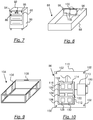
- Fig. 7 shows an embodiment of a locking device 86.
- the locking device 86 is shown in FIG Fig. 7 only one drawer 88 is shown, which is pushed into a cabinet 90.
- the drawer 88 like the RFID key 10, has a symbol 92.
- the cabinet 90 without the locking device 86 is a commercially available cabinet 90 which, in addition to the locking device 86, also has further drawers, compartments or doors.
- the locking device additionally has a trigger 94, for example designed as a button, or a triggering means 94 which can be actuated to transmit or send a locking request to an RFID lock of the locking device 86.
- the locking device 86 also has an output means 95 for outputting a signal.
- the output means 95 is an LED.
- the locking device 86 additionally has or alternatively a loudspeaker, in particular a piezo loudspeaker.
- Fig. 8 shows the locking device 86 from Fig. 7 without the cabinet 90.
- the locking device comprises a drawer 88, an RFID lock 96 and an energy source 98.
- the energy source 98 comprises a battery compartment in which commercially available batteries, such as mignon cells, are accommodated. According to other exemplary embodiments, accumulators or other energy sources 98 are also possible.
- the energy source 98 supplies the RFID lock 96 with energy.
- the locking device 86 is shown from the rear so that the symbol 92 is not visibly arranged behind the RFID lock 96.
- the RFID lock 96 has a bolt 100 on one side.
- This bolt 100 can be operated manually by the user, for example, when a pin is in a release position. If, on the other hand, this pin is in a locked position, the bolt 100 cannot be displaced. The pin can therefore influence the displaceability of the bolt 100, i.e. either release the bolt 100 or also block it.
- the actuation of the pen requires only little electrical energy, while the actuation of the bolt 100 requires a significantly higher expenditure of energy, which however does not have to be provided by the energy source 98, but is provided by the user.
- the RFID lock 96 has a bolt that can be extended and retracted by the RFID lock 96.
- the RFID lock 96 has a servomotor or lifting magnet (not shown), with other drives also being possible in accordance with other exemplary embodiments in order to move the bolt 100. Extending the bolt 100 corresponds to locking and retracting the bolt 100 corresponds to unlocking.
- the RFID lock 96 and the energy source 98 have screw holes 102 which are used to connect the RFID lock 96 and the energy source 98 to the drawer 88.
- the locking device 86 does not have a drawer, in which case the locking device 86, comprising the RFID lock 96 and the energy source 98, can be subsequently integrated in an existing drawer of a cabinet by means of the screw holes 102.
- Fig. 9 shows a cassette 104, which according to an embodiment of the invention
- the locking device 86 is a component part of the locking device 86.
- the cassette 104 is used to subsequently integrate a locking device 86 with a drawer 88 into an existing cabinet 90 without having to make structural changes to the cabinet 90.
- the cassette 104 is pushed into an existing compartment of a cabinet 90, from which a previously accommodated drawer has been removed, and fastened to the cabinet by means of screw holes 106.
- the cassette 104 is from the same view as the drawer 88 in FIG Fig. 8 and has an opening 108 in the form of an elongated hole. If one imagines the cassette 104 with the drawer 88 pushed into it, the opening 108 is adjacent to the bolt 100 of the RFID lock. The locking will not take place upwards, but to the side. When locking with the RFID lock 96, the bolt 100 is moved into the opening 108 and the drawer is thus largely immovable in the cassette 104. In Fig. 9 the bolt 100 extends vertically upwards so that the opening 108 is arranged exactly above the bolt 100. In alternative exemplary embodiments, the lock 96 and the bolt 100 are arranged such that the bolt extends to the side or downwards. In a corresponding manner, the opening 108 is then arranged laterally or on the underside of the drawer 88.
- Fig. 10 shows a schematic representation of the RFID lock 96.
- the RFID lock 96 has a housing 110, shown here open, with screw holes 102.
- a microcontroller 112 is arranged inside the housing, which is connected to an antenna, not shown for the sake of clarity, which is also arranged in the housing 110. Furthermore, the microcontroller 112 is electrically connected to a servomotor 113 or lifting magnet, which is only shown schematically and which can move a bolt 100.
- the microcontroller 112 of the RFID lock 96 has a receiving means 114 and a sending means 116.
- the receiving means 114 and the sending means 116 are arranged in a transmitting and receiving unit 118. According to a further exemplary embodiment, the receiving means 114 and the sending means 116 are combined in a sending and receiving means.
- the transmission means 116 an electromagnetic alternating field, the one to be transmitted Contains, generates.
- An RFID key in particular an RFID transponder unit 10, responds to the received data by modulating the electromagnetic alternating field emitted by the transmission means 116 by the RFID key or the RFID transponder unit 10.
- the modulation of the electromagnetic alternating field is decoded by the receiving means 114 and the response is thus obtained.
- the transmitted data are - as here also above - simply called radio signals.
- the microcontroller also has an identification means 120.
- the identification means 120 is used to identify RFID keys or RFID transponder units 10, which send a radio signal with their unique identifier for their identification.
- the identification means 120 compares the unique identifier with stored or stored unique identifiers. If they match, the identification means 120 reports the RFID key or the RFID transponder unit 10, which has sent the unique identifier, as the identified RFID key or identified RFID transponder unit 10.
- the RFID lock 96 also has a coupling means 122 and a memory 124.
- the coupling means 122 is used to couple to the identified RFID key or the identified RFID transponder unit 10 if the RFID lock 96 has not yet noted any coupling in the memory 124.
- the unique identifier of the RFID key 10 is stored in the memory 124 for recognizing the RFID key 10 and the received period information or the received time information, which is transmitted by the RFID key with a radio signal, is saved.
- the coupling is noted in the memory 124, that is to say stored, so that the RFID lock 96 does not enter into any further coupling with another RFID key 10 as long as the coupling exists.
- the RFID lock 96 has a time control 126.
- the time control 126 has a means for determining a start and / or an end counter value 128 on the basis of a period of the received period information or on the basis of a point in time of the received point in time information, that is to say on the basis of the period or point in time information stored in the memory 124.
- the timing controller 126 also has a counting means 130 for counting. The counting means 130 counts from a predefined or a determined start value to a predefined or a determined end value with a predefined largely constant counting frequency.
- the counting means 130 is therefore started with the start count value.
- the counting means 130 then counts up to an end count value, the start count value and / or the end count value being or are determined on the basis of the point in time or period information stored during the coupling.
- the counting means 130 serves to maintain the coupling until the counting means 130 has reached the final count.
- the final count that is, after the period of the received period information has elapsed or after the point in time of the received time point information has been reached.
- a signal is output by the output means 95.
- the RFID lock 96 releases the coupling to the RFID key or to the RFID transponder unit 10, the coupling being maintained, i.e. noted or stored, until the locking device 86 has expired or after the period of time received has expired Reaching the time of the received time information is unlocked in the case of a locked state.
- the time control 126 serves to enable locking with the locking device only in the event, that is to say to allow it, as long as the coupling is noted. After the period of the received period information has expired or after the point in time of the received point in time information has been reached, that is, after the counting means 130 has reached the final count, locking or locking with the locking device 86 is no longer possible.
- the output means 95 signals that the counting means 130 has reached the final count.
- a locking request is triggered by actuating the trigger 94 as long as the RFID key coupled to the locking device 86 or the RFID transponder unit 10 is brought into the area of the locking device 86.
- “In the area” here describes a distance between the antennas of the locking device 86 and the RFID key or the RFID transponder unit 10 of up to a few centimeters.
- the bolt 100 is extended. The locking device thus executes the locking request that was made with the triggering means 94.
- the trigger or the triggering means 94 can, for example, be mounted in the front area of the drawer 88 and activate the power supply from the energy source 98 to the RFID lock 96 in response to a pressure applied to the trigger 94 by a user.
- the power supply is kept active for a predefined period of time - for example 2 to 4 seconds - so that it can be recognized during this time whether an authorized RFID key or RFID transponder unit 10 is being used.
- the check has different consequences with regard to the opening or closing of the RFID lock 96 RFID key or an RFID transponder unit 10 are locked as long as the RFID key 10 and the RFID lock 96 have not stored any further coupling.
- the position in which the drawer 88 can be locked is preferably defined in such a way that the drawer 88 is pushed into the cabinet 90 as far as it will go. Only in this position does the microcontroller 112 then issue a release for locking.
- the identification means 120 as well as the coupling means 122 and the time control 126 are implemented according to an exemplary embodiment with the microcontroller 112 and software in the microcontroller 112 and are only shown as separate modules for a better overview.
- the transmitting and receiving unit 118 is shown as a component of the microcontroller 112, with a transmitting and receiving unit 118 being implemented according to another exemplary embodiment, which is an electronic component of the RFID lock 96 that is independent of the microcontroller 112 but is electrically connected to the microcontroller 112 and an antenna is equivalent to.
- RFID keys or RFID transponder units 10, locking device 86 and at least one RFID programming device or RFID programming terminal 54 are used in a hospital.
- the locking devices 86 are, for example, installed or integrated subsequently in existing cabinets 90, in particular in bedside cabinets in the patient rooms, and the RFID programming devices 54 are set up in areas of the hospital accessible to patients.
- a patient who wants to protect his valuables from theft during his hospital stay goes to the RFID programming terminal 54 and sets the period there with the input means 56 as a period specification that he will be in the hospital.
- the display 68 shows an amount of money determined by the time recording means, which the patient pays in with the input means 56.
- the RFID programming terminal 54 sends the selected time period to an RFID key 10, which is output by the RFID programming terminal 54.
- the patient selects any free cabinet, the locking device 86 of which is currently not coupled to an RFID key, and holds the RFID key 10 with its symbol 20 in the area of the symbol 92 of the selected locking device 86 Locking device 86 or the RFID lock 96 of the selected locking device 86 and the RFID key or the RFID transponder unit 10 couple.
- the time period that is stored on the RFID key or the RFID transponder unit 10 and was transmitted from the RFID programming terminal 54 to the RFID key or the RFID transponder unit 10 is transferred from the RFID key or the RFID transponder unit 10. of the RFID transponder unit 10 is transmitted to the locking device 86.
- the locking device 86 Upon coupling, the locking device 86 starts a counting means 130 of a time control 126, the counting means 130 counting up to a final count value which is determined by the period of the transmitted period information.
- the patient can now lock and unlock the cabinet 90 with the locking device 86. However, locking is no longer permitted if the final count value has been reached or exceeded by the counting means 130. Unlocking is only possible once after the final count has been reached.
- Fig. 11 shows a schematic representation of a lifting device 140, by means of which electrical energy is converted into a mechanical linear movement of a locking element 142.
- the locking element 142 drives either the, for example, in connection with Fig. 10 illustrated bolt 100 or ensures the locking of the container or the drawer 88 itself.
- the bolt element 142 is driven by means of a lifting drive, preferably designed as a star wheel 144, which in turn is driven by a servomotor, in particular a servomotor.
- the star wheel 144 has a plurality of lever arms 146 which are each provided with one or more holes 148 which serve to receive a connecting pin 150 by means of which such a lever arm 146 with the locking element 142 is connected.
- the plurality of holes 148 and lever arms 146 enable the locking element 142 to be attached flexibly for different installation positions, which is particularly advantageous in the case of different designs of bedside cabinets etc.
- the locking element 142 is guided in a guide tube 152.
- This guide tube 152 has a stop element 154 in order to fasten the guide tube 152 to a wall section of the drawer or the container by means of a nut 156 or another fastening element, such as a tightly fitting rubber stopper.
- an elongated hole 158 is provided on the locking element 142, through which the connecting pin 150 passes and enables this connecting pin 150 to be displaced transversely to the direction of linear movement.
- FIGS. 13a, 13b show alternative embodiments to that in FIG Fig. 11 illustrated lifting device 140.
- this alternative hoist 160 is shown in an initial position.
- the locking element 162 is used to lock the container or the drawer 88 or to drive the in Fig. 10 explained bolt 100.
- a servomotor 164 which with the servomotor 113 from Fig. 10 can be identical, supplies the locking element 162 in addition to energy.
- the electrical energy of the servomotor 164 is converted into a mechanical linear movement of the locking element 162 via a preferably oval-shaped articulated arm 166.
- the oval articulated arm 166 is driven on one side by the servomotor 164 in such a way that it performs a rotary movement.
- the other end of the oval articulated arm 166 strikes a plate-like section 168 of the locking element 162, the locking element 162 being pressed outward, namely through a wall 170.
- the wall 170 can be, for example, the wall of the RFID lock 96 or the wall of the bolt 100.
- a guide shaft (not shown) can be built into the wall 170 in order to ensure that the locking element 162 can slide well in the wall 170.
- a spring 172 which is preferably attached to the outside of the rod-like section 173 of the locking element 162, is preferably arranged between the plate-like section 168 and the wall 170. If the locking element 162, as in Figure 12b shown, in its closed position, namely pressed outwards, the spring 172 is compressed and prevents the locking element 162 from returning to its starting position, as in FIG Figure 12a shown, bounces back.
- the oval articulated arm 166 can advantageously be operated by the servomotor 164 in a position, for example as in FIG Figure 12b shown to be blocked.
- Figures 13a, 13b show an alternative embodiment of the lifting device 160, wherein an oval articulated arm 174 is supplemented by a further articulated arm 176 and these two articulated arms 174, 176 form the articulated arm 166 Figure 12a , 12b substitute.
- the two articulated arms 174, 176 can be dimensioned smaller than the articulated arm 166 from Figure 12a , 12b .
- the locking element 162 In the initial position of the locking element 162, which is shown in Figure 13a As shown, the locking element 162 is in the retracted position with the spring 172 relaxed.
- the servomotor 164 rotates the articulated arm 174 about an axis
- the further articulated arm 176 which is coupled to the articulated arm 174, is also moved and pushes the locking element 162 through the wall 170 outwards ( Figure 13b ).
- the spring 172 compresses it.
- at least the articulated arm 174 can be held in a blocked position by the servomotor 164.
- the drawer By extending the locking element 162 and receiving the locking element 162, e.g. in the opening 108 ( Fig. 9 ), the drawer can thus advantageously be immovable in the cassette 104 ( Fig. 9 ) are locked. Such a design thus provides protection against unauthorized pulling out of the drawer 88.
- a pen can be used to control the slidability of the latch 100.
- 12a , 12b, 13a, 13b The lifting devices 140, 160 shown with the locking elements 162 can also be used to directly control the displaceability of the locking element 100 (then the locking element 162 would be identical to the pin) or to drive the pin.
Landscapes
- Physics & Mathematics (AREA)
- General Physics & Mathematics (AREA)
- Engineering & Computer Science (AREA)
- Computer Networks & Wireless Communication (AREA)
- Lock And Its Accessories (AREA)
Claims (11)
- Système, comprenant au moins une clé RFID, notamment sous la forme d'une unité de transpondeur RFID (10), pour assurer la communication avec au moins un dispositif de verrouillage (86), au moins un dispositif de verrouillage (86) de ce type, pourvu d'une serrure RFID (96), et comprenant au moins un dispositif de programmation RFID (54), lequel est configuré pour programmer de telles clés RFID (10), caractérisé en ce que
la clé RFID est aménagée pour communiquer avec le dispositif de verrouillage (86) pourvu de la serrure RFID (96) et avec le dispositif de programmation RFID (54) et comportea) un moyen d'identification (48), qui est configuré pour identifier au moins une parmi plusieurs serrures RFID (96) prédéfinies et au moins un parmi des dispositifs de programmation RFID (54) prédéfinis, en ce que le moyen d'identification (48) est conçu pour comparer un identifiant univoque envoyé par une serrure RFID (96) ou par un dispositif de programmation RFID (54) avec des identifiants, qui ont été préalablement sauvegardés dans une mémoire (50) de la clé RFID,b) un moyen récepteur (42), destiné à réceptionner un signal radio assorti d'une indication de période ou de moment, le moyen récepteur (42) étant configuré de telle sorte qu'il réceptionne le signal radio assorti d'une indication de période ou de moment de la part du dispositif de programmation RFID (54) identifié par le moyen d'identification (48),c) un moyen de mémorisation (50), destiné à mémoriser l'indication de période ou de moment réceptionnée, le moyen de mémorisation (50) étant configuré de telle sorte que l'indication de période ou de moment du signal radio réceptionné soit mémorisée dans le moyen de mémorisation (50),d) un moyen de couplage (52), destiné à coupler la clé RFID avec la serrure RFID (96) identifiée pour une durée dépendant de la période ou du moment de l'indication de période ou de moment du signal radio réceptionné, le moyen de couplage (52) étant configuré de telle sorte que la clé RFID soit couplée avec la serrure RFID (96) identifiée et que le couplage soit mentionné sur la clé RFID, le moyen de couplage (52) étant conçu de telle sorte que le couplage ne puisse pas être désolidarisé, ou uniquement par la serrure RFID (96) couplée et par l'un des dispositifs de programmation RFID (54) prédéfinis, etque le couplage ne s'effectue que si ni la clé RFID n'est couplée à une autre serrure RFID, ni la serrure RFID identifiée n'est couplée à une autre clé RFID,le couplage incluant l'établissement d'une connexion de la clé RFID avec la serrure RFID (96) identifiée, par mention d'un identifiant (UID) univoque ou d'un autre identifiant inconfusible de la serrure RFID (96) dans la clé RFID ou dans une mémoire de la clé RFID,e) un moyen émetteur (44), destiné à émettre un signal radio assorti de l'indication de période ou de moment mémorisée, le moyen émetteur (44) étant configuré de telle sorte que le signal radio assorti de l'indication de période ou de moment mémorisée soit envoyé à la serrure RFID (96) couplée pendant ou après le couplage avec la serrure RFID (96),et en ce que le dispositif de verrouillage pourvu de la serrure RFID (96) est aménagé pour assurer un accès d'accès ou d'entrée et comportea) un moyen d'identification (120), qui est configuré pour identifier au moins une parmi plusieurs clés RFID prédéfinies, en ce que le moyen d'identification est conçu pour comparer un identifiant univoque envoyé par une clé RFID avec des identifiants qui ont été préalablement sauvegardés dans une mémoire de la serrure RFID,b) un moyen de couplage (122), destiné à coupler la serrure RFID (96) avec la clé RFID identifiée pour une durée dépendant de la période ou du moment d'une indication de période ou de moment d'un signal radio réceptionné et à découpler la serrure RFID (96) de la clé RFID, le moyen de couplage (122) étant configuré de telle sorte, qu'à chaque moment, il ne permette qu'un couplage de la serrure RFID (96) avec une clé RFID,
le couplage incluant l'établissement d'une connexion de la clé RFID identifiée avec la serrure RFID (96) par mention d'un identifiant (UID) univoque ou d'un autre identifiant inconfusible de la serrure RFID (96) dans la clé RFID ou dans une mémoire de la clé RFID,c) un moyen récepteur (114), destiné à réceptionner le signal radio assorti de l'indication de période ou de moment, le moyen récepteur (114) étant configuré de telle sorte qu'il réceptionne le signal radio assorti de l'indication de période ou de moment de la part de la clé RFID identifiée, ledit signal radio étant émis pendant ou une unique fois après le couplage, etd) une commande temporelle (126), qui est configurée de sorte à mentionner le couplage pour une durée dépendant de la période ou du moment de l'indication de période ou de moment du signal radio réceptionné et à ne libérer le verrouillage du dispositif de verrouillage (86) que dans le cas où le couplage est mentionné. - Système selon la revendication 1,
caractérisé en ce que
la clé RFID est structurée de la manière suivante :
un boîtier (12) en silicone, en matière plastique et/ou en papier laminé entoure de manière étanche à l'air et à l'eau des microcontrôleurs (36) et une antenne (38) de la clé RFID, dans la version en silicone, la clé RFID étant conçue sous la forme d'un bracelet (12) que l'on peut mettre et enlever. - Système selon la revendication 1 ou 2,
caractérisé en ce que
sur sa face supérieure, dans la région de l'antenne (38), le bracelet (12) comporte un symbole (20). - Système selon l'une quelconque des revendications précédentes,
caractérisé par les caractéristiques suivantes de la commande temporelle du dispositif de verrouillage :a) un moyen (128), destiné à déterminer une valeur de comptage initiale et/ou finale à l'aide de la période de l'indication de période réceptionnée ou à l'aide du moment de l'indication de moment réceptionnée etb) un moyen de comptage (130), destiné à compter d'une valeur de comptage initiale prédéfinie ou de la valeur de comptage initiale déterminée jusqu'à une valeur de comptage finale prédéfinie ou à la valeur de comptage déterminée, avec une fréquence de comptage prédéfinie, largement constante. - Système selon la revendication 4,
caractérisé en ce que
dans le cas où la serrure RFID (96) est déverrouillée, le moyen de couplage (122) du dispositif de verrouillage (86) est conçu de sorte à annuler le couplage avec la clé RFID couplée lors de l'atteinte et/ou du dépassement de la valeur de comptage finale par le moyen de comptage (130) et de sorte à annuler le couplage avec la clé RFID couplée, dans le cas où la serrure RFID (96) est verrouillée, lors de l'atteinte et/ou du dépassement de la valeur de comptage finale par le moyen de comptage (130) dès que la serrure RFID (96) est déverrouillée. - Système selon l'une quelconque des revendications précédentes,
caractérisé en ce que
le dispositif de verrouillage (86) comporte un moyen déclencheur de verrouillage, destiné à déclencher une demande de verrouillage par actionnement d'un déclencheur (94) du dispositif de verrouillage (86) et/ou après l'écoulement d'une durée prédéfinie en présence d'une clé RFID couplée avec la serrure RFID (96) et/ou par écoulement d'une durée prédéfinie après le retrait d'une clé RFID couplée avec la serrure RFID (96) . - Système selon l'une quelconque des revendications 4 à 6,
caractérisé en ce que
le dispositif de verrouillage (86) comporte un moyen de délivrance (95) destiné à délivrer un signal, notamment un signal acoustique et/ou optique à l'atteinte d'un dépassement de la valeur de comptage finale par le moyen de comptage (130) - Système selon l'une quelconque des revendications précédentes,
caractérisé en ce que
le dispositif de verrouillage (86) comporte au moins une source d'énergie (98), notamment un accumulateur ou une batterie, pour l'alimentation en énergie. - Système selon l'une quelconque des revendications précédentes,
caractérisé en ce que
le dispositif de verrouillage (86) comprend une cassette (104) intégrable dans une armoire (90), dotée d'un tiroir (88) escamotable dans la cassette (104) ou d'un tiroir (88) escamotable dans une armoire (90). - Procédé de verrouillage, destiné à contrôler un accès ou une entrée, caractérisé par les étapes suivantes :a) une étape d'identification, lors de laquelle une clé RFID marquée par la suite et une serrure RFID (96) d'un système de verrouillage marqué par la suite s'identifient réciproquement avec leurs moyens d'identification (48, 120), etb) une étape de couplage, lors de laquelle la clé RFID identifiée et la serrure RFID (96) identifiée se couplent l'une à l'autre avec des moyens de couplage (52, 122), si ni la clé RFID n'est couplée à une autre serrure RFID (96), ni la serrure RFID (96) n'est couplée à une autre clé RFID,c) une étape de réception, lors de laquelle est réceptionné à l'aide d'un moyen récepteur (114) de la serrure RFID (96) un signal radio assorti d'une indication de période ou de moment, qui est envoyé par un moyen émetteur (44) avec la clé RFID identifiée pendant ou une unique fois après le couplage, etd) une étape de commande temporelle, lors de laquelle le couplage est mentionné à l'aide d'une commande temporelle (126) pour une durée dépendant de la période ou du moment de l'indication de période ou de moment réceptionnée et un verrouillage n'est libéré par le dispositif de verrouillage (86) que dans le cas où le couplage est mentionné,la clé RFID communiquant avec le dispositif de verrouillage (86) pourvu de la serrure RFID (96) et avec un dispositif de programmation RFID (54) et comportanta) un moyen d'identification (48), qui est configuré pour identifier au moins une parmi plusieurs serrures RFID (96) prédéfinies et au moins un parmi des dispositifs de programmation RFID (54) prédéfinis, en ce que le moyen d'identification (48) est conçu pour comparer un identifiant univoque envoyé par une serrure RFID (96) ou par un dispositif de programmation RFID (54) avec des identifiants qui ont été préalablement sauvegardés dans une mémoire (50) de la clé RFID,b) un moyen récepteur (42), destiné à réceptionner un signal radio assorti d'une indication de période ou de temps, le moyen récepteur (42) étant configuré de telle sorte qu'il réceptionne le signal radio assorti d'une indication de période ou de moment de la part du dispositif de programmation RFID (54) identifié par le moyen d'identification (48),c) un moyen de mémorisation (50), destiné à mémoriser l'indication de période ou de moment réceptionnée, le moyen de mémorisation (50) étant configuré de telle sorte, que l'indication de période ou de moment du signal radio réceptionné soit mémorisée dans le moyen de mémorisation (50),d) un moyen de couplage (52), destiné à coupler la clé RFID avec la serrure RFID (96) identifiée pour une durée dépendant de la période ou du moment de l'indication de période ou de moment du signal radio réceptionné, le moyen de couplage (52) étant configuré de telle sorte que la clé RFID soit couplée avec la serrure RFID (96) identifiée et que le couplage soit mentionné sur la clé RFID, le moyen de couplage (52) étant conçu de telle sorte que le couplage ne puisse pas être désolidarisé ou uniquement par la serrure RFID (96) couplée et par l'un des dispositifs de programmation RFID (54) prédéfinis, etle couplage n'ayant lieu que si ni la clé RFID n'est couplée à une autre serrure RFID, ni la serrure RFID identifiée n'est couplée à une autre clé RFID,le couplage englobant l'établissement d'une connexion de la clé RFID avec la serrure RFID (96) identifiée par mention d'un identifiant (UID) univoque ou d'un autre identifiant inconfusible de la serrure RFID (96) dans la clé RFID ou dans une mémoire de la clé RFID, ete) un moyen émetteur (44), destiné à émettre un signal radio assorti de l'indication de période ou de moment mémorisée, le moyen émetteur (44) étant configuré de telle sorte, que le signal radio assorti de l'indication de période ou de moment mémorisée soit envoyé à la serrure RFID (96) couplée pendant ou après le couplage avec la serrure RFID (96),et le dispositif de verrouillage procédant avec la serrure RFID (96) à un contrôle d'accès ou d'entrée et comportanta) un moyen d'identification (120), qui est configuré pour identifier au moins une parmi plusieurs clés RFID prédéfinies, en ce que le moyen d'identification est conçu pour comparer un identifiant univoque envoyé par une clé RFID avec des identifiants qui ont été préalablement sauvegardés dans une mémoire de la serrure RFID,b) un moyen de couplage (122), destiné à coupler la serrure RFID (96) avec la clé RFID identifiée pour une durée dépendant de la période ou du moment d'une indication de période ou de moment d'un signal radio réceptionné et à découpler la serrure RFID (96) de la clé RFID, le moyen de couplage (122) étant configuré de telle sorte, qu'à chaque moment, il ne permette qu'un couplage de la serrure RFID (96) avec une clé RFID,
le couplage englobant l'établissement d'une connexion de la clé RFID identifiée avec la serrure RFID (96) par mention d'un identifiant (UID) univoque ou d'un autre identifiant inconfusible de la serrure RFID (96) dans la clé RFID ou dans une mémoire de la clé RFID,c) un moyen récepteur (114), destiné à réceptionner le signal radio assorti de l'indication de période ou de moment, le moyen récepteur (114) étant configuré de telle sorte, qu'il réceptionne le signal radio assorti de l'indication de période ou de moment de la part de la clé RFID identifiée, ledit signal radio étant envoyé pendant ou une unique fois après le couplage, etd) une commande temporelle (126), qui est configurée de sorte à mentionner le couplage pour une durée dépendant de la période ou du moment de l'indication de période ou de moment du signal radio réceptionné et à ne libérer le verrouillage du dispositif de verrouillage (86) que dans le cas où le couplage est mentionné. - Procédé de verrouillage selon la revendication 10, caractérisé par les étapes supplémentaires suivantes :a) une étape lors de laquelle, par un moyen (128), une valeur de comptage initiale et/ou une valeur de comptage finale est déterminée à l'aide de la période de l'indication de période réceptionnée ou à l'aide du moment de l'indication de moment réceptionnée,b) une étape de démarrage de compteur, lors de laquelle l'on fait démarrer un moyen de comptage (130) destiné à compter d'une valeur de comptage initiale prédéfinie ou de la valeur de comptage initiale déterminée jusqu'à une valeur de comptage finale prédéfinie ou à la valeur de comptage finale déterminée, avec une fréquence de comptage largement constante, etc) une étape de demande de verrouillage, lors de laquelle par actionnement d'un déclencheur (94) du dispositif de verrouillage (86) et/ou après écoulement d'un temps prédéfini en présence d'une clé RFID couplée avec la serrure RFID (96) et/ou par écoulement d'un temps prédéfini après le retrait d'une clé RFID couplée avec la serrure RFID (96), une demande de verrouillage est déclenchée.
Applications Claiming Priority (1)
| Application Number | Priority Date | Filing Date | Title |
|---|---|---|---|
| DE202013104312U DE202013104312U1 (de) | 2013-09-20 | 2013-09-20 | RFID-Schlüssel, insbesondere RFID-Transpondereinheit, Programmiervorrichtung und Verriegelungsvorrichtung mit einem RFID-Schloss sowie System daraus |
Publications (2)
| Publication Number | Publication Date |
|---|---|
| EP2851873A1 EP2851873A1 (fr) | 2015-03-25 |
| EP2851873B1 true EP2851873B1 (fr) | 2021-11-17 |
Family
ID=49944384
Family Applications (1)
| Application Number | Title | Priority Date | Filing Date |
|---|---|---|---|
| EP14177319.2A Active EP2851873B1 (fr) | 2013-09-20 | 2014-07-16 | Clé RFID, notamment unité de transpondeur RFID, dispositif et procédé de programmation et dispositif et procédé de verrouillage présentant un verrou RFID et système le composant |
Country Status (3)
| Country | Link |
|---|---|
| EP (1) | EP2851873B1 (fr) |
| DE (1) | DE202013104312U1 (fr) |
| DK (1) | DK2851873T3 (fr) |
Families Citing this family (2)
| Publication number | Priority date | Publication date | Assignee | Title |
|---|---|---|---|---|
| DE102015117041B4 (de) * | 2015-10-07 | 2025-12-04 | Schulte-Schlagbaum Aktiengesellschaft | Elektronische Schließvorrichtung |
| CN111305655B (zh) * | 2020-03-31 | 2024-11-29 | 青岛海容商用冷链股份有限公司 | 一种展示柜智能锁及展示柜 |
Family Cites Families (4)
| Publication number | Priority date | Publication date | Assignee | Title |
|---|---|---|---|---|
| DE50012648D1 (de) * | 2000-02-09 | 2006-06-01 | Scheidt & Bachmann Gmbh | Schliesssystem |
| DE102004052560A1 (de) * | 2004-10-29 | 2006-03-23 | ticos E + S AG | Elektronisches Kartenpfandschloss |
| EP1724731B1 (fr) * | 2005-05-20 | 2008-03-26 | Ojmar S.A. | Système de fermeture électronique programmable |
| DE102006039843A1 (de) * | 2006-08-25 | 2008-02-28 | Fitness Services And Finance Ag | Verriegelungsschloss mit Benutzerauthentifizierung |
-
2013
- 2013-09-20 DE DE202013104312U patent/DE202013104312U1/de not_active Expired - Lifetime
-
2014
- 2014-07-16 EP EP14177319.2A patent/EP2851873B1/fr active Active
- 2014-07-16 DK DK14177319.2T patent/DK2851873T3/da active
Non-Patent Citations (1)
| Title |
|---|
| None * |
Also Published As
| Publication number | Publication date |
|---|---|
| DK2851873T3 (en) | 2022-01-31 |
| EP2851873A1 (fr) | 2015-03-25 |
| DE202013104312U1 (de) | 2013-12-16 |
Similar Documents
| Publication | Publication Date | Title |
|---|---|---|
| EP1327043B1 (fr) | Systeme de fermeture electronique | |
| EP0709534B1 (fr) | Serrure activée par un porteur d'identité | |
| DE19932147A1 (de) | Elektronisches System zur Erfassung und Kontrolle von Patientendaten | |
| DE112016004525T5 (de) | Elektronische Tastatursperre und elektronische Verriegelungssystem für Möbel, Schränke oder Schliessfächer | |
| DE102016112007A1 (de) | Schließanordnung, insbesondere Türschlossanordnung für einen Schaltschrank und ein entsprechendes Verfahren | |
| DE102004013369A1 (de) | Elektronisches Kontroll-System | |
| EP2851873B1 (fr) | Clé RFID, notamment unité de transpondeur RFID, dispositif et procédé de programmation et dispositif et procédé de verrouillage présentant un verrou RFID et système le composant | |
| DE19527801C2 (de) | Schließsystem | |
| DE202012011962U1 (de) | Vorrichtung zum Lagern von Gegenständen | |
| DE19635483C2 (de) | Vorrichtung zur Entnahme und/oder Rückgabe von Gegenständen | |
| DE202015009941U1 (de) | Elektrische Schlossvorrichtung für Möbel und Aufbewahrung | |
| EP3027827B1 (fr) | Poignée de fenêtre, verrouillable de façon électromagnétique | |
| DE202011052080U1 (de) | Vorrichtung zur Aufnahme von Sendungen aller Art | |
| DE102004055979B4 (de) | Verschlusseinheit zur Verwendung an oder in Wertbehältern, Waren- und Dienstleistungsautomaten oder dergleichen | |
| DE19525335A1 (de) | Einrichtung zur Zutrittskontrolle im Gästeeingangsbereich eines Hotels | |
| DE10246642B4 (de) | Elektromechanisches Schloss mit Schutz gegen Manipulation | |
| EP1338735A1 (fr) | Système, installation et procédé de contrôle d'accès | |
| CH700937B1 (de) | Betätigungseinrichtung für Schliessfächer. | |
| DE102022125486A1 (de) | Rücknahmevorrichtung für Datenträger | |
| DE20211468U1 (de) | Sicherheitssystem für Möbel mit mehreren verschließbaren Fächern | |
| DE102006039843A1 (de) | Verriegelungsschloss mit Benutzerauthentifizierung | |
| DE19528250A1 (de) | Verfahren zur Freigabe eines Spintschlosses durch Einführen eines Freigabemediums in den Griff des Spintschlüssels | |
| EP3131068B1 (fr) | Verrou de porte d'armoire en communication sans fil avec une unite centrale | |
| DE202004019169U1 (de) | Elektromechanisches Transponder-Schloss mit Verriegelungselement | |
| DE202008009787U1 (de) | Verriegelungsschloss mit Benutzerauthentifizierung |
Legal Events
| Date | Code | Title | Description |
|---|---|---|---|
| PUAI | Public reference made under article 153(3) epc to a published international application that has entered the european phase |
Free format text: ORIGINAL CODE: 0009012 |
|
| 17P | Request for examination filed |
Effective date: 20140716 |
|
| AK | Designated contracting states |
Kind code of ref document: A1 Designated state(s): AL AT BE BG CH CY CZ DE DK EE ES FI FR GB GR HR HU IE IS IT LI LT LU LV MC MK MT NL NO PL PT RO RS SE SI SK SM TR |
|
| AX | Request for extension of the european patent |
Extension state: BA ME |
|
| R17P | Request for examination filed (corrected) |
Effective date: 20150609 |
|
| RBV | Designated contracting states (corrected) |
Designated state(s): AL AT BE BG CH CY CZ DE DK EE ES FI FR GB GR HR HU IE IS IT LI LT LU LV MC MK MT NL NO PL PT RO RS SE SI SK SM TR |
|
| STAA | Information on the status of an ep patent application or granted ep patent |
Free format text: STATUS: EXAMINATION IS IN PROGRESS |
|
| 17Q | First examination report despatched |
Effective date: 20170227 |
|
| GRAP | Despatch of communication of intention to grant a patent |
Free format text: ORIGINAL CODE: EPIDOSNIGR1 |
|
| STAA | Information on the status of an ep patent application or granted ep patent |
Free format text: STATUS: GRANT OF PATENT IS INTENDED |
|
| INTG | Intention to grant announced |
Effective date: 20210602 |
|
| GRAS | Grant fee paid |
Free format text: ORIGINAL CODE: EPIDOSNIGR3 |
|
| GRAA | (expected) grant |
Free format text: ORIGINAL CODE: 0009210 |
|
| STAA | Information on the status of an ep patent application or granted ep patent |
Free format text: STATUS: THE PATENT HAS BEEN GRANTED |
|
| AK | Designated contracting states |
Kind code of ref document: B1 Designated state(s): AL AT BE BG CH CY CZ DE DK EE ES FI FR GB GR HR HU IE IS IT LI LT LU LV MC MK MT NL NO PL PT RO RS SE SI SK SM TR |
|
| REG | Reference to a national code |
Ref country code: GB Ref legal event code: FG4D Free format text: NOT ENGLISH |
|
| REG | Reference to a national code |
Ref country code: IE Ref legal event code: FG4D Free format text: LANGUAGE OF EP DOCUMENT: GERMAN |
|
| REG | Reference to a national code |
Ref country code: DE Ref legal event code: R096 Ref document number: 502014015989 Country of ref document: DE |
|
| REG | Reference to a national code |
Ref country code: AT Ref legal event code: REF Ref document number: 1448716 Country of ref document: AT Kind code of ref document: T Effective date: 20211215 |
|
| REG | Reference to a national code |
Ref country code: DK Ref legal event code: T3 Effective date: 20220125 |
|
| REG | Reference to a national code |
Ref country code: CH Ref legal event code: PK Free format text: BERICHTIGUNGEN |
|
| REG | Reference to a national code |
Ref country code: NL Ref legal event code: FP |
|
| RAP4 | Party data changed (patent owner data changed or rights of a patent transferred) |
Owner name: HOGENBERG, THERRY GERRIT JAN HORST |
|
| RIN2 | Information on inventor provided after grant (corrected) |
Inventor name: HOGENBERG, THERRY GERRIT JAN HORST |
|
| REG | Reference to a national code |
Ref country code: LT Ref legal event code: MG9D |
|
| PG25 | Lapsed in a contracting state [announced via postgrant information from national office to epo] |
Ref country code: RS Free format text: LAPSE BECAUSE OF FAILURE TO SUBMIT A TRANSLATION OF THE DESCRIPTION OR TO PAY THE FEE WITHIN THE PRESCRIBED TIME-LIMIT Effective date: 20211117 Ref country code: LT Free format text: LAPSE BECAUSE OF FAILURE TO SUBMIT A TRANSLATION OF THE DESCRIPTION OR TO PAY THE FEE WITHIN THE PRESCRIBED TIME-LIMIT Effective date: 20211117 Ref country code: FI Free format text: LAPSE BECAUSE OF FAILURE TO SUBMIT A TRANSLATION OF THE DESCRIPTION OR TO PAY THE FEE WITHIN THE PRESCRIBED TIME-LIMIT Effective date: 20211117 Ref country code: BG Free format text: LAPSE BECAUSE OF FAILURE TO SUBMIT A TRANSLATION OF THE DESCRIPTION OR TO PAY THE FEE WITHIN THE PRESCRIBED TIME-LIMIT Effective date: 20220217 |
|
| PG25 | Lapsed in a contracting state [announced via postgrant information from national office to epo] |
Ref country code: IS Free format text: LAPSE BECAUSE OF FAILURE TO SUBMIT A TRANSLATION OF THE DESCRIPTION OR TO PAY THE FEE WITHIN THE PRESCRIBED TIME-LIMIT Effective date: 20220317 Ref country code: SE Free format text: LAPSE BECAUSE OF FAILURE TO SUBMIT A TRANSLATION OF THE DESCRIPTION OR TO PAY THE FEE WITHIN THE PRESCRIBED TIME-LIMIT Effective date: 20211117 Ref country code: PT Free format text: LAPSE BECAUSE OF FAILURE TO SUBMIT A TRANSLATION OF THE DESCRIPTION OR TO PAY THE FEE WITHIN THE PRESCRIBED TIME-LIMIT Effective date: 20220317 Ref country code: PL Free format text: LAPSE BECAUSE OF FAILURE TO SUBMIT A TRANSLATION OF THE DESCRIPTION OR TO PAY THE FEE WITHIN THE PRESCRIBED TIME-LIMIT Effective date: 20211117 Ref country code: NO Free format text: LAPSE BECAUSE OF FAILURE TO SUBMIT A TRANSLATION OF THE DESCRIPTION OR TO PAY THE FEE WITHIN THE PRESCRIBED TIME-LIMIT Effective date: 20220217 Ref country code: LV Free format text: LAPSE BECAUSE OF FAILURE TO SUBMIT A TRANSLATION OF THE DESCRIPTION OR TO PAY THE FEE WITHIN THE PRESCRIBED TIME-LIMIT Effective date: 20211117 Ref country code: HR Free format text: LAPSE BECAUSE OF FAILURE TO SUBMIT A TRANSLATION OF THE DESCRIPTION OR TO PAY THE FEE WITHIN THE PRESCRIBED TIME-LIMIT Effective date: 20211117 Ref country code: GR Free format text: LAPSE BECAUSE OF FAILURE TO SUBMIT A TRANSLATION OF THE DESCRIPTION OR TO PAY THE FEE WITHIN THE PRESCRIBED TIME-LIMIT Effective date: 20220218 Ref country code: ES Free format text: LAPSE BECAUSE OF FAILURE TO SUBMIT A TRANSLATION OF THE DESCRIPTION OR TO PAY THE FEE WITHIN THE PRESCRIBED TIME-LIMIT Effective date: 20211117 |
|
| PG25 | Lapsed in a contracting state [announced via postgrant information from national office to epo] |
Ref country code: SM Free format text: LAPSE BECAUSE OF FAILURE TO SUBMIT A TRANSLATION OF THE DESCRIPTION OR TO PAY THE FEE WITHIN THE PRESCRIBED TIME-LIMIT Effective date: 20211117 Ref country code: SK Free format text: LAPSE BECAUSE OF FAILURE TO SUBMIT A TRANSLATION OF THE DESCRIPTION OR TO PAY THE FEE WITHIN THE PRESCRIBED TIME-LIMIT Effective date: 20211117 Ref country code: RO Free format text: LAPSE BECAUSE OF FAILURE TO SUBMIT A TRANSLATION OF THE DESCRIPTION OR TO PAY THE FEE WITHIN THE PRESCRIBED TIME-LIMIT Effective date: 20211117 Ref country code: EE Free format text: LAPSE BECAUSE OF FAILURE TO SUBMIT A TRANSLATION OF THE DESCRIPTION OR TO PAY THE FEE WITHIN THE PRESCRIBED TIME-LIMIT Effective date: 20211117 Ref country code: CZ Free format text: LAPSE BECAUSE OF FAILURE TO SUBMIT A TRANSLATION OF THE DESCRIPTION OR TO PAY THE FEE WITHIN THE PRESCRIBED TIME-LIMIT Effective date: 20211117 |
|
| REG | Reference to a national code |
Ref country code: DE Ref legal event code: R097 Ref document number: 502014015989 Country of ref document: DE |
|
| PLBE | No opposition filed within time limit |
Free format text: ORIGINAL CODE: 0009261 |
|
| STAA | Information on the status of an ep patent application or granted ep patent |
Free format text: STATUS: NO OPPOSITION FILED WITHIN TIME LIMIT |
|
| 26N | No opposition filed |
Effective date: 20220818 |
|
| PG25 | Lapsed in a contracting state [announced via postgrant information from national office to epo] |
Ref country code: AL Free format text: LAPSE BECAUSE OF FAILURE TO SUBMIT A TRANSLATION OF THE DESCRIPTION OR TO PAY THE FEE WITHIN THE PRESCRIBED TIME-LIMIT Effective date: 20211117 |
|
| PG25 | Lapsed in a contracting state [announced via postgrant information from national office to epo] |
Ref country code: SI Free format text: LAPSE BECAUSE OF FAILURE TO SUBMIT A TRANSLATION OF THE DESCRIPTION OR TO PAY THE FEE WITHIN THE PRESCRIBED TIME-LIMIT Effective date: 20211117 |
|
| PG25 | Lapsed in a contracting state [announced via postgrant information from national office to epo] |
Ref country code: MC Free format text: LAPSE BECAUSE OF FAILURE TO SUBMIT A TRANSLATION OF THE DESCRIPTION OR TO PAY THE FEE WITHIN THE PRESCRIBED TIME-LIMIT Effective date: 20211117 |
|
| PG25 | Lapsed in a contracting state [announced via postgrant information from national office to epo] |
Ref country code: IT Free format text: LAPSE BECAUSE OF FAILURE TO SUBMIT A TRANSLATION OF THE DESCRIPTION OR TO PAY THE FEE WITHIN THE PRESCRIBED TIME-LIMIT Effective date: 20211117 |
|
| P01 | Opt-out of the competence of the unified patent court (upc) registered |
Effective date: 20230516 |
|
| PG25 | Lapsed in a contracting state [announced via postgrant information from national office to epo] |
Ref country code: IE Free format text: LAPSE BECAUSE OF NON-PAYMENT OF DUE FEES Effective date: 20220716 |
|
| PG25 | Lapsed in a contracting state [announced via postgrant information from national office to epo] |
Ref country code: HU Free format text: LAPSE BECAUSE OF FAILURE TO SUBMIT A TRANSLATION OF THE DESCRIPTION OR TO PAY THE FEE WITHIN THE PRESCRIBED TIME-LIMIT; INVALID AB INITIO Effective date: 20140716 |
|
| PG25 | Lapsed in a contracting state [announced via postgrant information from national office to epo] |
Ref country code: MK Free format text: LAPSE BECAUSE OF FAILURE TO SUBMIT A TRANSLATION OF THE DESCRIPTION OR TO PAY THE FEE WITHIN THE PRESCRIBED TIME-LIMIT Effective date: 20211117 Ref country code: CY Free format text: LAPSE BECAUSE OF FAILURE TO SUBMIT A TRANSLATION OF THE DESCRIPTION OR TO PAY THE FEE WITHIN THE PRESCRIBED TIME-LIMIT Effective date: 20211117 |
|
| PG25 | Lapsed in a contracting state [announced via postgrant information from national office to epo] |
Ref country code: TR Free format text: LAPSE BECAUSE OF FAILURE TO SUBMIT A TRANSLATION OF THE DESCRIPTION OR TO PAY THE FEE WITHIN THE PRESCRIBED TIME-LIMIT Effective date: 20211117 |
|
| PGFP | Annual fee paid to national office [announced via postgrant information from national office to epo] |
Ref country code: LU Payment date: 20240722 Year of fee payment: 11 |
|
| PG25 | Lapsed in a contracting state [announced via postgrant information from national office to epo] |
Ref country code: MT Free format text: LAPSE BECAUSE OF FAILURE TO SUBMIT A TRANSLATION OF THE DESCRIPTION OR TO PAY THE FEE WITHIN THE PRESCRIBED TIME-LIMIT Effective date: 20211117 |
|
| PGFP | Annual fee paid to national office [announced via postgrant information from national office to epo] |
Ref country code: DK Payment date: 20240722 Year of fee payment: 11 |
|
| PGFP | Annual fee paid to national office [announced via postgrant information from national office to epo] |
Ref country code: BE Payment date: 20240722 Year of fee payment: 11 |
|
| PGFP | Annual fee paid to national office [announced via postgrant information from national office to epo] |
Ref country code: CH Payment date: 20240801 Year of fee payment: 11 |
|
| PGFP | Annual fee paid to national office [announced via postgrant information from national office to epo] |
Ref country code: AT Payment date: 20240718 Year of fee payment: 11 |
|
| PGFP | Annual fee paid to national office [announced via postgrant information from national office to epo] |
Ref country code: NL Payment date: 20250723 Year of fee payment: 12 |
|
| PGFP | Annual fee paid to national office [announced via postgrant information from national office to epo] |
Ref country code: DE Payment date: 20250627 Year of fee payment: 12 |
|
| PGFP | Annual fee paid to national office [announced via postgrant information from national office to epo] |
Ref country code: GB Payment date: 20250724 Year of fee payment: 12 |
|
| PGFP | Annual fee paid to national office [announced via postgrant information from national office to epo] |
Ref country code: FR Payment date: 20250723 Year of fee payment: 12 |
|
| REG | Reference to a national code |
Ref country code: DK Ref legal event code: EBP Effective date: 20250731 |
|
| REG | Reference to a national code |
Ref country code: CH Ref legal event code: H13 Free format text: ST27 STATUS EVENT CODE: U-0-0-H10-H13 (AS PROVIDED BY THE NATIONAL OFFICE) Effective date: 20260224 |
|
| REG | Reference to a national code |
Ref country code: AT Ref legal event code: MM01 Ref document number: 1448716 Country of ref document: AT Kind code of ref document: T Effective date: 20250716 |
|
| PG25 | Lapsed in a contracting state [announced via postgrant information from national office to epo] |
Ref country code: LU Free format text: LAPSE BECAUSE OF NON-PAYMENT OF DUE FEES Effective date: 20250716 |
|
| REG | Reference to a national code |
Ref country code: BE Ref legal event code: MM Effective date: 20250731 |
|
| PG25 | Lapsed in a contracting state [announced via postgrant information from national office to epo] |
Ref country code: AT Free format text: LAPSE BECAUSE OF NON-PAYMENT OF DUE FEES Effective date: 20250716 |
|
| PG25 | Lapsed in a contracting state [announced via postgrant information from national office to epo] |
Ref country code: BE Free format text: LAPSE BECAUSE OF NON-PAYMENT OF DUE FEES Effective date: 20250731 |
|
| PG25 | Lapsed in a contracting state [announced via postgrant information from national office to epo] |
Ref country code: CH Free format text: LAPSE BECAUSE OF NON-PAYMENT OF DUE FEES Effective date: 20250731 |