EP2851973A1 - Dispositif de décharge d'énergie de batterie - Google Patents
Dispositif de décharge d'énergie de batterie Download PDFInfo
- Publication number
- EP2851973A1 EP2851973A1 EP20130791664 EP13791664A EP2851973A1 EP 2851973 A1 EP2851973 A1 EP 2851973A1 EP 20130791664 EP20130791664 EP 20130791664 EP 13791664 A EP13791664 A EP 13791664A EP 2851973 A1 EP2851973 A1 EP 2851973A1
- Authority
- EP
- European Patent Office
- Prior art keywords
- battery
- water
- battery pack
- electrolyte
- electrolyte substance
- Prior art date
- Legal status (The legal status is an assumption and is not a legal conclusion. Google has not performed a legal analysis and makes no representation as to the accuracy of the status listed.)
- Withdrawn
Links
Images


Classifications
-
- B—PERFORMING OPERATIONS; TRANSPORTING
- B60—VEHICLES IN GENERAL
- B60K—ARRANGEMENT OR MOUNTING OF PROPULSION UNITS OR OF TRANSMISSIONS IN VEHICLES; ARRANGEMENT OR MOUNTING OF PLURAL DIVERSE PRIME-MOVERS IN VEHICLES; AUXILIARY DRIVES FOR VEHICLES; INSTRUMENTATION OR DASHBOARDS FOR VEHICLES; ARRANGEMENTS IN CONNECTION WITH COOLING, AIR INTAKE, GAS EXHAUST OR FUEL SUPPLY OF PROPULSION UNITS IN VEHICLES
- B60K6/00—Arrangement or mounting of plural diverse prime-movers for mutual or common propulsion, e.g. hybrid propulsion systems comprising electric motors and internal combustion engines
- B60K6/20—Arrangement or mounting of plural diverse prime-movers for mutual or common propulsion, e.g. hybrid propulsion systems comprising electric motors and internal combustion engines the prime-movers consisting of electric motors and internal combustion engines, e.g. HEVs
- B60K6/22—Arrangement or mounting of plural diverse prime-movers for mutual or common propulsion, e.g. hybrid propulsion systems comprising electric motors and internal combustion engines the prime-movers consisting of electric motors and internal combustion engines, e.g. HEVs characterised by apparatus, components or means specially adapted for HEVs
- B60K6/28—Arrangement or mounting of plural diverse prime-movers for mutual or common propulsion, e.g. hybrid propulsion systems comprising electric motors and internal combustion engines the prime-movers consisting of electric motors and internal combustion engines, e.g. HEVs characterised by apparatus, components or means specially adapted for HEVs characterised by the electric energy storing means, e.g. batteries or capacitors
-
- B—PERFORMING OPERATIONS; TRANSPORTING
- B60—VEHICLES IN GENERAL
- B60L—PROPULSION OF ELECTRICALLY-PROPELLED VEHICLES; SUPPLYING ELECTRIC POWER FOR AUXILIARY EQUIPMENT OF ELECTRICALLY-PROPELLED VEHICLES; ELECTRODYNAMIC BRAKE SYSTEMS FOR VEHICLES IN GENERAL; MAGNETIC SUSPENSION OR LEVITATION FOR VEHICLES; MONITORING OPERATING VARIABLES OF ELECTRICALLY-PROPELLED VEHICLES; ELECTRIC SAFETY DEVICES FOR ELECTRICALLY-PROPELLED VEHICLES
- B60L3/00—Electric devices on electrically-propelled vehicles for safety purposes; Monitoring operating variables, e.g. speed, deceleration or energy consumption
- B60L3/0023—Detecting, eliminating, remedying or compensating for drive train abnormalities, e.g. failures within the drive train
- B60L3/0046—Detecting, eliminating, remedying or compensating for drive train abnormalities, e.g. failures within the drive train relating to electric energy storage systems, e.g. batteries or capacitors
-
- B—PERFORMING OPERATIONS; TRANSPORTING
- B60—VEHICLES IN GENERAL
- B60L—PROPULSION OF ELECTRICALLY-PROPELLED VEHICLES; SUPPLYING ELECTRIC POWER FOR AUXILIARY EQUIPMENT OF ELECTRICALLY-PROPELLED VEHICLES; ELECTRODYNAMIC BRAKE SYSTEMS FOR VEHICLES IN GENERAL; MAGNETIC SUSPENSION OR LEVITATION FOR VEHICLES; MONITORING OPERATING VARIABLES OF ELECTRICALLY-PROPELLED VEHICLES; ELECTRIC SAFETY DEVICES FOR ELECTRICALLY-PROPELLED VEHICLES
- B60L3/00—Electric devices on electrically-propelled vehicles for safety purposes; Monitoring operating variables, e.g. speed, deceleration or energy consumption
- B60L3/0023—Detecting, eliminating, remedying or compensating for drive train abnormalities, e.g. failures within the drive train
- B60L3/0069—Detecting, eliminating, remedying or compensating for drive train abnormalities, e.g. failures within the drive train relating to the isolation, e.g. ground fault or leak current
-
- B—PERFORMING OPERATIONS; TRANSPORTING
- B60—VEHICLES IN GENERAL
- B60L—PROPULSION OF ELECTRICALLY-PROPELLED VEHICLES; SUPPLYING ELECTRIC POWER FOR AUXILIARY EQUIPMENT OF ELECTRICALLY-PROPELLED VEHICLES; ELECTRODYNAMIC BRAKE SYSTEMS FOR VEHICLES IN GENERAL; MAGNETIC SUSPENSION OR LEVITATION FOR VEHICLES; MONITORING OPERATING VARIABLES OF ELECTRICALLY-PROPELLED VEHICLES; ELECTRIC SAFETY DEVICES FOR ELECTRICALLY-PROPELLED VEHICLES
- B60L3/00—Electric devices on electrically-propelled vehicles for safety purposes; Monitoring operating variables, e.g. speed, deceleration or energy consumption
- B60L3/04—Cutting off the power supply under fault conditions
-
- B—PERFORMING OPERATIONS; TRANSPORTING
- B60—VEHICLES IN GENERAL
- B60L—PROPULSION OF ELECTRICALLY-PROPELLED VEHICLES; SUPPLYING ELECTRIC POWER FOR AUXILIARY EQUIPMENT OF ELECTRICALLY-PROPELLED VEHICLES; ELECTRODYNAMIC BRAKE SYSTEMS FOR VEHICLES IN GENERAL; MAGNETIC SUSPENSION OR LEVITATION FOR VEHICLES; MONITORING OPERATING VARIABLES OF ELECTRICALLY-PROPELLED VEHICLES; ELECTRIC SAFETY DEVICES FOR ELECTRICALLY-PROPELLED VEHICLES
- B60L50/00—Electric propulsion with power supplied within the vehicle
- B60L50/50—Electric propulsion with power supplied within the vehicle using propulsion power supplied by batteries or fuel cells
- B60L50/60—Electric propulsion with power supplied within the vehicle using propulsion power supplied by batteries or fuel cells using power supplied by batteries
- B60L50/64—Constructional details of batteries specially adapted for electric vehicles
-
- B—PERFORMING OPERATIONS; TRANSPORTING
- B60—VEHICLES IN GENERAL
- B60L—PROPULSION OF ELECTRICALLY-PROPELLED VEHICLES; SUPPLYING ELECTRIC POWER FOR AUXILIARY EQUIPMENT OF ELECTRICALLY-PROPELLED VEHICLES; ELECTRODYNAMIC BRAKE SYSTEMS FOR VEHICLES IN GENERAL; MAGNETIC SUSPENSION OR LEVITATION FOR VEHICLES; MONITORING OPERATING VARIABLES OF ELECTRICALLY-PROPELLED VEHICLES; ELECTRIC SAFETY DEVICES FOR ELECTRICALLY-PROPELLED VEHICLES
- B60L50/00—Electric propulsion with power supplied within the vehicle
- B60L50/50—Electric propulsion with power supplied within the vehicle using propulsion power supplied by batteries or fuel cells
- B60L50/60—Electric propulsion with power supplied within the vehicle using propulsion power supplied by batteries or fuel cells using power supplied by batteries
- B60L50/66—Arrangements of batteries
-
- B—PERFORMING OPERATIONS; TRANSPORTING
- B60—VEHICLES IN GENERAL
- B60L—PROPULSION OF ELECTRICALLY-PROPELLED VEHICLES; SUPPLYING ELECTRIC POWER FOR AUXILIARY EQUIPMENT OF ELECTRICALLY-PROPELLED VEHICLES; ELECTRODYNAMIC BRAKE SYSTEMS FOR VEHICLES IN GENERAL; MAGNETIC SUSPENSION OR LEVITATION FOR VEHICLES; MONITORING OPERATING VARIABLES OF ELECTRICALLY-PROPELLED VEHICLES; ELECTRIC SAFETY DEVICES FOR ELECTRICALLY-PROPELLED VEHICLES
- B60L58/00—Methods or circuit arrangements for monitoring or controlling batteries or fuel cells, specially adapted for electric vehicles
- B60L58/10—Methods or circuit arrangements for monitoring or controlling batteries or fuel cells, specially adapted for electric vehicles for monitoring or controlling batteries
- B60L58/18—Methods or circuit arrangements for monitoring or controlling batteries or fuel cells, specially adapted for electric vehicles for monitoring or controlling batteries of two or more battery modules
- B60L58/21—Methods or circuit arrangements for monitoring or controlling batteries or fuel cells, specially adapted for electric vehicles for monitoring or controlling batteries of two or more battery modules having the same nominal voltage
-
- H—ELECTRICITY
- H01—ELECTRIC ELEMENTS
- H01M—PROCESSES OR MEANS, e.g. BATTERIES, FOR THE DIRECT CONVERSION OF CHEMICAL ENERGY INTO ELECTRICAL ENERGY
- H01M10/00—Secondary cells; Manufacture thereof
- H01M10/42—Methods or arrangements for servicing or maintenance of secondary cells or secondary half-cells
- H01M10/44—Methods for charging or discharging
-
- H—ELECTRICITY
- H01—ELECTRIC ELEMENTS
- H01M—PROCESSES OR MEANS, e.g. BATTERIES, FOR THE DIRECT CONVERSION OF CHEMICAL ENERGY INTO ELECTRICAL ENERGY
- H01M10/00—Secondary cells; Manufacture thereof
- H01M10/60—Heating or cooling; Temperature control
- H01M10/61—Types of temperature control
- H01M10/613—Cooling or keeping cold
-
- H—ELECTRICITY
- H01—ELECTRIC ELEMENTS
- H01M—PROCESSES OR MEANS, e.g. BATTERIES, FOR THE DIRECT CONVERSION OF CHEMICAL ENERGY INTO ELECTRICAL ENERGY
- H01M10/00—Secondary cells; Manufacture thereof
- H01M10/60—Heating or cooling; Temperature control
- H01M10/62—Heating or cooling; Temperature control specially adapted for specific applications
- H01M10/625—Vehicles
-
- H—ELECTRICITY
- H01—ELECTRIC ELEMENTS
- H01M—PROCESSES OR MEANS, e.g. BATTERIES, FOR THE DIRECT CONVERSION OF CHEMICAL ENERGY INTO ELECTRICAL ENERGY
- H01M10/00—Secondary cells; Manufacture thereof
- H01M10/60—Heating or cooling; Temperature control
- H01M10/65—Means for temperature control structurally associated with the cells
- H01M10/655—Solid structures for heat exchange or heat conduction
- H01M10/6556—Solid parts with flow channel passages or pipes for heat exchange
-
- H—ELECTRICITY
- H01—ELECTRIC ELEMENTS
- H01M—PROCESSES OR MEANS, e.g. BATTERIES, FOR THE DIRECT CONVERSION OF CHEMICAL ENERGY INTO ELECTRICAL ENERGY
- H01M10/00—Secondary cells; Manufacture thereof
- H01M10/60—Heating or cooling; Temperature control
- H01M10/65—Means for temperature control structurally associated with the cells
- H01M10/656—Means for temperature control structurally associated with the cells characterised by the type of heat-exchange fluid
- H01M10/6567—Liquids
-
- H—ELECTRICITY
- H01—ELECTRIC ELEMENTS
- H01M—PROCESSES OR MEANS, e.g. BATTERIES, FOR THE DIRECT CONVERSION OF CHEMICAL ENERGY INTO ELECTRICAL ENERGY
- H01M50/00—Constructional details or processes of manufacture of the non-active parts of electrochemical cells other than fuel cells, e.g. hybrid cells
- H01M50/20—Mountings; Secondary casings or frames; Racks, modules or packs; Suspension devices; Shock absorbers; Transport or carrying devices; Holders
- H01M50/204—Racks, modules or packs for multiple batteries or multiple cells
-
- H—ELECTRICITY
- H01—ELECTRIC ELEMENTS
- H01M—PROCESSES OR MEANS, e.g. BATTERIES, FOR THE DIRECT CONVERSION OF CHEMICAL ENERGY INTO ELECTRICAL ENERGY
- H01M50/00—Constructional details or processes of manufacture of the non-active parts of electrochemical cells other than fuel cells, e.g. hybrid cells
- H01M50/20—Mountings; Secondary casings or frames; Racks, modules or packs; Suspension devices; Shock absorbers; Transport or carrying devices; Holders
- H01M50/249—Mountings; Secondary casings or frames; Racks, modules or packs; Suspension devices; Shock absorbers; Transport or carrying devices; Holders specially adapted for aircraft or vehicles, e.g. cars or trains
-
- H—ELECTRICITY
- H01—ELECTRIC ELEMENTS
- H01M—PROCESSES OR MEANS, e.g. BATTERIES, FOR THE DIRECT CONVERSION OF CHEMICAL ENERGY INTO ELECTRICAL ENERGY
- H01M50/00—Constructional details or processes of manufacture of the non-active parts of electrochemical cells other than fuel cells, e.g. hybrid cells
- H01M50/60—Arrangements or processes for filling or topping-up with liquids; Arrangements or processes for draining liquids from casings
- H01M50/609—Arrangements or processes for filling with liquid, e.g. electrolytes
- H01M50/627—Filling ports
-
- B—PERFORMING OPERATIONS; TRANSPORTING
- B60—VEHICLES IN GENERAL
- B60K—ARRANGEMENT OR MOUNTING OF PROPULSION UNITS OR OF TRANSMISSIONS IN VEHICLES; ARRANGEMENT OR MOUNTING OF PLURAL DIVERSE PRIME-MOVERS IN VEHICLES; AUXILIARY DRIVES FOR VEHICLES; INSTRUMENTATION OR DASHBOARDS FOR VEHICLES; ARRANGEMENTS IN CONNECTION WITH COOLING, AIR INTAKE, GAS EXHAUST OR FUEL SUPPLY OF PROPULSION UNITS IN VEHICLES
- B60K1/00—Arrangement or mounting of electrical propulsion units
- B60K2001/003—Arrangement or mounting of electrical propulsion units with means for cooling the electrical propulsion units
- B60K2001/005—Arrangement or mounting of electrical propulsion units with means for cooling the electrical propulsion units the electric storage means
-
- B—PERFORMING OPERATIONS; TRANSPORTING
- B60—VEHICLES IN GENERAL
- B60K—ARRANGEMENT OR MOUNTING OF PROPULSION UNITS OR OF TRANSMISSIONS IN VEHICLES; ARRANGEMENT OR MOUNTING OF PLURAL DIVERSE PRIME-MOVERS IN VEHICLES; AUXILIARY DRIVES FOR VEHICLES; INSTRUMENTATION OR DASHBOARDS FOR VEHICLES; ARRANGEMENTS IN CONNECTION WITH COOLING, AIR INTAKE, GAS EXHAUST OR FUEL SUPPLY OF PROPULSION UNITS IN VEHICLES
- B60K1/00—Arrangement or mounting of electrical propulsion units
- B60K1/04—Arrangement or mounting of electrical propulsion units of the electric storage means for propulsion
- B60K2001/0405—Arrangement or mounting of electrical propulsion units of the electric storage means for propulsion characterised by their position
- B60K2001/0422—Arrangement under the front seats
-
- B—PERFORMING OPERATIONS; TRANSPORTING
- B60—VEHICLES IN GENERAL
- B60L—PROPULSION OF ELECTRICALLY-PROPELLED VEHICLES; SUPPLYING ELECTRIC POWER FOR AUXILIARY EQUIPMENT OF ELECTRICALLY-PROPELLED VEHICLES; ELECTRODYNAMIC BRAKE SYSTEMS FOR VEHICLES IN GENERAL; MAGNETIC SUSPENSION OR LEVITATION FOR VEHICLES; MONITORING OPERATING VARIABLES OF ELECTRICALLY-PROPELLED VEHICLES; ELECTRIC SAFETY DEVICES FOR ELECTRICALLY-PROPELLED VEHICLES
- B60L2240/00—Control parameters of input or output; Target parameters
- B60L2240/40—Drive Train control parameters
- B60L2240/54—Drive Train control parameters related to batteries
- B60L2240/545—Temperature
-
- B—PERFORMING OPERATIONS; TRANSPORTING
- B60—VEHICLES IN GENERAL
- B60L—PROPULSION OF ELECTRICALLY-PROPELLED VEHICLES; SUPPLYING ELECTRIC POWER FOR AUXILIARY EQUIPMENT OF ELECTRICALLY-PROPELLED VEHICLES; ELECTRODYNAMIC BRAKE SYSTEMS FOR VEHICLES IN GENERAL; MAGNETIC SUSPENSION OR LEVITATION FOR VEHICLES; MONITORING OPERATING VARIABLES OF ELECTRICALLY-PROPELLED VEHICLES; ELECTRIC SAFETY DEVICES FOR ELECTRICALLY-PROPELLED VEHICLES
- B60L58/00—Methods or circuit arrangements for monitoring or controlling batteries or fuel cells, specially adapted for electric vehicles
- B60L58/10—Methods or circuit arrangements for monitoring or controlling batteries or fuel cells, specially adapted for electric vehicles for monitoring or controlling batteries
- B60L58/24—Methods or circuit arrangements for monitoring or controlling batteries or fuel cells, specially adapted for electric vehicles for monitoring or controlling batteries for controlling the temperature of batteries
- B60L58/26—Methods or circuit arrangements for monitoring or controlling batteries or fuel cells, specially adapted for electric vehicles for monitoring or controlling batteries for controlling the temperature of batteries by cooling
-
- H—ELECTRICITY
- H01—ELECTRIC ELEMENTS
- H01M—PROCESSES OR MEANS, e.g. BATTERIES, FOR THE DIRECT CONVERSION OF CHEMICAL ENERGY INTO ELECTRICAL ENERGY
- H01M2200/00—Safety devices for primary or secondary batteries
-
- H—ELECTRICITY
- H01—ELECTRIC ELEMENTS
- H01M—PROCESSES OR MEANS, e.g. BATTERIES, FOR THE DIRECT CONVERSION OF CHEMICAL ENERGY INTO ELECTRICAL ENERGY
- H01M2220/00—Batteries for particular applications
- H01M2220/20—Batteries in motive systems, e.g. vehicle, ship, plane
-
- Y—GENERAL TAGGING OF NEW TECHNOLOGICAL DEVELOPMENTS; GENERAL TAGGING OF CROSS-SECTIONAL TECHNOLOGIES SPANNING OVER SEVERAL SECTIONS OF THE IPC; TECHNICAL SUBJECTS COVERED BY FORMER USPC CROSS-REFERENCE ART COLLECTIONS [XRACs] AND DIGESTS
- Y02—TECHNOLOGIES OR APPLICATIONS FOR MITIGATION OR ADAPTATION AGAINST CLIMATE CHANGE
- Y02E—REDUCTION OF GREENHOUSE GAS [GHG] EMISSIONS, RELATED TO ENERGY GENERATION, TRANSMISSION OR DISTRIBUTION
- Y02E60/00—Enabling technologies; Technologies with a potential or indirect contribution to GHG emissions mitigation
- Y02E60/10—Energy storage using batteries
-
- Y—GENERAL TAGGING OF NEW TECHNOLOGICAL DEVELOPMENTS; GENERAL TAGGING OF CROSS-SECTIONAL TECHNOLOGIES SPANNING OVER SEVERAL SECTIONS OF THE IPC; TECHNICAL SUBJECTS COVERED BY FORMER USPC CROSS-REFERENCE ART COLLECTIONS [XRACs] AND DIGESTS
- Y02—TECHNOLOGIES OR APPLICATIONS FOR MITIGATION OR ADAPTATION AGAINST CLIMATE CHANGE
- Y02T—CLIMATE CHANGE MITIGATION TECHNOLOGIES RELATED TO TRANSPORTATION
- Y02T10/00—Road transport of goods or passengers
- Y02T10/60—Other road transportation technologies with climate change mitigation effect
- Y02T10/70—Energy storage systems for electromobility, e.g. batteries
Definitions
- the present invention relates to a battery energy discharge device mounted in a vehicle, and more particularly, to a battery energy discharge device for discharging the electric energy of a drive battery accommodated inside a battery pack mounted in a vehicle.
- electric-type vehicles such as electric vehicles (hereafter referred to as EV) that travel using a motor serving as a drive source, plug-in hybrid vehicles (hereafter referred to as PHV) or vehicles that travel using, for example a motor driven by a fuel cell, a motor serving as a drive source and an inverter (electric power control apparatus) are accommodated on the side of a drive source accommodating compartment, a drive battery is disposed on the lower side of the passenger compartment, the two are connected using high-voltage cables so that electric power can be transferred therebetween.
- the drive battery is usually accommodated inside a battery pack serving as a housing, and is supported by the lower section of the floor of the passenger compartment.
- an electric vehicle such as an EV or PHV, equipped with such a drive battery caused an accident or the like and the vehicle body is damaged and the vehicle fell into an emergency
- rescue and recovery activities for the vehicle are carried out, and the connection between the high-voltage electric power source circuit and the battery of the battery pack in the disabled vehicle is disconnected according to the degree of the damage, thereby preventing electric shock, firing, etc.
- a through-hole is opened by opening the through-hole service plug lid provided in the floor of the vehicle body, a service plug is extracted through this through-hole from a switch capable of switching the power source circuit provided inside the battery pack, thereby disconnecting the connection between the high-voltage electric power source circuit and the battery.
- a worker wearing insulating protective equipment fills the inside of the battery pack with water through the through-hole or a duct of an air conditioner for cooling, whereby the battery is discharged for several hours, the electric energy stored in the battery is discharged and deactivated, and electric shock, firing, etc. are prevented. Then, the disabled vehicle is moved and conveyed using a wrecker truck or the like as necessary.
- Patent Document 1 discloses a method in which, in order that the discharge of a used pellet-shaped lithium battery is facilitated, the battery is submerged in salt water to externally short-circuit the battery. Furthermore, Patent Document 2 proposes a technique in which a water tank is attached to the outer box of an explosion-proof battery for use in an industrial vehicle, the water of the water tank is supplied into the outer box of the battery in an emergency to discharge the electric energy thereof, thereby maintaining the battery in a non-dangerous state.
- Patent Documents 3 and 4 propose a technique in which detecting means detects an impact at the time of a vehicle collision, at least two cells of a battery are short-circuited inside a battery case by mechanical short-circuiting means to discharge the electric energy of the battery, thereby disabling electric power supply to the outside, and preventing electric shock and damage at the time when auxiliary equipment or the like makes contact with external circuits.
- Patent Document 1 is inappropriate for the process of discharging the electric energy of the drive battery accommodated in an on-vehicle battery pack
- Patent Document 2 discloses a configuration in which the water tank is always installed, and this configuration is inappropriate for vehicles.
- the discharge processing devices according to Patent Documents 3 and 4 are applicable to the process for discharging and deactivating the electric energy stored in the battery accommodated inside the battery pack of a vehicle; however, in these methods, external short-circuit is required to be carried out by mechanical operation.
- the mechanism that is used to discharge the electric energy is broken due to impact when an abnormal situation, such as a vehicle collision, occurs, there is a risk that the function for discharging the electric energy cannot be exerted.
- even if external short-circuit is carried out there is no method for efficiently dissipating the heat generated by short-circuit; hence, there is a risk of causing the battery to catch fire if a current larger than the assumed amount flows.
- salt water having a high electric conductivity is directly injected into the battery pack to shorten the discharge time; however, in a sudden situation, such as a traffic accident, it is not easy to prepare salt and to adjust the concentration of salt water.
- the salt water in the case that salt water is injected directly, before a sufficient amount of salt water accumulates inside the pack, the salt water makes direct contact with the terminals of the battery and causes short-circuit, and the heat generated by short-circuit may cause firing; hence there are some problems in applying this method.
- the present invention is intended to provide a battery energy discharge device in which water is injected into a battery pack, for example, at the time of the occurrence of an abnormal situation in a vehicle, whereby the water is converted into an electrolyte aqueous solution having a high electric conductivity by the electrolyte substance provided in the battery pack, heating is suppressed by the electrolyte aqueous solution, and the battery can be discharged quickly.
- the invention according to claim 1 is characterized in that an electrolyte substance is provided inside a battery pack accommodating a battery for driving a vehicle or inside a water injection route connected to the battery pack.
- the invention according to claim 2 is the battery energy discharge device according to claim 1, characterized in that a terminal electrode is provided on an upper side of the battery, and a height position of the electrolyte substance from a lower face of the battery pack is set to a position in which the electrolyte substance is dissolved in water after the battery has securely obtained a predetermined water-submerged height.
- the invention according to claim 3 is the battery energy discharge device according to claim 1 or 2, characterized in that the battery is disposed between a water injection port of the water injection route provided in the battery pack and an installation position of the electrolyte substance.
- the invention according to claim 4 is the battery energy discharge device according to any one of claims 1 to 3, characterized in that the electrolyte substance is provided at a position higher than half-height of the battery pack.
- the invention according to claim 5 is the battery energy discharge device according to any one of claims 1 to 3, characterized in that the electrolyte substance is provided above a terminal electrode.
- the electrolyte substance is provided in the battery pack or in the water injection route; hence, when water is injected into the battery pack through the water injection route in an emergency, the electrolyte substance is dissolved in the water accumulating in the battery pack, the battery pack is filled with an electrolyte aqueous solution, whereby the water is converted into the electrolyte aqueous solution having a high electric conductivity, and the electrolyte aqueous solution can discharges the battery at a high discharge efficiency.
- the electrolyte substance is dissolved in water after the battery inside the battery pack has securely obtained the predetermined water-submerged height, in other words, after a certain level of battery cooling performance or higher has been obtained securely, the salt is dissolved in water and becomes the electrolyte aqueous solution, whereby at the time when the electrolyte aqueous solution makes contact with the terminal electrodes of the battery, the cooling performance for the battery has been securely obtained; as a result, a situation in which the battery generates heat excessively can be prevented.
- the installation position of the electrolyte substance is securely obtained on the opposite side of the water injection port, with the battery disposed therebetween, whereby it is possible to exclude the possibility that the electrolyte substance is dissolved by water splashes immediately after the start of water injection and that the electrolyte aqueous solution makes contact with the terminal electrodes of the battery before a sufficient amount of water accumulates inside the battery pack; as a result, it is possible to reduce the occurrence of a situation in which the electrolyte aqueous solution makes contact with the terminal electrodes immediately after the water injection and heat is generated.
- the electrolyte substance is provided above the terminal electrodes, whereby the electrolyte substance is dissolved after the battery has been submerged in water up to the terminal electrodes by the water injection; hence, it is possible to securely prevent a situation in which the electrolyte aqueous solution makes direct contact with the terminal electrodes and heat is generated immediately.
- a battery energy discharge device according to a first embodiment of the present invention will be described below.
- the battery energy discharge device according to the present invention is mounted in a vehicle C as shown in FIG. 1 .
- the vehicle C will herein be described generally.
- the vehicle C is an electric vehicle (EV) that travels using only a motor; however, alternatively, the vehicle may be, for example, a PHV that uses both a motor and an internal combustion engine as drive sources or a vehicle that uses, for example, a motor driven by a fuel cell.
- EV electric vehicle
- the vehicle may be, for example, a PHV that uses both a motor and an internal combustion engine as drive sources or a vehicle that uses, for example, a motor driven by a fuel cell.
- the vehicle C shown in FIG. 1 is equipped, in front of its passenger compartment R, with a front accommodation compartment FR in which an electric rotating machine (motor generator) 1 serving as a power source, an electric power converter 10 for adjusting electric power to be supplied to the electric rotating machine 1, a driving apparatus (power train), not shown, connected to the wheels 2 of the vehicle C, an electric power control apparatus (MCU) 3 for controlling the drive of the electric rotating machine 1 and the electric power converter 10, and a vehicle control apparatus (PCU) 4 for controlling the vehicle are disposed.
- a battery pack 5 accommodating a drive battery 8 is installed under the floor 12 of the passenger compartment R.
- the electric rotating machine 1 of the vehicle C is connected to the drive battery 8 of the battery pack 5 via the electric power converter 10 using high-voltage cables 11.
- the electric power converter 10 provided in the middle of the high-voltage cables 11 is controlled by the electric power control apparatus 3 and controls the transfer of electric power between the battery 8 and the electric rotating machine 1.
- the battery pack 5 accommodating the drive battery 8 is disposed just under the floor 12 of the passenger compartment R.
- the battery pack 5 is supported by the left and right side members 17 disposed in parallel in the front-rear direction X of the vehicle body and by the cross members 18 and 19 provided between these members, and fastened with a plurality of fastening fittings 13 to the members that are respectively opposed thereto.
- a battery case 50 having a flat box shape is formed such that its upper and lower half sections 501 and 502 are stacked integrally.
- Each of the upper and lower half sections 501 and 502 is integrally formed of a resin having an electric insulation property.
- a plurality of sill plates 503 protrude, thereby dividing the pack inner chamber (battery accommodation section) 15 thereof into a plurality of battery cell accommodation regions 52 (indicated by two-dot chain lines in FIG. 2 ), preventing displacement of the battery cells, and reinforcing the lower half section 502.
- the resin used as the material of the upper and lower half sections 501 and 502 is made by reinforcing the base material composed of, for example, polypropylene with short glass fibers.
- the upper and lower half sections 501 and 502 are formed into a flat box shaped housing by fastening their overlapped flange sections 504 and 505 to each other with bolts, not shown.
- a plurality of battery cells 801 constituting the drive battery 8 are connected, for example, in series and connected to the power source side terminal members 21 and 22 and the switch 60 shown in FIGS. 4 and 5 via an electric circuit, not shown.
- an upward opening 506 for the operation of the switch and a cooling air introducing inlet 507 connected to the delivery passage of an air conditioner, not shown, are formed, and furthermore, on the opposite side of the cooling air introducing inlet 507 in the left-right direction, an exhaust side air duct 63 connected to the suction passage of the air conditioner, not shown, is installed.
- the upward opening 506 is connected to a normally closed port 101 serving as a working hole on the side of the floor 1 via a vertical elastic cylindrical member 60.
- the cooling air introducing inlet 507 communicates with the delivery passage of the air conditioner, not shown, via a suction side duct 64.
- a front wall section 151 facing the front side of the vehicle body, serving as one side of the battery pack 5 two cable introducing holes 27 and 28 are formed.
- the respective high-voltage cables 11 are passed through these holes, and each cable is fastened to the front wall section 151 using a terminal holder 231 that is integrally installed thereon.
- the plurality of battery cells 801 are accommodated and the battery cells 801 are connected to the power source side terminal members 21 and 22 (see FIG. 5 ) serving as high-voltage terminals via the connection circuit, not shown, inside the pack.
- the power source side terminal members 21 and 22 are secured onto a support frame 509 so as to be insulated from each other, and to the left end section of the support frame and serving as the leading end thereof, the cable side connection terminals 25 and 26 at the leading ends of the high-voltage cables 11 extending from the electric power control apparatus 3 on the side of the electric rotating machine 1 are fastened as shown in FIGS. 4 and 5 .
- the pair of power source side terminal members 21 and 22 is respectively supported by the lower half section 502 of the battery case 50 via insulating materials 510 and via the support frame 509.
- the pair of power source side terminal members 21 and 22 is divided into two parts in the longitudinal direction, that is, cable side part sections 211 and 221 and battery side part sections 221 and 222, and the switch 60 is disposed at the divided sections.
- the high-voltage cables 11 are fastened with bolts, and to the battery side part sections 221 and 222, the end sections k of the electric circuit, not shown, in which the plurality of battery cells 802 are connected in series, are overlapped and fastened with bolts.
- connection part sections s1 and s2 The ends of the cable side connection parts 211 and 221 on one side and the ends of the battery side part sections 221 and 222 on the other side, being opposed to each other, are bent upward so as to form pairs of connection part sections s1 and s2. Across these pairs of connection part sections s1 and s2, the pair of insertion plugs 601 and 601 of the switch 60 is connected so as to be disconnectable.
- the pair of insertion plugs 601 and 601 is integrally joined to an insulating insertion bracket 602, and to the left and right side wall sections of this insertion bracket 602, a U-shaped handle 603 is connected so as to be rockable via a pin 604 having the same center line L1.
- the handle 603 is installed so as to be placed at a standby position p1 during normal state, and so as to be rocked to an upward-directed use position p2 and so as to be extractable during use.
- the pair of insertion plugs 601 and 601, the insertion bracket 602 and the handle 603 constitute the switch 60.
- the installation position P1 of an electrolyte substance is set on the inner wall of the upper half section 501 and on the opposite side of the upward opening 506 and the exhaust side air duct 64, with the drive battery 8 disposed therebetween.
- an electrolytic substance container 70 is installed at the installation position P1.
- the electrolyte substance container 70 may merely be, for example, a swollen pocket-like container having numerous slits 701 for facilitating intrusion of water; inside the container 70, an electrolyte substance M is accommodated, and the peripheral flange 702 of the container 80 is bonded to the inner wall wu of the upper half section 501. Furthermore, as shown in FIG. 7(b) , the peripheral flange 702 may be screwed into screw fixing bosses wub formed on the inner wall wu, instead of bonding, or other fixing means may also be used.
- the water solubility of the electrolyte substance M has an appropriate range; the electrolyte substance M having too low water solubility does not satisfy the requirements of the present invention, and the electrolyte substance M having too high water solubility may cause deliquescence; hence, the electrolyte substance M capable of avoiding these problems is used.
- the electrolyte concentration of the aqueous solution thereof becomes too high, an external short circuit occurs abruptly in a short time, and the battery may generate abnormal heat; hence, the amount of the electrolyte substance M to be contained in the container 70 is set to an amount to the extent of not causing the risk of abnormal heating.
- the installation position P1 of the container 70 accommodating the electrolyte substance M is herein inside the battery pack 5.
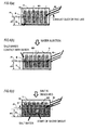
- the height position H of the installation position P1 from the lower face of the battery pack 5 is set to a predetermined water-submerged height, for example, as shown in FIGS. 6(a) to 6(c) , a height corresponding to the amount of water submergence in which the heat generation of the battery can be suppressed, for example, the position in which the half-height sh1 or more of each battery cell 801 is submerged.
- the installation position P1 (see FIG. 2 ) is disposed on the opposite side of the water injection port of the water injection route provided in the battery pack 5, that is, as shown in FIG. 2 , the upward opening 506 or the opening 631 of the exhaust side air duct 63 connected to the battery pack 5, with the drive battery 8 placed therebetween.
- the drive battery 8 is disposed between the opening 641 of the air duct 64 and the installation position P1 of the electrolyte substance M.
- the normally closed port 101 serving as the working hole of the floor 1 is opened, whereby the upward opening 506, for switch operation, connected thereto via the elastic cylindrical member 60 is opened, the handle 603 of the switch 60 just thereunder is rocked from the standby position p1 to the use position p2, and then the insertion plugs 601 and 601 connected to the handle 603 are pulled up and extracted, whereby the switch 60 is removed; as a result, the drive battery 8 of the battery pack 5 is disconnected from the high-voltage cables 11 extending from the electric power control apparatus 3 on the side of the electric rotating machine 1.
- tap water is injected through the upward opening 506.
- tap water is injected through the exhaust side air duct 64, whereby the electric energy of the drive battery 8 is discharged and deactivated, and electric shock, firing, etc. are prevented.
- the surface of the water in the battery pack 5 rises continuously upward from the half-height sh1 of the battery pack 5, whereby it can be judged that the installation position P1 of the electrolyte substance M is submerged and that the dissolution of the electrolyte substance M starts.
- an electrolyte aqueous solution increases gradually and the terminal electrodes t of the battery cells are submerged, whereby the discharge of the drive battery 8 is promoted safely, the electric energy stored in the drive battery 8 is discharged and deactivated in a relatively short time; as a result, electric shock, firing, etc. can be prevented, and the movement and conveyance of the disabled vehicle using a wrecker truck or the like can be carried out safely hereafter.
- the electrolyte substance M starts to be dissolved in the water; in other words, setting has been done so that, after a certain level of battery cooling performance or higher has been obtained securely, the electrolyte substance M is dissolved in water and becomes the electrolyte aqueous solution, whereby at the time when the electrolyte aqueous solution makes contact with the terminal electrodes t on the upper side of the drive battery 8 and the discharge starts, the cooling performance for the battery has been securely obtained sufficiently; as a result, a situation in which the battery generates heat excessively can be prevented securely and firing can be prevented.
- the installation position P1 is disposed on the opposite side of the water injection port of the water injection route provided in the battery pack 5, that is, the upward opening 506 or the opening 631 of the exhaust side air duct 63 connected to the battery pack 5, with the drive battery 8 placed therebetween; in other words, the drive battery 8 is disposed between the opening 631 of the air duct 63 and the installation position P1 of the electrolyte substance M.
- the installation position P1 is securely obtained on the opposite side of the upward opening 506 serving as the water injection port or the opening 641, with the battery placed therebetween, it is possible to exclude the possibility that the electrolyte substance is dissolved by water splashes immediately after the start of the water injection and that the electrolyte aqueous solution makes contact with the terminal electrodes of the drive battery 8 before a sufficient amount of water accumulates inside the battery pack. As a result, it is possible to reduce the occurrence of a situation in which the electrolyte aqueous solution makes contact with the terminal electrodes t immediately after the water injection and heat is generated.
- the height position H of the installation position P1 of the electrolyte substance M from the lower face of the battery pack 5 is set at the position slightly above the height corresponding to the level at which the drive battery 8 is submerged up to the half-height sh1 thereof; however, instead of this setting, as a battery energy discharge device according to a second embodiment, for example, as shown in FIG. 8(a) , the electrolyte substance M may be set so as to be installed above the terminal electrodes t of each battery cell 801 by a predetermined amount d1.
- the water dissolves the electrolyte substance and then the electrolyte aqueous solution makes contact with the terminal electrodes; hence, it is possible to securely prevent a situation in which the electrolyte aqueous solution makes direct contact with the terminal electrodes, heat is generated immediately, and firing occurs; as a result, safety can be enhanced further.
- the electrolyte substance M is installed at the installation position P1 using the container 70; however, as a modification example, a configuration may also be used in which the electrolyte substance M is wrapped with a water soluble wafer and held in the container 70, and when the surface of water reaches the installation position P1, the wafer is dissolved and the electrolyte substance M drops. This case is advantageous in that the electrolyte aqueous solution can be formed quickly.
- a battery energy discharge device As a battery energy discharge device according to a third embodiment, it may be possible, as shown in FIG. 8(b) , that a sheet 90 containing the electrolyte substance M is directly bonded to the inner wall wu using an adhesive 901, and when the surface of water reaches the installation position P1, the water dissolves the electrolyte substance M to form the electrolyte aqueous solution. Furthermore, in a battery energy discharge device according to a fourth embodiment, it may also be possible, as shown in FIG.
- the position located on the inner wall wu of the battery pack 5 and splashed with water only when water is supplied vigorously at the time of the water injection is set as the installation position P1 and that the electrolyte substance is disposed at the position; in this case, the degree of dissolution of the electrolyte substance can be adjusted by adjusting the amount of water to be injected.
- the installation position P1 of the electrolyte substance M is provided inside the battery pack 5; however, alternatively, as the battery energy discharge device according to a fifth embodiment, it may also be possible, as shown in FIG. 9 , that the container 70 preliminarily containing the electrolyte substance M is provided in the water filling route connected to the battery pack 5, for example, the exhaust side air duct 63, that is utilized securely and relatively easily in an emergency.
- the electrolyte substance M is dissolved in water when the water is injected into the exhaust side air duct 63, and the dissolved solution to be injected and having been converted into the electrolyte aqueous solution is supplied to the battery pack 5, whereby this embodiment is advantageous in the case that the electric energy stored in the drive battery 8 is required to be discharged in a relatively short time.
Landscapes
- Engineering & Computer Science (AREA)
- Chemical & Material Sciences (AREA)
- Chemical Kinetics & Catalysis (AREA)
- Electrochemistry (AREA)
- General Chemical & Material Sciences (AREA)
- Mechanical Engineering (AREA)
- Transportation (AREA)
- Power Engineering (AREA)
- Sustainable Energy (AREA)
- Sustainable Development (AREA)
- Life Sciences & Earth Sciences (AREA)
- Manufacturing & Machinery (AREA)
- Aviation & Aerospace Engineering (AREA)
- Combustion & Propulsion (AREA)
- Battery Mounting, Suspending (AREA)
- Electric Propulsion And Braking For Vehicles (AREA)
- Hybrid Electric Vehicles (AREA)
- Secondary Cells (AREA)
Applications Claiming Priority (2)
| Application Number | Priority Date | Filing Date | Title |
|---|---|---|---|
| JP2012111649A JP5953925B2 (ja) | 2012-05-15 | 2012-05-15 | 電池のエネルギ放出装置 |
| PCT/JP2013/063184 WO2013172271A1 (fr) | 2012-05-15 | 2013-05-10 | Dispositif de décharge d'énergie de batterie |
Publications (2)
| Publication Number | Publication Date |
|---|---|
| EP2851973A1 true EP2851973A1 (fr) | 2015-03-25 |
| EP2851973A4 EP2851973A4 (fr) | 2016-05-11 |
Family
ID=49583677
Family Applications (1)
| Application Number | Title | Priority Date | Filing Date |
|---|---|---|---|
| EP13791664.9A Withdrawn EP2851973A4 (fr) | 2012-05-15 | 2013-05-10 | Dispositif de décharge d'énergie de batterie |
Country Status (3)
| Country | Link |
|---|---|
| EP (1) | EP2851973A4 (fr) |
| JP (1) | JP5953925B2 (fr) |
| WO (1) | WO2013172271A1 (fr) |
Cited By (9)
| Publication number | Priority date | Publication date | Assignee | Title |
|---|---|---|---|---|
| CN104916880A (zh) * | 2015-06-18 | 2015-09-16 | 安徽江淮松芝空调有限公司 | 电动汽车电池水冷装置 |
| CN107408742A (zh) * | 2015-03-19 | 2017-11-28 | 株式会社自动网络技术研究所 | 蓄电组 |
| CN107921876A (zh) * | 2016-03-03 | 2018-04-17 | 株式会社Lg化学 | 用于车辆的电池系统 |
| CN110077464A (zh) * | 2019-05-17 | 2019-08-02 | 佟玉振 | 适用于纯电动新能源汽车的底盘 |
| US10766437B2 (en) * | 2017-12-14 | 2020-09-08 | Volkswagen Ag | Electric vehicle safety system and methods |
| US10938000B2 (en) | 2018-03-07 | 2021-03-02 | Tti (Macao Commercial Offshore) Limited | Arrangement for battery pack protection during fluid ingress |
| US12224419B2 (en) | 2019-07-08 | 2025-02-11 | Lg Energy Solution, Ltd. | Battery module having structure into which cooling water can be introduced when thermal runaway phenomenon occurs, and battery pack and energy storage device comprising same |
| US12407062B2 (en) | 2020-03-04 | 2025-09-02 | Lg Energy Solution, Ltd. | Battery module, battery rack comprising same battery module, and power storage device comprising same battery rack |
| US12469906B2 (en) | 2019-11-08 | 2025-11-11 | Lg Energy Solution, Ltd. | Battery module comprising a fire extinguisher, battery rack comprising same, and power storage device |
Families Citing this family (12)
| Publication number | Priority date | Publication date | Assignee | Title |
|---|---|---|---|---|
| US9312702B2 (en) * | 2011-12-08 | 2016-04-12 | GM Global Technology Operations LLC | System and methods for controlled depowering of automobile batteries |
| JP6229620B2 (ja) * | 2014-08-19 | 2017-11-15 | 株式会社豊田自動織機 | 充電設備 |
| KR101638143B1 (ko) * | 2014-12-09 | 2016-07-08 | 현대오트론 주식회사 | 배터리 방전 장치 및 방법 |
| KR101878042B1 (ko) * | 2016-07-12 | 2018-08-10 | 현대자동차주식회사 | 배터리팩 안전 장치 |
| JP2018012397A (ja) * | 2016-07-20 | 2018-01-25 | 本田技研工業株式会社 | 車載電源装置 |
| JP7006234B2 (ja) * | 2017-12-18 | 2022-01-24 | 株式会社Gsユアサ | 放電制御装置、蓄電システム及び蓄電素子の放電制御方法 |
| JP7061522B2 (ja) * | 2018-06-27 | 2022-04-28 | 本田技研工業株式会社 | バッテリパック及び電動車両 |
| JP7296967B2 (ja) * | 2018-08-06 | 2023-06-23 | 三洋電機株式会社 | 電源装置及びこれを備える車両 |
| JP7229633B2 (ja) * | 2018-09-28 | 2023-02-28 | ダイハツ工業株式会社 | 電池、水溶液収容体、電池輸送容器 |
| JP7551440B2 (ja) * | 2020-10-14 | 2024-09-17 | 株式会社Subaru | 車両の走行用電池の再利用防止方法 |
| CN114069097B (zh) * | 2021-11-15 | 2024-06-14 | 中国第一汽车股份有限公司 | 一种热失控处理系统和热失控处理方法 |
| CN115050982A (zh) * | 2022-03-10 | 2022-09-13 | 湖南金凯循环科技有限公司 | 一种电池放电处理装置 |
Family Cites Families (13)
| Publication number | Priority date | Publication date | Assignee | Title |
|---|---|---|---|---|
| JPS5979964A (ja) | 1982-10-30 | 1984-05-09 | Japan Storage Battery Co Ltd | 防爆形組電池 |
| JPH09107628A (ja) * | 1995-10-11 | 1997-04-22 | Sumitomo Wiring Syst Ltd | 電気自動車及びその電源装置 |
| JPH09284904A (ja) | 1996-04-05 | 1997-10-31 | Toyota Motor Corp | 車両の安全装置 |
| JP2001332237A (ja) * | 2000-05-19 | 2001-11-30 | Shikoku Electric Power Co Inc | 電池装置 |
| JP3893965B2 (ja) | 2001-12-13 | 2007-03-14 | トヨタ自動車株式会社 | 電気式自動車 |
| JP2005347162A (ja) * | 2004-06-04 | 2005-12-15 | Nec Tokin Tochigi Ltd | 廃棄電池の放電方法 |
| JP2008041507A (ja) * | 2006-08-08 | 2008-02-21 | Sanyo Electric Co Ltd | 浸水検知スイッチ及び該浸水検知スイッチを備える電池パック |
| JP5352325B2 (ja) * | 2009-04-09 | 2013-11-27 | トヨタ自動車株式会社 | 蓄電装置および、蓄電装置の放電方法 |
| JP2010277737A (ja) | 2009-05-27 | 2010-12-09 | Jfe Kankyo Corp | リチウム電池の処理方法 |
| JP2012033345A (ja) * | 2010-07-29 | 2012-02-16 | Sumitomo Metal Mining Co Ltd | 電池パック |
| DE102010034826A1 (de) * | 2010-08-19 | 2012-02-23 | Li-Tec Battery Gmbh | Elektrochemischer Energiespeicher mit einer Mehrzahl von elektrochemischen Zellen |
| US9312702B2 (en) * | 2011-12-08 | 2016-04-12 | GM Global Technology Operations LLC | System and methods for controlled depowering of automobile batteries |
| JP2013154809A (ja) * | 2012-01-31 | 2013-08-15 | Mitsubishi Motors Corp | 電動車 |
-
2012
- 2012-05-15 JP JP2012111649A patent/JP5953925B2/ja not_active Expired - Fee Related
-
2013
- 2013-05-10 EP EP13791664.9A patent/EP2851973A4/fr not_active Withdrawn
- 2013-05-10 WO PCT/JP2013/063184 patent/WO2013172271A1/fr not_active Ceased
Cited By (13)
| Publication number | Priority date | Publication date | Assignee | Title |
|---|---|---|---|---|
| CN107408742A (zh) * | 2015-03-19 | 2017-11-28 | 株式会社自动网络技术研究所 | 蓄电组 |
| CN104916880A (zh) * | 2015-06-18 | 2015-09-16 | 安徽江淮松芝空调有限公司 | 电动汽车电池水冷装置 |
| CN107921876A (zh) * | 2016-03-03 | 2018-04-17 | 株式会社Lg化学 | 用于车辆的电池系统 |
| EP3308994A4 (fr) * | 2016-03-03 | 2018-06-13 | LG Chem, Ltd. | Système de batterie de véhicule |
| CN107921876B (zh) * | 2016-03-03 | 2021-02-19 | 株式会社Lg化学 | 用于车辆的电池系统 |
| US10680298B2 (en) | 2016-03-03 | 2020-06-09 | Lg Chem, Ltd. | Battery system for vehicle |
| US10766437B2 (en) * | 2017-12-14 | 2020-09-08 | Volkswagen Ag | Electric vehicle safety system and methods |
| US11084432B2 (en) | 2017-12-14 | 2021-08-10 | Volkswagen Aktiengesellschaft | Electric vehicle safety system and methods |
| US10938000B2 (en) | 2018-03-07 | 2021-03-02 | Tti (Macao Commercial Offshore) Limited | Arrangement for battery pack protection during fluid ingress |
| CN110077464A (zh) * | 2019-05-17 | 2019-08-02 | 佟玉振 | 适用于纯电动新能源汽车的底盘 |
| US12224419B2 (en) | 2019-07-08 | 2025-02-11 | Lg Energy Solution, Ltd. | Battery module having structure into which cooling water can be introduced when thermal runaway phenomenon occurs, and battery pack and energy storage device comprising same |
| US12469906B2 (en) | 2019-11-08 | 2025-11-11 | Lg Energy Solution, Ltd. | Battery module comprising a fire extinguisher, battery rack comprising same, and power storage device |
| US12407062B2 (en) | 2020-03-04 | 2025-09-02 | Lg Energy Solution, Ltd. | Battery module, battery rack comprising same battery module, and power storage device comprising same battery rack |
Also Published As
| Publication number | Publication date |
|---|---|
| EP2851973A4 (fr) | 2016-05-11 |
| JP2013237355A (ja) | 2013-11-28 |
| JP5953925B2 (ja) | 2016-07-20 |
| WO2013172271A1 (fr) | 2013-11-21 |
Similar Documents
| Publication | Publication Date | Title |
|---|---|---|
| EP2851973A1 (fr) | Dispositif de décharge d'énergie de batterie | |
| US11978845B2 (en) | Vent shield for a battery module | |
| CN102448752B (zh) | 燃料电池系统及车辆 | |
| US9627721B2 (en) | Electricity storage device and vehicle | |
| US20180178641A1 (en) | Fuel cell mounting structure | |
| US9077019B2 (en) | Electricity storage device and vehicle | |
| CN103311477B (zh) | 铁道车辆用的电池箱和铁道车辆 | |
| US20140062418A1 (en) | Safety apparatus for battery module of electric vehicle | |
| CN102646796A (zh) | 蓄电池模块 | |
| US9487096B2 (en) | Charging device | |
| CN107406002B (zh) | 车载用蓄电装置 | |
| CN104507735A (zh) | 作业车辆 | |
| US10559795B1 (en) | Chassis brace for protecting traction battery | |
| US6355373B1 (en) | Battery | |
| CN109795301A (zh) | 电动汽车电池包、电动汽车及换电站 | |
| KR20160111234A (ko) | 전기자동차용 소형 이차 전지 매트릭스 제어장치 및 방법 | |
| CN116057758A (zh) | 电池组框架以及包括该电池组框架的电池架和储能系统 | |
| EP4552895A1 (fr) | Appareil et procédé de protection de bloc-batterie | |
| CN114763068A (zh) | 一种车用充电宝系统及充电方法 | |
| JP2012033299A (ja) | 蓄電装置 | |
| EP3686050B1 (fr) | Protection contre le gaz de batterie emis en cas de défaillance de la batterie | |
| KR20210066324A (ko) | 차량용 멀티 배터리 장치 및 이를 포함하는 차량 | |
| EP4250455A1 (fr) | Bâti de batterie et système de stockage d'énergie le comprenant | |
| US20240178483A1 (en) | Power Storage Device and Vehicle | |
| US11791490B2 (en) | Housing |
Legal Events
| Date | Code | Title | Description |
|---|---|---|---|
| PUAI | Public reference made under article 153(3) epc to a published international application that has entered the european phase |
Free format text: ORIGINAL CODE: 0009012 |
|
| 17P | Request for examination filed |
Effective date: 20141212 |
|
| AK | Designated contracting states |
Kind code of ref document: A1 Designated state(s): AL AT BE BG CH CY CZ DE DK EE ES FI FR GB GR HR HU IE IS IT LI LT LU LV MC MK MT NL NO PL PT RO RS SE SI SK SM TR |
|
| AX | Request for extension of the european patent |
Extension state: BA ME |
|
| DAX | Request for extension of the european patent (deleted) | ||
| RIC1 | Information provided on ipc code assigned before grant |
Ipc: B60L 11/18 20060101ALI20151215BHEP Ipc: B60K 1/00 20060101ALN20151215BHEP Ipc: H01M 10/6556 20140101ALI20151215BHEP Ipc: H01M 2/10 20060101AFI20151215BHEP Ipc: B60K 6/28 20071001ALI20151215BHEP Ipc: B60L 3/04 20060101ALI20151215BHEP Ipc: H01M 2/36 20060101ALI20151215BHEP Ipc: H01M 10/6567 20140101ALI20151215BHEP Ipc: B60L 3/00 20060101ALI20151215BHEP Ipc: B60K 1/04 20060101ALN20151215BHEP Ipc: H01M 10/625 20140101ALI20151215BHEP Ipc: H01M 10/44 20060101ALI20151215BHEP Ipc: H01M 10/613 20140101ALI20151215BHEP |
|
| RA4 | Supplementary search report drawn up and despatched (corrected) |
Effective date: 20160412 |
|
| RIC1 | Information provided on ipc code assigned before grant |
Ipc: B60K 6/28 20071001ALI20160406BHEP Ipc: H01M 10/6556 20140101ALI20160406BHEP Ipc: B60K 1/04 20060101ALN20160406BHEP Ipc: H01M 10/613 20140101ALI20160406BHEP Ipc: H01M 10/44 20060101ALI20160406BHEP Ipc: B60L 3/00 20060101ALI20160406BHEP Ipc: H01M 10/6567 20140101ALI20160406BHEP Ipc: H01M 10/625 20140101ALI20160406BHEP Ipc: H01M 2/10 20060101AFI20160406BHEP Ipc: B60L 3/04 20060101ALI20160406BHEP Ipc: B60L 11/18 20060101ALI20160406BHEP Ipc: H01M 2/36 20060101ALI20160406BHEP Ipc: B60K 1/00 20060101ALN20160406BHEP |
|
| 17Q | First examination report despatched |
Effective date: 20180319 |
|
| RIC1 | Information provided on ipc code assigned before grant |
Ipc: H01M 2/10 20060101AFI20160406BHEP Ipc: H01M 10/625 20140101ALI20160406BHEP Ipc: B60K 1/00 20060101ALN20160406BHEP Ipc: H01M 2/36 20060101ALI20160406BHEP Ipc: B60L 3/00 20190101ALI20160406BHEP Ipc: H01M 10/6556 20140101ALI20160406BHEP Ipc: B60L 11/18 20060101ALI20160406BHEP Ipc: H01M 10/44 20060101ALI20160406BHEP Ipc: H01M 10/6567 20140101ALI20160406BHEP Ipc: H01M 10/613 20140101ALI20160406BHEP Ipc: B60K 1/04 20190101ALN20160406BHEP Ipc: B60K 6/28 20071001ALI20160406BHEP Ipc: B60L 3/04 20060101ALI20160406BHEP |
|
| RIC1 | Information provided on ipc code assigned before grant |
Ipc: H01M 10/6556 20140101ALI20190401BHEP Ipc: B60L 50/64 20190101ALI20190401BHEP Ipc: B60L 3/00 20190101ALI20190401BHEP Ipc: H01M 10/44 20060101ALI20190401BHEP Ipc: B60L 58/26 20190101ALI20190401BHEP Ipc: H01M 2/10 20060101AFI20190401BHEP Ipc: H01M 10/625 20140101ALI20190401BHEP Ipc: B60L 58/21 20190101ALI20190401BHEP Ipc: H01M 10/6567 20140101ALI20190401BHEP Ipc: B60K 1/04 20190101ALN20190401BHEP Ipc: H01M 10/613 20140101ALI20190401BHEP Ipc: B60K 1/00 20060101ALN20190401BHEP Ipc: H01M 2/36 20060101ALI20190401BHEP Ipc: B60L 3/04 20060101ALI20190401BHEP Ipc: B60K 6/28 20071001ALI20190401BHEP Ipc: B60L 50/60 20190101ALI20190401BHEP |
|
| GRAP | Despatch of communication of intention to grant a patent |
Free format text: ORIGINAL CODE: EPIDOSNIGR1 |
|
| INTG | Intention to grant announced |
Effective date: 20190522 |
|
| RAP1 | Party data changed (applicant data changed or rights of an application transferred) |
Owner name: MITSUBISHI JIDOSHA KOGYO KABUSHIKI KAISHA |
|
| STAA | Information on the status of an ep patent application or granted ep patent |
Free format text: STATUS: THE APPLICATION IS DEEMED TO BE WITHDRAWN |
|
| 18D | Application deemed to be withdrawn |
Effective date: 20191002 |