EP2852032A1 - Rotor pour une machine dynamoélectrique - Google Patents
Rotor pour une machine dynamoélectrique Download PDFInfo
- Publication number
- EP2852032A1 EP2852032A1 EP13185766.6A EP13185766A EP2852032A1 EP 2852032 A1 EP2852032 A1 EP 2852032A1 EP 13185766 A EP13185766 A EP 13185766A EP 2852032 A1 EP2852032 A1 EP 2852032A1
- Authority
- EP
- European Patent Office
- Prior art keywords
- conductors
- rotor
- conductor
- longitudinal groove
- distance
- Prior art date
- Legal status (The legal status is an assumption and is not a legal conclusion. Google has not performed a legal analysis and makes no representation as to the accuracy of the status listed.)
- Withdrawn
Links
Images

Classifications
-
- H—ELECTRICITY
- H02—GENERATION; CONVERSION OR DISTRIBUTION OF ELECTRIC POWER
- H02K—DYNAMO-ELECTRIC MACHINES
- H02K3/00—Details of windings
- H02K3/04—Windings characterised by the conductor shape, form or construction, e.g. with bar conductors
- H02K3/24—Windings characterised by the conductor shape, form or construction, e.g. with bar conductors with channels or ducts for cooling medium between the conductors
-
- H—ELECTRICITY
- H02—GENERATION; CONVERSION OR DISTRIBUTION OF ELECTRIC POWER
- H02K—DYNAMO-ELECTRIC MACHINES
- H02K3/00—Details of windings
- H02K3/32—Windings characterised by the shape, form or construction of the insulation
- H02K3/34—Windings characterised by the shape, form or construction of the insulation between conductors or between conductor and core, e.g. slot insulation
Definitions
- the invention relates to a rotor for a dynamoelectric machine, in whose cylindrical rotor body a plurality of longitudinal grooves extends, in which a field winding is arranged, wherein each longitudinal groove a plurality of conductors are arranged one above the other in different conductor planes.
- the rotor according to the invention can be used in particular for large two-pole synchronous machines, where the excitation winding formed as coils are inserted into milled longitudinal grooves of the rotor body.
- the coils are usually made of solid copper conductors.
- the conductors must be insulated against each other and against the grooves. At the same time a good heat dissipation for the conductors of the excitation winding must be guaranteed.
- the cooling of the exciter winding is usually achieved with cooling air 8.
- the cooling air 8 flows through axial channels into the rotor and through branching off radial channels, which continue through the longitudinal grooves 12, to the conductors 4. These have holes, so that through the holes in superimposed conductors, the radial Continue channels. Also in the insulating inserts 5 and in the wedges 2, which fasten the conductors 4 in the longitudinal grooves 12, corresponding holes are provided. The preparation of these radial cooling channels through the conductor 4 is very laborious.
- a rotor for a dynamoelectric machine with the features of claim 1, wherein in the cylindrical rotor body a plurality of longitudinal grooves extends, in which a field winding is arranged, wherein each longitudinal groove a plurality of conductors are arranged one above the other in different conductor planes.
- the invention provides that the excitation winding consists of insulated conductors, wherein in each longitudinal groove per conductor level at least two conductors are arranged parallel to each other and at a distance to each other, so that a plurality of superposed conductor pairs form at least one radially extending cooling channel.
- Each turn of a coil of the field winding thus consists of approximately two parallel conductors or wires.
- the conductor insulation of the insulated conductors may be a lacquer layer or a tissue sheath.
- the distance between parallel conductors in a longitudinal groove is produced by insulating spacer inserts, wherein the spacer inserts are spaced apart in the axial direction, so that the distances between the spacer inserts form radially extending cooling channels.
- the distance deposits can be formed approximately from an insulating material.
- the spacer inserts may be, for example, substantially rectangular plates made of an insulating material. Which insulating material is used, depends on the desired or required properties of the rotor, such as whether an impregnation of the spacer inserts should take place and optionally which impregnating agent is used.
- the common length of the spacer inserts should be as small as possible (ie in the axial direction be as large a distance as possible between the individual distance deposits a layer), so that sufficiently large cooling channels can be formed and sufficient cooling air can flow through the radial air channels, which are seen in the axial direction between the distance deposits.
- the mechanical stability of the excitation winding must be ensured, with long axial distances between the distance deposits have a negative impact on the stability.
- the common length of the distance inserts should be as large as possible (ie in the axial direction the smallest possible distance between the individual distance deposits of a layer).
- axial channels for cooling air will be provided in the rotor body, of which each branch off a plurality of radial channels, which continue through the longitudinal grooves (between the distance deposits).
- the cooling effect with the rotor according to the invention is comparable to the cooling effect with direct cooling of bare conductors.
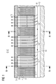
- Fig. 1 shows a longitudinal section through a rotor according to the prior art.
- the exciter winding of bare conductors 4 without insulation wherein a conductor 4 occupies the entire width of the longitudinal groove.
- insulation inserts 5 In the radial direction, the insulation between the conductors 4 with inserts of insulating material, so-called insulation inserts 5, is produced.
- the main insulation 6 against the Nuteisen form groove boxes made of insulating material.
- the cooling of the exciter winding is achieved with cooling air 8.
- the cooling air 8 flows through axial channels 13 into the rotor body 1 and through branching off radial channels 14, which continue through the longitudinal grooves 12, to the conductors 4th
- the wedge 2 for closing the longitudinal groove 12 has per radial channel 14 more - here four - nozzles 15 for discharging the cooling air.
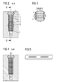
- Fig. 2 is a cross section through a longitudinal groove 12 of the rotor Fig. 1 represented along AA, that is, a section through a region of the superposed conductor 4, which does not include holes and thus no radial channel 14.
- Fig. 4 the cross-section is shown by a longitudinal groove with a radial channel for cooling, namely as a section along BB Fig. 1 , Here, therefore, the congruent superimposed holes in the conductors 4 can be seen.
- Fig. 6 shows a longitudinal section through a rotor according to the invention, namely centrally through a longitudinal groove 12. There are per longitudinal groove 12 each two parallel insulated conductors 9 without holes spaced from one another next to each other. In Fig. 6 Therefore, one sees only one of the two stacks of ladders 9 and the spacing inserts 10 arranged between the stacks.
- the mutual distance of the distance inserts 10 is in the axial direction (from left to right in Fig. 6 ) greater than their width.
- the width of all radial channels 14 together is greater than the width of all spacer 10th
- the conductor insulation 11 is designed here as a tissue sheath.
- the wedge 2 for closing the longitudinal groove 12, the insulation 3 under the wedge 2, the main insulation 5 and the bottom insulation 7 are as in FIG Fig. 1 executed.
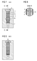
- Fig. 7 to 9 is the mutual arrangement of the conductor pairs, once with and once without spacer insert 10, recognizable.
- the mutual distance between the two conductors 9 of a conductor level corresponds to the width of the holes in conductor 4 Fig. 5 according to the prior art.
- the cooling air 8 flows through the axial channels 13 under the longitudinal grooves 12, through the holes in the groove bottom (whose length in the axial direction to the respective distance between the Spacing inserts 10), through corresponding holes in the bottom insulation 7, through the space between the parallel conductors 9, through the corresponding holes in the insulation 3 under the wedge 2 and through the nozzles 15 in the wedge 2 into the air gap between the rotor and the stator.
Landscapes
- Engineering & Computer Science (AREA)
- Power Engineering (AREA)
- Motor Or Generator Cooling System (AREA)
- Windings For Motors And Generators (AREA)
Priority Applications (1)
| Application Number | Priority Date | Filing Date | Title |
|---|---|---|---|
| EP13185766.6A EP2852032A1 (fr) | 2013-09-24 | 2013-09-24 | Rotor pour une machine dynamoélectrique |
Applications Claiming Priority (1)
| Application Number | Priority Date | Filing Date | Title |
|---|---|---|---|
| EP13185766.6A EP2852032A1 (fr) | 2013-09-24 | 2013-09-24 | Rotor pour une machine dynamoélectrique |
Publications (1)
| Publication Number | Publication Date |
|---|---|
| EP2852032A1 true EP2852032A1 (fr) | 2015-03-25 |
Family
ID=49303729
Family Applications (1)
| Application Number | Title | Priority Date | Filing Date |
|---|---|---|---|
| EP13185766.6A Withdrawn EP2852032A1 (fr) | 2013-09-24 | 2013-09-24 | Rotor pour une machine dynamoélectrique |
Country Status (1)
| Country | Link |
|---|---|
| EP (1) | EP2852032A1 (fr) |
Cited By (2)
| Publication number | Priority date | Publication date | Assignee | Title |
|---|---|---|---|---|
| CN111740524A (zh) * | 2020-07-10 | 2020-10-02 | 陕西航空电气有限责任公司 | 一种发电机转子绕组散热结构及其装配方法 |
| EP4106152A1 (fr) * | 2021-06-17 | 2022-12-21 | General Electric Company | Masse magnétique pour rotor, rotor associé et machine tournante électrique |
Citations (4)
| Publication number | Priority date | Publication date | Assignee | Title |
|---|---|---|---|---|
| EP0595609A1 (fr) * | 1992-10-29 | 1994-05-04 | General Electric Company | Enroulement rotorique |
| US5722153A (en) * | 1991-08-28 | 1998-03-03 | General Electric Company | Method for fabricating a split-loop armature coil for a motor |
| DE19749316A1 (de) * | 1997-11-07 | 1999-05-12 | Abb Patent Gmbh | Gasgekühlter Turbogenerator |
| WO2013112067A1 (fr) * | 2012-01-26 | 2013-08-01 | General Electric Company | Machine dynamo-électrique dotée d'une ventilation de rotor améliorée |
-
2013
- 2013-09-24 EP EP13185766.6A patent/EP2852032A1/fr not_active Withdrawn
Patent Citations (4)
| Publication number | Priority date | Publication date | Assignee | Title |
|---|---|---|---|---|
| US5722153A (en) * | 1991-08-28 | 1998-03-03 | General Electric Company | Method for fabricating a split-loop armature coil for a motor |
| EP0595609A1 (fr) * | 1992-10-29 | 1994-05-04 | General Electric Company | Enroulement rotorique |
| DE19749316A1 (de) * | 1997-11-07 | 1999-05-12 | Abb Patent Gmbh | Gasgekühlter Turbogenerator |
| WO2013112067A1 (fr) * | 2012-01-26 | 2013-08-01 | General Electric Company | Machine dynamo-électrique dotée d'une ventilation de rotor améliorée |
Cited By (3)
| Publication number | Priority date | Publication date | Assignee | Title |
|---|---|---|---|---|
| CN111740524A (zh) * | 2020-07-10 | 2020-10-02 | 陕西航空电气有限责任公司 | 一种发电机转子绕组散热结构及其装配方法 |
| CN111740524B (zh) * | 2020-07-10 | 2022-09-06 | 陕西航空电气有限责任公司 | 一种发电机转子绕组散热结构及其装配方法 |
| EP4106152A1 (fr) * | 2021-06-17 | 2022-12-21 | General Electric Company | Masse magnétique pour rotor, rotor associé et machine tournante électrique |
Similar Documents
| Publication | Publication Date | Title |
|---|---|---|
| DE2930396C2 (fr) | ||
| EP3459160B1 (fr) | Barre omnibus de generateur refroidie a l'eau comprenant un espace de separation de canal de refroidissement | |
| DE102018129229B4 (de) | Elektrische Maschine mit mehreren als Hohlleiter ausgebildeten starren Wicklungsstücken - hydraulisches Anschlusskonzept I | |
| EP2933901A1 (fr) | Stator d'une machine électrique et sa fabrication | |
| DE2434347A1 (de) | Luftspaltwicklung einer elektrischen maschine | |
| DE112014004639T5 (de) | Drehende elektrische Maschine und Herstellungsverfahren für diese | |
| DE102019008668A1 (de) | Statorvorrichtung für eine elektrische Maschine mit einer separaten Kühleinrichtung, sowie elektrische Maschine | |
| EP3142228A1 (fr) | Stator de machine electrique et machine electrique et procede de fabrication | |
| DE102011081280B4 (de) | Röntgenanordnung mit Antrieb für Drehanode mit Stator mit Jochwicklung | |
| DE102015103027A1 (de) | Einteilige Nutauskleidung für mehrschichtige elektrische Maschinen | |
| EP1258071B1 (fr) | Machine a rotation haute tension et procede de refroidissement des conducteurs de cette machine | |
| DE102005002364B4 (de) | Drehstrommaschine | |
| WO2013045240A2 (fr) | Moteur électrique muni d'un stator à intervalle variable entre rainures | |
| DE102018206003A1 (de) | Vorrichtung und Verfahren zur Ausrichtung einer Hairpinwicklung | |
| DE102018206512A1 (de) | Elektrische Maschine und hybridelektrisches Luftfahrzeug | |
| DE102018125829A1 (de) | Stator für eine elektrische Maschine | |
| DE202010016269U1 (de) | Statorstab | |
| DE19653060A1 (de) | Gasgekühlte elektrische Maschine | |
| EP2852032A1 (fr) | Rotor pour une machine dynamoélectrique | |
| DE102013103441A1 (de) | Modulare halterung fuer elektrische leiter | |
| EP2905875A1 (fr) | Élément principal d'une machine électrique | |
| DE102015116810A1 (de) | Elektromotor-Bauteil und Elektromotor mit wenigstens einer Wicklung | |
| DE102018125834A1 (de) | Stator für eine elektrische Maschine und Verfahren zum Herstellen eines derartigen Stators | |
| DE2150163C3 (de) | Anordnung zur Versteifung von Wickelköpfen in elektrischen Maschinen | |
| DE112015004183T5 (de) | Stator mit einer guten Keilhalterung bei optimiertem magnetischen Kreis und Verfahren zur elektrischen Isolation eines derartigen Stators |
Legal Events
| Date | Code | Title | Description |
|---|---|---|---|
| PUAI | Public reference made under article 153(3) epc to a published international application that has entered the european phase |
Free format text: ORIGINAL CODE: 0009012 |
|
| 17P | Request for examination filed |
Effective date: 20130924 |
|
| AK | Designated contracting states |
Kind code of ref document: A1 Designated state(s): AL AT BE BG CH CY CZ DE DK EE ES FI FR GB GR HR HU IE IS IT LI LT LU LV MC MK MT NL NO PL PT RO RS SE SI SK SM TR |
|
| AX | Request for extension of the european patent |
Extension state: BA ME |
|
| STAA | Information on the status of an ep patent application or granted ep patent |
Free format text: STATUS: THE APPLICATION IS DEEMED TO BE WITHDRAWN |
|
| 18D | Application deemed to be withdrawn |
Effective date: 20150926 |